EP3308361B1 - Method for generating a virtual image of vehicle surroundings - Google Patents
Method for generating a virtual image of vehicle surroundings Download PDFInfo
- Publication number
- EP3308361B1 EP3308361B1 EP16742156.9A EP16742156A EP3308361B1 EP 3308361 B1 EP3308361 B1 EP 3308361B1 EP 16742156 A EP16742156 A EP 16742156A EP 3308361 B1 EP3308361 B1 EP 3308361B1
- Authority
- EP
- European Patent Office
- Prior art keywords
- vehicle
- projection points
- projection
- environment
- distance
- Prior art date
- Legal status (The legal status is an assumption and is not a legal conclusion. Google has not performed a legal analysis and makes no representation as to the accuracy of the status listed.)
- Active
Links
- 238000000034 method Methods 0.000 title claims description 31
- 238000004364 calculation method Methods 0.000 claims description 3
- 230000006870 function Effects 0.000 description 11
- 230000007613 environmental effect Effects 0.000 description 9
- 238000005070 sampling Methods 0.000 description 6
- 235000004522 Pentaglottis sempervirens Nutrition 0.000 description 3
- 238000012545 processing Methods 0.000 description 3
- 238000004422 calculation algorithm Methods 0.000 description 2
- 230000001419 dependent effect Effects 0.000 description 2
- 238000013461 design Methods 0.000 description 2
- 238000013519 translation Methods 0.000 description 2
- 238000004590 computer program Methods 0.000 description 1
- 230000003247 decreasing effect Effects 0.000 description 1
- 238000001514 detection method Methods 0.000 description 1
- 230000001627 detrimental effect Effects 0.000 description 1
- 238000003384 imaging method Methods 0.000 description 1
- 238000012806 monitoring device Methods 0.000 description 1
- 230000003068 static effect Effects 0.000 description 1
Images

Classifications
-
- H—ELECTRICITY
- H04—ELECTRIC COMMUNICATION TECHNIQUE
- H04N—PICTORIAL COMMUNICATION, e.g. TELEVISION
- H04N13/00—Stereoscopic video systems; Multi-view video systems; Details thereof
- H04N13/10—Processing, recording or transmission of stereoscopic or multi-view image signals
- H04N13/106—Processing image signals
- H04N13/111—Transformation of image signals corresponding to virtual viewpoints, e.g. spatial image interpolation
-
- G—PHYSICS
- G06—COMPUTING; CALCULATING OR COUNTING
- G06T—IMAGE DATA PROCESSING OR GENERATION, IN GENERAL
- G06T15/00—3D [Three Dimensional] image rendering
- G06T15/10—Geometric effects
-
- G—PHYSICS
- G06—COMPUTING; CALCULATING OR COUNTING
- G06T—IMAGE DATA PROCESSING OR GENERATION, IN GENERAL
- G06T15/00—3D [Three Dimensional] image rendering
- G06T15/10—Geometric effects
- G06T15/20—Perspective computation
- G06T15/205—Image-based rendering
-
- G—PHYSICS
- G09—EDUCATION; CRYPTOGRAPHY; DISPLAY; ADVERTISING; SEALS
- G09B—EDUCATIONAL OR DEMONSTRATION APPLIANCES; APPLIANCES FOR TEACHING, OR COMMUNICATING WITH, THE BLIND, DEAF OR MUTE; MODELS; PLANETARIA; GLOBES; MAPS; DIAGRAMS
- G09B9/00—Simulators for teaching or training purposes
- G09B9/02—Simulators for teaching or training purposes for teaching control of vehicles or other craft
- G09B9/04—Simulators for teaching or training purposes for teaching control of vehicles or other craft for teaching control of land vehicles
- G09B9/05—Simulators for teaching or training purposes for teaching control of vehicles or other craft for teaching control of land vehicles the view from a vehicle being simulated
-
- H—ELECTRICITY
- H04—ELECTRIC COMMUNICATION TECHNIQUE
- H04N—PICTORIAL COMMUNICATION, e.g. TELEVISION
- H04N7/00—Television systems
- H04N7/18—Closed-circuit television [CCTV] systems, i.e. systems in which the video signal is not broadcast
- H04N7/181—Closed-circuit television [CCTV] systems, i.e. systems in which the video signal is not broadcast for receiving images from a plurality of remote sources
-
- B—PERFORMING OPERATIONS; TRANSPORTING
- B60—VEHICLES IN GENERAL
- B60R—VEHICLES, VEHICLE FITTINGS, OR VEHICLE PARTS, NOT OTHERWISE PROVIDED FOR
- B60R2300/00—Details of viewing arrangements using cameras and displays, specially adapted for use in a vehicle
- B60R2300/10—Details of viewing arrangements using cameras and displays, specially adapted for use in a vehicle characterised by the type of camera system used
- B60R2300/105—Details of viewing arrangements using cameras and displays, specially adapted for use in a vehicle characterised by the type of camera system used using multiple cameras
-
- B—PERFORMING OPERATIONS; TRANSPORTING
- B60—VEHICLES IN GENERAL
- B60R—VEHICLES, VEHICLE FITTINGS, OR VEHICLE PARTS, NOT OTHERWISE PROVIDED FOR
- B60R2300/00—Details of viewing arrangements using cameras and displays, specially adapted for use in a vehicle
- B60R2300/30—Details of viewing arrangements using cameras and displays, specially adapted for use in a vehicle characterised by the type of image processing
- B60R2300/303—Details of viewing arrangements using cameras and displays, specially adapted for use in a vehicle characterised by the type of image processing using joined images, e.g. multiple camera images
-
- B—PERFORMING OPERATIONS; TRANSPORTING
- B60—VEHICLES IN GENERAL
- B60R—VEHICLES, VEHICLE FITTINGS, OR VEHICLE PARTS, NOT OTHERWISE PROVIDED FOR
- B60R2300/00—Details of viewing arrangements using cameras and displays, specially adapted for use in a vehicle
- B60R2300/60—Details of viewing arrangements using cameras and displays, specially adapted for use in a vehicle characterised by monitoring and displaying vehicle exterior scenes from a transformed perspective
- B60R2300/607—Details of viewing arrangements using cameras and displays, specially adapted for use in a vehicle characterised by monitoring and displaying vehicle exterior scenes from a transformed perspective from a bird's eye viewpoint
-
- G—PHYSICS
- G06—COMPUTING; CALCULATING OR COUNTING
- G06T—IMAGE DATA PROCESSING OR GENERATION, IN GENERAL
- G06T2207/00—Indexing scheme for image analysis or image enhancement
- G06T2207/30—Subject of image; Context of image processing
- G06T2207/30248—Vehicle exterior or interior
- G06T2207/30252—Vehicle exterior; Vicinity of vehicle
-
- G—PHYSICS
- G06—COMPUTING; CALCULATING OR COUNTING
- G06T—IMAGE DATA PROCESSING OR GENERATION, IN GENERAL
- G06T2215/00—Indexing scheme for image rendering
- G06T2215/12—Shadow map, environment map
Definitions
- the invention relates to a method for generating a virtual image of a vehicle environment using a three-dimensional environment model, in particular for use in a vehicle which has a camera surround view system.
- Vehicles are increasingly being equipped with driver assistance systems that support the driver in carrying out driving maneuvers.
- Some of these driver assistance systems contain camera surround view systems that allow the vehicle's surroundings to be shown to the driver of the vehicle.
- Such camera surround view systems comprise one or more vehicle cameras that provide real images of the vehicle's surroundings that are combined by a data processing unit of the camera surround view system to form an environmental image of the vehicle's surroundings. The image of the vehicle's surroundings is then shown to the driver on a display unit.
- the real images of the vehicle's surroundings obtained by the cameras of the camera surround view system must first be projected onto projection points of a virtual environmental model of the vehicle's surroundings.
- the image displayed on the display unit can then be calculated from the perspective of a virtual camera onto the virtual image of the vehicle's surroundings generated in this way.
- the position of the virtual camera for calculating the displayed image can be varied so that the driver can be shown a different representation of the vehicle's surroundings as required or depending on the driving situation.
- the choice of the three-dimensional environment model for the projection of the real Images as well as the generation of the virtual image is crucial for the quality of the displayed image.
- the disclosure document EN 10 2012 203 523 A1 discloses a generic method for image processing of image data of respective images captured by multiple cameras arranged on a vehicle, in which a geometry of a three-dimensional environment model is provided which has a flat floor area that lies in a standing plane of the vehicle and which has a surface that has a floor surface of the flat floor area and that delimits an environmental space that also includes the vehicle.
- the image data of the respective images from the various cameras are projected onto the surface of this three-dimensional environment model as environment model image data.
- the image data of an image to be signaled are then determined from the perspective of a virtual camera on the surface of the three-dimensional environment model, which takes place in the sense of a mirror image representation when a predetermined condition is met.
- US 2004/0260469 A1 a driving assistance system comprising an imaging means for capturing an environmental image of a vehicle on a road surface and an image translation means for performing image translation using a three-dimensional projection model which is convex to a road surface side and whose height depends on the Road surface is not changed within a predetermined range from an upper end portion of the vehicle in the traveling direction.
- the three-dimensional projection model is configured by a cylindrical surface model convex to the road surface side and a spherical surface model connected to an end portion of the cylindrical surface model.
- US 2013/0155241 A1 an environment monitoring device for a work vehicle comprising a first image unit, an image generation unit and a display unit.
- the first image unit is attached to the work vehicle and designed to capture an image of a first area in an environment of the work vehicle.
- the image generation unit is configured to create a bird's eye view image of the environment of the work vehicle by projecting the captured image onto a predetermined virtual projection plane.
- the virtual projection plane includes a shape whose height from a ground surface increases with decreasing distance from the work vehicle.
- the display unit is configured and arranged to display the bird's eye view image.
- Conventional camera-based driver assistance systems thus project texture information from the camera system onto a static projection surface, preferably onto a three-dimensional shell surface as an environment model, with the radius of curvature increasing with increasing distance from the vehicle, as in the above-mentioned EN 10 2013 220 005 A1
- a three-dimensional shell surface as an environment model has, compared to a two-dimensional base surface, ie a flat projection surface, the The main advantage is that distortions from raised objects in the vehicle environment can be reduced.
- a major disadvantage of the three-dimensional shell-shaped environment models or projection surfaces used to date is that these models are usually described using polar equations or polar coordinates, in particular for the projection algorithm, i.e. for implementing the projection of the real image data.
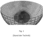
- Such an environment model based on polar coordinates is exemplified in Fig.1 where the intersection points of the Fig.1 shown grid model correspond to the projection points of the environment model. How to Fig.1 detects, the distance between the projection points also increases with increasing radial distance from the vehicle.
- the main disadvantage of this is that the virtual image of the vehicle's surroundings, and thus also the image subsequently displayed, does not have a constant resolution.
- the distance between the sampling points increases with increasing distance from the vehicle, which has a detrimental effect on the image subsequently generated, e.g. in the form of an increase in distortion artifacts.
- the "best" or highest sampling point resolution i.e. the smallest distance between the sampling points, is also achieved in an area of the virtual image for which no real image data is available at all, namely in the area below the vehicle. As is well known, no image data is displayed for this area; instead, a three-dimensional model of the vehicle is usually generated and shown in the displayed image.
- the method according to the invention is used to generate a virtual image of a vehicle environment.
- real images of the vehicle environment are captured using one or more cameras arranged on the vehicle.
- individual pixels i.e. in particular image data such as the color and brightness of individual pixels, are projected from the real images captured by the cameras onto projection points of a three-dimensional environmental model of the vehicle environment.
- the three-dimensional environmental model is to be understood in particular as a virtual model of the vehicle environment, according to the invention a shell-shaped projection surface formed from projection points onto which the image data is projected according to a predetermined algorithm and/or using so-called lookup tables, wherein the projection points are distributed in at least three spatial directions.
- the projection points of the three-dimensional environment model are arranged equidistantly in a first spatial direction and in a second spatial direction.
- the projection points are arranged equidistantly in relation to two of three orthogonal spatial directions of the three-dimensional space in which the three-dimensional environment model is defined or in which the projection points are distributed, ie in relation to at least one of the coordinate planes of three-dimensional space.
- the equidistant arrangement is understood to mean an arrangement of the projection points such that they are the same distance from one another in at least two spatial directions, i.e. in particular in at least two coordinate directions.
- the same distance between the projection points can be provided for both spatial directions, or different equidistant distances can be selected for the projection points in both spatial directions.
- a significant advantage of this arrangement of the projection points or of the resulting environment model is that, particularly with identical distances in both spatial directions, a constant image resolution is achieved for the virtual image in relation to the plane spanned by the two spatial directions. The resolution of the virtual image is therefore independent of the distance of the projection points from the vehicle, particularly compared to the known environment models.
- the position of the projection points in three-dimensional space is defined by means of Cartesian coordinates, i.e. preferably by means of x, y and z coordinates.
- Cartesian coordinates i.e. preferably by means of x, y and z coordinates.
- the projection points are arranged equidistantly with respect to the coordinate plane which corresponds to an assumed road surface in the environment model.
- the position of the road surface is to be understood as the position of the real standing plane of the vehicle assumed in the environment model.
- the projection points are thus arranged equidistantly in the two spatial directions, which in the environment model span the plane that corresponds to an assumed or virtual road surface.
- the size of the distance between the projection points in the first and/or the second spatial direction is defined as a function of at least one variable parameter.
- the distance between the projection points and thus the resolution of the virtual image can be easily adapted, for example to a desired image resolution or, for example, to the processor performance or vehicle speed.
- the position of the projection points in a third spatial direction is defined as a function of a distance of the projection points from the vehicle, in particular as a function of the horizontal or lateral distance from a virtual vehicle edge assumed in the environment model.
- the third spatial direction is preferably the third of three orthogonal spatial directions and preferably the distance of the projection points perpendicular to the assumed road surface.
- the position in the third spatial direction is the height of the projection points in relation to the assumed road surface in the virtual environment model.
- the position of the projection points in the third spatial direction can still be dependent on a given maximum Distance, ie depending on a limit value for the distance to the vehicle or to the edge of the vehicle, and/or depending on a predetermined gradient factor.
- a maximum value for the position of the projection points in the third spatial direction can be specified, in particular a maximum height of the projection points in the virtual environment model.
- the position or distribution of the projection points in the third spatial direction is preferably described by means of an exponential function within the scope of the method according to the invention.
- the definition of the position of the projection points in the third spatial direction as a function of one or more of the parameters mentioned above, and in particular by means of an exponential function, enables the provision of a dynamic, changeable model that can be adapted particularly easily to the respective application.
- the shell-shaped projection surface according to the invention created in this way can be adapted to the real world in a simple manner, i.e. by adjusting a few parameters.
- distances to objects in the vehicle environment can be measured and both the maximum extent (limit value for the distance to the vehicle) and the gradient factor of the side walls of the projection surface can be adapted to these object distances, in particular in order to reduce distortions of objects in the displayed image.
- At least one Area around the vehicle or around its virtual position in the environment model is defined, in particular a first area, wherein in this area, in particular for calculating the position of the projection points in the third spatial direction, the distance of a projection point from the vehicle corresponds to the lateral distance of the projection point from the edge of the vehicle, ie its distance in the first or second spatial direction.
- the first area preferably comprises the areas in front of and behind the vehicle and to the side, ie to the left and right, of the vehicle.
- At least one area around the vehicle or around its virtual position in the environment model is defined in the environment model, in particular a second area, wherein in this area, in particular for calculating the position of the projection points in the third spatial direction, the distance of a projection point from the edge of the vehicle corresponds to the radial distance of the projection point from a specific point, in particular from a vehicle center or vehicle corner point.
- the second area preferably comprises the areas front-left and front-right as well as rear-left and rear-right next to the vehicle.
- the invention further comprises a device for generating a virtual image of a vehicle environment, comprising one or more cameras which are arranged on the vehicle and which serve to capture real images from the vehicle environment.
- the device further comprises means for generating the virtual image by projecting the pixels from the real images captured by the cameras onto a defined three-dimensional environment model of the Vehicle environment.
- the means for generating the virtual image are designed according to the method according to the invention, in particular using a three-dimensional environment model according to one of the previously described embodiments.
- the invention further relates to a driver assistance system which comprises a device according to the invention or in which the method according to the invention is used.
- the invention comprises a vehicle in which such a driver assistance system or the device according to the invention is arranged.
- the method according to the invention Real images of the vehicle's surroundings are captured using one or more cameras arranged on the vehicle.
- individual pixels of the real images ie in particular image data such as the color and brightness of individual pixels
- projection points P i
- projection points can be understood as a synonym for the terms “sampling points” or “sampling points” also used in the prior art.
- the essential difference between the present invention and the methods known from the prior art is the design of the three-dimensional environment model used in the context of the method according to the invention, in particular the distribution or arrangement of the projection points (P i ) in the three-dimensional space (x,y,z space).
- FIGS. 2 and Figure 3 show a preferred embodiment of such an environmental model used in the context of the method according to the invention.
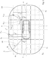
- Figure 2 shows the environment model used in the vertical plan view, ie from a bird's eye view.
- the positions of the projection points (P i ) of the three-dimensional environment model are defined by means of Cartesian coordinates x, y and z.
- the environment model is thus shown from the vertical z-direction onto the x-, y-coordinate plane (E xy ), whereby this plane (E xy ) in the environment model simultaneously corresponds to the assumed road surface or the standing plane of the vehicle.
- the projection points (P i ) are arranged equidistantly from one another in at least one first spatial direction (x) and one second spatial direction (y).
- the two spatial directions are the coordinate directions x and y, ie the projection points (P i ) are constantly at the same distance ( ⁇ x, ⁇ y) from one another in the x and y directions.
- the projection points (P i ) are thus arranged equidistantly from one another in relation to the coordinate plane (E xy ) which corresponds to the assumed road surface in the environmental model.
- the size of the distance ( ⁇ x, ⁇ y) between the projection points in the x and y directions can either be fixed or variably defined, in particular depending on one or more parameters, for example depending on the desired resolution of the virtual or displayed image, depending on the processor performance of the image processing unit and/or for example depending on the current driving speed.
- the position in the Z direction is defined according to the invention as a function of the distance (d Pi ) of the projection points (P i ) to the vehicle and as a function of other parameters.
- Figure 3 shows in this context a preferred embodiment for determining the position of the projection points (z Pi ) in the z-direction.
- the position (z Pi ) in the Z-direction is defined both as a function of the distance (d Pi ) to the vehicle and as a function of a limit value for the distance to the vehicle, ie a predetermined maximum distance (d max ) of the projection points (P i ) to the vehicle, as well as as a function of a predetermined gradient parameter (n).
- a maximum value or a limit value (z max ) is defined for the height of the environment model.
- the values d max , z max and n are preferably chosen to be identical for all projection points (P i ), whereas the distance (d Pi ) of the projection points (P i ) is preferably defined differently for individual areas around the vehicle.
- Fig.2 first areas are defined, namely the areas in front (V) and behind (H) the vehicle as well as the areas to the left (L) and right (R) of the vehicle, whereby in these areas the distance (d Pi ) of a projection point (P i,R ) from the vehicle corresponds to the lateral or vertical distance (d Pi,R ) of the projection point from the nearest virtual vehicle edge (K R ) in the x or y direction.
- second areas are defined, namely the front-left (VL) and front-right (VR) areas next to the vehicle and the rear-left (HL) and rear-right (HR) areas next to the vehicle, which can correspond in particular to the overlapping areas of cameras of a camera surround view system, i.e. their overlapping detection areas.
- the distance (d Pi ) of a projection point (P i,HR ) from the vehicle corresponds to the radial distance (d Pi,HR ) of the projection point (P i,HR ) from the nearest vehicle corner point (E HR ), i.e. from the node of the nearest vehicle edges.
- the three-dimensional environment model used in the present invention to generate the virtual image of the vehicle environment is shown in the Figures 2 and 3 shown in a highly simplified manner, in particular with only a few projection points (P i ) compared to the real application.
- the environment model can, for example when used for a driver assistance system in a vehicle, either be statically specified or, for example, be recalculated for each image in real time.
- the inventive The method can be implemented in particular by a computer program in a driver assistance system, which contains computer commands that can be executed by a microprocessor. In one possible embodiment, this program is stored on a data carrier or in a program memory.
Description
Die Erfindung betrifft ein Verfahren zur Erzeugung eines virtuellen Bildes einer Fahrzeugumgebung unter Verwendung eines dreidimensionalen Umgebungsmodells, insbesondere zum Einsatz in einem Fahrzeug, welches über ein Kamera-Surround-View-System verfügt.The invention relates to a method for generating a virtual image of a vehicle environment using a three-dimensional environment model, in particular for use in a vehicle which has a camera surround view system.
Fahrzeuge werden zunehmend mit Fahrerassistenzsystemen ausgerüstet, welche den Fahrer bei der Durchführung von Fahrmanövern unterstützen. Diese Fahrerassistenzsysteme enthalten zum Teil Kamera-Surround-View-Systeme, die es erlauben, dem Fahrer des Fahrzeugs die Fahrzeugumgebung anzuzeigen. Derartige Kamera-Surround-View-Systeme umfassen eine oder mehrere Fahrzeugkameras, welche reale Bilder der Fahrzeugumgebung liefern, die durch eine Datenverarbeitungseinheit des Kamera-Surround-View-Systems zu einem Umgebungsbild der Fahrzeugumgebung zusammengefügt werden. Das Bild der Fahrzeugumgebung wird dann dem Fahrer auf einer Anzeigeeinheit angezeigt. Hierzu müssen die von den Kameras des Kamera-Surround-View-Systems gewonnen realen Bilder der Fahrzeugumgebung zunächst auf Projektionspunkte eines virtuellen Umgebungsmodells der Fahrzeugumgebung projiziert werden. Anschließend kann aus der Perspektive einer virtuellen Kamera, auf das so erzeugte virtuelle Bild der Fahrzeugumgebung, wiederum das auf der Anzeigeeinheit angezeigte Bild berechnet werden. Die Position der virtuellen Kamera für die Berechnung des angezeigten Bildes kann dabei variiert werden, so dass je nach Bedarf bzw. je nach Fahrsituation dem Fahrer eine andere Darstellung der Fahrzeugumgebung angezeigt werden kann. Die Wahl des dreidimensionalen Umgebungsmodells, für die Projektion der realen Bilder sowie für die Erzeugung des virtuellen Bildes, ist dabei entscheidend für die Qualität des angezeigten Bildes.Vehicles are increasingly being equipped with driver assistance systems that support the driver in carrying out driving maneuvers. Some of these driver assistance systems contain camera surround view systems that allow the vehicle's surroundings to be shown to the driver of the vehicle. Such camera surround view systems comprise one or more vehicle cameras that provide real images of the vehicle's surroundings that are combined by a data processing unit of the camera surround view system to form an environmental image of the vehicle's surroundings. The image of the vehicle's surroundings is then shown to the driver on a display unit. To do this, the real images of the vehicle's surroundings obtained by the cameras of the camera surround view system must first be projected onto projection points of a virtual environmental model of the vehicle's surroundings. The image displayed on the display unit can then be calculated from the perspective of a virtual camera onto the virtual image of the vehicle's surroundings generated in this way. The position of the virtual camera for calculating the displayed image can be varied so that the driver can be shown a different representation of the vehicle's surroundings as required or depending on the driving situation. The choice of the three-dimensional environment model for the projection of the real Images as well as the generation of the virtual image is crucial for the quality of the displayed image.
Die Offenlegungsschrift
Weitere gattungsgemäße Verfahren sind aus den Offenlegungsschriften
Des Weiteren offenbart die Offenlegungsschrift
Ferner offenbart die Offenlegungsschrift
Herkömmliche kamerabasierte Fahrerassistenzsysteme projizieren Texturinformationen des Kamerasystems somit auf eine statische Projektionsfläche, vorzugsweise auf eine dreidimensionale Schalenfläche als Umgebungsmodell, wobei der Krümmungsradius mit zunehmendem Abstand vom Fahrzeug zunimmt, wie beispielsweise in der vorangehend genannten
Ein wesentlicher Nachteil der bislang verwendeten dreidimensionalen schalenförmigen Umgebungsmodelle bzw. Projektionsflächen ist jedoch, dass diese Modelle in der Regel mittels Polargleichungen bzw. mittels Polarkoordinaten beschrieben werden, insbesondere für den Projektionsalgorithmus, d.h. für die Umsetzung der Projektion der realen Bilddaten. Ein solches auf Polarkoordinaten basierendes Umgebungsmodell ist exemplarisch in
Es ist die Aufgabe der vorliegenden Erfindung, ein verbessertes Verfahren zur Erzeugung eines virtuellen Bildes einer Fahrzeugumgebung anzugeben, insbesondere unter Verwendung eines verbesserten dreidimensionalen Umgebungsmodells.It is the object of the present invention to provide an improved method for generating a virtual image of a vehicle environment, in particular using an improved three-dimensional environment model.
Diese Aufgabe wird durch die Gegenstände der unabhängigen Ansprüche gelöst. Weitere vorteilhafte Ausgestaltungen ergeben sich aus den abhängigen Ansprüchen.This object is achieved by the subject matter of the independent claims. Further advantageous embodiments emerge from the dependent claims.
Das erfindungsgemäße Verfahren dient zur Erzeugung eines virtuellen Bildes einer Fahrzeugumgebung. Dabei werden im Rahmen des Verfahrens mittels einer oder mehrerer am Fahrzeug angeordneter Kameras reale Bilder der Fahrzeugumgebung erfasst. Weiterhin werden einzelne Bildpunkte, d.h. insbesondere Bilddaten wie Farbe und Helligkeit einzelner Bildpunkte, aus den mittels der Kameras erfassten realen Bildern auf Projektionspunkte eines dreidimensionalen Umgebungsmodells der Fahrzeugumgebung projiziert. Unter dem dreidimensionalen Umgebungsmodell ist dabei insbesondere ein virtuelles Modell der Fahrzeugumgebung zu verstehen, erfindungsgemäß eine aus Projektionspunkten gebildete schalenförmige Projektionsfläche, auf die nach einem vorgegebenen Algorithmus und/oder mittels sogenannter Lookup-Tabellen die Bilddaten projiziert werden, wobei die Projektionspunkte in wenigstens drei Raumrichtungen verteilt angeordnet sind.The method according to the invention is used to generate a virtual image of a vehicle environment. In the process, real images of the vehicle environment are captured using one or more cameras arranged on the vehicle. Furthermore, individual pixels, i.e. in particular image data such as the color and brightness of individual pixels, are projected from the real images captured by the cameras onto projection points of a three-dimensional environmental model of the vehicle environment. The three-dimensional environmental model is to be understood in particular as a virtual model of the vehicle environment, according to the invention a shell-shaped projection surface formed from projection points onto which the image data is projected according to a predetermined algorithm and/or using so-called lookup tables, wherein the projection points are distributed in at least three spatial directions.
Erfindungsgemäß sind dabei die Projektionspunkte des dreidimensionalen Umgebungsmodells in eine erste Raumrichtung und in eine zweite Raumrichtung äquidistant angeordnet. Die Projektionspunkte sind dabei in Bezug zu zwei von drei orthogonalen Raumrichtungen des dreidimensionalen Raums, in dem das dreidimensionale Umgebungsmodell definiert ist bzw. in dem die Projektionspunkte verteilt angeordnet sind, äquidistant angeordnet, d.h. in Bezug zu wenigstens einer der Koordinatenebene des dreidimensionalen Raums. Unter der äquidistanten Anordnung ist dabei eine derartige Anordnung der Projektionspunkte zu verstehen, dass diese in wenigstens zwei Raumrichtungen, d.h. insbesondere in wenigstens zwei Koordinatenrichtungen, gleiche Abstände zueinander aufweisen. Dabei kann für beiden Raumrichtungen derselbe Abstand für die Projektionspunkte zueinander vorgesehen sein oder es können in beide Raumrichtungen unterschiedliche äquidistante Abstande für die Projektionspunkte gewählt werden. Ein wesentlicher Vorteil dieser Anordnung der Projektionspunkte bzw. des sich daraus ergebenden Umgebungsmodells besteht darin, insbesondere bei identischen Abständen in beide Raumrichtungen, dass für das virtuelle Bild eine konstante Bildauflösung in Bezug zu der durch die beiden Raumrichtungen aufgespannten Ebene erreicht wird. Die Auflösung des virtuellen Bildes ist somit, insbesondere gegenüber den bekannten Umgebungsmodellen, unabhängig vom Abstand der Projektionspunkte zum Fahrzeug.According to the invention, the projection points of the three-dimensional environment model are arranged equidistantly in a first spatial direction and in a second spatial direction. The projection points are arranged equidistantly in relation to two of three orthogonal spatial directions of the three-dimensional space in which the three-dimensional environment model is defined or in which the projection points are distributed, ie in relation to at least one of the coordinate planes of three-dimensional space. The equidistant arrangement is understood to mean an arrangement of the projection points such that they are the same distance from one another in at least two spatial directions, i.e. in particular in at least two coordinate directions. The same distance between the projection points can be provided for both spatial directions, or different equidistant distances can be selected for the projection points in both spatial directions. A significant advantage of this arrangement of the projection points or of the resulting environment model is that, particularly with identical distances in both spatial directions, a constant image resolution is achieved for the virtual image in relation to the plane spanned by the two spatial directions. The resolution of the virtual image is therefore independent of the distance of the projection points from the vehicle, particularly compared to the known environment models.
Gemäß einer bevorzugten Ausgestaltung des erfindungsgemäßen Verfahrens ist die Position der Projektionspunkte im dreidimensionalen Raum mittels kartesischer Koordinaten definiert, d.h. vorzugweise mittels x-, y- und z-Koordinaten. Hierdurch lässt sich, insbesondere gegenüber einer Verwendung von Polarkoordinaten, auf einfache Weise eine äquidistante Anordnung der Projektionspunkte bezüglich wenigstens zweier Koordinatenrichtungen definieren, beispielsweise durch fest definierte Abstände zwischen den Projektionspunkten in x- und y-Richtung.According to a preferred embodiment of the method according to the invention, the position of the projection points in three-dimensional space is defined by means of Cartesian coordinates, i.e. preferably by means of x, y and z coordinates. This makes it easy to define an equidistant arrangement of the projection points with respect to at least two coordinate directions, particularly compared to the use of polar coordinates, for example by means of fixed distances between the projection points in the x and y directions.
Erfindungsgemäß sind die Projektionspunkte in Bezug zu derjenigen Koordinatenebene äquidistant angeordnet, welche im Umgebungsmodell einer angenommenen Fahrbahnoberfläche entspricht. Unter der Fahrbahnoberfläche ist dabei die im Umgebungsmodell angenommene Lage der realen Standebene des Fahrzeugs zu verstehen. Gemäß dieser Ausgestaltung sind die Projektionspunkte somit in die beiden Raumrichtungen äquidistant angeordnet, welche im Umgebungsmodell die Ebene aufspannen, welche einer angenommenen bzw. der virtuellen Fahrbahnoberfläche entspricht.According to the invention, the projection points are arranged equidistantly with respect to the coordinate plane which corresponds to an assumed road surface in the environment model. The position of the road surface is to be understood as the position of the real standing plane of the vehicle assumed in the environment model. According to this design, the projection points are thus arranged equidistantly in the two spatial directions, which in the environment model span the plane that corresponds to an assumed or virtual road surface.
Gemäß einer weiteren bevorzugten Ausgestaltung des erfindungsgemäßen Verfahrens ist die Größe des Abstands der Projektionspunkte in die erste und/oder die zweite Raumrichtung in Abhängigkeit wenigstens eines veränderbaren Parameters definiert. Gemäß dieser Ausgestaltung kann der Abstand der Projektionspunkte und damit die Auflösung des virtuellen Bildes auf einfache Weise, beispielsweise an eine gewünschte Bildauflösung oder beispielsweise auch an die Prozessorleistung oder Fahrzeuggeschwindigkeit, angepasst werden.According to a further preferred embodiment of the method according to the invention, the size of the distance between the projection points in the first and/or the second spatial direction is defined as a function of at least one variable parameter. According to this embodiment, the distance between the projection points and thus the resolution of the virtual image can be easily adapted, for example to a desired image resolution or, for example, to the processor performance or vehicle speed.
Erfindungsgemäß ist die Position der Projektionspunkte in eine dritte Raumrichtung in Abhängigkeit eines Abstands der Projektionspunkte vom Fahrzeug definiert, insbesondere in Abhängigkeit des Abstands horizontal bzw. lateral von einer im Umgebungsmodell angenommenen virtuellen Fahrzeugkante. Bei der dritten Raumrichtung handelt es sich dabei vorzugweise um die dritte von drei orthogonalen Raumrichtungen sowie vorzugsweise um den Abstand der Projektionspunkte senkrecht zur angenommenen Fahrbahnoberfläche. Mit anderen Worten handelt es sich bei der Position in die dritte Raumrichtung um die Höhe der Projektionspunkte in Bezug zur angenommenen Fahrbahnoberfläche im virtuellen Umgebungsmodell.According to the invention, the position of the projection points in a third spatial direction is defined as a function of a distance of the projection points from the vehicle, in particular as a function of the horizontal or lateral distance from a virtual vehicle edge assumed in the environment model. The third spatial direction is preferably the third of three orthogonal spatial directions and preferably the distance of the projection points perpendicular to the assumed road surface. In other words, the position in the third spatial direction is the height of the projection points in relation to the assumed road surface in the virtual environment model.
Die Position der Projektionspunkte in die dritte Raumrichtung kann dabei weiterhin in Abhängigkeit eines vorgegebenen maximalen Abstandes, d.h. in Abhängigkeit eines Grenzwerts für den Abstand zum Fahrzeug bzw. zur Fahrzeugkante, und/oder in Abhängigkeit eines vorgegebenen Steigungsfaktors definiert sein.The position of the projection points in the third spatial direction can still be dependent on a given maximum Distance, ie depending on a limit value for the distance to the vehicle or to the edge of the vehicle, and/or depending on a predetermined gradient factor.
Weiterhin kann ein Maximalwert für die Position der Projektionspunkte in die dritte Raumrichtung vorgegeben sein, insbesondere eine maximale Höhe der Projektionspunkte im virtuellen Umgebungsmodell.Furthermore, a maximum value for the position of the projection points in the third spatial direction can be specified, in particular a maximum height of the projection points in the virtual environment model.
Die Position bzw. die Verteilung der Projektionspunkte in die dritte Raumrichtung wird dabei im Rahmen des erfindungsgemäßen Verfahrens bevorzugt mittels einer Exponentialfunktion beschrieben.The position or distribution of the projection points in the third spatial direction is preferably described by means of an exponential function within the scope of the method according to the invention.
Die Definition der Position der Projektionspunkte in die dritte Raumrichtung in Abhängigkeit eines oder mehrerer der vorangehend genannten Parameter, sowie insbesondere mittels einer Exponentialfunktion, ermöglicht dabei die Bereitstellung eines dynamischen veränderbaren Modells, das besonders einfach an den jeweiligen Anwendungsfall angepasst werden kann. Beispielsweise kann die so erzeugte erfindungsgemäße schalenförmige Projektionsfläche auf einfache Weise, d.h. durch Anpassung weniger Parameter, an die reale Welt angepasst werden. Hierzu können z.B. Abstände zu Objekten in der Fahrzeugumgebung gemessen und sowohl die maximale Ausdehnung (Grenzwert für den Abstand zum Fahrzeug) und der Steigungsfaktor der Seitenwände der Projektionsfläche an diese Objektdistanzen angepasst werden, insbesondere um Verzerrungen von Objekten im angezeigten Bild zu reduzieren.The definition of the position of the projection points in the third spatial direction as a function of one or more of the parameters mentioned above, and in particular by means of an exponential function, enables the provision of a dynamic, changeable model that can be adapted particularly easily to the respective application. For example, the shell-shaped projection surface according to the invention created in this way can be adapted to the real world in a simple manner, i.e. by adjusting a few parameters. For this purpose, for example, distances to objects in the vehicle environment can be measured and both the maximum extent (limit value for the distance to the vehicle) and the gradient factor of the side walls of the projection surface can be adapted to these object distances, in particular in order to reduce distortions of objects in the displayed image.
Gemäß einer weiteren bevorzugten Ausgestaltung des erfindungsgemäßen Verfahrens ist im Umgebungsmodell wenigstens ein Bereich um das Fahrzeug bzw. um dessen virtuelle Position im Umgebungsmodell definiert, insbesondere ein erster Bereich, wobei in diesem Bereich, insbesondere für die Berechnung der Position der Projektionspunkte in die dritte Raumrichtung, der Abstand eines Projektionspunktes vom Fahrzeug dem lateralen Abstand des Projektionspunktes von der Fahrzeugkante entspricht, d.h. dessen Abstand in die erste oder zweite Raumrichtung. Bei dem ersten Bereich handelt es sich vorzugsweise um die Bereiche vor und hinter dem Fahrzeug sowie seitlich, d.h. links und rechts, neben dem Fahrzeug.According to a further preferred embodiment of the method according to the invention, at least one Area around the vehicle or around its virtual position in the environment model is defined, in particular a first area, wherein in this area, in particular for calculating the position of the projection points in the third spatial direction, the distance of a projection point from the vehicle corresponds to the lateral distance of the projection point from the edge of the vehicle, ie its distance in the first or second spatial direction. The first area preferably comprises the areas in front of and behind the vehicle and to the side, ie to the left and right, of the vehicle.
Gemäß einer weiteren bevorzugten Ausgestaltung des erfindungsgemäßen Verfahrens ist im Umgebungsmodell wenigstens ein Bereich um das Fahrzeug bzw. um dessen virtuelle Position im Umgebungsmodell definiert, insbesondere ein zweiter Bereich, wobei in diesem Bereich, insbesondere für die Berechnung der Position der Projektionspunkte in die dritte Raumrichtung, der Abstand eines Projektionspunktes von der Fahrzeugkante dem radialen Abstand des Projektionspunktes von einem bestimmten Punkt entspricht, insbesondere von einem Fahrzeugmittelpunkt oder Fahrzeugeckpunkt. Bei dem zweiten Bereich handelt es sich dabei vorzugsweise um die Bereiche vorne-links und vorne-rechts sowie hinten-links und hinten-rechts neben dem Fahrzeug.According to a further preferred embodiment of the method according to the invention, at least one area around the vehicle or around its virtual position in the environment model is defined in the environment model, in particular a second area, wherein in this area, in particular for calculating the position of the projection points in the third spatial direction, the distance of a projection point from the edge of the vehicle corresponds to the radial distance of the projection point from a specific point, in particular from a vehicle center or vehicle corner point. The second area preferably comprises the areas front-left and front-right as well as rear-left and rear-right next to the vehicle.
Die Erfindung umfasst weiterhin eine Vorrichtung zur Erzeugung eines virtuellen Bildes einer Fahrzeugumgebung, umfassend eine oder mehrere Kameras, die am Fahrzeug angeordnet sind und die zur Erfassung realer Bilder aus der Fahrzeugumgebung dienen. Die Vorrichtung umfasst weiterhin Mittel zur Erzeugung des virtuellen Bildes mittels Projektion der Bildpunkte aus den mittels der Kameras erfassten realen Bildern auf ein definiertes dreidimensionales Umgebungsmodell der Fahrzeugumgebung. Erfindungsgemäß sind die Mittel dabei zur Erzeugung des virtuellen Bildes gemäß dem erfindungsgemäßen Verfahren ausgebildet, insbesondere unter Verwendung eines dreidimensionalen Umgebungsmodells gemäß einer der vorangehend beschriebenen Ausgestaltungen.The invention further comprises a device for generating a virtual image of a vehicle environment, comprising one or more cameras which are arranged on the vehicle and which serve to capture real images from the vehicle environment. The device further comprises means for generating the virtual image by projecting the pixels from the real images captured by the cameras onto a defined three-dimensional environment model of the Vehicle environment. According to the invention, the means for generating the virtual image are designed according to the method according to the invention, in particular using a three-dimensional environment model according to one of the previously described embodiments.
Die Erfindung betrifft weiterhin ein Fahrerassistenzsystem, welches eine erfindungsgemäße Vorrichtung umfasst oder in dem das erfindungsgemäße Verfahren verwendet wird.The invention further relates to a driver assistance system which comprises a device according to the invention or in which the method according to the invention is used.
Weiterhin umfasst die Erfindung ein Fahrzeug in dem ein solches Fahrerassistenzsystem oder die erfindungsgemäße Vorrichtung angeordnet sind.Furthermore, the invention comprises a vehicle in which such a driver assistance system or the device according to the invention is arranged.
Die Erfindung wird nachfolgend anhand eines Ausführungsbeispiels näher erläutert, aus dem sich weitere Vorteile und Anwendungsmöglichkeiten ergeben.The invention is explained in more detail below using an embodiment from which further advantages and possible applications arise.
Es zeigen
- Figur 1:
- ein aus dem Stand der Technik bekanntes und auf Polarkoordinaten basierendes schalenförmiges Umgebungsmodell.
- Figur 2:
- ein Beispiel für ein im Rahmen des erfindungsgemäßen Verfahren verwendetes dreidimensionales Umgebungsmodell in einer Draufsicht.
- Figur 3:
- die erfindungsgemäße Anordnung der Projektionspunkte in eine dritte Raumrichtung.
- Figure 1:
- a shell-shaped environment model known from the state of the art and based on polar coordinates.
- Figure 2:
- an example of a three-dimensional environmental model used in the method according to the invention in a plan view.
- Figure 3:
- the inventive arrangement of the projection points in a third spatial direction.
Wie bereits bei den aus dem Stand der Technik bekannten Verfahren, werden im Rahmen des erfindungsgemäßen Verfahrens mittels einer oder mehrerer am Fahrzeug angeordneter Kameras reale Bilder der Fahrzeugumgebung erfasst.As with the methods known from the prior art, the method according to the invention Real images of the vehicle's surroundings are captured using one or more cameras arranged on the vehicle.
Weiterhin werden im Rahmen des erfindungsgemäßen Verfahrens einzelne Bildpunkte der realen Bilder, d.h. insbesondere Bilddaten wie die Farbe und Helligkeit einzelner Bildpunkte, auf Projektionspunkte (Pi) eines dreidimensionalen Umgebungsmodells der Fahrzeugumgebung projiziert. Der Begriff "Projektionspunkte" kann dabei synonym zu den im Stand der Technik ebenfalls verwendeten Begriffen "Abtastpunkte" oder "Sampling Points" verstanden werden.Furthermore, within the scope of the method according to the invention, individual pixels of the real images, ie in particular image data such as the color and brightness of individual pixels, are projected onto projection points (P i ) of a three-dimensional model of the vehicle's surroundings. The term "projection points" can be understood as a synonym for the terms "sampling points" or "sampling points" also used in the prior art.
Der wesentliche Unterschied der vorliegenden Erfindung zu den aus dem Stand der Technik bekannten Verfahren ist die Ausgestaltung des im Rahmen des erfindungsgemäßen Verfahrens verwendeten dreidimensionalen Umgebungsmodells, insbesondere die Verteilung bzw. Anordnung der Projektionspunkte (Pi) im dreidimensionalen Raum (x,y,z-Raum).The essential difference between the present invention and the methods known from the prior art is the design of the three-dimensional environment model used in the context of the method according to the invention, in particular the distribution or arrangement of the projection points (P i ) in the three-dimensional space (x,y,z space).
Die
Die Projektionspunkte (Pi) sind erfindungsgemäß in wenigstens eine erste Raumrichtung (x) und eine zweite Raumrichtung (y) äquidistant zueinander angeordnet. Im vorliegenden Ausführungsbeispiel handelt es sich bei den beiden Raumrichtungen um die Koordinatenrichtungen x und y, d.h. die Projektionspunkte (Pi) weisen in x- und in y-Richtung konstant gleiche Abstände (Δx, Δy) zueinander auf. Die Projektionspunkte (Pi) sind im vorliegenden Beispiel somit in Bezug zu derjenigen Koordinatenebene (Exy) äquidistant zueinander angeordnet, welche im Umgebungsmodell der angenommenen Fahrbahnoberfläche entspricht.According to the invention, the projection points (P i ) are arranged equidistantly from one another in at least one first spatial direction (x) and one second spatial direction (y). In the present exemplary embodiment, the two spatial directions are the coordinate directions x and y, ie the projection points (P i ) are constantly at the same distance (Δx, Δy) from one another in the x and y directions. In the present example, the projection points (P i ) are thus arranged equidistantly from one another in relation to the coordinate plane (E xy ) which corresponds to the assumed road surface in the environmental model.
Die Größe des Abstands (Δx, Δy) der Projektionspunkte in x- und y-Richtung zueinander kann dabei erfindungsgemäß entweder fest vorgegeben oder variabel definiert sein, insbesondere in Abhängigkeit eines oder mehrerer Parameter, beispielsweise in Abhängigkeit der gewünschten Auflösung des virtuellen bzw. des angezeigten Bildes, in Abhängigkeit der Prozessorleistung der Bildverarbeitungseinheit und/oder beispielsweise in Abhängigkeit der aktuellen Fahrgeschwindigkeit.According to the invention, the size of the distance (Δx, Δy) between the projection points in the x and y directions can either be fixed or variably defined, in particular depending on one or more parameters, for example depending on the desired resolution of the virtual or displayed image, depending on the processor performance of the image processing unit and/or for example depending on the current driving speed.
Die Position der Projektionspunkte (Pi) in die dritte Raumrichtung (z), welche erfindungsgemäß der z-Richtung und damit der Höhe der Projektionspunkte (Pi) über der angenommenen Fahrbahnoberfläche entspricht, nimmt im vorliegenden Ausführungsbeispiel mit zunehmenden Abstand (dPi) zum Fahrzeug zu, so dass das Umgebungsmodell, wie in
Die z-Koordinate bzw. die Höhe (zPi) der Projektionspunkte ergibt sich somit allgemein gemäß der Formel ![]()
![]()
Dabei sind die Werte dmax, zmax und n vorzugsweise für alle Projektionspunkte (Pi) identisch gewählt, wohingegen der Abstand (dPi) der Projektionspunkte (Pi) für einzelne Bereiche um das Fahrzeug bevorzugt unterschiedlich definiert ist.The values d max , z max and n are preferably chosen to be identical for all projection points (P i ), whereas the distance (d Pi ) of the projection points (P i ) is preferably defined differently for individual areas around the vehicle.
Im vorliegenden Beispiel sind dazu gemäß ![]()
![]()
Weiterhin sind im vorliegenden Beispiel zweite Bereiche festgelegt, nämlich die Bereich vorne-links (VL) und vorne-rechts (VR) neben dem Fahrzeug sowie die Bereiche hinten-links (HL) und hinten-rechts (HR) neben dem Fahrzeug, welche insbesondere den Überlappungsbereichen von Kameras eines Kamera-Surround-View-Systems entsprechen können, d.h. deren überlappenden Erfassungsbereichen. In diesen Bereichen entspricht der Abstand (dPi) eines Projektionspunktes (Pi,HR) vom Fahrzeug dem radialen Abstand (dPi,HR) des Projektionspunktes (Pi,HR) vom nächstgelegenen Fahrzeugeckpunkt (EHR), d.h. vom Knotenpunkt der nächstgelegenen Fahrzeugkanten. Demnach gilt in diesen Bereichen, für die Berechnung der Höhe (zPi), ein Abstand (dPi) der Projektionspunkte (Pi) gemäß der folgenden Formel (hier beispielhaft angegeben für einen beliebigen Projektionspunkt (Pi,HR) im Bereich (HR) hinten-rechts neben dem Fahrzeug) ![]()
![]()
Das dreidimensionale Umgebungsmodell, welches im Rahmen der vorliegenden Erfindung zur Erzeugung des virtuellen Bildes der Fahrzeugumgebung verwendet wird, ist in den
Claims (10)
- Method for generating a virtual image of a vehicle environment, wherein- real images of the vehicle environment are recorded by means of one or more cameras arranged at the vehicle, and- individual image points from the real images which are recorded by means of the cameras are projected onto projection points (Pi) of a three-dimensional environment model of the vehicle environment in order to generate the virtual image, wherein the projection points (Pi) form a bowl-type projection surface, wherein- the projection points (Pi) are arranged equidistantly from one another in a first spatial direction (x) and a second spatial direction (y), which is orthogonal to the first spatial direction, with the result that a constant image resolution with respect to the coordinate plane (Exy), which is defined by the two spatial directions (x, y) and corresponds to a driving surface in the environment model, is achieved for the virtual image,wherein the position (zPi) of the projection points (Pi) in a third spatial direction (z), which corresponds to the height of the projection points (Pi) with respect to the driving surface in the environment model, is defined in dependence on a distance (dPi) from the vehicle in the environment model.
- Method according to Claim 1, characterized in that the position of the projection points (Pi) in the three-dimensional space is defined by using Cartesian coordinates.
- Method according to either of Claims 1 or 2, characterized in that the magnitude of the equidistant distances (Δx; Δy) of the projection points (Pi) in the first and/or in the second spatial direction (x, y) is defined in dependence on at least one variable parameter.
- Method according to any of the preceding claims, characterized in that the position (zPi) of the projection points (Pi) in the third spatial direction (z) is furthermore defined in dependence on a specified limit value (dmax) for the distance (dpi) from the vehicle and/or in dependence on a specified slope parameter (n).
- Method according to any of the preceding claims, characterized in that furthermore a maximum value (zmax) for the position (zPi) of the projection points (Pi) in the third spatial direction (z) is specified for the calculation of the environment model.
- Method according to any of the preceding claims, characterized in that at least one first region (V, H, L, R) around the vehicle is defined in the environment model, wherein the distance (dPi) of the projection points (Pi) in this region from the vehicle corresponds to the lateral distance (dPi,R) of the projection points (Pi,R) in this region from a virtual vehicle edge (KR).
- Method according to any of the preceding claims, characterized in that at least one second region (VL, VR, HL, HR) around the vehicle is defined in the environment model, wherein the distance (dPi) of the projection points (Pi) in this region from the vehicle corresponds to the radial distance (dPi,HR) of the projection points (dPi,HR) in this region from a vehicle corner point (EHR), the vehicle corner point (EHR) being a node point of the nearest vehicle edges.
- Apparatus for generating a virtual image of a vehicle environment, comprising- one or more cameras arranged at the vehicle for recording real images of the vehicle environment, and- means for generating the virtual image by means of projection of image points from the real images recorded by means of the camera onto projection points (Pi) of a three-dimensional environment model of the vehicle environment,characterized in that
the means for generating the virtual image are designed for carrying out a method according to any of the preceding claims. - Driver assistance system comprising an apparatus according to Claim 8 or designed for carrying out a method according to any of Claims 1-7.
- Vehicle comprising an apparatus according to Claim 8 or a driver assistance system according to Claim 9.
Applications Claiming Priority (2)
| Application Number | Priority Date | Filing Date | Title |
|---|---|---|---|
| DE102015210738 | 2015-06-11 | ||
| PCT/DE2016/200220 WO2016198059A1 (en) | 2015-06-11 | 2016-05-11 | Method for generating a virtual image of vehicle surroundings |
Publications (2)
| Publication Number | Publication Date |
|---|---|
| EP3308361A1 EP3308361A1 (en) | 2018-04-18 |
| EP3308361B1 true EP3308361B1 (en) | 2024-04-10 |
Family
ID=56549993
Family Applications (1)
| Application Number | Title | Priority Date | Filing Date |
|---|---|---|---|
| EP16742156.9A Active EP3308361B1 (en) | 2015-06-11 | 2016-05-11 | Method for generating a virtual image of vehicle surroundings |
Country Status (5)
| Country | Link |
|---|---|
| US (1) | US10412359B2 (en) |
| EP (1) | EP3308361B1 (en) |
| JP (1) | JP6975642B2 (en) |
| DE (1) | DE112016001048A5 (en) |
| WO (1) | WO2016198059A1 (en) |
Families Citing this family (6)
| Publication number | Priority date | Publication date | Assignee | Title |
|---|---|---|---|---|
| WO2018155670A1 (en) * | 2017-02-27 | 2018-08-30 | パナソニック インテレクチュアル プロパティ コーポレーション オブ アメリカ | Image distribution method, image display method, image distribution device and image display device |
| US10031526B1 (en) * | 2017-07-03 | 2018-07-24 | Baidu Usa Llc | Vision-based driving scenario generator for autonomous driving simulation |
| GB2573792B (en) | 2018-05-17 | 2022-11-09 | Denso Corp | Surround monitoring system for vehicles |
| JP7208356B2 (en) * | 2018-09-26 | 2023-01-18 | コーヒレント・ロジックス・インコーポレーテッド | Generating Arbitrary World Views |
| GB2581191B (en) * | 2019-02-08 | 2022-02-16 | Jaguar Land Rover Ltd | Image system for a vehicle |
| US10926715B1 (en) * | 2019-06-13 | 2021-02-23 | Vidal M. Soler | Vehicle camera system |
Family Cites Families (15)
| Publication number | Priority date | Publication date | Assignee | Title |
|---|---|---|---|---|
| JP3871614B2 (en) * | 2002-06-12 | 2007-01-24 | 松下電器産業株式会社 | Driving assistance device |
| US8855405B2 (en) * | 2003-04-30 | 2014-10-07 | Deere & Company | System and method for detecting and analyzing features in an agricultural field for vehicle guidance |
| JP5292874B2 (en) * | 2007-12-17 | 2013-09-18 | 富士通株式会社 | VEHICLE IMAGE PROCESSING DEVICE, VEHICLE IMAGE PROCESSING PROGRAM, AND VEHICLE IMAGE PROCESSING METHOD |
| DE102008036009B4 (en) | 2008-03-28 | 2018-03-22 | Volkswagen Ag | Method for collision protection of a motor vehicle and parking garage assistant |
| JP5124671B2 (en) * | 2011-06-07 | 2013-01-23 | 株式会社小松製作所 | Work vehicle perimeter monitoring device |
| KR101265667B1 (en) * | 2011-06-21 | 2013-05-22 | ㈜베이다스 | Device for 3d image composition for visualizing image of vehicle around and method therefor |
| US10793067B2 (en) | 2011-07-26 | 2020-10-06 | Magna Electronics Inc. | Imaging system for vehicle |
| DE102012203523A1 (en) | 2012-03-06 | 2013-09-12 | Bayerische Motoren Werke Aktiengesellschaft | Method for processing image data of cameras mounted in vehicle, involves determining image data to be signaled from view of virtual camera on surface of three-dimensional environment model |
| US9846960B2 (en) * | 2012-05-31 | 2017-12-19 | Microsoft Technology Licensing, Llc | Automated camera array calibration |
| US9330501B2 (en) * | 2012-08-20 | 2016-05-03 | Autodesk, Inc. | Systems and methods for augmenting panoramic image data with performance related data for a building |
| JP5911775B2 (en) | 2012-08-21 | 2016-04-27 | 富士通テン株式会社 | Image generation apparatus, image display system, and image generation method |
| DE102012219735A1 (en) | 2012-10-29 | 2014-04-30 | Bayerische Motoren Werke Aktiengesellschaft | Method for image processing of data of images detected by cameras arranged at e.g. outer side of vehicle, involves adapting image data to be signaled such that hidden object is perceptible on image to be signaled |
| US8892358B2 (en) | 2013-03-14 | 2014-11-18 | Robert Bosch Gmbh | System and method for distortion correction in three-dimensional environment visualization |
| JP6257978B2 (en) * | 2013-09-19 | 2018-01-10 | 株式会社デンソーテン | Image generation apparatus, image display system, and image generation method |
| DE102013220005A1 (en) | 2013-10-02 | 2015-04-02 | Continental Automotive Gmbh | Method and device for displaying the environment of a vehicle and driver assistance system |
-
2016
- 2016-05-11 US US15/735,519 patent/US10412359B2/en active Active
- 2016-05-11 DE DE112016001048.6T patent/DE112016001048A5/en active Pending
- 2016-05-11 EP EP16742156.9A patent/EP3308361B1/en active Active
- 2016-05-11 JP JP2017558429A patent/JP6975642B2/en active Active
- 2016-05-11 WO PCT/DE2016/200220 patent/WO2016198059A1/en active Application Filing
Also Published As
| Publication number | Publication date |
|---|---|
| JP6975642B2 (en) | 2021-12-01 |
| EP3308361A1 (en) | 2018-04-18 |
| US10412359B2 (en) | 2019-09-10 |
| JP2018520411A (en) | 2018-07-26 |
| DE112016001048A5 (en) | 2017-12-21 |
| US20180176533A1 (en) | 2018-06-21 |
| WO2016198059A1 (en) | 2016-12-15 |
Similar Documents
| Publication | Publication Date | Title |
|---|---|---|
| EP3308361B1 (en) | Method for generating a virtual image of vehicle surroundings | |
| EP3140813B1 (en) | Method and device for the distortion-free display of an area surrounding a vehicle | |
| DE102014209137B4 (en) | Method and device for calibrating a camera system of a motor vehicle | |
| DE102014222617B4 (en) | Vehicle detection method and vehicle detection system | |
| DE112013004103B4 (en) | Method and apparatus for generating a disparity card | |
| DE202017007675U1 (en) | Computer program product with a computer program for processing visual data of a road surface | |
| EP3117399B1 (en) | Method for assembling single images that have been taken from different positions by a camera system to form a joint image | |
| DE102017211395A1 (en) | Method of supporting a coupling process and support system | |
| DE102012223373A1 (en) | Apparatus and method for correcting image distortion from a rear camera | |
| DE102015202863A1 (en) | Method and device for the distortion-free display of a vehicle environment of a vehicle | |
| DE102016104730A1 (en) | Method for detecting an object along a road of a motor vehicle, computing device, driver assistance system and motor vehicle | |
| DE102016124978A1 (en) | Virtual representation of an environment of a motor vehicle in a driver assistance system with a plurality of projection surfaces | |
| DE102019105630B4 (en) | Display control device, vehicle surroundings display system and computer program | |
| DE102019132996A1 (en) | Estimating a three-dimensional position of an object | |
| EP1352363B1 (en) | Method and device for compensating for the maladjustment of an image producing device | |
| DE102014225848A1 (en) | Apparatus, method and computer readable medium for correcting an interpolation coefficient for stereo matching | |
| EP3420533B1 (en) | Method for calibrating an optical measurement set-up | |
| EP3073446B1 (en) | Method for representing the surroundings of a vehicle | |
| EP2996327A2 (en) | Surround view system for vehicles with attachments | |
| DE102014219418B4 (en) | Process for the stereo rectification of stereo camera images and driver assistance system | |
| DE102010034127A1 (en) | Method for displaying images on a display device in a motor vehicle, driver assistance system and motor vehicle | |
| DE102017104957A1 (en) | Method for determining a movement of mutually corresponding pixels in an image sequence from a surrounding area of a motor vehicle, evaluation device, driver assistance system and motor vehicle | |
| EP3465608B1 (en) | Method and device for determining a transfer between two display images, and vehicle | |
| DE102020107949A1 (en) | Field of view assist image generation apparatus and image conversion method | |
| EP3973511A1 (en) | Method for generating an image of vehicle surroundings, and apparatus for generating an image of vehicle surroundings |
Legal Events
| Date | Code | Title | Description |
|---|---|---|---|
| STAA | Information on the status of an ep patent application or granted ep patent |
Free format text: STATUS: THE INTERNATIONAL PUBLICATION HAS BEEN MADE |
|
| PUAI | Public reference made under article 153(3) epc to a published international application that has entered the european phase |
Free format text: ORIGINAL CODE: 0009012 |
|
| STAA | Information on the status of an ep patent application or granted ep patent |
Free format text: STATUS: REQUEST FOR EXAMINATION WAS MADE |
|
| 17P | Request for examination filed |
Effective date: 20180111 |
|
| AK | Designated contracting states |
Kind code of ref document: A1 Designated state(s): AL AT BE BG CH CY CZ DE DK EE ES FI FR GB GR HR HU IE IS IT LI LT LU LV MC MK MT NL NO PL PT RO RS SE SI SK SM TR |
|
| AX | Request for extension of the european patent |
Extension state: BA ME |
|
| DAV | Request for validation of the european patent (deleted) | ||
| DAX | Request for extension of the european patent (deleted) | ||
| RAP1 | Party data changed (applicant data changed or rights of an application transferred) |
Owner name: CONTI TEMIC MICROELECTRONIC GMBH |
|
| STAA | Information on the status of an ep patent application or granted ep patent |
Free format text: STATUS: EXAMINATION IS IN PROGRESS |
|
| STAA | Information on the status of an ep patent application or granted ep patent |
Free format text: STATUS: EXAMINATION IS IN PROGRESS |
|
| 17Q | First examination report despatched |
Effective date: 20201016 |
|
| RAP1 | Party data changed (applicant data changed or rights of an application transferred) |
Owner name: CONTI TEMIC MICROELECTRONIC GMBH |
|
| STAA | Information on the status of an ep patent application or granted ep patent |
Free format text: STATUS: EXAMINATION IS IN PROGRESS |
|
| RAP1 | Party data changed (applicant data changed or rights of an application transferred) |
Owner name: CONTINENTAL AUTONOMOUS MOBILITY GERMANY GMBH |
|
| P01 | Opt-out of the competence of the unified patent court (upc) registered |
Effective date: 20230522 |
|
| GRAP | Despatch of communication of intention to grant a patent |
Free format text: ORIGINAL CODE: EPIDOSNIGR1 |
|
| STAA | Information on the status of an ep patent application or granted ep patent |
Free format text: STATUS: GRANT OF PATENT IS INTENDED |
|
| INTG | Intention to grant announced |
Effective date: 20231201 |
|
| GRAS | Grant fee paid |
Free format text: ORIGINAL CODE: EPIDOSNIGR3 |
|
| GRAA | (expected) grant |
Free format text: ORIGINAL CODE: 0009210 |
|
| STAA | Information on the status of an ep patent application or granted ep patent |
Free format text: STATUS: THE PATENT HAS BEEN GRANTED |
|
| P02 | Opt-out of the competence of the unified patent court (upc) changed |
Effective date: 20240207 |
|
| AK | Designated contracting states |
Kind code of ref document: B1 Designated state(s): AL AT BE BG CH CY CZ DE DK EE ES FI FR GB GR HR HU IE IS IT LI LT LU LV MC MK MT NL NO PL PT RO RS SE SI SK SM TR |
|
| REG | Reference to a national code |
Ref country code: GB Ref legal event code: FG4D Free format text: NOT ENGLISH |