EP3307991B2 - Anordnung mit einem abgasgehäuse und einem nachgeschalteten rotationssymmetrischen teil - Google Patents
Anordnung mit einem abgasgehäuse und einem nachgeschalteten rotationssymmetrischen teil Download PDFInfo
- Publication number
- EP3307991B2 EP3307991B2 EP16735912.4A EP16735912A EP3307991B2 EP 3307991 B2 EP3307991 B2 EP 3307991B2 EP 16735912 A EP16735912 A EP 16735912A EP 3307991 B2 EP3307991 B2 EP 3307991B2
- Authority
- EP
- European Patent Office
- Prior art keywords
- exhaust
- assembly
- case
- shroud
- turbomachine
- Prior art date
- Legal status (The legal status is an assumption and is not a legal conclusion. Google has not performed a legal analysis and makes no representation as to the accuracy of the status listed.)
- Active
Links
Images


Classifications
-
- F—MECHANICAL ENGINEERING; LIGHTING; HEATING; WEAPONS; BLASTING
- F02—COMBUSTION ENGINES; HOT-GAS OR COMBUSTION-PRODUCT ENGINE PLANTS
- F02K—JET-PROPULSION PLANTS
- F02K1/00—Plants characterised by the form or arrangement of the jet pipe or nozzle; Jet pipes or nozzles peculiar thereto
- F02K1/78—Other construction of jet pipes
- F02K1/80—Couplings or connections
-
- F—MECHANICAL ENGINEERING; LIGHTING; HEATING; WEAPONS; BLASTING
- F01—MACHINES OR ENGINES IN GENERAL; ENGINE PLANTS IN GENERAL; STEAM ENGINES
- F01D—NON-POSITIVE DISPLACEMENT MACHINES OR ENGINES, e.g. STEAM TURBINES
- F01D25/00—Component parts, details, or accessories, not provided for in, or of interest apart from, other groups
- F01D25/16—Arrangement of bearings; Supporting or mounting bearings in casings
- F01D25/162—Bearing supports
-
- F—MECHANICAL ENGINEERING; LIGHTING; HEATING; WEAPONS; BLASTING
- F01—MACHINES OR ENGINES IN GENERAL; ENGINE PLANTS IN GENERAL; STEAM ENGINES
- F01D—NON-POSITIVE DISPLACEMENT MACHINES OR ENGINES, e.g. STEAM TURBINES
- F01D25/00—Component parts, details, or accessories, not provided for in, or of interest apart from, other groups
- F01D25/24—Casings; Casing parts, e.g. diaphragms, casing fastenings
- F01D25/243—Flange connections; Bolting arrangements
-
- F—MECHANICAL ENGINEERING; LIGHTING; HEATING; WEAPONS; BLASTING
- F02—COMBUSTION ENGINES; HOT-GAS OR COMBUSTION-PRODUCT ENGINE PLANTS
- F02K—JET-PROPULSION PLANTS
- F02K1/00—Plants characterised by the form or arrangement of the jet pipe or nozzle; Jet pipes or nozzles peculiar thereto
- F02K1/04—Mounting of an exhaust cone in the jet pipe
-
- F—MECHANICAL ENGINEERING; LIGHTING; HEATING; WEAPONS; BLASTING
- F02—COMBUSTION ENGINES; HOT-GAS OR COMBUSTION-PRODUCT ENGINE PLANTS
- F02K—JET-PROPULSION PLANTS
- F02K1/00—Plants characterised by the form or arrangement of the jet pipe or nozzle; Jet pipes or nozzles peculiar thereto
- F02K1/38—Introducing air inside the jet
- F02K1/386—Introducing air inside the jet mixing devices in the jet pipe, e.g. for mixing primary and secondary flow
-
- F—MECHANICAL ENGINEERING; LIGHTING; HEATING; WEAPONS; BLASTING
- F02—COMBUSTION ENGINES; HOT-GAS OR COMBUSTION-PRODUCT ENGINE PLANTS
- F02K—JET-PROPULSION PLANTS
- F02K1/00—Plants characterised by the form or arrangement of the jet pipe or nozzle; Jet pipes or nozzles peculiar thereto
- F02K1/46—Nozzles having means for adding air to the jet or for augmenting the mixing region between the jet and the ambient air, e.g. for silencing
- F02K1/48—Corrugated nozzles
-
- F—MECHANICAL ENGINEERING; LIGHTING; HEATING; WEAPONS; BLASTING
- F05—INDEXING SCHEMES RELATING TO ENGINES OR PUMPS IN VARIOUS SUBCLASSES OF CLASSES F01-F04
- F05D—INDEXING SCHEME FOR ASPECTS RELATING TO NON-POSITIVE-DISPLACEMENT MACHINES OR ENGINES, GAS-TURBINES OR JET-PROPULSION PLANTS
- F05D2220/00—Application
- F05D2220/30—Application in turbines
- F05D2220/32—Application in turbines in gas turbines
-
- F—MECHANICAL ENGINEERING; LIGHTING; HEATING; WEAPONS; BLASTING
- F05—INDEXING SCHEMES RELATING TO ENGINES OR PUMPS IN VARIOUS SUBCLASSES OF CLASSES F01-F04
- F05D—INDEXING SCHEME FOR ASPECTS RELATING TO NON-POSITIVE-DISPLACEMENT MACHINES OR ENGINES, GAS-TURBINES OR JET-PROPULSION PLANTS
- F05D2260/00—Function
- F05D2260/30—Retaining components in desired mutual position
- F05D2260/31—Retaining bolts or nuts
Definitions
- the invention relates to a turbomachine assembly comprising an exhaust casing and an annular downstream part which may be a mixer or an exhaust nozzle, or even an exhaust cone.
- turbomachine assembly comprising an exhaust casing 10, a mixer 20, and an exhaust cone 30.
- a turbomachine assembly is known from the document WO2013/163510 A1 .
- the exhaust casing is a part of revolution around an axis (not shown) of the turbomachine located immediately downstream of a low pressure turbine TuBP of the turbomachine, relative to the direction of air flow in the turbomachine.
- the exhaust casing 10 comprises an internal shell 11 and an external shell 12, these two shells being cylindrical parts of revolution extending one inside the other concentrically around the axis of the turbomachine.
- the exhaust housing further comprises a plurality of radial arms 13 extending between the inner shell 11 and the outer shell 12.
- the mixer 20 is a part composed of a circular fixing flange to which is welded a sheet metal part of annular shape with lobes.
- the mixer 20 is an annular part centered on the axis of the turbomachine, attached to the external shell of the casing, downstream of the latter.
- the mixer 20 is the part at which the primary flow and the secondary flow are mixed. To optimize this mixing, it has a section in a plane orthogonal to the axis of revolution having a generally circular shape and forming undulations.
- the mixer can be replaced by an exhaust nozzle without lobes.
- the exhaust cone 30 is also an annular part centered on the turbomachine axis, having a cone shape whose open end is attached to the internal shell of the exhaust casing, downstream of the latter.
- the air flow leaving the exhaust casing 10 therefore circulates between the exhaust cone 30 and the nozzle or mixer 20.
- the mixer and the exhaust cone are fixed to the respective ferrules of the exhaust housing by bolting.
- each ferrule includes a scalloped flange dedicated solely to this assembly.
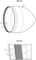
- FIG. 2a represents a view of the assembly of the mixer 20 on the exhaust casing.
- the outer shell of the casing comprises a scalloped flange 15 oriented substantially axially relative to the axis of the turbomachine, the orientation of a flange being defined by the orientation of the bolts allowing its assembly.
- Each scallop comprises a through hole allowing the mixer to be bolted.
- the mixer 20 comprises a scalloped flange 21 corresponding to the flange 15 of the exhaust casing.
- FIG. 2b shows a view of the assembly of the exhaust cone 30 on the exhaust housing 10.
- the inner shell of the housing also includes a substantially radial scalloped flange 16. Each scallop also includes a through hole for bolting the exhaust cone.
- a circumferential section 31 of the exhaust cone includes orifices allowing it to be bolted to the exhaust casing.
- this section includes an excess thickness comprising the radial scalloping in order to drown the heads of the screws and to guarantee the mechanical strength of the connection.
- One of the aims of the invention is to propose an alternative to a bolted connection of an exhaust casing to an exhaust cone, a mixer, or an exhaust nozzle, allowing a saving in the mass of these parts.
- the invention relates to an assembly according to claim 1.
- the invention also relates to a turbomachine, comprising an assembly according to the preceding description.
- the invention may also relate to an exhaust casing, a mixer, an exhaust nozzle or an exhaust cone forming part of the assembly described above.
- the proposed assembly allows a mass reduction of the order of 500 g compared to the prior art. Indeed, the festoons and bolts are removed and replaced by a thread. In the case where the part is an exhaust cone, the excess thickness necessary for bolting the exhaust cone is also removed.
- Threading is a well-suited solution for this type of connection in terms of the mechanical stresses to which the connection is subjected.
- the thread also has the advantage of facilitating the manufacture and maintenance of the assembly, thus reducing its production and maintenance cost.
- the assembly 1 comprises an exhaust casing 110, the exhaust casing being a part of revolution about an axis X-X of the turbomachine.
- the assembly 1 further comprises at least one annular part screwed onto the exhaust casing on a downstream side of the exhaust casing relative to an air flow in the turbomachine - the part being centered on the axis X-X when mounted on the exhaust casing.
- the annular part can be either a nozzle or a mixer 120, in the case where the turbomachine is dual-flow, or an exhaust cone 130.
- the assembly 1 comprises an exhaust casing 110, an exhaust cone 130, as well as a nozzle or mixer 120 screwed onto the casing 110.
- the exhaust casing 110 comprises an internal shell 111 and an external shell 112, these two shells being cylindrical parts of revolution extending one inside the other concentrically around the axis X-X of the turbomachine.
- the exhaust casing further comprises a plurality of radial arms 113 relative to the axis X-X of the turbomachine, extending between the inner shell 111 and the outer shell 112.
- the exhaust casing 110 further comprises at least one circumferential thread, 114, 115, arranged respectively in a surface of the inner ferrule 111 and/or the outer ferrule 112.
- the thread 114, 115 is produced in a radially external surface 111*, 112* of the corresponding ferrule, close to a downstream edge of said surface.
- Each circumferential thread allows the screw mounting of a respective annular part.
- the thread thus extends over a plurality of turns of each ferrule, preferably between 2 and 10 turns, for example over 4, 5 or 6 turns.
- the exhaust casing 110 comprises, on an external surface 112* of the external shell 112, a circumferential thread 114, this thread allowing the mounting by screwing of an exhaust nozzle or a mixer 120 on the external shell 112 of the exhaust casing 110.
- the exhaust casing comprises, on the external surface 111* of the internal ferrule 111, a circumferential thread 115, this thread allowing the mounting by screwing of an exhaust cone 130 on the internal ferrule 111 of the exhaust casing 110.
- the exhaust casing 110 comprises two threads 114, 115 made on the external 112 and internal 111 ferrules, so as to be able to screw a mixer or an exhaust nozzle onto the external ferrule and an exhaust cone onto the internal ferrule.
- the exhaust cone 130 extends inside the exhaust nozzle or mixer 120, in a coaxial manner.
- the scalloped flange previously used for mounting the corresponding downstream part by bolting is removed.
- the annular piece that can be screwed onto the exhaust housing can be a 120 mixer or an exhaust nozzle.
- the latter also comprises a circumferential thread 121.
- the thread 121 is adapted to cooperate with the thread 114 of the outer shell 112 of the exhaust casing 110.
- the circumferential thread of the mixer or nozzle 120 is preferably produced on a radially internal surface 122 thereof, to cooperate with a thread 114 arranged on a radially external surface 112* of the shell 112.
- the annular part which can be screwed onto the exhaust casing can be an exhaust cone 130.
- the latter also comprises a circumferential thread 131.
- the thread 131 is adapted to cooperate with the thread 115 of the inner ferrule of the exhaust casing 110.
- the thread 131 is produced on a radially internal surface 132 of the exhaust cone 130.
- the threads 114, 115 of the exhaust casing 110 as well as the thread(s) 121, 131 of the nozzle/mixer and 120/or of the exhaust cone 130 are adapted to allow good angular indexing of the downstream part 120, 130 relative to the exhaust casing 110.
- the nozzle, the mixer and the exhaust cone may have one or more drainage holes which must be located in the low position when the part is mounted on the casing, i.e. substantially vertically below the axis of the turbomachine (“at 6 o’clock”).
- each thread of the exhaust casing 110 and of the downstream part to be angularly indexed must therefore be adapted to allow this positioning, by precisely choosing the angular position of the start of each thread on each part. To do this, each thread is preferably made by milling.
- the assembly 1 further comprises a system 140 for stopping the downstream part in axial translation on the exhaust casing.
- the stopping system 140 is applicable both to stopping the exhaust cone 130 in translation relative to the casing 110 and to stopping the mixer or nozzle 120 relative to the casing 110.
- the axial translation stop system is shown in the Figure 6a , in the case where the downstream part is an exhaust cone 130, and on the Figure 6b , in the case where it is an exhaust nozzle or a 120 mixer.
- the translation stop system 140 advantageously comprises a groove 141 made adjacent to the thread 114 or 115 of the exhaust casing, that is to say on the external surface respectively of the external ferrule 112 and/or of the internal ferrule 111 of the exhaust casing.
- the groove 141 is preferably circumferential.
- the groove 141 may comprise a plurality of circular sector sections.
- the groove 141 may be replaced by localized machining, arranged at the precise locations of the location of the screws.
- the translation stop system 140 comprises at least one through orifice 142, made in the circumferential wall of the downstream part bearing the thread 131, 132. Each through orifice 142 is threaded.
- each downstream part (mixer or nozzle 120 or exhaust cone 130) comprises a plurality of through orifices 142 arranged regularly on the circumference of the wall carrying the thread.
- the downstream part may comprise three orifices 142 crossings distributed at a constant angular interval of 120°.
- the locations of the orifices 142 are chosen so that the orifices are located opposite the groove 141 of the exhaust casing when the annular part is screwed onto the casing 110.
- the axial translation stop system 140 comprises a plurality of screws 143 adapted to be screwed into the orifices 142. Each screw is thus received in an orifice 142 until it emerges in the groove 141. The end of the screw housed in the groove comes into abutment against the edges of the groove and prevents an axial translation of the downstream part relative to the exhaust casing.
- each screw 143 is shaped so as to be entirely contained in a volume constituted by an orifice 142 of the exhaust cone and the groove 141 of the exhaust casing, so as not to protrude relative to the wall of the exhaust cone 130.
- the head of the screw when the screw is arranged in an orifice, the head of the screw is located at a radially external surface of the exhaust cone.
- the air flow in the turbomachine takes place between the exhaust nozzle/mixer and the exhaust cone, the fact that the head of the screw is projecting relative to the exhaust cone would adversely impact the air flow between the exhaust cone and the mixer or nozzle.
- the screws used can be of the female head type known as BTR or domed head type.
- both the exhaust cone and the nozzle or mixer are shaped so that they can be screwed onto the exhaust housing.
Landscapes
- Engineering & Computer Science (AREA)
- Mechanical Engineering (AREA)
- General Engineering & Computer Science (AREA)
- Chemical & Material Sciences (AREA)
- Combustion & Propulsion (AREA)
- Jet Pumps And Other Pumps (AREA)
- Turbine Rotor Nozzle Sealing (AREA)
- Mixers Of The Rotary Stirring Type (AREA)
- Exhaust Silencers (AREA)
Claims (7)
- Anordnung (1), umfassend:- ein Auslassgehäuse (110) eines Turbinentriebwerks, umfassend zwei Ringe, jeweils einen inneren Ring (111) und einen äußeren Ring (112), die sich, der eine im Inneren des anderen, konzentrisch um eine Achse (X-X) des Turbinentriebwerks erstrecken, und eine Vielzahl von Armen (113), die sich radial zwischen den Ringen erstrecken, und- ein auf der Achse zentriertes ringförmiges Teil (120, 130), das auf einem Ring des Auslassgehäuses (110) in Bezug auf einen Luftstrom in dem Turbinentriebwerk dem Gehäuse nachgelagert angebracht ist,wobei das ringförmige Teil (120, 130) und der Ring (111, 112) des Gehäuses, auf dem es angebracht ist, jeweils ein Umfangsgewinde (121, 131, 114, 115), aufweisen, wobei die Gewinde zusammenwirken, um eine Montage durch Schrauben des ringförmigen Teils auf den Ring des Gehäuses zu gestatten,wobei die Anordnung ferner ein Sperrsystem (140) der axialen Verlagerung des ringförmigen Teils (120, 130) auf dem Ring (111, 112) des Gehäuses (110) umfasst, wobei das Sperrsystem der axialen Verlagerung (140) mindestens eine Nut (141) umfasst, die in dem Ring des Auslassgehäuses in Nachbarschaft zum Gewinde ausgebildet ist, sowie eine Vielzahl gewindeter durchgängiger Öffnungen (142), die auf dem ringförmigen Teil (120, 130) ausgebildet und geeignet sind, sich der Nut (141) zugewandt zu befinden, wenn das Teil auf dem Auslassgehäuse geschraubt ist, und eine Vielzahl von Schrauben (143), die zum Schrauben in den Öffnungen (142) geeignet sind.
- Anordnung nach Anspruch 1, wobei das Gewinde (114, 115) des Rings (111, 112) des Gehäuses auf einer radial äußeren Fläche (111*, 112*) des Rings ausgeführt ist.
- Anordnung nach einem der Ansprüche 1 und 2, wobei die Nut (141) umfänglich ist.
- Anordnung nach einem der vorangehenden Ansprüche, wobei das ringförmige Teil ein Mischer oder eine Auslassdüse (120) ist, der/die auf dem äußeren Ring (112) des Auslassgehäuses (110) angebracht ist.
- Anordnung nach einem der Ansprüche 1 bis 3, wobei das ringförmige Teil ein Austrittskegel (130) ist, der auf dem inneren Ring (111) des Auslassgehäuses (110) angebracht ist.
- Anordnung nach Anspruch 5, wobei jede Schraube (143) ferner ausgebildet ist, um vollständig in einem Volumen enthalten zu sein, das von einer Öffnung (142) des Austrittskegels und der Nut (141) des Auslassgehäuses gebildet ist.
- Turbinentriebwerk, umfassend eine Anordnung (1) nach einem der vorangehenden Ansprüche.
Applications Claiming Priority (2)
| Application Number | Priority Date | Filing Date | Title |
|---|---|---|---|
| FR1555331A FR3037358B1 (fr) | 2015-06-11 | 2015-06-11 | Ensemble a carter d'echappement et piece aval de revolution |
| PCT/FR2016/051415 WO2016198806A1 (fr) | 2015-06-11 | 2016-06-10 | Ensemble a carter d'echappement et piece aval de revolution |
Publications (3)
| Publication Number | Publication Date |
|---|---|
| EP3307991A1 EP3307991A1 (de) | 2018-04-18 |
| EP3307991B1 EP3307991B1 (de) | 2019-05-29 |
| EP3307991B2 true EP3307991B2 (de) | 2024-12-04 |
Family
ID=53776832
Family Applications (1)
| Application Number | Title | Priority Date | Filing Date |
|---|---|---|---|
| EP16735912.4A Active EP3307991B2 (de) | 2015-06-11 | 2016-06-10 | Anordnung mit einem abgasgehäuse und einem nachgeschalteten rotationssymmetrischen teil |
Country Status (5)
| Country | Link |
|---|---|
| US (1) | US11053890B2 (de) |
| EP (1) | EP3307991B2 (de) |
| CN (1) | CN107709744B (de) |
| FR (1) | FR3037358B1 (de) |
| WO (1) | WO2016198806A1 (de) |
Families Citing this family (8)
| Publication number | Priority date | Publication date | Assignee | Title |
|---|---|---|---|---|
| US10330009B2 (en) * | 2017-01-13 | 2019-06-25 | United Technologies Corporation | Lock for threaded in place nosecone or spinner |
| US10612405B2 (en) | 2017-01-13 | 2020-04-07 | United Technologies Corporation | Stator outer platform sealing and retainer |
| US10393065B2 (en) * | 2017-11-09 | 2019-08-27 | United Technologies Corporation | Variable nozzle apparatus |
| US10808613B2 (en) * | 2018-01-09 | 2020-10-20 | Raytheon Technologies Corporation | Assembly for releasable locking of a spinner or nosecone to an engine structure |
| US10774685B2 (en) * | 2018-04-30 | 2020-09-15 | Ratheon Technologies Corporation | Gas turbine engine exhaust component |
| FR3082238A1 (fr) * | 2018-06-11 | 2019-12-13 | Airbus Operations | Tuyere primaire d'un conduit d'ejection primaire d'une turbomachine |
| US11286814B1 (en) * | 2020-09-17 | 2022-03-29 | Pratt & Whitney Canada Corp. | Exhaust duct of gas turbine engine |
| US12410726B1 (en) * | 2024-06-05 | 2025-09-09 | Rtx Corporation | Turbine engine centerbody generator |
Family Cites Families (18)
| Publication number | Priority date | Publication date | Assignee | Title |
|---|---|---|---|---|
| US3014741A (en) * | 1957-12-06 | 1961-12-26 | Gen Motors Corp | Multi-member joint |
| US5480196A (en) * | 1994-08-15 | 1996-01-02 | American Cast Iron Pipe Company | Ductile iron pipe joint employing a coupling and coupling therefor |
| SE511813C2 (sv) * | 1996-10-18 | 1999-11-29 | Atlas Copco Tools Ab | Axialflödesturbin |
| US6908121B2 (en) * | 2001-10-22 | 2005-06-21 | Weatherford/Lamb, Inc. | Locking arrangement for a threaded connector |
| GB0221585D0 (en) * | 2002-09-17 | 2002-10-23 | Weatherford Lamb | Tubing connection arrangement |
| US7384075B2 (en) * | 2004-05-14 | 2008-06-10 | Allison Advanced Development Company | Threaded joint for gas turbine components |
| CN1944996A (zh) * | 2006-04-24 | 2007-04-11 | 江苏江淮动力股份有限公司 | 气体混合器和带有该气体混合器的发动机 |
| FR2978989B1 (fr) * | 2011-08-12 | 2013-07-26 | Aircelle Sa | Cone d'ejection pour turboreacteur d'aeronef |
| US9200537B2 (en) * | 2011-11-09 | 2015-12-01 | Pratt & Whitney Canada Corp. | Gas turbine exhaust case with acoustic panels |
| CA2870754C (en) * | 2012-04-27 | 2017-09-05 | General Electric Company | Connecting gas turbine engine annular members |
| FR2994712B1 (fr) * | 2012-08-27 | 2018-04-13 | Safran Aircraft Engines | Procede d'assemblage d'une tuyere et d'un carter d'echappement d'une turbomachine |
| US20140209291A1 (en) * | 2013-01-28 | 2014-07-31 | Schlumberger Technology Corporation | Seals for electric submersible pump |
| CN203321652U (zh) * | 2013-05-21 | 2013-12-04 | 宁波奥格达汽配有限公司 | 一种易于清理的汽车排气管道 |
| CN204041186U (zh) * | 2014-02-20 | 2014-12-24 | 张立涛 | 一种汽车排气管装饰 |
| US10519805B2 (en) * | 2015-04-13 | 2019-12-31 | United Technologies Corporation | Turbine case coupling |
| US10082042B2 (en) * | 2015-06-22 | 2018-09-25 | United Technologies Corporation | Case coupling and assembly |
| FR3053430B1 (fr) * | 2016-06-30 | 2019-01-25 | Snecma | Ensemble de turbomachine permettant un assemblage etanche d'un cone avant sur une virole avant |
| US10330009B2 (en) * | 2017-01-13 | 2019-06-25 | United Technologies Corporation | Lock for threaded in place nosecone or spinner |
-
2015
- 2015-06-11 FR FR1555331A patent/FR3037358B1/fr active Active
-
2016
- 2016-06-10 EP EP16735912.4A patent/EP3307991B2/de active Active
- 2016-06-10 CN CN201680033063.4A patent/CN107709744B/zh active Active
- 2016-06-10 US US15/580,496 patent/US11053890B2/en active Active
- 2016-06-10 WO PCT/FR2016/051415 patent/WO2016198806A1/fr not_active Ceased
Also Published As
| Publication number | Publication date |
|---|---|
| US20180171932A1 (en) | 2018-06-21 |
| FR3037358A1 (fr) | 2016-12-16 |
| US11053890B2 (en) | 2021-07-06 |
| FR3037358B1 (fr) | 2017-05-19 |
| CN107709744A (zh) | 2018-02-16 |
| EP3307991A1 (de) | 2018-04-18 |
| WO2016198806A1 (fr) | 2016-12-15 |
| EP3307991B1 (de) | 2019-05-29 |
| CN107709744B (zh) | 2019-09-20 |
Similar Documents
| Publication | Publication Date | Title |
|---|---|---|
| EP3307991B2 (de) | Anordnung mit einem abgasgehäuse und einem nachgeschalteten rotationssymmetrischen teil | |
| EP3074609B1 (de) | Vorrichtung zur führung von synchronringschaufeln mit verstellbarem neigungswinkel eines turbinenmotors und verfahren zur montage solch einer vorrichtung | |
| EP3234311B1 (de) | System zur reparatur einer befestigung einer reaktorwand | |
| EP3074639B1 (de) | Gebläse, insbesondere für eine turbomaschine, sowie flansch dafür | |
| CA2913579A1 (fr) | Carter de turbomachine comportant un orifice d'endoscopie | |
| FR2935429A1 (fr) | Aubage fixe de turbomachine a masse reduite et turbomachine comportant au moins un tel aubage fixe | |
| FR3016936A1 (fr) | Disque de rotor a dispositif de prelevement d'air centripete, compresseur comportant ledit disque et turbomachine avec un tel compresseur | |
| FR3009335A1 (fr) | Dispositif de guidage d'aubes de redresseur a angle de calage variable de turbomachine | |
| EP3201531B1 (de) | Brennkammer einer turbomaschine | |
| WO2019162146A1 (fr) | Dispositif de retenue pour organe filete, notamment pour ecrou | |
| FR3046951A1 (fr) | Procede de fabrication d'une piece d'une turbomachine et piece ainsi realisee | |
| CA2602938C (fr) | Chambre de combustion annulaire d'une turbomachine | |
| EP4010563B1 (de) | Prallkühlvorrichtung für ein turbomaschinen-aussengehäuse und turbomaschine mit entsprechender vorrichtung | |
| EP3824221B1 (de) | Anordnung für eine turbomaschine | |
| FR3041381A1 (fr) | Ensemble a carter d'echappement et element aval monte par baionnette | |
| EP4034752B1 (de) | Anordnung für einen turbinenmotor | |
| FR3082228A1 (fr) | Piece de turbomachine comprenant une rondelle cooperant avec un lamage | |
| FR3081187A1 (fr) | Coupelle de protection d'un lamage a montage sans interference | |
| FR3042825A1 (fr) | Aube et disque de soufflante | |
| EP3969814B1 (de) | Gasturbinenmaschine mit brennkammerbefestigung | |
| FR3054801A1 (fr) | Dispositif d'extraction d'au moins une piece d'un module d'une turbomachine, module et turbomachine munis d'un tel dispositif | |
| WO2025022074A1 (fr) | Systeme de blocage d'un bouchon dans une piece de turbomachine d'aeronef, de preference un arbre de turbomachine | |
| FR3150550A1 (fr) | Dispositif d’accouplement de deux pièces de turbomachine d’aéronef | |
| WO2025022073A1 (fr) | Systeme d'accouplement de deux pieces de turbomachine d'aeronef, de preference deux arbres de turbomachine | |
| FR3162478A1 (fr) | Dispositif de fixation de modules de turbomachine |
Legal Events
| Date | Code | Title | Description |
|---|---|---|---|
| STAA | Information on the status of an ep patent application or granted ep patent |
Free format text: STATUS: THE INTERNATIONAL PUBLICATION HAS BEEN MADE |
|
| PUAI | Public reference made under article 153(3) epc to a published international application that has entered the european phase |
Free format text: ORIGINAL CODE: 0009012 |
|
| STAA | Information on the status of an ep patent application or granted ep patent |
Free format text: STATUS: REQUEST FOR EXAMINATION WAS MADE |
|
| 17P | Request for examination filed |
Effective date: 20180111 |
|
| AK | Designated contracting states |
Kind code of ref document: A1 Designated state(s): AL AT BE BG CH CY CZ DE DK EE ES FI FR GB GR HR HU IE IS IT LI LT LU LV MC MK MT NL NO PL PT RO RS SE SI SK SM TR |
|
| AX | Request for extension of the european patent |
Extension state: BA ME |
|
| DAV | Request for validation of the european patent (deleted) | ||
| DAX | Request for extension of the european patent (deleted) | ||
| GRAP | Despatch of communication of intention to grant a patent |
Free format text: ORIGINAL CODE: EPIDOSNIGR1 |
|
| STAA | Information on the status of an ep patent application or granted ep patent |
Free format text: STATUS: GRANT OF PATENT IS INTENDED |
|
| INTG | Intention to grant announced |
Effective date: 20190107 |
|
| GRAS | Grant fee paid |
Free format text: ORIGINAL CODE: EPIDOSNIGR3 |
|
| GRAA | (expected) grant |
Free format text: ORIGINAL CODE: 0009210 |
|
| STAA | Information on the status of an ep patent application or granted ep patent |
Free format text: STATUS: THE PATENT HAS BEEN GRANTED |
|
| AK | Designated contracting states |
Kind code of ref document: B1 Designated state(s): AL AT BE BG CH CY CZ DE DK EE ES FI FR GB GR HR HU IE IS IT LI LT LU LV MC MK MT NL NO PL PT RO RS SE SI SK SM TR |
|
| REG | Reference to a national code |
Ref country code: GB Ref legal event code: FG4D Free format text: NOT ENGLISH |
|
| REG | Reference to a national code |
Ref country code: CH Ref legal event code: EP |
|
| REG | Reference to a national code |
Ref country code: AT Ref legal event code: REF Ref document number: 1138385 Country of ref document: AT Kind code of ref document: T Effective date: 20190615 |
|
| REG | Reference to a national code |
Ref country code: DE Ref legal event code: R096 Ref document number: 602016014590 Country of ref document: DE |
|
| REG | Reference to a national code |
Ref country code: IE Ref legal event code: FG4D Free format text: LANGUAGE OF EP DOCUMENT: FRENCH |
|
| REG | Reference to a national code |
Ref country code: SE Ref legal event code: TRGR |
|
| REG | Reference to a national code |
Ref country code: NL Ref legal event code: MP Effective date: 20190529 |
|
| REG | Reference to a national code |
Ref country code: LT Ref legal event code: MG4D |
|
| PG25 | Lapsed in a contracting state [announced via postgrant information from national office to epo] |
Ref country code: PT Free format text: LAPSE BECAUSE OF FAILURE TO SUBMIT A TRANSLATION OF THE DESCRIPTION OR TO PAY THE FEE WITHIN THE PRESCRIBED TIME-LIMIT Effective date: 20190930 Ref country code: ES Free format text: LAPSE BECAUSE OF FAILURE TO SUBMIT A TRANSLATION OF THE DESCRIPTION OR TO PAY THE FEE WITHIN THE PRESCRIBED TIME-LIMIT Effective date: 20190529 Ref country code: LT Free format text: LAPSE BECAUSE OF FAILURE TO SUBMIT A TRANSLATION OF THE DESCRIPTION OR TO PAY THE FEE WITHIN THE PRESCRIBED TIME-LIMIT Effective date: 20190529 Ref country code: FI Free format text: LAPSE BECAUSE OF FAILURE TO SUBMIT A TRANSLATION OF THE DESCRIPTION OR TO PAY THE FEE WITHIN THE PRESCRIBED TIME-LIMIT Effective date: 20190529 Ref country code: HR Free format text: LAPSE BECAUSE OF FAILURE TO SUBMIT A TRANSLATION OF THE DESCRIPTION OR TO PAY THE FEE WITHIN THE PRESCRIBED TIME-LIMIT Effective date: 20190529 Ref country code: AL Free format text: LAPSE BECAUSE OF FAILURE TO SUBMIT A TRANSLATION OF THE DESCRIPTION OR TO PAY THE FEE WITHIN THE PRESCRIBED TIME-LIMIT Effective date: 20190529 Ref country code: NO Free format text: LAPSE BECAUSE OF FAILURE TO SUBMIT A TRANSLATION OF THE DESCRIPTION OR TO PAY THE FEE WITHIN THE PRESCRIBED TIME-LIMIT Effective date: 20190829 |
|
| PG25 | Lapsed in a contracting state [announced via postgrant information from national office to epo] |
Ref country code: GR Free format text: LAPSE BECAUSE OF FAILURE TO SUBMIT A TRANSLATION OF THE DESCRIPTION OR TO PAY THE FEE WITHIN THE PRESCRIBED TIME-LIMIT Effective date: 20190830 Ref country code: LV Free format text: LAPSE BECAUSE OF FAILURE TO SUBMIT A TRANSLATION OF THE DESCRIPTION OR TO PAY THE FEE WITHIN THE PRESCRIBED TIME-LIMIT Effective date: 20190529 Ref country code: RS Free format text: LAPSE BECAUSE OF FAILURE TO SUBMIT A TRANSLATION OF THE DESCRIPTION OR TO PAY THE FEE WITHIN THE PRESCRIBED TIME-LIMIT Effective date: 20190529 Ref country code: BG Free format text: LAPSE BECAUSE OF FAILURE TO SUBMIT A TRANSLATION OF THE DESCRIPTION OR TO PAY THE FEE WITHIN THE PRESCRIBED TIME-LIMIT Effective date: 20190829 |
|
| REG | Reference to a national code |
Ref country code: AT Ref legal event code: MK05 Ref document number: 1138385 Country of ref document: AT Kind code of ref document: T Effective date: 20190529 |
|
| PG25 | Lapsed in a contracting state [announced via postgrant information from national office to epo] |
Ref country code: AT Free format text: LAPSE BECAUSE OF FAILURE TO SUBMIT A TRANSLATION OF THE DESCRIPTION OR TO PAY THE FEE WITHIN THE PRESCRIBED TIME-LIMIT Effective date: 20190529 Ref country code: DK Free format text: LAPSE BECAUSE OF FAILURE TO SUBMIT A TRANSLATION OF THE DESCRIPTION OR TO PAY THE FEE WITHIN THE PRESCRIBED TIME-LIMIT Effective date: 20190529 Ref country code: NL Free format text: LAPSE BECAUSE OF FAILURE TO SUBMIT A TRANSLATION OF THE DESCRIPTION OR TO PAY THE FEE WITHIN THE PRESCRIBED TIME-LIMIT Effective date: 20190529 Ref country code: EE Free format text: LAPSE BECAUSE OF FAILURE TO SUBMIT A TRANSLATION OF THE DESCRIPTION OR TO PAY THE FEE WITHIN THE PRESCRIBED TIME-LIMIT Effective date: 20190529 Ref country code: CZ Free format text: LAPSE BECAUSE OF FAILURE TO SUBMIT A TRANSLATION OF THE DESCRIPTION OR TO PAY THE FEE WITHIN THE PRESCRIBED TIME-LIMIT Effective date: 20190529 Ref country code: RO Free format text: LAPSE BECAUSE OF FAILURE TO SUBMIT A TRANSLATION OF THE DESCRIPTION OR TO PAY THE FEE WITHIN THE PRESCRIBED TIME-LIMIT Effective date: 20190529 Ref country code: SK Free format text: LAPSE BECAUSE OF FAILURE TO SUBMIT A TRANSLATION OF THE DESCRIPTION OR TO PAY THE FEE WITHIN THE PRESCRIBED TIME-LIMIT Effective date: 20190529 |
|
| REG | Reference to a national code |
Ref country code: CH Ref legal event code: PL |
|
| PG25 | Lapsed in a contracting state [announced via postgrant information from national office to epo] |
Ref country code: SM Free format text: LAPSE BECAUSE OF FAILURE TO SUBMIT A TRANSLATION OF THE DESCRIPTION OR TO PAY THE FEE WITHIN THE PRESCRIBED TIME-LIMIT Effective date: 20190529 Ref country code: MC Free format text: LAPSE BECAUSE OF FAILURE TO SUBMIT A TRANSLATION OF THE DESCRIPTION OR TO PAY THE FEE WITHIN THE PRESCRIBED TIME-LIMIT Effective date: 20190529 |
|
| REG | Reference to a national code |
Ref country code: DE Ref legal event code: R026 Ref document number: 602016014590 Country of ref document: DE |
|
| PLBI | Opposition filed |
Free format text: ORIGINAL CODE: 0009260 |
|
| PLAX | Notice of opposition and request to file observation + time limit sent |
Free format text: ORIGINAL CODE: EPIDOSNOBS2 |
|
| REG | Reference to a national code |
Ref country code: BE Ref legal event code: MM Effective date: 20190630 |
|
| PG25 | Lapsed in a contracting state [announced via postgrant information from national office to epo] |
Ref country code: TR Free format text: LAPSE BECAUSE OF FAILURE TO SUBMIT A TRANSLATION OF THE DESCRIPTION OR TO PAY THE FEE WITHIN THE PRESCRIBED TIME-LIMIT Effective date: 20190529 |
|
| 26 | Opposition filed |
Opponent name: UNITED TECHNOLOGIES CORPORATION Effective date: 20200302 |
|
| PG25 | Lapsed in a contracting state [announced via postgrant information from national office to epo] |
Ref country code: IE Free format text: LAPSE BECAUSE OF NON-PAYMENT OF DUE FEES Effective date: 20190610 Ref country code: PL Free format text: LAPSE BECAUSE OF FAILURE TO SUBMIT A TRANSLATION OF THE DESCRIPTION OR TO PAY THE FEE WITHIN THE PRESCRIBED TIME-LIMIT Effective date: 20190529 |
|
| PG25 | Lapsed in a contracting state [announced via postgrant information from national office to epo] |
Ref country code: CH Free format text: LAPSE BECAUSE OF NON-PAYMENT OF DUE FEES Effective date: 20190630 Ref country code: LU Free format text: LAPSE BECAUSE OF NON-PAYMENT OF DUE FEES Effective date: 20190610 Ref country code: LI Free format text: LAPSE BECAUSE OF NON-PAYMENT OF DUE FEES Effective date: 20190630 Ref country code: SI Free format text: LAPSE BECAUSE OF FAILURE TO SUBMIT A TRANSLATION OF THE DESCRIPTION OR TO PAY THE FEE WITHIN THE PRESCRIBED TIME-LIMIT Effective date: 20190529 Ref country code: BE Free format text: LAPSE BECAUSE OF NON-PAYMENT OF DUE FEES Effective date: 20190630 |
|
| PLBB | Reply of patent proprietor to notice(s) of opposition received |
Free format text: ORIGINAL CODE: EPIDOSNOBS3 |
|
| PLAB | Opposition data, opponent's data or that of the opponent's representative modified |
Free format text: ORIGINAL CODE: 0009299OPPO |
|
| R26 | Opposition filed (corrected) |
Opponent name: RAYTHEON TECHNOLOGIES CORPORATION Effective date: 20200302 |
|
| PG25 | Lapsed in a contracting state [announced via postgrant information from national office to epo] |
Ref country code: CY Free format text: LAPSE BECAUSE OF FAILURE TO SUBMIT A TRANSLATION OF THE DESCRIPTION OR TO PAY THE FEE WITHIN THE PRESCRIBED TIME-LIMIT Effective date: 20190529 |
|
| PG25 | Lapsed in a contracting state [announced via postgrant information from national office to epo] |
Ref country code: IS Free format text: LAPSE BECAUSE OF FAILURE TO SUBMIT A TRANSLATION OF THE DESCRIPTION OR TO PAY THE FEE WITHIN THE PRESCRIBED TIME-LIMIT Effective date: 20190929 |
|
| PG25 | Lapsed in a contracting state [announced via postgrant information from national office to epo] |
Ref country code: HU Free format text: LAPSE BECAUSE OF FAILURE TO SUBMIT A TRANSLATION OF THE DESCRIPTION OR TO PAY THE FEE WITHIN THE PRESCRIBED TIME-LIMIT; INVALID AB INITIO Effective date: 20160610 Ref country code: MT Free format text: LAPSE BECAUSE OF FAILURE TO SUBMIT A TRANSLATION OF THE DESCRIPTION OR TO PAY THE FEE WITHIN THE PRESCRIBED TIME-LIMIT Effective date: 20190529 |
|
| APBM | Appeal reference recorded |
Free format text: ORIGINAL CODE: EPIDOSNREFNO |
|
| APBP | Date of receipt of notice of appeal recorded |
Free format text: ORIGINAL CODE: EPIDOSNNOA2O |
|
| APAH | Appeal reference modified |
Free format text: ORIGINAL CODE: EPIDOSCREFNO |
|
| APAW | Appeal reference deleted |
Free format text: ORIGINAL CODE: EPIDOSDREFNO |
|
| APBQ | Date of receipt of statement of grounds of appeal recorded |
Free format text: ORIGINAL CODE: EPIDOSNNOA3O |
|
| APBQ | Date of receipt of statement of grounds of appeal recorded |
Free format text: ORIGINAL CODE: EPIDOSNNOA3O |
|
| PG25 | Lapsed in a contracting state [announced via postgrant information from national office to epo] |
Ref country code: MK Free format text: LAPSE BECAUSE OF FAILURE TO SUBMIT A TRANSLATION OF THE DESCRIPTION OR TO PAY THE FEE WITHIN THE PRESCRIBED TIME-LIMIT Effective date: 20190529 |
|
| APAH | Appeal reference modified |
Free format text: ORIGINAL CODE: EPIDOSCREFNO |
|
| APBU | Appeal procedure closed |
Free format text: ORIGINAL CODE: EPIDOSNNOA9O |
|
| PUAH | Patent maintained in amended form |
Free format text: ORIGINAL CODE: 0009272 |
|
| STAA | Information on the status of an ep patent application or granted ep patent |
Free format text: STATUS: PATENT MAINTAINED AS AMENDED |
|
| 27A | Patent maintained in amended form |
Effective date: 20241204 |
|
| AK | Designated contracting states |
Kind code of ref document: B2 Designated state(s): AL AT BE BG CH CY CZ DE DK EE ES FI FR GB GR HR HU IE IS IT LI LT LU LV MC MK MT NL NO PL PT RO RS SE SI SK SM TR |
|
| REG | Reference to a national code |
Ref country code: DE Ref legal event code: R102 Ref document number: 602016014590 Country of ref document: DE |
|
| REG | Reference to a national code |
Ref country code: SE Ref legal event code: RPEO |
|
| PGFP | Annual fee paid to national office [announced via postgrant information from national office to epo] |
Ref country code: DE Payment date: 20250618 Year of fee payment: 10 |
|
| PGFP | Annual fee paid to national office [announced via postgrant information from national office to epo] |
Ref country code: GB Payment date: 20250625 Year of fee payment: 10 |
|
| PGFP | Annual fee paid to national office [announced via postgrant information from national office to epo] |
Ref country code: FR Payment date: 20250623 Year of fee payment: 10 |
|
| PGFP | Annual fee paid to national office [announced via postgrant information from national office to epo] |
Ref country code: SE Payment date: 20250618 Year of fee payment: 10 |
|
| PGFP | Annual fee paid to national office [announced via postgrant information from national office to epo] |
Ref country code: IT Payment date: 20250630 Year of fee payment: 10 |