EP3307663B1 - Self-adjusting reel assembly apparatus, system and method - Google Patents
Self-adjusting reel assembly apparatus, system and method Download PDFInfo
- Publication number
- EP3307663B1 EP3307663B1 EP16807934.1A EP16807934A EP3307663B1 EP 3307663 B1 EP3307663 B1 EP 3307663B1 EP 16807934 A EP16807934 A EP 16807934A EP 3307663 B1 EP3307663 B1 EP 3307663B1
- Authority
- EP
- European Patent Office
- Prior art keywords
- spool
- umbilical
- accelerometer
- pressure
- reel
- Prior art date
- Legal status (The legal status is an assumption and is not a legal conclusion. Google has not performed a legal analysis and makes no representation as to the accuracy of the status listed.)
- Active
Links
- 238000000034 method Methods 0.000 title description 20
- 238000012545 processing Methods 0.000 claims description 17
- 238000004891 communication Methods 0.000 claims description 6
- 238000005553 drilling Methods 0.000 description 25
- 230000008569 process Effects 0.000 description 12
- 239000012530 fluid Substances 0.000 description 6
- 238000010276 construction Methods 0.000 description 5
- 230000001276 controlling effect Effects 0.000 description 5
- 230000008901 benefit Effects 0.000 description 4
- 239000000835 fiber Substances 0.000 description 4
- 238000004590 computer program Methods 0.000 description 3
- 238000004880 explosion Methods 0.000 description 3
- 230000001105 regulatory effect Effects 0.000 description 3
- 230000015572 biosynthetic process Effects 0.000 description 2
- 230000008859 change Effects 0.000 description 2
- 238000005755 formation reaction Methods 0.000 description 2
- 239000000463 material Substances 0.000 description 2
- 240000005561 Musa balbisiana Species 0.000 description 1
- 235000018290 Musa x paradisiaca Nutrition 0.000 description 1
- 239000000654 additive Substances 0.000 description 1
- 230000000996 additive effect Effects 0.000 description 1
- 238000004364 calculation method Methods 0.000 description 1
- 238000013461 design Methods 0.000 description 1
- 230000009977 dual effect Effects 0.000 description 1
- 230000000694 effects Effects 0.000 description 1
- 238000005188 flotation Methods 0.000 description 1
- 230000006870 function Effects 0.000 description 1
- 230000008571 general function Effects 0.000 description 1
- 231100001261 hazardous Toxicity 0.000 description 1
- 238000009434 installation Methods 0.000 description 1
- 238000004519 manufacturing process Methods 0.000 description 1
- 238000012544 monitoring process Methods 0.000 description 1
- 210000002445 nipple Anatomy 0.000 description 1
- 238000004382 potting Methods 0.000 description 1
- 230000001012 protector Effects 0.000 description 1
- 238000005086 pumping Methods 0.000 description 1
- 230000008929 regeneration Effects 0.000 description 1
- 238000011069 regeneration method Methods 0.000 description 1
- 230000003252 repetitive effect Effects 0.000 description 1
- 239000007787 solid Substances 0.000 description 1
- XLYOFNOQVPJJNP-UHFFFAOYSA-N water Substances O XLYOFNOQVPJJNP-UHFFFAOYSA-N 0.000 description 1
Images


Classifications
-
- E—FIXED CONSTRUCTIONS
- E21—EARTH OR ROCK DRILLING; MINING
- E21B—EARTH OR ROCK DRILLING; OBTAINING OIL, GAS, WATER, SOLUBLE OR MELTABLE MATERIALS OR A SLURRY OF MINERALS FROM WELLS
- E21B19/00—Handling rods, casings, tubes or the like outside the borehole, e.g. in the derrick; Apparatus for feeding the rods or cables
- E21B19/002—Handling rods, casings, tubes or the like outside the borehole, e.g. in the derrick; Apparatus for feeding the rods or cables specially adapted for underwater drilling
- E21B19/004—Handling rods, casings, tubes or the like outside the borehole, e.g. in the derrick; Apparatus for feeding the rods or cables specially adapted for underwater drilling supporting a riser from a drilling or production platform
- E21B19/006—Handling rods, casings, tubes or the like outside the borehole, e.g. in the derrick; Apparatus for feeding the rods or cables specially adapted for underwater drilling supporting a riser from a drilling or production platform including heave compensators
-
- E—FIXED CONSTRUCTIONS
- E21—EARTH OR ROCK DRILLING; MINING
- E21B—EARTH OR ROCK DRILLING; OBTAINING OIL, GAS, WATER, SOLUBLE OR MELTABLE MATERIALS OR A SLURRY OF MINERALS FROM WELLS
- E21B19/00—Handling rods, casings, tubes or the like outside the borehole, e.g. in the derrick; Apparatus for feeding the rods or cables
- E21B19/008—Winding units, specially adapted for drilling operations
-
- E—FIXED CONSTRUCTIONS
- E21—EARTH OR ROCK DRILLING; MINING
- E21B—EARTH OR ROCK DRILLING; OBTAINING OIL, GAS, WATER, SOLUBLE OR MELTABLE MATERIALS OR A SLURRY OF MINERALS FROM WELLS
- E21B17/00—Drilling rods or pipes; Flexible drill strings; Kellies; Drill collars; Sucker rods; Cables; Casings; Tubings
- E21B17/01—Risers
-
- E—FIXED CONSTRUCTIONS
- E21—EARTH OR ROCK DRILLING; MINING
- E21B—EARTH OR ROCK DRILLING; OBTAINING OIL, GAS, WATER, SOLUBLE OR MELTABLE MATERIALS OR A SLURRY OF MINERALS FROM WELLS
- E21B19/00—Handling rods, casings, tubes or the like outside the borehole, e.g. in the derrick; Apparatus for feeding the rods or cables
- E21B19/002—Handling rods, casings, tubes or the like outside the borehole, e.g. in the derrick; Apparatus for feeding the rods or cables specially adapted for underwater drilling
-
- E—FIXED CONSTRUCTIONS
- E21—EARTH OR ROCK DRILLING; MINING
- E21B—EARTH OR ROCK DRILLING; OBTAINING OIL, GAS, WATER, SOLUBLE OR MELTABLE MATERIALS OR A SLURRY OF MINERALS FROM WELLS
- E21B19/00—Handling rods, casings, tubes or the like outside the borehole, e.g. in the derrick; Apparatus for feeding the rods or cables
- E21B19/02—Rod or cable suspensions
-
- E—FIXED CONSTRUCTIONS
- E21—EARTH OR ROCK DRILLING; MINING
- E21B—EARTH OR ROCK DRILLING; OBTAINING OIL, GAS, WATER, SOLUBLE OR MELTABLE MATERIALS OR A SLURRY OF MINERALS FROM WELLS
- E21B19/00—Handling rods, casings, tubes or the like outside the borehole, e.g. in the derrick; Apparatus for feeding the rods or cables
- E21B19/22—Handling reeled pipe or rod units, e.g. flexible drilling pipes
-
- F—MECHANICAL ENGINEERING; LIGHTING; HEATING; WEAPONS; BLASTING
- F16—ENGINEERING ELEMENTS AND UNITS; GENERAL MEASURES FOR PRODUCING AND MAINTAINING EFFECTIVE FUNCTIONING OF MACHINES OR INSTALLATIONS; THERMAL INSULATION IN GENERAL
- F16D—COUPLINGS FOR TRANSMITTING ROTATION; CLUTCHES; BRAKES
- F16D65/00—Parts or details
- F16D65/02—Braking members; Mounting thereof
- F16D65/04—Bands, shoes or pads; Pivots or supporting members therefor
- F16D65/092—Bands, shoes or pads; Pivots or supporting members therefor for axially-engaging brakes, e.g. disc brakes
-
- G—PHYSICS
- G01—MEASURING; TESTING
- G01P—MEASURING LINEAR OR ANGULAR SPEED, ACCELERATION, DECELERATION, OR SHOCK; INDICATING PRESENCE, ABSENCE, OR DIRECTION, OF MOVEMENT
- G01P13/00—Indicating or recording presence, absence, or direction, of movement
- G01P13/02—Indicating direction only, e.g. by weather vane
-
- G—PHYSICS
- G05—CONTROLLING; REGULATING
- G05B—CONTROL OR REGULATING SYSTEMS IN GENERAL; FUNCTIONAL ELEMENTS OF SUCH SYSTEMS; MONITORING OR TESTING ARRANGEMENTS FOR SUCH SYSTEMS OR ELEMENTS
- G05B15/00—Systems controlled by a computer
- G05B15/02—Systems controlled by a computer electric
-
- F—MECHANICAL ENGINEERING; LIGHTING; HEATING; WEAPONS; BLASTING
- F16—ENGINEERING ELEMENTS AND UNITS; GENERAL MEASURES FOR PRODUCING AND MAINTAINING EFFECTIVE FUNCTIONING OF MACHINES OR INSTALLATIONS; THERMAL INSULATION IN GENERAL
- F16D—COUPLINGS FOR TRANSMITTING ROTATION; CLUTCHES; BRAKES
- F16D7/00—Slip couplings, e.g. slipping on overload, for absorbing shock
- F16D7/02—Slip couplings, e.g. slipping on overload, for absorbing shock of the friction type
Definitions
- the present application provides an apparatus for automatically maintaining a relatively constant tension and a relatively constant slippage load on an umbilical which is deployed from a spool on a reel by being clamped to a subsea drilling riser.
- the invention provides a reel assembly for an offshore umbilical comprising a frame having an axle; a spool having flanges and a drum wherein said spool is mounted on said axle and adapted to hold said offshore umbilical; a motor in communication with said spool and adapted to rotate said spool; a tensioning device adapted to automatically maintain a relatively constant tension and a relatively constant slippage load on said umbilical when deployed from said spool wherein said tensioning device comprises a primary accelerometer attached to said spool and a secondary accelerometer which is attached to said spool at an angle from the primary accelerometer wherein the primary accelerometer and the secondary accelerometer are arranged to detect rotational direction of said spool; and a processing computer in communication with the primary accelerometer, the secondary accelerometer and
- slip clutches 116A, 116B and 116C are seen, with the fourth slip clutch 116D being hidden behind control box or panel 126.
- spool control module 132 will see four indications, so will divide the number by 4 to get the actual number of rotations.
- Access covers 134 and 136 are shown on the end of spool 110. These give access to the inside of the spool 110 to install and service spool control module 132.
- sensing component 232 If sensing component 232 is sensing when sensing component 230 starts sensing protrusion 224, it will mean that the reel is rotating in the take-up direction. If sensing component 232 is not sensing when sensing component 230 starts sensing protrusion 224, it will mean that the reel is rotating in the payout direction.
- Processing computer 240 is initially set up with inputs on the spool drum diameter, spool width, spool flange diameter, umbilical diameter, the starting dimension from the outer diameter of the spool flange, and the distance from the side of the spool flange to the current umbilical position.
- the processing computer 240 receives the indications from sensing components 230 and 232, calculates the current wrap of the umbilical on the spool, and determines the appropriate motor air pressure to provide the appropriate torque and the appropriate slip clutch air pressure for port 176 of Fig. 7 to set the appropriate slippage setting.
- the general goal of these calculations is to end up with a constant tension pull on the umbilical, e.g.
- Box 314 is also shown to be located inside spool 110 as shown in box 310 rather than on the frame as box 312 and box 204 are. Whereas box 204 provided a single processing computer 240 to control both the motor pressure and the slip clutch pressure, in this configuration box 312 controls the motor pressure and box 314 controls the slip clutch pressure.
- box 312 controls the motor pressure
- box 314 controls the slip clutch pressure.
- One effect of this is that the signal is going through the swivel in the opposite direction, and another is that you no longer need a swivel if you make battery pack 315 within box 314 large enough to run several trips to the seafloor or sufficient air supply can be supplied in air tank 316 through connector 317 or air swivel 210 to power air motor 318, which drives generator 319 to keep the battery pack 315 charged.
Landscapes
- Engineering & Computer Science (AREA)
- Geology (AREA)
- Life Sciences & Earth Sciences (AREA)
- Mining & Mineral Resources (AREA)
- Physics & Mathematics (AREA)
- Mechanical Engineering (AREA)
- Environmental & Geological Engineering (AREA)
- Fluid Mechanics (AREA)
- General Life Sciences & Earth Sciences (AREA)
- Geochemistry & Mineralogy (AREA)
- General Engineering & Computer Science (AREA)
- General Physics & Mathematics (AREA)
- Automation & Control Theory (AREA)
- Earth Drilling (AREA)
Description
- In general, the present invention relates to an apparatus, system and method for a self-adjusting computer controlled reel assembly. More particularly, the present invention provides a new and improved reel assembly that may maintain a constant tension and constant slippage setting on the umbilical of an offshore reel as the radius to the umbilical varies and the deployment direction is reversed.
- When subsea blowout preventer stacks are lowered to the seafloor to facilitate the drilling of oil and gas wells, they are lowered on a drilling riser, which has a long conduit with an inner diameter typically about nineteen inches, which acts as the main conduit for the drilling operations. On the outside of this conduit will be flotation material to make it lighter in water, high pressure circulation lines called choke and kill lines, and control umbilicals. The control umbilicals can be hydraulic, electrical, fiber optic, or a combination of these.
- The umbilicals are clamped to the high pressure lines on the riser such that the drilling riser carries the weight of the deployed lines. The umbilicals are handled at the surface by reels, which must payout the umbilical when the drilling riser is lowered and rewind the umbilical when the drilling riser is retrieved. Umbilicals may be hoses, wire rope, cable, hoses, fiber optics, electrical, or combinations of these.
- A first level of control of these reels was to have a valve controlling a motor on the reels and simply keep up with the movement of the drilling riser. This was made practical with a "service loop" which sent the umbilicals over a first sheave, down a loose loop, back up over a second sheave, and then clamped to the riser.
- A next level of control was to simply use an air throttle and put the umbilical in tension at all times. When the drilling riser is lowered, it pulls the motor against the pneumatic supply and pumps air back into the air system, somewhat like regeneration, or dumped the generated air across a relief valve. Dumping the generated air is more workable as the pneumatic supply is likely of too high a pressure to pump back into. As the radius to the umbilical being deployed from a full spool to an empty spool can vary by as much as 3/1, an umbilical tension of 454.6 kg (1,000 lbs.) at the outer wrap will translate into 1361 kg (3,000 lbs.) at the inner wrap. This means that you must have personnel monitoring the reel to keep the tension down with a reasonable range. Furthermore, you have a slip clutch to prevent high tension if a drilling riser is lowered when the brakes are set on the reel; a slip clutch setting of 680.4 kg (1,500 lbs.) at the outer wrap becomes a slip clutch setting of 2041 kg (4,500 lbs.) at the inner wrap.
- What this means is that in all these cases, personnel must be committed to monitor and control the umbilical tension at all times during the running operations. This added head count in a space constrained expensive offshore rig is required at the critical time when the blowout preventer stack and drilling riser is run and personnel commitment is at the maximum.
- Even with the added personnel commitment to monitor and control the umbilical tension, no solution has been available for this high safety slippage setting when the umbilical is being paid off from the inner wraps. With the long studies of trying to reduce personnel requirements on these offshore rigs, there has been no solution offered for these problems.
- Prior art attempts at improvements to this problem have obviously not provided the desired solutions. Thus, there is a need for an apparatus, process and or system that provides a self-adjusting intelligent reel assembly for reels. The above discussed limitations in the prior art is not exhaustive. The current invention provides an inexpensive, time saving, more reliable apparatus, method and system for reels where the prior art fails.
-
US2011006150A1 discloses a method comprising providing a main disk, mounting the main disk on the spool of the reel with a slip connection which will be automatically controlled and connecting motor power for the reel to the main disk, connecting brakes to the main disk. - In view of the foregoing disadvantages inherent in the known types of reels utilized with offshore applications now present in the prior art, the present invention provides a new and improved reel apparatus. As such, the general purpose of the present invention, which will be described subsequently in greater detail, is to provide a new and improved reel, which has all the advantages of the prior art devices and none and or fewer of the disadvantages.
- The present application provides an apparatus for automatically maintaining a relatively constant tension and a relatively constant slippage load on an umbilical which is deployed from a spool on a reel by being clamped to a subsea drilling riser. The invention provides a reel assembly for an offshore umbilical comprising a frame having an axle; a spool having flanges and a drum wherein said spool is mounted on said axle and adapted to hold said offshore umbilical; a motor in communication with said spool and adapted to rotate said spool; a tensioning device adapted to automatically maintain a relatively constant tension and a relatively constant slippage load on said umbilical when deployed from said spool wherein said tensioning device comprises a primary accelerometer attached to said spool and a secondary accelerometer which is attached to said spool at an angle from the primary accelerometer wherein the primary accelerometer and the secondary accelerometer are arranged to detect rotational direction of said spool; and a processing computer in communication with the primary accelerometer, the secondary accelerometer and the motor wherein the processing computer is adapted to compute the relative constant tension and the relative constant slippage and control the motor based on g force readings of the primary accelerometer and the secondary accelerometer.
- There has thus been outlined, rather broadly, the more important features of the invention in order that the detailed description thereof that follows may be better understood and in order that the present contribution to the art may be better appreciated. There are, of course, additional features of the invention that will be described hereinafter and which will form the subject matter of the claims appended hereto.
- In this respect, before explaining at least one embodiment of the invention in detail, it is to be understood that the invention is not limited in this application to the details of construction and to the arrangements of the components set forth in the following description or illustrated in the drawings. The invention is capable of other embodiments and of being practiced and carried out in various ways. Also, it is to be understood that the phraseology and terminology employed herein are for the purpose of description and should not be regarded as limiting. As such, those skilled in the art will appreciate that the conception upon which this disclosure is based may readily be utilized as a basis for the designing of other structures, methods and systems for carrying out the several purposes of the present invention. It is important, therefore, that the claims be regarded as including such equivalent constructions insofar as they do not depart from the scope of the present invention as defined in the appended claims.
- Therefore, it is an object of the present invention to provide a new and improved reel apparatus that may provide an automatically controlling of the tension of a deepwater umbilical as a blowout preventer stack is lowered on a drilling riser and the radius to the umbilical changes.
- Furthermore, an object of the present invention is to provide a new and improved reel apparatus to provide an automatically controlling of the spool slippage setting of a deepwater umbilical as a blowout preventer stack is lowered on a drilling riser and the radius to the umbilical changes.
- Another object of the present invention is to provide a new and improved reel apparatus to provide a method of intrinsically safely automatically controlling the tension of a deepwater umbilical as a blowout preventer stack is lowered on a drilling riser and the radius to the umbilical changes.
- Yet another object of the present invention is to provide a new and improved reel apparatus to provide a method of intrinsically safely automatically controlling the spool slippage setting of a deepwater umbilical as a blowout preventer stack is lowered on a drilling riser and the radius to the umbilical changes.
- Still another object of the present invention is to provide a new and improved reel apparatus that may intrinsically safely determine the direction of rotation of the spool.
- Yet another object of the present invention is to provide a new and improved reel apparatus that may provide air to increase slippage.
- It is a further object of the present invention to provide a new and improved reel apparatus which is of a durable and reliable construction and may be utilized in numerous types of reel and or winch applications.
- An even further object of the present invention is to provide a new and improved reel apparatus which is susceptible to a low cost of manufacture, installation and labor, which accordingly is then susceptible to low prices of sale to the consuming industry, thereby making such a system economically available to those in the field.
- Still another object of the present invention is to provide a new and improved reel apparatus which provides all of the advantages of the prior art while simultaneously overcoming some of the disadvantages normally associated therewith.
- These, together with other objects of the invention, along with the various features of novelty, which characterize the invention, are pointed out with particularity in the claims annexed to and forming a part of this disclosure. For a better understanding of the invention, its operating advantages, and the specific objects attained by its uses, reference should be had to the accompanying drawings and descriptive matter in which there are illustrated preferred embodiments of the invention.
- The invention will be better understood and objects other than those set forth above will become apparent when consideration is given to the following detailed description thereof. Such description makes reference to the annexed pictorial illustrations, graphs, drawings and appendices.
-
Figure 1 is a general illustration of a preferred embodiment in accordance with the invention depicting a system of subsea equipment utilizing a reel with the characteristics of this invention. -
Figure 2 is a general illustration of a preferred embodiment in accordance with the invention depicting a perspective view of a reel utilizing the features of this invention. -
Figure 3 is a general illustration of a preferred embodiment in accordance with the invention depicting a front view of the reel ofFigure 2 . -
Figure 4 is a general illustration of a preferred embodiment in accordance with the invention depicting an end view of the reel ofFigure 2 . -
Figure 5 is a general illustration of a preferred embodiment in accordance with the invention depicting a perspective view of a slip clutch which is utilized in this invention. -
Figure 6 is a general illustration of a preferred embodiment in accordance with the invention depicting a side view of the slip clutch ofFigure 5 taken generally along section lines "6-6". -
Figure 7 is a half section of the cylinder portion of the slip clutch taken generally along section lines "7-7". -
Figure 8 is a general illustration depicting a schematic of an apparatus utilizing a single computer module. -
Figure 9 is a general illustration of a preferred embodiment in accordance with the invention depicting a schematic of the implementation of the present invention utilizing a stationary computer module on the frame and a rotating computer module in the spool. -
Figure 10 is a general illustration of a preferred embodiment in accordance with the invention depicting an independent module utilized to update the modules of the schematics inFigures 8 and9 . -
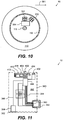
Figure 11 is a general illustration of a preferred embodiment in accordance with the invention depicting a schematic of the implementation of the present invention. - Referring to the illustrations, drawings and pictures,
reference character 10 generally designates a new and improved reel apparatus hat may generally maintain constant tension on a reel umbilical.Invention 10 is generally used with reels and or winches with offshore applications. For purposes of convenience, thereference numeral 10 may generally be utilized for the indication of the invention, portion of the invention, preferred embodiments of the invention and so forth. - Referring now to
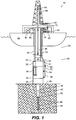
Fig. 1 , a view of a complete system for drillingsubsea wells 20 is shown in order to illustrate the utility of the present invention. Thedrilling riser 22 is shown with acentral pipe 24, outsidefluid lines 26, and umbilical, cable orhose 28. - Below the
drilling riser 22 is a flex joint 30, lowermarine riser package 32, lowerblowout preventer stack 34 and wellhead orwellhead system 36 landed on theseafloor 38. - Below the
wellhead 36, it can be seen that a hole was drilled for afirst casing string 40, thatfirst casing string 40 was landed and cemented in place, a hole drilled through thefirst casing string 40 for asecond casing string 42, thesecond casing string 42 cemented in place, and a hole is being drilled for a third casing string bydrill bit 44 ondrill string 46. - The lower
blowout preventer stack 34 generally comprises a lower hydraulic connector for connecting to thesubsea wellhead system 36, usually 4 or 5 ram style blowout preventers, an annular preventer, and an upper mandrel for connection by the connector on the lowermarine riser package 32, which are not individually shown but are well known in the art. - Below
outside fluid line 26 is a choke and kill (C&K)connector 50 and apipe 52, which is generally illustrative of a choke or kill line.Pipe 52 goes down tovalves drill string 46, through thedrill bit 44. - In normal drilling circulation, mud pumps 60 take
drilling mud 62 frommud tank 64. Thedrilling mud 60 will be pumped up astandpipe 66 and downupper end 68 of thedrill string 46. It will be pumped down thedrill string 46, out thedrill bit 44, and return up theannular area 70 between the outside of thedrill string 46 and the bore of the hole being drilled, up the bore of thesecond casing string 42, through thesubsea wellhead system 36, the lowerblowout preventer stack 34, the lowermarine riser package 32, up thedrilling riser 22, out a bell nipple 72 and back into themud tank 64. - During situations in which an abnormally high pressure from the formation has entered the well bore, the thin walled
central pipe 24 is typically not able to withstand the pressures involved. Rather than making the wall thickness of the relatively large bore drilling riser thick enough to withstand the pressure, the flow is diverted to a choke line oroutside fluid line 26. It is more economical to have a relatively thick wall in a small pipe to withstand the higher pressures than to have the proportionately thick wall in the larger riser pipe. - When higher pressures are to be contained, one of the annular or ram blowout preventers are closed around the drill pipe and the flow coming up the
annular area 70 around the drill pipe is diverted out throughchoke valve 54 into thepipe 52. The flow passes up throughC&K connector 50, up outsidefluid lines 26, which is attached to the outer diameter of thecentral pipe 24, through choking means illustrated at 74, and back into themud tank 64. - On the opposite side of the
drilling riser 22 is shown cable orhose 28 coming across asheave 80 from areel 82 onvessel 84. The cable orhose 28 is shown characteristically entering the top 90 of the lowermarine riser package 32. Thesecables 28 typically carry hydraulic, electrical, multiplex electrical, or fiber optic signals. Typically, there are at least two of thesecable 28 systems for redundancy, which are characteristically painted yellow and blue. As theumbilicals 28enter top 90 of the lowermarine riser package 32, they typically enter acontrol pod 92 to deliver their supply or signals. Hydraulic supply is delivered to one or more dualhydraulic accumulators 94 located on the lowermarine riser package 32 or the lowerblowout preventer stack 34 to store hydraulic fluid under pressure until needed. - Referring now to
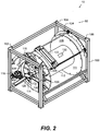
Fig. 2 , thereel 82 is shown in greater detail.Reel 82 hasframe 100, liftingpadeyes spool 110 havingflanges 111 and drum 112 mounted onaxle 113 andbearing 114, slipclutches 116,motor 118,swivel 120,levelwind assembly 122 mounted on banana shaped mounting 124,control box 126, and gear or sprocket 128. Swivel 120 can be hydraulic, electrical, fiber optic, or a combination of any of these. Gear or sprocket 128 is mounted onslip clutches 116 which are fixed tospool 110. - Also shown on
reel 82 areframe control module 130 andspool control module 132 which is shown insidespool 110. - Referring now to
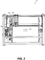
Fig. 3 , the relationship ofslip clutches 116 and theframe control module 130 is shown such that asspool 110 rotates, each of theslip clutches 116 pass nearframe control module 130. As will be discussed later, in an embodiment not covered by the present claims, each time a slip clutch 116 passes theframe control module 130, they will be detected and counted to determine both the number of rotations of thespool 110 and the direction of rotation of thespool 110. In accordance with the scope of the claims, accelerometers on or withinspool 110 will provide this capability. - Referring now to
Fig. 4 , slipclutches panel 126. This means that for each rotation of thespool 110,spool control module 132 will see four indications, so will divide the number by 4 to get the actual number of rotations. Access covers 134 and 136 are shown on the end ofspool 110. These give access to the inside of thespool 110 to install and servicespool control module 132. - Referring now to
Fig. 5 , a perspective view of one ofslip clutches 116 is seen, showing mountingbolts 150 to fix it to the side ofspool 110,brake pads cylinder 156, which provides controlled loading to regulate the frictional slipping load. - Referring now to
Fig. 6 , a view ofslip clutch 116 is shown according to the view "6-6" taken fromFig. 5 .Gap 158 is shown betweenbrake pads - Referring now to
Fig. 7 , a half section ofcylinder 156 is shown taken from section "7-7" ofFig. 6 .Spring washers 170 provide a force againstpiston 172, which in turn loadsbrake pad 152 throughend 174. Regulated air pressure throughport 176 onpiston area 178 provides a force to offset the force ofspring washers 170, regulating the force onend 174, and therefore,brake pad 152 to adjust the force required to cause gear or sprocket 128 to slip. Regulated air pressure throughport 180 and porting 182 inpiston 172 act onpiston area 184 ofpiston 172 to be additive to the force ofspring washers 170 when greater frictional force is desired.Piston cap 186 is rotated onthreads 188 to provide an initial mechanical adjustment to the magnitude of force fromspring washers 170. - Referring now to
Fig. 8 ,box 200 generally encompasses the mechanical components ofreel 82,box 202 generally encompasses the components of thelocal control panel 126,box 204 generally encompasses the components of theframe control module 130, andbox 206 generally encompasses the components of the driller's control panel. -
Box 200 includesspool 110,axle 113, slipclutches 116A to 116D,air swivel 210,air supply 212,air shutoff valve 214,air motor 216 with gear orsprocket 218 mounted, driven gear orsprocket 220, and levelwind drivemotor 222. Driven gear orsprocket 220 is shown aligned with gear orsprocket 218 and is also shown with a face view having fourprotrusions 224 at 90 degrees. Theprotrusions 224 are likely a portion of theslip clutches 116 but they can be other quantities and other components.Brakes 226 are shown and will be operated bycontrol box 126. -
Box 202 includes the components of a pneumatic control box which would provide constant torque control of a reel, and some components which change it to having constant tension operation, as will be described as follows. -
Box 204 is the control box which includes the components which convert the reel to constant tension operation. Proximity sensor(s) or sensing component(s) 230 and 232 can be acoustic, laser, microwave, or other means to detect when theprotrusions 224 pass by. Further they are positioned such that both will senseprotrusion 224 one after the other, but the second to senseprotrusion 224 will also sense before the first stops sensing.Sensing component 230 is the primary sensing component andsensing component 232 is the secondary sensing component. When sensingcomponent 230 first senses one of theprotrusions 224,sensing component 232 will be checked to see if it is sensing at the same time. Ifsensing component 232 is sensing when sensingcomponent 230starts sensing protrusion 224, it will mean that the reel is rotating in the take-up direction. Ifsensing component 232 is not sensing when sensingcomponent 230starts sensing protrusion 224, it will mean that the reel is rotating in the payout direction. - Processing
computer 240 is initially set up with inputs on the spool drum diameter, spool width, spool flange diameter, umbilical diameter, the starting dimension from the outer diameter of the spool flange, and the distance from the side of the spool flange to the current umbilical position. Theprocessing computer 240 receives the indications from sensingcomponents port 176 ofFig. 7 to set the appropriate slippage setting. The general goal of these calculations is to end up with a constant tension pull on the umbilical, e.g. 453.6 kg (1000 lbs.), and an appropriate slippage setting on the spool, e.g. 680.4 kg (1,500 lbs.) umbilical tension. This umbilical tension setting and slippage setting is to remain relatively constant from a full spool starting the lowering of the blowout preventer stack to its landing on the seafloor and back up to the surface. This not only involves the fact that the motor torque and slippage settings must change each time the umbilical starts on new wrap level, but also that simply reversing the reel has frictional hysteresis assisting you in one direction and working against you in the other direction. - The computed appropriate motor air pressure is sent to the motor along
line 250 toselector valve 252, to largebore pressure regulator 254, through largebore selector valve 256, and then toair motor 216. The method of generating the appropriate air motor pressure signals is to measure the pressure inline 250 usingpressure transmitter 260 and sending the information back to theprocessing computer 240 alongwire 262. If the air pressure inline 250 is low, processingcomputer 240 sends a signal throughwire 264 tovalve 266 to temporarily open the valve and let the higher supply pressure insupply line 268 vent intoline 250. If the air pressure inline 250 is low, processingcomputer 240 sends a signal throughwire 270 tovalve 272 to temporarily open the valve and vent the pressure inline 250 to reduce the pressure. Processingcomputer 240 is programmed in a repetitive loop, so it will repeatedly check the pressure inline 250 throughpressure transmitter 260, continually making sure the pressure inline 250 is within the required pressure band. - When deploying the umbilical and all the umbilical is deployed for a wrap and the reel starts to deploy from the next lower wrap, the radius is reduced so the spool/motor torque requirement is reduced. At that time the
computer 240 computes the lower pressure required forline 250 and begins pulsingvalve 272 until the pressure is in the proper range. Alternately, when recovering the umbilical as the blowout preventer stack returns to the surface and the umbilical begins wrapping on the next higher layer, thecomputer 240 begins pulsingvalve 266 to increase the pressure inline 250 to the required computed level. - Similarly a signal is calculated by processing
computer 240 and built inline 280 forslip clutches pressure transmitter 282,valve 284 to increase the pressure, andvalve 286 to reduce the pressure. In this case the signal inline 280 is communicated to theslip clutches air swivel 210.Air swivel 210 can be made integrally with theaxle 113 or can be a slip onair swivel 210 as is illustrated inFig. 8 . -
Box 206 shows asingle valve 290, which is mounted in a remote location such as the driller's control house.Valve 290 is a two position detented valve and in the present position, the pressure inline 292 is simply vented. This means that the air signal inline 250 will be communicated throughvalve 252 toregulator 254 and sets the pressure on the motor as determined by theprocessing computer 240. Similarly, the air signal inline 280 will be communicated throughvalve 298 to theslip clutches processing computer 240. Whenvalve 290 is moved to the alternated detent position, higher pressure air supply fromline 294 is introduced intoline 292 shiftingvalve 252 to allow the pressure from themanual throttle 296 to control the motor pressure and shiftingvalve 298 to vent the air pressure from theslip clutches Valve 300 is the brake control valve. -
Infrared port 302 is used to refresh the computer program inprocess computer 240 throughline 304 when an upload module as will be described later is engaged withprofile 306 for proper alignment. - Referring now to
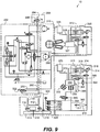
Fig. 9 , a schematic similar toFig. 8 is illustrated, withboxes Reel box 200 is replaced withreel box 310 andbox 204 is replaced withbox 312 andbox 314. -
Box 314 is also shown to be located insidespool 110 as shown inbox 310 rather than on the frame asbox 312 andbox 204 are. Whereasbox 204 provided asingle processing computer 240 to control both the motor pressure and the slip clutch pressure, in thisconfiguration box 312 controls the motor pressure andbox 314 controls the slip clutch pressure. One effect of this is that the signal is going through the swivel in the opposite direction, and another is that you no longer need a swivel if you makebattery pack 315 withinbox 314 large enough to run several trips to the seafloor or sufficient air supply can be supplied inair tank 316 throughconnector 317 orair swivel 210 topower air motor 318, which drivesgenerator 319 to keep thebattery pack 315 charged. -
Box 310 shows that theair supply line 268 is taken byair line 320, throughvalve 322,line 324 and exits from theair swivel 210 asair line 326, which goes to power thebox 314. Whenever thevalve 290 inbox 206 is actuated and applies pressure toline 292,valve 322 is shifted and the pressure inlines -
Box 312 includes all the components ofbox 204 ofFig. 8 except thecomponents slip clutches box 314. -
Infrared port 325 is used to refresh the computer program inprocess computer 327 throughline 328 when an upload module as will be described later in engaged withprofile 330 for proper alignment. -
Box 314 is located within the spool 110 (as shown in box 310), it does not have the reference information whichbox 204 provided. Accelerometers 350 and 352 are provided to detect rotations and rotational direction as will be described later. As was done inFig. 8 , this will be used to determine whether the umbilical is going to the next outer or the next inner wrap when it reaches either of the side flanges on the spool. - The computation of the needed slip clutch pressure is done in
process computer 354 and sent to theslip clutches lines Valve 359 is provided betweenlines supply air line 326 alongline 360 to allow the computed signal to pass. If the supply pressure is reduced to zero, the supply signal inline 360 is vented and the reel returns to constant torque operation. - A signal is calculated by processing
computer 354 and built inline 356 forslip clutches pressure transmitter 362,valve 364 to increase the pressure, andvalve 366 to reduce the pressure, similarly aspressure transmitter 282,valve 284, andvalve 286 were used inFig. 8 . -
Infrared port 370 is used to refresh the computer program inprocess computer 354 throughline 372 when an upload module as will be described later is engaged withprofile 374 for proper alignment. - Referring now to
Fig. 10 , in one full rotation ofspool 110, the accelerometers will see plus one g's and minus one g's and can count the g cycles as rotations. Whenprimary accelerometer 331 is at one-g displaced as shown,secondary accelerometer 332 can be positioned at 45 degrees as shown towards thepayout direction 361. This angle is an example, the actual angle can be any angle other than 0 degrees, 90 degrees, 180 degrees, or 270 degrees. When theprimary accelerometer 331 is at zero-g's, whether thesecondary accelerometer 332 is reading plus one or minus one-g's will tell the direction of rotation. In this case, if the g-readings are declining it will mean that thespool 110 is rotating in the payout direction. If the g-readings are increasing it will mean that thespool 110 is rotating in the take-up direction. This information can be fed back into theprocess computer 354 to determine when the umbilical comes to the end of a wrapping a layer whether to add to the radius to the umbilical or to subtract from it. - Referring now to
Fig. 11 , an uploadmodule 380 which as aprofile 382 for convenient engagement and alignment withprofiles process computers Infrared transmitter 384 engagesinfrared port Process computer 388 is uploaded from a standard computer through a USB orother port 390 which is made explosion proof by anappropriate cap protector 392.Lines 394 connect theport 390 to processcomputer 388 andline 396 in turn connectsprocess computer 388 to theinfrared port 384. - When upload
module 380 is taken to refresh a process computer on the reel, it will often be in the hazardous explosion prone area of an offshore drilling rig. For this reason all modules used need to be explosion proof. In this case the switches required to operate the upload models are magnetic switches buried insolid potting material 397. The other modules described before will likely be of the same construction.Magnet 400 is used to operate the switches with functions such as off and on 402, enter, upload in uploadmode 404 or download indownload mode 406, increase reading 408, and decrease reading 410.Readout 412 will display the readings of the current mode being adjusted. Likely only the off and on, upload, and download buttons will be used and most programming will simply be input throughport 390. - The particular embodiments disclosed above are illustrative only, as the invention may be modified and practiced in different but equivalent manners apparent to those skilled in the art having the benefit of the teachings herein. Furthermore, no limitations are intended to the details of construction or design herein shown, other than as described in the claims below. It is therefore evident that the particular embodiments disclosed above may be altered or modified. Accordingly, the protection sought herein is as set forth in the claims below.
Claims (3)
- A reel assembly for an offshore umbilical comprising:a frame (100) having an axle (113);a spool (110) having flanges (111) and a drum wherein said spool (110) is mounted on said axle (113) and adapted to hold said offshore umbilical;a motor (118) in communication with said spool (110) and adapted to rotate said spool (110);a tensioning device adapted to automatically maintain a relatively constant tension and a relatively constant slippage load on said umbilical when deployed from said spool (110), wherein said tensioning device comprises:a primary accelerometer (331) attached to said spool (110) anda secondary accelerometer (332) which is attached to said spool (110) at an angle from the primary accelerometer wherein the primary accelerometer (331) and the secondary accelerometer (332) are arranged to detect rotational direction of said spool (110); anda processing computer in communication with the primary accelerometer (331), the secondary accelerometer (332) and the motor (118) wherein the processing computer is adapted to compute the relative constant tension and the relative constant slippage and control the motor (118) based on g force readings of the primary accelerometer (331) and the secondary accelerometer (332).
- The reel assembly of claim 1 wherein said tensioning device includes at least one slip clutch (116) attached to said frame (100), adapted to engage said spool (110), and in communication with said processing computer.
- The reel assembly of claim 1 further including a computer module in wireless communication with said processing computer.
Applications Claiming Priority (4)
| Application Number | Priority Date | Filing Date | Title |
|---|---|---|---|
| US201562174348P | 2015-06-11 | 2015-06-11 | |
| US201562174368P | 2015-06-11 | 2015-06-11 | |
| US201562174363P | 2015-06-11 | 2015-06-11 | |
| PCT/US2016/000046 WO2016200437A1 (en) | 2015-06-11 | 2016-06-09 | Self-adjusting reel assembly apparatus, system and method |
Publications (3)
| Publication Number | Publication Date |
|---|---|
| EP3307663A1 EP3307663A1 (en) | 2018-04-18 |
| EP3307663A4 EP3307663A4 (en) | 2019-03-20 |
| EP3307663B1 true EP3307663B1 (en) | 2021-02-24 |
Family
ID=61099711
Family Applications (1)
| Application Number | Title | Priority Date | Filing Date |
|---|---|---|---|
| EP16807934.1A Active EP3307663B1 (en) | 2015-06-11 | 2016-06-09 | Self-adjusting reel assembly apparatus, system and method |
Country Status (3)
| Country | Link |
|---|---|
| EP (1) | EP3307663B1 (en) |
| CN (1) | CN107635900B (en) |
| DK (1) | DK3307663T3 (en) |
Families Citing this family (2)
| Publication number | Priority date | Publication date | Assignee | Title |
|---|---|---|---|---|
| CN110454103B (en) * | 2019-09-16 | 2024-09-13 | 华信唐山石油装备有限公司 | High-capacity logging composite pipe cable roller device |
| CN112499380B (en) * | 2020-12-16 | 2023-04-07 | 西格码电气股份有限公司 | Automatic take-up device for electric power engineering |
Family Cites Families (8)
| Publication number | Priority date | Publication date | Assignee | Title |
|---|---|---|---|---|
| US5950953A (en) * | 1998-01-27 | 1999-09-14 | Benton F. Baugh | Reel with adjustable fleet angle |
| FR2847667B1 (en) * | 2002-11-22 | 2005-01-07 | Siemens Vdo Automotive | DEVICE FOR DETECTING THE POSITION OF A VEHICLE WHEEL |
| CN101891088A (en) * | 2004-07-01 | 2010-11-24 | 巨杰公司 | Be used to promote the automatic reel of the winding of linear material |
| WO2007079264A2 (en) * | 2005-12-30 | 2007-07-12 | Overend Technologies, Llc | Unwind and feed system for elastomeric thread |
| US8136383B2 (en) * | 2007-08-28 | 2012-03-20 | Westerngeco L.L.C. | Calibrating an accelerometer |
| US20110006149A1 (en) * | 2009-07-07 | 2011-01-13 | Benton Frederick Baugh | Method for automatic cable tension on a reel |
| US7967234B2 (en) * | 2009-07-07 | 2011-06-28 | Baugh Benton F | Method for automatic slip clutch tension on a reel |
| US9802787B2 (en) * | 2013-09-20 | 2017-10-31 | Reel Power Licensing Corp. | Method of providing a clutch for a spool |
-
2016
- 2016-06-09 CN CN201680033580.1A patent/CN107635900B/en active Active
- 2016-06-09 EP EP16807934.1A patent/EP3307663B1/en active Active
- 2016-06-09 DK DK16807934.1T patent/DK3307663T3/en active
Non-Patent Citations (1)
| Title |
|---|
| None * |
Also Published As
| Publication number | Publication date |
|---|---|
| EP3307663A1 (en) | 2018-04-18 |
| EP3307663A4 (en) | 2019-03-20 |
| DK3307663T3 (en) | 2021-04-06 |
| CN107635900A (en) | 2018-01-26 |
| CN107635900B (en) | 2019-10-29 |
Similar Documents
| Publication | Publication Date | Title |
|---|---|---|
| US9689215B2 (en) | Self-adjusting reel assembly apparatus, system and method | |
| US10151770B2 (en) | Method for constant tension and slippage setting on a reel using accelerometers to detect rotational direction | |
| US9714550B2 (en) | Method for constant tension and slippage setting on a reel using proximity sensors to detect rotational direction | |
| US20160362945A1 (en) | Method of maintaining constant tension on a reel umbilical | |
| US7967234B2 (en) | Method for automatic slip clutch tension on a reel | |
| US9151123B2 (en) | Apparatus and methods for providing tubing into a subsea well | |
| US4577693A (en) | Wireline apparatus | |
| US6276454B1 (en) | Tubing injection systems for oilfield operations | |
| US6968905B2 (en) | Distributed control system | |
| US20110006149A1 (en) | Method for automatic cable tension on a reel | |
| US10689922B2 (en) | System and method for providing tension or heave compensation in an offshore drilling environment | |
| US10494880B2 (en) | Electronically controlled reel system for oilfield operations | |
| US7363968B1 (en) | Umbilical reel safety release | |
| EP3307663B1 (en) | Self-adjusting reel assembly apparatus, system and method | |
| US20110198431A1 (en) | Method to improve brake closing response time | |
| NO315129B1 (en) | Pipeline injection system for oilfield operations | |
| US10619428B2 (en) | Method and apparatus for automated connection of a fluid conduit | |
| EP3642447B1 (en) | Method and apparatus for automated connection of a fluid conduit |
Legal Events
| Date | Code | Title | Description |
|---|---|---|---|
| STAA | Information on the status of an ep patent application or granted ep patent |
Free format text: STATUS: THE INTERNATIONAL PUBLICATION HAS BEEN MADE |
|
| PUAI | Public reference made under article 153(3) epc to a published international application that has entered the european phase |
Free format text: ORIGINAL CODE: 0009012 |
|
| STAA | Information on the status of an ep patent application or granted ep patent |
Free format text: STATUS: REQUEST FOR EXAMINATION WAS MADE |
|
| 17P | Request for examination filed |
Effective date: 20171117 |
|
| AK | Designated contracting states |
Kind code of ref document: A1 Designated state(s): AL AT BE BG CH CY CZ DE DK EE ES FI FR GB GR HR HU IE IS IT LI LT LU LV MC MK MT NL NO PL PT RO RS SE SI SK SM TR |
|
| AX | Request for extension of the european patent |
Extension state: BA ME |
|
| RIN1 | Information on inventor provided before grant (corrected) |
Inventor name: BAUGH, BENTON, FREDERICK |
|
| DAV | Request for validation of the european patent (deleted) | ||
| DAX | Request for extension of the european patent (deleted) | ||
| A4 | Supplementary search report drawn up and despatched |
Effective date: 20190214 |
|
| RIC1 | Information provided on ipc code assigned before grant |
Ipc: B65H 57/14 20060101ALI20190208BHEP Ipc: B65H 54/28 20060101AFI20190208BHEP Ipc: E21B 19/00 20060101ALI20190208BHEP Ipc: E21B 19/22 20060101ALI20190208BHEP Ipc: B65H 59/02 20060101ALI20190208BHEP Ipc: E21B 23/14 20060101ALI20190208BHEP |
|
| STAA | Information on the status of an ep patent application or granted ep patent |
Free format text: STATUS: EXAMINATION IS IN PROGRESS |
|
| 17Q | First examination report despatched |
Effective date: 20191213 |
|
| GRAP | Despatch of communication of intention to grant a patent |
Free format text: ORIGINAL CODE: EPIDOSNIGR1 |
|
| STAA | Information on the status of an ep patent application or granted ep patent |
Free format text: STATUS: GRANT OF PATENT IS INTENDED |
|
| RIC1 | Information provided on ipc code assigned before grant |
Ipc: E21B 19/00 20060101ALI20200812BHEP Ipc: B65H 59/02 20060101ALI20200812BHEP Ipc: F16D 65/092 20060101ALI20200812BHEP Ipc: B65H 54/28 20060101AFI20200812BHEP Ipc: E21B 19/22 20060101ALI20200812BHEP Ipc: B65H 57/14 20060101ALI20200812BHEP Ipc: E21B 23/14 20060101ALI20200812BHEP |
|
| INTG | Intention to grant announced |
Effective date: 20200910 |
|
| GRAS | Grant fee paid |
Free format text: ORIGINAL CODE: EPIDOSNIGR3 |
|
| GRAA | (expected) grant |
Free format text: ORIGINAL CODE: 0009210 |
|
| STAA | Information on the status of an ep patent application or granted ep patent |
Free format text: STATUS: THE PATENT HAS BEEN GRANTED |
|
| AK | Designated contracting states |
Kind code of ref document: B1 Designated state(s): AL AT BE BG CH CY CZ DE DK EE ES FI FR GB GR HR HU IE IS IT LI LT LU LV MC MK MT NL NO PL PT RO RS SE SI SK SM TR |
|
| REG | Reference to a national code |
Ref country code: CH Ref legal event code: EP |
|
| REG | Reference to a national code |
Ref country code: AT Ref legal event code: REF Ref document number: 1364190 Country of ref document: AT Kind code of ref document: T Effective date: 20210315 |
|
| REG | Reference to a national code |
Ref country code: IE Ref legal event code: FG4D |
|
| REG | Reference to a national code |
Ref country code: DE Ref legal event code: R096 Ref document number: 602016053220 Country of ref document: DE |
|
| REG | Reference to a national code |
Ref country code: DK Ref legal event code: T3 Effective date: 20210330 |
|
| REG | Reference to a national code |
Ref country code: NO Ref legal event code: T2 Effective date: 20210224 |
|
| REG | Reference to a national code |
Ref country code: LT Ref legal event code: MG9D |
|
| REG | Reference to a national code |
Ref country code: NL Ref legal event code: MP Effective date: 20210224 |
|
| PG25 | Lapsed in a contracting state [announced via postgrant information from national office to epo] |
Ref country code: LT Free format text: LAPSE BECAUSE OF FAILURE TO SUBMIT A TRANSLATION OF THE DESCRIPTION OR TO PAY THE FEE WITHIN THE PRESCRIBED TIME-LIMIT Effective date: 20210224 Ref country code: BG Free format text: LAPSE BECAUSE OF FAILURE TO SUBMIT A TRANSLATION OF THE DESCRIPTION OR TO PAY THE FEE WITHIN THE PRESCRIBED TIME-LIMIT Effective date: 20210524 Ref country code: HR Free format text: LAPSE BECAUSE OF FAILURE TO SUBMIT A TRANSLATION OF THE DESCRIPTION OR TO PAY THE FEE WITHIN THE PRESCRIBED TIME-LIMIT Effective date: 20210224 Ref country code: GR Free format text: LAPSE BECAUSE OF FAILURE TO SUBMIT A TRANSLATION OF THE DESCRIPTION OR TO PAY THE FEE WITHIN THE PRESCRIBED TIME-LIMIT Effective date: 20210525 Ref country code: FI Free format text: LAPSE BECAUSE OF FAILURE TO SUBMIT A TRANSLATION OF THE DESCRIPTION OR TO PAY THE FEE WITHIN THE PRESCRIBED TIME-LIMIT Effective date: 20210224 Ref country code: PT Free format text: LAPSE BECAUSE OF FAILURE TO SUBMIT A TRANSLATION OF THE DESCRIPTION OR TO PAY THE FEE WITHIN THE PRESCRIBED TIME-LIMIT Effective date: 20210624 |
|
| REG | Reference to a national code |
Ref country code: AT Ref legal event code: MK05 Ref document number: 1364190 Country of ref document: AT Kind code of ref document: T Effective date: 20210224 |
|
| PG25 | Lapsed in a contracting state [announced via postgrant information from national office to epo] |
Ref country code: RS Free format text: LAPSE BECAUSE OF FAILURE TO SUBMIT A TRANSLATION OF THE DESCRIPTION OR TO PAY THE FEE WITHIN THE PRESCRIBED TIME-LIMIT Effective date: 20210224 Ref country code: PL Free format text: LAPSE BECAUSE OF FAILURE TO SUBMIT A TRANSLATION OF THE DESCRIPTION OR TO PAY THE FEE WITHIN THE PRESCRIBED TIME-LIMIT Effective date: 20210224 Ref country code: LV Free format text: LAPSE BECAUSE OF FAILURE TO SUBMIT A TRANSLATION OF THE DESCRIPTION OR TO PAY THE FEE WITHIN THE PRESCRIBED TIME-LIMIT Effective date: 20210224 Ref country code: NL Free format text: LAPSE BECAUSE OF FAILURE TO SUBMIT A TRANSLATION OF THE DESCRIPTION OR TO PAY THE FEE WITHIN THE PRESCRIBED TIME-LIMIT Effective date: 20210224 Ref country code: SE Free format text: LAPSE BECAUSE OF FAILURE TO SUBMIT A TRANSLATION OF THE DESCRIPTION OR TO PAY THE FEE WITHIN THE PRESCRIBED TIME-LIMIT Effective date: 20210224 |
|
| PG25 | Lapsed in a contracting state [announced via postgrant information from national office to epo] |
Ref country code: IS Free format text: LAPSE BECAUSE OF FAILURE TO SUBMIT A TRANSLATION OF THE DESCRIPTION OR TO PAY THE FEE WITHIN THE PRESCRIBED TIME-LIMIT Effective date: 20210624 |
|
| PG25 | Lapsed in a contracting state [announced via postgrant information from national office to epo] |
Ref country code: AT Free format text: LAPSE BECAUSE OF FAILURE TO SUBMIT A TRANSLATION OF THE DESCRIPTION OR TO PAY THE FEE WITHIN THE PRESCRIBED TIME-LIMIT Effective date: 20210224 Ref country code: SM Free format text: LAPSE BECAUSE OF FAILURE TO SUBMIT A TRANSLATION OF THE DESCRIPTION OR TO PAY THE FEE WITHIN THE PRESCRIBED TIME-LIMIT Effective date: 20210224 Ref country code: CZ Free format text: LAPSE BECAUSE OF FAILURE TO SUBMIT A TRANSLATION OF THE DESCRIPTION OR TO PAY THE FEE WITHIN THE PRESCRIBED TIME-LIMIT Effective date: 20210224 Ref country code: EE Free format text: LAPSE BECAUSE OF FAILURE TO SUBMIT A TRANSLATION OF THE DESCRIPTION OR TO PAY THE FEE WITHIN THE PRESCRIBED TIME-LIMIT Effective date: 20210224 |
|
| REG | Reference to a national code |
Ref country code: DE Ref legal event code: R097 Ref document number: 602016053220 Country of ref document: DE |
|
| PG25 | Lapsed in a contracting state [announced via postgrant information from national office to epo] |
Ref country code: SK Free format text: LAPSE BECAUSE OF FAILURE TO SUBMIT A TRANSLATION OF THE DESCRIPTION OR TO PAY THE FEE WITHIN THE PRESCRIBED TIME-LIMIT Effective date: 20210224 Ref country code: RO Free format text: LAPSE BECAUSE OF FAILURE TO SUBMIT A TRANSLATION OF THE DESCRIPTION OR TO PAY THE FEE WITHIN THE PRESCRIBED TIME-LIMIT Effective date: 20210224 |
|
| PLBE | No opposition filed within time limit |
Free format text: ORIGINAL CODE: 0009261 |
|
| STAA | Information on the status of an ep patent application or granted ep patent |
Free format text: STATUS: NO OPPOSITION FILED WITHIN TIME LIMIT |
|
| PG25 | Lapsed in a contracting state [announced via postgrant information from national office to epo] |
Ref country code: ES Free format text: LAPSE BECAUSE OF FAILURE TO SUBMIT A TRANSLATION OF THE DESCRIPTION OR TO PAY THE FEE WITHIN THE PRESCRIBED TIME-LIMIT Effective date: 20210224 Ref country code: AL Free format text: LAPSE BECAUSE OF FAILURE TO SUBMIT A TRANSLATION OF THE DESCRIPTION OR TO PAY THE FEE WITHIN THE PRESCRIBED TIME-LIMIT Effective date: 20210224 Ref country code: MC Free format text: LAPSE BECAUSE OF FAILURE TO SUBMIT A TRANSLATION OF THE DESCRIPTION OR TO PAY THE FEE WITHIN THE PRESCRIBED TIME-LIMIT Effective date: 20210224 |
|
| REG | Reference to a national code |
Ref country code: CH Ref legal event code: PL |
|
| 26N | No opposition filed |
Effective date: 20211125 |
|
| PG25 | Lapsed in a contracting state [announced via postgrant information from national office to epo] |
Ref country code: SI Free format text: LAPSE BECAUSE OF FAILURE TO SUBMIT A TRANSLATION OF THE DESCRIPTION OR TO PAY THE FEE WITHIN THE PRESCRIBED TIME-LIMIT Effective date: 20210224 |
|
| REG | Reference to a national code |
Ref country code: BE Ref legal event code: MM Effective date: 20210630 |
|
| PG25 | Lapsed in a contracting state [announced via postgrant information from national office to epo] |
Ref country code: LU Free format text: LAPSE BECAUSE OF NON-PAYMENT OF DUE FEES Effective date: 20210609 |
|
| PG25 | Lapsed in a contracting state [announced via postgrant information from national office to epo] |
Ref country code: LI Free format text: LAPSE BECAUSE OF NON-PAYMENT OF DUE FEES Effective date: 20210630 Ref country code: IT Free format text: LAPSE BECAUSE OF FAILURE TO SUBMIT A TRANSLATION OF THE DESCRIPTION OR TO PAY THE FEE WITHIN THE PRESCRIBED TIME-LIMIT Effective date: 20210224 Ref country code: IE Free format text: LAPSE BECAUSE OF NON-PAYMENT OF DUE FEES Effective date: 20210609 Ref country code: CH Free format text: LAPSE BECAUSE OF NON-PAYMENT OF DUE FEES Effective date: 20210630 |
|
| PG25 | Lapsed in a contracting state [announced via postgrant information from national office to epo] |
Ref country code: IS Free format text: LAPSE BECAUSE OF FAILURE TO SUBMIT A TRANSLATION OF THE DESCRIPTION OR TO PAY THE FEE WITHIN THE PRESCRIBED TIME-LIMIT Effective date: 20210624 |
|
| PG25 | Lapsed in a contracting state [announced via postgrant information from national office to epo] |
Ref country code: BE Free format text: LAPSE BECAUSE OF NON-PAYMENT OF DUE FEES Effective date: 20210630 |
|
| PG25 | Lapsed in a contracting state [announced via postgrant information from national office to epo] |
Ref country code: CY Free format text: LAPSE BECAUSE OF FAILURE TO SUBMIT A TRANSLATION OF THE DESCRIPTION OR TO PAY THE FEE WITHIN THE PRESCRIBED TIME-LIMIT Effective date: 20210224 |
|
| PG25 | Lapsed in a contracting state [announced via postgrant information from national office to epo] |
Ref country code: HU Free format text: LAPSE BECAUSE OF FAILURE TO SUBMIT A TRANSLATION OF THE DESCRIPTION OR TO PAY THE FEE WITHIN THE PRESCRIBED TIME-LIMIT; INVALID AB INITIO Effective date: 20160609 |
|
| PGFP | Annual fee paid to national office [announced via postgrant information from national office to epo] |
Ref country code: NO Payment date: 20230629 Year of fee payment: 8 |
|
| PG25 | Lapsed in a contracting state [announced via postgrant information from national office to epo] |
Ref country code: MK Free format text: LAPSE BECAUSE OF FAILURE TO SUBMIT A TRANSLATION OF THE DESCRIPTION OR TO PAY THE FEE WITHIN THE PRESCRIBED TIME-LIMIT Effective date: 20210224 |
|
| PG25 | Lapsed in a contracting state [announced via postgrant information from national office to epo] |
Ref country code: TR Free format text: LAPSE BECAUSE OF FAILURE TO SUBMIT A TRANSLATION OF THE DESCRIPTION OR TO PAY THE FEE WITHIN THE PRESCRIBED TIME-LIMIT Effective date: 20210224 |
|
| PGFP | Annual fee paid to national office [announced via postgrant information from national office to epo] |
Ref country code: GB Payment date: 20240628 Year of fee payment: 9 |
|
| PGFP | Annual fee paid to national office [announced via postgrant information from national office to epo] |
Ref country code: DE Payment date: 20240628 Year of fee payment: 9 |
|
| PGFP | Annual fee paid to national office [announced via postgrant information from national office to epo] |
Ref country code: DK Payment date: 20240627 Year of fee payment: 9 |
|
| PGFP | Annual fee paid to national office [announced via postgrant information from national office to epo] |
Ref country code: FR Payment date: 20240628 Year of fee payment: 9 |