EP3307637B1 - Filling station and method for filling cartridges of electronic cigarettes - Google Patents
Filling station and method for filling cartridges of electronic cigarettes Download PDFInfo
- Publication number
- EP3307637B1 EP3307637B1 EP16742032.2A EP16742032A EP3307637B1 EP 3307637 B1 EP3307637 B1 EP 3307637B1 EP 16742032 A EP16742032 A EP 16742032A EP 3307637 B1 EP3307637 B1 EP 3307637B1
- Authority
- EP
- European Patent Office
- Prior art keywords
- filling
- cartridges
- rotary
- cartridge
- conveyor
- Prior art date
- Legal status (The legal status is an assumption and is not a legal conclusion. Google has not performed a legal analysis and makes no representation as to the accuracy of the status listed.)
- Active
Links
- 239000003571 electronic cigarette Substances 0.000 title claims description 13
- 238000000034 method Methods 0.000 title claims description 13
- 238000003032 molecular docking Methods 0.000 claims description 43
- 239000007788 liquid Substances 0.000 claims description 30
- 238000011144 upstream manufacturing Methods 0.000 claims description 23
- 230000033001 locomotion Effects 0.000 claims description 18
- 230000000712 assembly Effects 0.000 claims description 16
- 238000000429 assembly Methods 0.000 claims description 16
- 238000005259 measurement Methods 0.000 claims description 16
- 230000008878 coupling Effects 0.000 claims description 8
- 238000010168 coupling process Methods 0.000 claims description 8
- 238000005859 coupling reaction Methods 0.000 claims description 8
- 230000032258 transport Effects 0.000 description 24
- 238000006243 chemical reaction Methods 0.000 description 9
- 230000013011 mating Effects 0.000 description 4
- 230000002093 peripheral effect Effects 0.000 description 4
- 239000003708 ampul Substances 0.000 description 3
- SNICXCGAKADSCV-JTQLQIEISA-N (-)-Nicotine Chemical compound CN1CCC[C@H]1C1=CC=CN=C1 SNICXCGAKADSCV-JTQLQIEISA-N 0.000 description 2
- 235000019568 aromas Nutrition 0.000 description 2
- 238000010586 diagram Methods 0.000 description 2
- 238000005429 filling process Methods 0.000 description 2
- 229960002715 nicotine Drugs 0.000 description 2
- SNICXCGAKADSCV-UHFFFAOYSA-N nicotine Natural products CN1CCCC1C1=CC=CN=C1 SNICXCGAKADSCV-UHFFFAOYSA-N 0.000 description 2
- 239000000654 additive Substances 0.000 description 1
- 230000005540 biological transmission Effects 0.000 description 1
- 238000010276 construction Methods 0.000 description 1
- 230000001419 dependent effect Effects 0.000 description 1
- 239000007903 gelatin capsule Substances 0.000 description 1
- 239000012263 liquid product Substances 0.000 description 1
- 239000000463 material Substances 0.000 description 1
- 235000013550 pizza Nutrition 0.000 description 1
- 239000007787 solid Substances 0.000 description 1
Images


Classifications
-
- B—PERFORMING OPERATIONS; TRANSPORTING
- B65—CONVEYING; PACKING; STORING; HANDLING THIN OR FILAMENTARY MATERIAL
- B65B—MACHINES, APPARATUS OR DEVICES FOR, OR METHODS OF, PACKAGING ARTICLES OR MATERIALS; UNPACKING
- B65B3/00—Packaging plastic material, semiliquids, liquids or mixed solids and liquids, in individual containers or receptacles, e.g. bags, sacks, boxes, cartons, cans, or jars
- B65B3/003—Filling medical containers such as ampoules, vials, syringes or the like
-
- B—PERFORMING OPERATIONS; TRANSPORTING
- B65—CONVEYING; PACKING; STORING; HANDLING THIN OR FILAMENTARY MATERIAL
- B65B—MACHINES, APPARATUS OR DEVICES FOR, OR METHODS OF, PACKAGING ARTICLES OR MATERIALS; UNPACKING
- B65B59/00—Arrangements to enable machines to handle articles of different sizes, to produce packages of different sizes, to vary the contents of packages, to handle different types of packaging material, or to give access for cleaning or maintenance purposes
- B65B59/001—Arrangements to enable adjustments related to the product to be packaged
-
- B—PERFORMING OPERATIONS; TRANSPORTING
- B65—CONVEYING; PACKING; STORING; HANDLING THIN OR FILAMENTARY MATERIAL
- B65B—MACHINES, APPARATUS OR DEVICES FOR, OR METHODS OF, PACKAGING ARTICLES OR MATERIALS; UNPACKING
- B65B59/00—Arrangements to enable machines to handle articles of different sizes, to produce packages of different sizes, to vary the contents of packages, to handle different types of packaging material, or to give access for cleaning or maintenance purposes
- B65B59/003—Arrangements to enable adjustments related to the packaging material
-
- B—PERFORMING OPERATIONS; TRANSPORTING
- B65—CONVEYING; PACKING; STORING; HANDLING THIN OR FILAMENTARY MATERIAL
- B65B—MACHINES, APPARATUS OR DEVICES FOR, OR METHODS OF, PACKAGING ARTICLES OR MATERIALS; UNPACKING
- B65B59/00—Arrangements to enable machines to handle articles of different sizes, to produce packages of different sizes, to vary the contents of packages, to handle different types of packaging material, or to give access for cleaning or maintenance purposes
- B65B59/04—Machines constructed with readily-detachable units or assemblies, e.g. to facilitate maintenance
-
- B—PERFORMING OPERATIONS; TRANSPORTING
- B65—CONVEYING; PACKING; STORING; HANDLING THIN OR FILAMENTARY MATERIAL
- B65B—MACHINES, APPARATUS OR DEVICES FOR, OR METHODS OF, PACKAGING ARTICLES OR MATERIALS; UNPACKING
- B65B2210/00—Specific aspects of the packaging machine
- B65B2210/02—Plurality of alternative input or output lines or plurality of alternative packaging units on the same packaging line for improving machine flexibility
Definitions
- the present invention relates to a filling station for cartridges of electronic cigarettes and to a method of filling cartridges of electronic cigarettes with a liquid in a filling station.
- Filling stations for cartridges of electronic cigarettes are known.
- Disposable electronic-cigarette cartridges are generally filled in a filling line.
- the cartridges contain a wad (also referred to as a non-woven). During the filling, the wad is impregnated with the liquid.
- the liquid may contain nicotine and/or aromas.
- the cartridges are generally filled by conveying the cartridges with the opening directed upward. The cartridges are conveyed to a filling station and are filled with a predetermined volume of the liquid.
- EP0579480 discloses a filling station 15 for filling ampules, see in particular elements 13,15 in figures 1 and 12 and elements 127 in fig. 20.
- Figure 12 shows that the filling station is mounted via a beam on a central drive shaft 84. See also column 10, lines 13-23 of EP0579480 .
- the idea behind this configuration is that the ampules which are conveyed by a turntable 13 make a continuous rotary motion and that the nozzles 127 rotate with the ampules during the filling.
- US3164935 discloses a filling station which can be converted, see column 1, lines 46-52.
- the conversion itself is quite complicated and requires the filling station to be taken apart and to be assembled almost from the ground up. This is a very cumbersome and time-consuming process resulting in long downtimes of the filling line.
- EP1512632 A2 discloses a device for filling containers, in particular hard gelatin capsules, with solid, powdery, gelatinous and / or liquid products.
- the device comprises a device station for feeding and providing the containers to be filled, a device station for filling the individual containers with the filling material, wherein at least one of the two device stations is present as an exchangeable module.
- the invention provides a filling station for filling cartridges of electronic cigarettes with a liquid according to claim 1.
- the invention allows a fast conversion of a filling line from one liquid to another liquid.
- the cartridge positions may be arranged along a part of a circle, and wherein in top view the filling nozzles may be arranged along a part of a same circle in order to match with the cartridge positions.
- the conveyor is configured for making a start-stop movement, wherein the filling is carried out during a stop stage of the conveyor and wherein in top view the nozzles assemblies remain stationary during the filling. It will be clear that the nozzle assemblies may move up and down and that even the different nozzles of each nozzle assembly may move horizontally toward and away from one another, but that the nozzle assemblies as a whole remain stationary when seen in top view.
- the nozzle assemblies of each filling device are mounted on an overhead beam which defines an open space underneath it, and wherein when the filling device is docked in the docking station the filling area is situated in said open space underneath the overhead beam.
- the overhead beam is supported by at least a left post at one end of the overhead beam and by a right post at an opposite end of the overhead beam, the open space being situated between the posts, and wherein the filling area is positioned between the left and right posts when the filling device is in the docking station. It was found that this configuration allows the entire filling station to have a simple setup, wherein the cartridges can be moved in a rotary manner.
- the conveyor device has a cantilevering part which protrudes from the support frame over a horizontal distance and wherein the cantilevering part comprises the filling area.
- the cantilevering part is inserted underneath the nozzle assemblies and provides and effective conversion.
- the entry location and the exit location are located substantially opposite to the filling area. It was found that this enables a fluent movement.
- each filling device comprises a reservoir which is connected to the nozzles via a pump and number of conduits. Because each filling device comprises its own reservoir, the conversion can be simple and fast.
- the filling station comprises a common pump, and wherein each filling device comprises a pump coupling for coupling the filling device to the common pump.
- This embodiment may have a disadvantage of a more complicated conversion, but has less parts.
- each filling device comprises wheels which allow a human operator to roll the filling device toward and away from the docking station.
- the wheels make the conversion easy to carry out.
- the docking movement of the filling device into the docking station is then a simple and substantially horizontal movement.
- the filling device may be rolled over the ground or over tracks.
- the docking station comprises register holes or pins and wherein the docking coupling comprises mating register holes or pins for docking the filling device in the docking station in the required position.
- the register pins or holes ensure a correct position of the filling device relative to the conveyor device.
- the register pins or holes or provided on the sides of the filling device and the conveyor device.
- the register pins or holes may extend horizontally, allowing a horizontal docking movement.
- the conveyor device comprises the rotary device and the rotary conveyor, wherein the rotary conveyor comprises:
- the conveyor device comprises the rotary device and the rotary conveyor and comprises a rotating annular cam track which rotates about the main axis, and a cam track drive which drives the rotating annular cam track, wherein each rotary segment is associated with a respective cam device, wherein the rotating annular cam track drives the respective cam devices, and wherein each cam device in turn drives an associated rotary segment.
- the rotary segments are stopped in the filling area during the filling and wherein the rotary segments move in the entry location and the exit location during the loading and unloading of the cartridges.
- each nozzle assembly comprise a plurality of nozzles. This advantageously allows faster filling and an easier conversion to different types of cartridges.
- the conveyor device comprises:
- the arrangement of the measuring devices allows a thorough control of the process without slowing down the filling.
- the filling station comprises:
- the configuration allows a simple and effective method of measuring the weight of the cartridges before and after filling.
- the at least one weight measuring device comprises at least one strain gauge.
- the present invention further relates to a method of filling cartridges of electronic cigarettes with a liquid in a filling station, the method comprising :
- the method has the same advantages as the filling station according to the invention.
- a filling station 10 according to the invention is shown.
- the filling station is intended to form part of a filling line for filling cartridges of electronic cigarettes with a liquid.
- the cartridges may be disposable.
- the filling station comprises a conveyor device, generally indicated as 12, in the form of a rotary device 12' and a plurality of filling devices 14, 14', 14".
- the rotary device 12' and one of the filling devices 14 are intended to be coupled to one another.
- the rotary device 12' comprises a docking station 16 and the filling device 14 comprises a docking coupling 17.
- the docking station 16 comprises register holes 18 and the docking coupling 17 comprises mating register pins 19 which fit in the register holes for docking the filling device 14 in the required position in the docking station.
- the docking station further comprises clamps 24 on the rotary device and hooks 25 on the filling device for securing the filling device to the rotary device.
- the docking station further comprises a mating stop surface in the form of a ridge 26 on the rotary device which abuts a ridge 27 on the filling device.
- the ridge 26 and the mating stop surface 27 are provided on the side of the docking station and the filling device and allow substantially horizontal docking movement.
- the rotary device 12' comprises a first support frame 20 and the filling device 14 comprises a second support frame 21.
- the first support frame 20 rests on pads 22 and the second support frame 21 rests on wheels 23.
- the wheels 23 allow a human operator to roll the filling device 14 toward and away from the docking station of the rotary device 12'.
- the support frames 20, 21 have a same or similar height of about 1 meter, but a different height is possible.
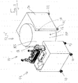
- Figure 1A shows the rotary device 12' and the filling device 14 in the uncoupled state and figures 1C and 2 show the rotary device 12' and the filling device 14 in the coupled state.
- the rotary device 12' has a cantilevering part 52 which protrudes from the support frame 20 over a horizontal distance 49 (indicated in fig.2 ).
- a cover plate 61 is provided which covers the actual rotary conveyor, as will be discussed below.
- the filling device 14 has a plurality of filling nozzle assemblies 60.
- Each nozzle assembly 60 may comprise multiple nozzles.
- the filling device comprises twenty nozzle assemblies 60 for simultaneously filling a group of cartridges positioned in the filling area 32 in the rotary device.
- the nozzle assemblies 60 are arranged along a part of a circle in order to match with a shape of the filling area 32.
- the cantilevering part 52 of the rotary device is located in the filling area 32 when the filing device 14 is docked in the docking station.
- the filling device 14 comprises a nozzle actuator 62 for moving the filling nozzle assemblies downwards and into upwardly oriented filling openings of the cartridges
- the filling device 14 comprises a further actuator 63 for moving the nozzles of each nozzle assembly relative to one another, in particular in a horizontal direction away from one another and toward one another.
- the filling device 14 is a modular device and is constructed to be undocked from the docking station and to be replaced by another filling device.
- the nozzle assemblies 60 of each filling device are mounted on an overhead beam 64 which defines an open space 65 underneath it.
- the filling area 32 is situated in said open space underneath the overhead beam 64.
- the overhead beam 64 is supported by at least a left post 65A at one end 66A of the overhead beam and by a right post 65B at an opposite end 66B of the overhead beam, the open space being situated between the posts, and wherein the filling area 32 is positioned between the left and right posts when the filling device is in the docking station.
- Each filling device comprises a reservoir 68 which is connected to the nozzle assemblies 60 via a pump 70 and a number of conduits.
- the filling station 10 comprises a common pump, and each filling device 14 comprises a pump coupling for coupling the filling device to the common pump.
- the conveyor device in the form of the rotary device 12' comprises a rotary conveyor 30 which is configured for conveying the cartridges as a group from an entry location 31 to a filling area 32, and from the filling area 32 to an exit location 33.
- the transport of the cartridges takes place in the direction of arrow 34.
- the cartridges are rotated about a main axis 36, which is vertical.
- the entry location 31, and the exit location 33 are located substantially opposite to the filling area 32.
- the entry location 31 and the exit location 33 are situated at an angle of less than 45 degrees from one another.
- the rotary device further comprises an upstream transport device 38 and a downstream transport device 39.
- the upstream transport device 38 receives the cartridges from a part of the filling line further upstream at an upstream handover location 40 and transports the cartridges to the entry location 31 where the cartridges are transferred to the rotary conveyor 30.
- the downstream transport device 39 receives the cartridges at the exit location 33 and transports the cartridges to the edge of the rotary device where a downstream handover location 41 is provided for handover to a further part of the filling line.
- the upstream transport device 38 and downstream transport device 39 each comprise three, respectively four rotating members 44 which rotate in the directions indicated by the arrows.
- Each rotating member 44 comprises recesses 45 along the outer circumference for holding the cartridges.
- the wall of each recess 45 is referred to as an urging member, because it urges the cartridge along during transport.
- a stationary guide is provided which is configured to prevent the cartridges from falling out of the recesses.
- the cartridges are filled in the filling area 32 and the filling area comprises multiple cartridge positions 50 which in top view are arranged along a part of a circle. There are twenty cartridge positions of which six are indicated with reference numeral 50.
- the rotary conveyor 30 comprises three rotary segments 55, individually indicated as 55A, 55B and 55C.
- Each rotary segment has a shape similar to a pizza slice. Each rotary segment rotates about the main axis 36. Each rotary segment comprises a plurality of cartridge holders 56 for holding a cartridge. The number of cartridge holders corresponds to the number of filling locations. Each rotary segment 55 comprises a frame or arm 57 extending from the main axis to the cartridge holders and supporting the cartridge holders and a bearing 58 via which the rotary segment 55 is connected to the main axis. A drive is also provided for driving the rotary segments, as will be discussed further below.
- Figure 4 is essentially the same figure as figure 3 except that the rotary segments 55 are in a different position.
- Rotary segment 55A is moving from the entry location 31 to the filling area 32
- rotary segment 55B is moving from the filling location 32 to the exit location 33
- rotary segment 55C is at the exit location 33 and about to be refilled in the entry location 31.
- the cartridge holders of the rotary segments follow a circular trajectory 54.
- the cartridge holders are recesses.
- a circular guide 59 extends around this circular trajectory to keep the cartridges in the cartridge holders.
- the cantilevering part comprises a part of the circular trajectory and a part of the circular guide 59.
- FIG 5 a diagram of the rotary movement of the rotary segment 55 is provided.
- the rotary segment In section I, the rotary segment is in the filling area 32 and is stationary. The cartridges are being filled.
- the rotary segment moves from the filling area 32 to the exit location 33.
- the rotary segment In section III, the rotary segment first unloads the cartridges at the exit location 33 and subsequently is reloaded with cartridges at the entry location. During unloading and loading, the rotary segment slowly rotates.
- section IV the rotary segment moves from the entry location to the filling area.
- the rotary device 12' comprises a drive system 69 for rotating the rotary segments about the main axis from the entry location to the filling area and from the filling area to the exit location, wherein the drive system is configured to stop the rotary segments at the filling area during the filling and to slowly rotate the rotary segments at the exit and entry locations.
- the rotary segments 55 are driven by a common drive 75 which is schematically indicated with reference numeral 75 in figure 6B and which is coupled to shaft 74, also schematically indicated with dashed lines.
- the drive 75 may be electric.
- the shaft 74 is coupled to a main gear 76 via intermediate gears 77, 78, 80 and intermediate shaft 79.
- the main gear 76 rotates about a central axis 36 which is the same axis as the axis around which the rotary segments rotate.
- the drive system further comprises a rotating annular cam track 82 which rotates about the main axis.
- the main gear 76 and the rotating annular cam track 82 rotate in direction 34.
- the drive system further comprises three cam devices, more in particular planetary cam devices 84A, 84B and 84C (generally indicated with 84).
- the planetary cam device 84C is behind planetary cam device 84B in figure 6B .
- Each planetary cam device 84 comprises a rotary cam 88 mounted on a shaft 89.
- Each rotary cam 88 comprises six cams 87.
- a first cam gear 90 is also mounted on the shaft 89 and a second cam gear 91 is mounted on a vertical planetary shaft 92.
- the vertical planetary shafts 92 are each connected to a planetary gear 94A, 94B, 94C (generally indicated as 94).
- the planetary gears 94A, 94B, 94C engage rotary segment gears 95A, 95B and 95C (generally indicated as 95).
- the rotary segment gears 95 are coaxial but mounted on separate coaxial shafts 96A, 96B and 96C.
- Each coaxial shaft 96 is connected to a respective rotary segment 55.
- the rotary cams 88 engage the top face 83 of the part containing the cam track 82.
- the drive 75 rotates the main gear 76 in a continuous motion via the transmission.
- the cam track 82 has a predetermined shape in order to ensures that the rotary cams 88 rotate or remain stationary according to the predetermined movement as indicated in figure 5 . This movement is relayed to the rotary segments 55 via the planetary shafts 92, the planetary gears 94.
- the rotary cams 88 are positioned at an angle of 120 degrees with respect to each other. The movement of the rotary segments 55 is therefore shifted 120 degrees in time with respect to each other.
- Each rotary segment 55 is associated with a respective cam device 84.
- the rotating annular cam track 82 drives the respective planetary cam devices 84, and each cam planetary cam device 84 in turn drives an associated rotary segment 55.
- the rotary device 12' comprises an upstream weight measuring device 100 positioned upstream of the entry location 31 along the cartridge trajectory at an upstream measurement location 101.
- the rotary device 12' further comprises a downstream weight measuring device 102 positioned downstream of the exit location 33 along the cartridge trajectory at a downstream measurement location 103.
- the rotary members 44 at the measurement locations 101, 103 have cartridge holders 45 (also referred to as urging members) which exert a horizontal force on a side wall of the cartridges but which do not support the cartridge vertically.
- the upstream and downstream transport devices 38, 39 have a stationary support floor 120 over which the cartridges 110 slide during transport, i.e. as the cartridges are urged along by the urging members.
- the upstream weight measuring device 100 is positioned in an opening 112 in said stationary support floor. During transport the weight of each empty cartridge is transferred from the support floor 120 to a sensor surface 114 of the upstream measuring device in order for a weight measurement to be carried out while the cartridge is being moved, wherein subsequently the weight of the cartridge is transferred from the support surface 114 back to the stationary support floor after the weight measurement.
- Fig. 9B shows the moment the cartridge is on the sensor surface
- figure 9C shows a subsequent moment in time in which the cartridge is transferred back to the support floor 120.
- the weight measuring device 100 comprises a peripheral surface 115. The weight of the cartridge 110 is transferred from the support floor 120 via the peripheral surface 115 to the sensor surface, and from the sensor surface via the peripheral surface 115 back to the support floor.
- the support floor 120, the sensor surface 114 and the peripheral surface 115 are flush.
- the downstream transport device 39 for transporting the cartridges from the exit location 33 further downstream also comprises urging members which exert a horizontal force on a side wall of the cartridges but do not support the cartridge vertically.
- the cartridges slide over the stationary floor during transport.
- the second weight measuring device 102 is similar to the first weight measuring device 100 and is positioned in a similar opening in said stationary support floor.
- the weight of each filled or incompletely filled cartridge is transferred from the stationary support floor 120 to the a sensor surface of the downstream measuring device 102 in order for a weight measurement to be carried out while the cartridge is being moved. Subsequently the weight of the cartridge is transferred back to the stationary support floor.
- the weight measuring devices 100, 102 comprise at least one strain gauge.
- the weight of each cartridge can be measured before and after filling without stopping the cartridge.
- a diameter of the rotary members 44 may be 100-150 mm, in particular 139 mm.
- the sensor surface 114 may be circular and have a diameter of 15 - 25mm, in particular 19.8mm.
- a passing cartridge may be in contact with the sensor surface 114 during a time period of 200 - 300ms, in particular 250ms.
- a full weight of the cartridge may rest on the sensor surface during a time period of 100 - 150ms, in particular 130ms.
- the filling station 10 may be used to fill a first series of cartridges with a first liquid.
- a first filling device 14 is docked in the docking station.
- the first filling device is undocked from the docking station, and a second filling device 14 is docked in the docking station.
- the second filling device has a different type of liquid in its reservoir. The filling process then resumes with the filling of a second series of cartridges with the second liquid by the second filling device.
- the movement will typically be a start-stop movement.
- a group cartridges is moved to a position underneath the filling station.
- the stop step the cartridges are filled.
- the filled cartridges are moved further downstream and a new group of cartridges is positioned underneath the filling station 14.
- FIG. 10 an embodiment without a cantilevering part is shown in a schematic manner.
- the circular trajectory 54 of the rotary device 12' does not cantilever, but extends downwards to just above the floor.
- the downward extending section 155 is convex and is covered with a cover plate 150.
- the frame 20 is closed by cover plates 150.
- the filling device 14 comprises a concave section 156 in which the convex section 155 fits and is docked.
- the filling station 10 for filling cartridges of electronic cigarettes with a liquid comprises a belt conveyor device 12" comprising an endless belt conveyor 200.
- the endless belt conveyor has a first straight section 201 and a second straight section 202, a first turn 203 and a second turn 204.
- the first straight section 201 is configured to be placed under the overhead beam of the filling device.
- This disclosure does not have a cantilevering part.
- endless belt conveyor may also be an endless chain conveyor or a conveyor having a series of interconnected elements forming an endless loop.
- the word endless belt conveyor is intended to have a broad meaning in this document and also cover a chain or in general a series of interconnected elements forming an endless loop.
- a group of cartridges is each time positioned in a straight row underneath the nozzle assemblies 60.
- the nozzle assemblies are also arranged in a straight row.
- the endless belt conveyor may also have a different shape such as a circular shape, similar to the circular shape of the rotary device of the first embodiment.
- the endless conveyor can also have a non-straight and non-circular shape, such as oval, but such a shape is less practical for most applications.
Landscapes
- Engineering & Computer Science (AREA)
- Mechanical Engineering (AREA)
- Basic Packing Technique (AREA)
Description
- The present invention relates to a filling station for cartridges of electronic cigarettes and to a method of filling cartridges of electronic cigarettes with a liquid in a filling station. Filling stations for cartridges of electronic cigarettes are known.
- Disposable electronic-cigarette cartridges are generally filled in a filling line. Generally, the cartridges contain a wad (also referred to as a non-woven). During the filling, the wad is impregnated with the liquid. The liquid may contain nicotine and/or aromas. The cartridges are generally filled by conveying the cartridges with the opening directed upward. The cartridges are conveyed to a filling station and are filled with a predetermined volume of the liquid.
- An important aspect of electronic cigarettes is that there are many different liquids which are sold in practice. The different liquids may have different aromas, different levels of nicotine content, and other additives may vary as well. A virtually infinite number of combinations can be made, and in practice cartridges with a large number of different liquids are sold.
- It is not practical or cost-efficient to have a complete filling line for each type of liquid which is sold. Therefore, the same filling line is generally used for different liquids. The filling line needs to be converted from one type of liquid to another type of liquid from time to time in order to meet the varying demand. It was recognized that existing filling lines have a substantial downtime every time the type of liquid is changed which is disadvantageous.
-
EP0579480 discloses a filling station 15 for filling ampules, see in particular elements 13,15 infigures 1 and12 and elements 127 in fig. 20.Figure 12 shows that the filling station is mounted via a beam on a central drive shaft 84. See alsocolumn 10, lines 13-23 ofEP0579480 . The idea behind this configuration is that the ampules which are conveyed by a turntable 13 make a continuous rotary motion and that the nozzles 127 rotate with the ampules during the filling. - It was found that this construction makes it very difficult to quickly exchange the filling station, because it has to be dismounted from the central drive shaft 84. This is a very cumbersome and long procedure which results in a excessive downtimes of the filling line.
-
US3164935 discloses a filling station which can be converted, see column 1, lines 46-52. The conversion itself is quite complicated and requires the filling station to be taken apart and to be assembled almost from the ground up. This is a very cumbersome and time-consuming process resulting in long downtimes of the filling line. -
EP1512632 A2 discloses a device for filling containers, in particular hard gelatin capsules, with solid, powdery, gelatinous and / or liquid products. The device comprises a device station for feeding and providing the containers to be filled, a device station for filling the individual containers with the filling material, wherein at least one of the two device stations is present as an exchangeable module. - It is an object of the present invention to provide a method and device to enable the conversion of a filling line for filling cartridges of electronic cigarettes in a relatively short time period and with relative ease from one type of liquid to another type of liquid.
- It is a further object of the present invention to obtain a better control of the filling process.
- In order to achieve at least one object, the invention provides a filling station for filling cartridges of electronic cigarettes with a liquid according to claim 1.
- The invention allows a fast conversion of a filling line from one liquid to another liquid.
- In top view the cartridge positions may be arranged along a part of a circle, and wherein in top view the filling nozzles may be arranged along a part of a same circle in order to match with the cartridge positions.
- In an embodiment, the conveyor is configured for making a start-stop movement, wherein the filling is carried out during a stop stage of the conveyor and wherein in top view the nozzles assemblies remain stationary during the filling. It will be clear that the nozzle assemblies may move up and down and that even the different nozzles of each nozzle assembly may move horizontally toward and away from one another, but that the nozzle assemblies as a whole remain stationary when seen in top view.
- In an embodiment, the nozzle assemblies of each filling device are mounted on an overhead beam which defines an open space underneath it, and wherein when the filling device is docked in the docking station the filling area is situated in said open space underneath the overhead beam. This was found to be a very reliable configuration which allows an easy conversion.
- In an embodiment, the overhead beam is supported by at least a left post at one end of the overhead beam and by a right post at an opposite end of the overhead beam, the open space being situated between the posts, and wherein the filling area is positioned between the left and right posts when the filling device is in the docking station. It was found that this configuration allows the entire filling station to have a simple setup, wherein the cartridges can be moved in a rotary manner.
- In an embodiment, the conveyor device has a cantilevering part which protrudes from the support frame over a horizontal distance and wherein the cantilevering part comprises the filling area. The cantilevering part is inserted underneath the nozzle assemblies and provides and effective conversion.
- In an embodiment, in top view the entry location and the exit location are located substantially opposite to the filling area. It was found that this enables a fluent movement.
- In an embodiment, each filling device comprises a reservoir which is connected to the nozzles via a pump and number of conduits. Because each filling device comprises its own reservoir, the conversion can be simple and fast.
- In an embodiment, the filling station comprises a common pump, and wherein each filling device comprises a pump coupling for coupling the filling device to the common pump. This embodiment may have a disadvantage of a more complicated conversion, but has less parts.
- In an embodiment, each filling device comprises wheels which allow a human operator to roll the filling device toward and away from the docking station. The wheels make the conversion easy to carry out. The docking movement of the filling device into the docking station is then a simple and substantially horizontal movement. The filling device may be rolled over the ground or over tracks.
- In an embodiment, the docking station comprises register holes or pins and wherein the docking coupling comprises mating register holes or pins for docking the filling device in the docking station in the required position. The register pins or holes ensure a correct position of the filling device relative to the conveyor device. The register pins or holes or provided on the sides of the filling device and the conveyor device. The register pins or holes may extend horizontally, allowing a horizontal docking movement.
- In an embodiment, the conveyor device comprises the rotary device and the rotary conveyor, wherein the rotary conveyor comprises:
- at least three rotary segments, wherein each rotary segment defines a plurality of cartridge holders for holding a cartridge, and
- a drive system for rotating the rotary segments about the main axis from the entry location to the filling area and from the filling area to the exit location, wherein the drive system is configured to stop the rotary segments at the filling area during the filling.
- It was found that this arrangement combines a high throughput with an effective control.
- In an embodiment, the conveyor device comprises the rotary device and the rotary conveyor and comprises a rotating annular cam track which rotates about the main axis, and a cam track drive which drives the rotating annular cam track, wherein each rotary segment is associated with a respective cam device, wherein the rotating annular cam track drives the respective cam devices, and wherein each cam device in turn drives an associated rotary segment. This embodiment advantageously achieves a simple synchronization and reliable movement of the rotary segments.
- In an embodiment, the rotary segments are stopped in the filling area during the filling and wherein the rotary segments move in the entry location and the exit location during the loading and unloading of the cartridges.
- In an embodiment, each nozzle assembly comprise a plurality of nozzles. This advantageously allows faster filling and an easier conversion to different types of cartridges.
- In an embodiment, the conveyor device comprises:
- an upstream weight measuring device positioned upstream of the entry location along the cartridge trajectory at an upstream measurement location,
- a downstream weight measuring device positioned downstream of the exit location along the cartridge trajectory at a downstream measurement location.
- The arrangement of the measuring devices allows a thorough control of the process without slowing down the filling.
- In an embodiment, the filling station comprises:
- an upstream transport device for transporting the cartridges to the entry location, wherein the upstream transport device comprises:
- ∘ urging members which exert a horizontal force on a side wall of the cartridges but do not support the cartridge vertically, and
- ∘ a stationary support floor over which the cartridges slide during transport, and wherein the first weight measuring device is positioned in an opening in said stationary support floor, wherein during transport the weight of each empty cartridge is transferred from the support floor to the upstream measuring device in order for a weight measurement to be carried out while the cartridge is being moved, wherein subsequently the weight of the cartridge is transferred back to the stationary support floor, and
- a downstream transport device for transporting the cartridges from the exit location further downstream, wherein the downstream transport device comprises
- ∘ urging members which exert a horizontal force on a side wall of the cartridges but do not support the cartridge vertically,
- ∘ a stationary support floor over which the cartridges slide during transport, and wherein the second weight measuring device is positioned in an opening in said stationary support floor, wherein during transport the weight of each empty cartridge is transferred from the stationary support floor to the downstream measuring device in order for a weight measurement to be carried out while the cartridge is being moved, wherein subsequently the weight of the cartridge is transferred back to the stationary support floor.
- The configuration allows a simple and effective method of measuring the weight of the cartridges before and after filling.
- In an embodiment, the at least one weight measuring device comprises at least one strain gauge.
- The present invention further relates to a method of filling cartridges of electronic cigarettes with a liquid in a filling station, the method comprising :
- providing a filling station according to any of the preceding claims, wherein a first filling device is docked in the docking station, and
- filling a first series of cartridges with a first liquid, and
- undocking the first filling device from the docking station, and
- docking a second filling device in the docking station, and
- filling a second series of cartridges with a second liquid with the second with the second filling device.
- The method has the same advantages as the filling station according to the invention.
- These and other aspects of the invention will be more readily appreciated as the same becomes better understood by reference to the following detailed description and considered in connection with the accompanying drawings in which like reference symbols designate like parts.
-
-
Figure 1A shows an isometric view of a filling station according to the invention in an uncoupled state. -
Figure 1B shows an isometric view of a filling station according to the invention with multiple filling devices. -
Figure 1C shows another isometric view of a filling station according to the invention. -
Figure 2 shows a top view of a filling station according to the invention. -
Figures 3 and4 show top views of a filling station according to the invention wherein the rotary conveyor is made visible. -
Figure 5 shows a diagram of an angular position of a rotary segment in time. -
Figure 6A shows an isometric view of a drive system for the rotary device. -
Figure 6B shows an isometric view from below of the drive system for the rotary device. -
Figure 7 shows a top view of the entry area and the exit area of the rotary device. -
Figure 8 shows a top view of a part of the rotary device including the mass measurement devices. -
Figures 9A ,9B and9C show isometric views of a part of the rotary device with the mass measurement device. -
Figure 10 shows a schematic isometric view of a second embodiment of the filling station. -
Figure 11 shows another schematic isometric view of the embodiment offigure 10 . -
Figure 12 shows an isometric view of a further embodiment not belonging to the present invention in an undocked state. -
Figure 13 shows an isometric view of the embodiment offig. 12 in a docked state. -
Fig. 14 shows an isometric view of the embodiment offig. 12 . - Turning to
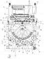
figures 1A ,1B ,1C and2 , a fillingstation 10 according to the invention is shown. The filling station is intended to form part of a filling line for filling cartridges of electronic cigarettes with a liquid. The cartridges may be disposable. - The filling station comprises a conveyor device, generally indicated as 12, in the form of a rotary device 12' and a plurality of filling
devices devices 14 are intended to be coupled to one another. To this end, the rotary device 12' comprises adocking station 16 and the fillingdevice 14 comprises adocking coupling 17. - The
docking station 16 comprises register holes 18 and thedocking coupling 17 comprises mating register pins 19 which fit in the register holes for docking the fillingdevice 14 in the required position in the docking station. The docking station further comprisesclamps 24 on the rotary device and hooks 25 on the filling device for securing the filling device to the rotary device. The docking station further comprises a mating stop surface in the form of aridge 26 on the rotary device which abuts aridge 27 on the filling device. Theridge 26 and themating stop surface 27 are provided on the side of the docking station and the filling device and allow substantially horizontal docking movement. - The rotary device 12' comprises a
first support frame 20 and the fillingdevice 14 comprises asecond support frame 21. Thefirst support frame 20 rests onpads 22 and thesecond support frame 21 rests onwheels 23. Thewheels 23 allow a human operator to roll the fillingdevice 14 toward and away from the docking station of the rotary device 12'. - The support frames 20, 21 have a same or similar height of about 1 meter, but a different height is possible.
-
Figure 1A shows the rotary device 12' and the fillingdevice 14 in the uncoupled state andfigures 1C and2 show the rotary device 12' and the fillingdevice 14 in the coupled state. - The rotary device 12' has a cantilevering part 52 which protrudes from the
support frame 20 over a horizontal distance 49 (indicated infig.2 ). A cover plate 61 is provided which covers the actual rotary conveyor, as will be discussed below. - Turning in particular to
figure 1C , the fillingdevice 14 has a plurality of fillingnozzle assemblies 60. Eachnozzle assembly 60 may comprise multiple nozzles. The filling device comprises twentynozzle assemblies 60 for simultaneously filling a group of cartridges positioned in the fillingarea 32 in the rotary device. In top view thenozzle assemblies 60 are arranged along a part of a circle in order to match with a shape of the fillingarea 32. The cantilevering part 52 of the rotary device is located in the fillingarea 32 when thefiling device 14 is docked in the docking station. - The filling
device 14 comprises a nozzle actuator 62 for moving the filling nozzle assemblies downwards and into upwardly oriented filling openings of the cartridges The fillingdevice 14 comprises a further actuator 63 for moving the nozzles of each nozzle assembly relative to one another, in particular in a horizontal direction away from one another and toward one another. - The filling
device 14 is a modular device and is constructed to be undocked from the docking station and to be replaced by another filling device. - The
nozzle assemblies 60 of each filling device are mounted on an overhead beam 64 which defines anopen space 65 underneath it. When the fillingdevice 60 is docked in the docking station, the fillingarea 32 is situated in said open space underneath the overhead beam 64. - The overhead beam 64 is supported by at least a
left post 65A at one end 66A of the overhead beam and by aright post 65B at an opposite end 66B of the overhead beam, the open space being situated between the posts, and wherein the fillingarea 32 is positioned between the left and right posts when the filling device is in the docking station. - Each filling device comprises a
reservoir 68 which is connected to thenozzle assemblies 60 via apump 70 and a number of conduits. - In an alternative embodiment, the filling
station 10 comprises a common pump, and each fillingdevice 14 comprises a pump coupling for coupling the filling device to the common pump. - Turning to
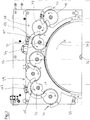
figures 3 and4 , the conveyor device in the form of the rotary device 12' comprises arotary conveyor 30 which is configured for conveying the cartridges as a group from anentry location 31 to a fillingarea 32, and from the fillingarea 32 to anexit location 33. The transport of the cartridges takes place in the direction ofarrow 34. The cartridges are rotated about amain axis 36, which is vertical. - In top view, the
entry location 31, and theexit location 33 are located substantially opposite to the fillingarea 32. Theentry location 31 and theexit location 33 are situated at an angle of less than 45 degrees from one another. - The rotary device further comprises an
upstream transport device 38 and adownstream transport device 39. Theupstream transport device 38 receives the cartridges from a part of the filling line further upstream at an upstream handover location 40 and transports the cartridges to theentry location 31 where the cartridges are transferred to therotary conveyor 30. Thedownstream transport device 39 receives the cartridges at theexit location 33 and transports the cartridges to the edge of the rotary device where adownstream handover location 41 is provided for handover to a further part of the filling line. - The
upstream transport device 38 anddownstream transport device 39 each comprise three, respectively fourrotating members 44 which rotate in the directions indicated by the arrows. Each rotatingmember 44 comprisesrecesses 45 along the outer circumference for holding the cartridges. The wall of eachrecess 45 is referred to as an urging member, because it urges the cartridge along during transport. - Around each rotating
member 44, a stationary guide is provided which is configured to prevent the cartridges from falling out of the recesses. - The cartridges are filled in the filling
area 32 and the filling area comprisesmultiple cartridge positions 50 which in top view are arranged along a part of a circle. There are twenty cartridge positions of which six are indicated withreference numeral 50. - The
rotary conveyor 30 comprises threerotary segments 55, individually indicated as 55A, 55B and 55C. - Each rotary segment has a shape similar to a pizza slice. Each rotary segment rotates about the
main axis 36. Each rotary segment comprises a plurality of cartridge holders 56 for holding a cartridge. The number of cartridge holders corresponds to the number of filling locations. Eachrotary segment 55 comprises a frame orarm 57 extending from the main axis to the cartridge holders and supporting the cartridge holders and abearing 58 via which therotary segment 55 is connected to the main axis. A drive is also provided for driving the rotary segments, as will be discussed further below. - In
figure 3 the rotary segment 55Bhas its cartridge holders positioned in the fillingarea 32. -
Figure 4 is essentially the same figure asfigure 3 except that therotary segments 55 are in a different position.Rotary segment 55A is moving from theentry location 31 to the fillingarea 32, rotary segment 55B is moving from the fillinglocation 32 to theexit location 33 androtary segment 55C is at theexit location 33 and about to be refilled in theentry location 31. - The cartridge holders of the rotary segments follow a
circular trajectory 54. The cartridge holders are recesses. A circular guide 59 (seefig. 1B ) extends around this circular trajectory to keep the cartridges in the cartridge holders. The cantilevering part comprises a part of the circular trajectory and a part of thecircular guide 59. - Turning to
figure 5 , a diagram of the rotary movement of therotary segment 55 is provided. In section I, the rotary segment is in the fillingarea 32 and is stationary. The cartridges are being filled. In section II the rotary segment moves from the fillingarea 32 to theexit location 33. In section III, the rotary segment first unloads the cartridges at theexit location 33 and subsequently is reloaded with cartridges at the entry location. During unloading and loading, the rotary segment slowly rotates. In section IV, the rotary segment moves from the entry location to the filling area. - Turning to
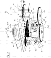
figures 6A and6B , the rotary device 12' comprises a drive system 69 for rotating the rotary segments about the main axis from the entry location to the filling area and from the filling area to the exit location, wherein the drive system is configured to stop the rotary segments at the filling area during the filling and to slowly rotate the rotary segments at the exit and entry locations. - The
rotary segments 55 are driven by a common drive 75 which is schematically indicated with reference numeral 75 infigure 6B and which is coupled toshaft 74, also schematically indicated with dashed lines. The drive 75 may be electric. Theshaft 74 is coupled to amain gear 76 viaintermediate gears intermediate shaft 79. Themain gear 76 rotates about acentral axis 36 which is the same axis as the axis around which the rotary segments rotate. - The drive system further comprises a rotating annular cam track 82 which rotates about the main axis. The
main gear 76 and the rotating annular cam track 82 rotate indirection 34. The drive system further comprises three cam devices, more in particularplanetary cam devices 84A, 84B and 84C (generally indicated with 84). The planetary cam device 84C is behind planetary cam device 84B infigure 6B . - Each planetary cam device 84 comprises a
rotary cam 88 mounted on ashaft 89. Eachrotary cam 88 comprises six cams 87. Afirst cam gear 90 is also mounted on theshaft 89 and a second cam gear 91 is mounted on a verticalplanetary shaft 92. The verticalplanetary shafts 92 are each connected to a planetary gear 94A, 94B, 94C (generally indicated as 94). The planetary gears 94A, 94B, 94C engage rotary segment gears 95A, 95B and 95C (generally indicated as 95). The rotary segment gears 95 are coaxial but mounted on separatecoaxial shafts respective rotary segment 55. - In an embodiment the
rotary cams 88 engage thetop face 83 of the part containing the cam track 82. - The drive 75 rotates the
main gear 76 in a continuous motion via the transmission. The cam track 82 has a predetermined shape in order to ensures that therotary cams 88 rotate or remain stationary according to the predetermined movement as indicated infigure 5 . This movement is relayed to therotary segments 55 via theplanetary shafts 92, the planetary gears 94. - In top view, the
rotary cams 88 are positioned at an angle of 120 degrees with respect to each other. The movement of therotary segments 55 is therefore shifted 120 degrees in time with respect to each other. - Each
rotary segment 55 is associated with a respective cam device 84. The rotating annular cam track 82 drives the respective planetary cam devices 84, and each cam planetary cam device 84 in turn drives an associatedrotary segment 55. - Turning to
figures 7 and8 , the rotary device 12' comprises an upstreamweight measuring device 100 positioned upstream of theentry location 31 along the cartridge trajectory at anupstream measurement location 101. The rotary device 12' further comprises a downstream weight measuring device 102 positioned downstream of theexit location 33 along the cartridge trajectory at adownstream measurement location 103. - The
rotary members 44 at themeasurement locations - The upstream and
downstream transport devices stationary support floor 120 over which thecartridges 110 slide during transport, i.e. as the cartridges are urged along by the urging members. - The upstream
weight measuring device 100 is positioned in an opening 112 in said stationary support floor. During transport the weight of each empty cartridge is transferred from thesupport floor 120 to asensor surface 114 of the upstream measuring device in order for a weight measurement to be carried out while the cartridge is being moved, wherein subsequently the weight of the cartridge is transferred from thesupport surface 114 back to the stationary support floor after the weight measurement.Fig. 9B shows the moment the cartridge is on the sensor surface andfigure 9C shows a subsequent moment in time in which the cartridge is transferred back to thesupport floor 120. Theweight measuring device 100 comprises a peripheral surface 115. The weight of thecartridge 110 is transferred from thesupport floor 120 via the peripheral surface 115 to the sensor surface, and from the sensor surface via the peripheral surface 115 back to the support floor. Thesupport floor 120, thesensor surface 114 and the peripheral surface 115 are flush. - The
downstream transport device 39 for transporting the cartridges from theexit location 33 further downstream also comprises urging members which exert a horizontal force on a side wall of the cartridges but do not support the cartridge vertically. - The cartridges slide over the stationary floor during transport. The second weight measuring device 102 is similar to the first
weight measuring device 100 and is positioned in a similar opening in said stationary support floor. During transport, the weight of each filled or incompletely filled cartridge is transferred from thestationary support floor 120 to the a sensor surface of the downstream measuring device 102 in order for a weight measurement to be carried out while the cartridge is being moved. Subsequently the weight of the cartridge is transferred back to the stationary support floor. Theweight measuring devices 100, 102 comprise at least one strain gauge. - With the weight measuring devices, the weight of each cartridge can be measured before and after filling without stopping the cartridge.
- A diameter of the
rotary members 44 may be 100-150 mm, in particular 139 mm. Thesensor surface 114 may be circular and have a diameter of 15 - 25mm, in particular 19.8mm. A passing cartridge may be in contact with thesensor surface 114 during a time period of 200 - 300ms, in particular 250ms. A full weight of the cartridge may rest on the sensor surface during a time period of 100 - 150ms, in particular 130ms. - In use the filling
station 10 may be used to fill a first series of cartridges with a first liquid. Afirst filling device 14 is docked in the docking station. When the filing line needs to be converted to a different type of liquid, the first filling device is undocked from the docking station, and asecond filling device 14 is docked in the docking station. The second filling device has a different type of liquid in its reservoir. The filling process then resumes with the filling of a second series of cartridges with the second liquid by the second filling device. - The movement will typically be a start-stop movement. In the move step a group cartridges is moved to a position underneath the filling station. In the stop step the cartridges are filled. In a next move step the filled cartridges are moved further downstream and a new group of cartridges is positioned underneath the filling
station 14. - Turning to
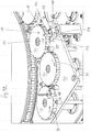
figures 10 and11 , an embodiment without a cantilevering part is shown in a schematic manner. Thecircular trajectory 54 of the rotary device 12' does not cantilever, but extends downwards to just above the floor. The downward extending section 155 is convex and is covered with acover plate 150. Theframe 20 is closed bycover plates 150. - The filling
device 14 comprises a concave section 156 in which the convex section 155 fits and is docked. - Turning to
figures 12-14 , in a further embodiment not belonging to the present invention, the fillingstation 10 for filling cartridges of electronic cigarettes with a liquid comprises abelt conveyor device 12" comprising anendless belt conveyor 200. The endless belt conveyor has a firststraight section 201 and a second straight section 202, afirst turn 203 and asecond turn 204. The firststraight section 201 is configured to be placed under the overhead beam of the filling device. - This disclosure does not have a cantilevering part.
- It will be understood that the endless belt conveyor may also be an endless chain conveyor or a conveyor having a series of interconnected elements forming an endless loop. The word endless belt conveyor is intended to have a broad meaning in this document and also cover a chain or in general a series of interconnected elements forming an endless loop.
- In operation, a group of cartridges is each time positioned in a straight row underneath the
nozzle assemblies 60. The nozzle assemblies are also arranged in a straight row. - It will be understood that the endless belt conveyor may also have a different shape such as a circular shape, similar to the circular shape of the rotary device of the first embodiment. The endless conveyor can also have a non-straight and non-circular shape, such as oval, but such a shape is less practical for most applications.
- It will be recognized that an embodiment may not achieve all of the stated objects.
- As required, detailed embodiments of the present invention are disclosed herein; however, it is to be understood that the disclosed embodiments are merely exemplary of the invention, which can be embodied in various forms. Therefore, specific structural and functional details disclosed herein are not to be interpreted as limiting, but merely as a basis for the claims and as a representative basis for teaching one skilled in the art to variously employ the present invention in virtually any appropriately detailed structure. Further, the terms and phrases used herein are not intended to be limiting, but rather, to provide an understandable description of the invention.
- The terms "a" or "an", as used herein, are defined as one or more than one. The term plurality, as used herein, is defined as two or more than two. The term another, as used herein, is defined as at least a second or more. The terms including and/or having, as used herein, are defined as comprising (i.e., open language, not excluding other elements or steps). Any reference signs in the claims should not be construed as limiting the scope of the claims or the invention.
- The mere fact that certain measures are recited in mutually different dependent claims does not indicate that a combination of these measures cannot be used to advantage.
Claims (15)
- Filling station (10) for filling cartridges of electronic cigarettes with a liquid, the filling station comprising:- a rotary conveyor device (12'), the conveyor device comprising:∘ a support frame (20),∘ a rotary conveyor (30) constructed for rotating the cartridges around a main axis (36),∘ an entry location (31) where the cartridges enter the conveyor,∘ a filling area (32) where the cartridges are filled, wherein the filling area comprises multiple cartridge positions (50),∘ an exit location (33) where the cartridges exit the conveyor,∘ a docking station (16) into which a filling device (14) can be docked,wherein the rotary conveyor further comprises:∘ at least three rotary segments (55A, 55B, 55C), wherein each rotary segment defines a plurality of cartridge holders (56) for holding a cartridge, and∘ a drive system (69) for rotating the rotary segments about the main axis from the entry location to the filling area and from the filling area to the exit location, wherein the drive system (69) is configured to stop the rotary segments at the filling area (32) during the filling,wherein the rotary segments are suitable for stopping in the filling area during the filling and wherein the rotary segments are moveable in the entry location and the exit location during the loading and unloading of the cartridges,- a plurality of filling devices (14), each filling device comprising:wherein each filling device is constructed to be undocked from the docking station and to be replaced by another filling device.∘ a support frame (21),∘ at least one docking coupling (17) for docking the filling device in the docking station,∘ a plurality of filling nozzles assemblies (60) for simultaneously filling a group of cartridges positioned in the filling area in the conveyor device, wherein in top view the filling nozzles are arranged according to the shape of the filling area,∘ a nozzle actuator (62) for moving the filling nozzles downwards and into upwardly oriented filling openings of the cartridges,
- Filling station according to claim 1, wherein in top view the cartridge positions are arranged along a part of a circle, and wherein in top view the filling nozzles are arranged along a part of a same circle in order to match with the cartridge positions.
- Filling station according to claim 1 or 2, wherein the conveyor is configured for making a start-stop movement, wherein the filling is carried out during a stop stage of the conveyor and wherein in top view the nozzles assemblies (60) remain stationary during the filling.
- Filling station according to any of the preceding claims, wherein the nozzle assemblies (60) of each filling device are mounted on an overhead beam (64) which defines an open space (65) underneath it, and wherein when the filling device is docked in the docking station the filling area (32) is situated in said open space underneath the overhead beam.
- Filling station according to claim 4, wherein the overhead beam is supported by at least a left post (65A) at one end (66A) of the overhead beam and by a right post (65B) at an opposite end (66B) of the overhead beam, the open space being situated between the posts, and wherein the filling area (32) is positioned between the left and right posts when the filling device is in the docking station.
- Filling station according to any of the preceding claims, comprising the rotary device, wherein the rotary device has a cantilevering part (52) which protrudes from the support frame over a horizontal distance (49), wherein the cantilevering part comprises a part of a circular trajectory (54) followed by the rotary conveyor (30), including the filling area (32) where the cartridges are filled.
- Filling station according to any of the preceding claims, wherein in top view the entry location (31) and the exit location (33) are located substantially opposite to the filling area (32).
- Filling station according to any of the preceding claims, wherein each filling device comprises a reservoir (68) which is connected to the nozzles via a pump (70) and a number of conduits.
- Filling station according to any of the preceding claims, wherein the rotary device comprises a rotating annular cam track (82) rotatable about the main axis (36), and a cam track drive (75) for driving the rotating annular cam track (82), wherein each rotary segment (55A, 55B, 55C) is associated with a respective cam device (84A, 84B, 84C), wherein the rotating annular cam track can drive the respective cam devices, and wherein each cam device in turn can drive an associated rotary segment.
- Filling station according to claim 9, wherein each cam device comprises a rotary cam (88) for engaging a top face of the annular cam track (82).
- Filling station according to any of the preceding claims, wherein the conveyor device comprises:- an upstream weight measuring device (100) positioned upstream of the entry location along the cartridge trajectory at an upstream measurement location (101),- a downstream weight measuring device (102) positioned downstream of the exit location along the cartridge trajectory at a downstream measurement location (103).
- Filling station according to claim 11, wherein the conveyor device comprises:- an upstream transport device (38) for transporting the cartridges (110) to the entry location (31), wherein the upstream transport device comprises:∘ cartridge holders (45) capable of exerting a horizontal force on a side wall (111) of the cartridges but are not suited for supporting the cartridge vertically, and∘ a stationary support floor (120) over which the cartridges can slide during transport, and wherein the first weight measuring device (100) can be positioned in an opening (112) in said stationary support floor, wherein during transport the weight of each empty cartridge can be transferred from the support floor to a sensor surface (114) of the upstream measuring device in order for a weight measurement to be carried out while the cartridge is being moved, wherein subsequently the weight of the cartridge can be transferred back to the stationary support floor, and- a downstream transport device (39) for transporting the cartridges from the exit location (33) further downstream, wherein the downstream transport device comprises:∘ cartridge holders (45) for exerting a horizontal force on a side wall (111) of the cartridges but are not suited for supporting the cartridge vertically,∘ a stationary support floor (120) over which the cartridges can slide during transport, and wherein the second weight measuring device (102) is positioned in an opening (112) in said stationary support floor, wherein during transport the weight of each empty cartridge can be transferred from the stationary support floor to a sensor surface of the downstream measuring device in order for a weight measurement to be carried out while the cartridge is being moved, wherein subsequently the weight of the cartridge can be transferred back to the stationary support floor.
- Filling station according to any of the preceding claims except claim 6, wherein the conveyor device does not have a cantilevering part, and wherein in particular the circular trajectory (54) forms an upper part of a convex section (155) which extends from the circular trajectory (54) downwards to the ground or to just above the ground.
- Method of filling cartridges of electronic cigarettes with a liquid in a filling station (10), the method comprising:- providing a filling station (10) according to any of the preceding claims, wherein a first filling device (14) is docked in the docking station, and- filling a first series of cartridges with a first liquid, and- undocking the first filling device from the docking station, and- docking a second filling device (14) in the docking station, and- filling a second series of cartridges with a second liquid with the second filling device.
- Method according to claim 14, wherein the cartridges are moved by the conveyor (30) of the conveyor device (12), and wherein said movement is a start stop movement wherein in a moving step each time a group of cartridges is moved underneath the filling station by the conveyor device, and wherein during a stop step the cartridges of the group are filled by the filling device (14).
Priority Applications (1)
| Application Number | Priority Date | Filing Date | Title |
|---|---|---|---|
| PL16742032T PL3307637T3 (en) | 2015-06-09 | 2016-06-09 | Filling station and method for filling cartridges of electronic cigarettes |
Applications Claiming Priority (2)
| Application Number | Priority Date | Filing Date | Title |
|---|---|---|---|
| NL2014945 | 2015-06-09 | ||
| PCT/NL2016/050414 WO2016200259A1 (en) | 2015-06-09 | 2016-06-09 | Filling station for filling cartridges of electronic cigarettes |
Publications (2)
| Publication Number | Publication Date |
|---|---|
| EP3307637A1 EP3307637A1 (en) | 2018-04-18 |
| EP3307637B1 true EP3307637B1 (en) | 2020-02-26 |
Family
ID=53783856
Family Applications (1)
| Application Number | Title | Priority Date | Filing Date |
|---|---|---|---|
| EP16742032.2A Active EP3307637B1 (en) | 2015-06-09 | 2016-06-09 | Filling station and method for filling cartridges of electronic cigarettes |
Country Status (4)
| Country | Link |
|---|---|
| EP (1) | EP3307637B1 (en) |
| ES (1) | ES2791978T3 (en) |
| PL (1) | PL3307637T3 (en) |
| WO (1) | WO2016200259A1 (en) |
Families Citing this family (26)
| Publication number | Priority date | Publication date | Assignee | Title |
|---|---|---|---|---|
| US10244793B2 (en) | 2005-07-19 | 2019-04-02 | Juul Labs, Inc. | Devices for vaporization of a substance |
| US10279934B2 (en) | 2013-03-15 | 2019-05-07 | Juul Labs, Inc. | Fillable vaporizer cartridge and method of filling |
| US10076139B2 (en) | 2013-12-23 | 2018-09-18 | Juul Labs, Inc. | Vaporizer apparatus |
| US10159282B2 (en) | 2013-12-23 | 2018-12-25 | Juul Labs, Inc. | Cartridge for use with a vaporizer device |
| USD825102S1 (en) | 2016-07-28 | 2018-08-07 | Juul Labs, Inc. | Vaporizer device with cartridge |
| US10058129B2 (en) | 2013-12-23 | 2018-08-28 | Juul Labs, Inc. | Vaporization device systems and methods |
| HRP20211514T1 (en) | 2013-12-23 | 2021-12-24 | Juul Labs International Inc. | Vaporization device systems |
| US20160366947A1 (en) | 2013-12-23 | 2016-12-22 | James Monsees | Vaporizer apparatus |
| USD842536S1 (en) | 2016-07-28 | 2019-03-05 | Juul Labs, Inc. | Vaporizer cartridge |
| JP6802792B2 (en) | 2014-12-05 | 2020-12-23 | ジュール・ラブズ・インコーポレイテッドJuul Labs, Inc. | Adjusted dose control |
| SG10202108578XA (en) | 2016-02-11 | 2021-09-29 | Juul Labs Inc | Securely attaching cartridges for vaporizer devices |
| US10405582B2 (en) | 2016-03-10 | 2019-09-10 | Pax Labs, Inc. | Vaporization device with lip sensing |
| USD849996S1 (en) | 2016-06-16 | 2019-05-28 | Pax Labs, Inc. | Vaporizer cartridge |
| USD836541S1 (en) | 2016-06-23 | 2018-12-25 | Pax Labs, Inc. | Charging device |
| USD851830S1 (en) | 2016-06-23 | 2019-06-18 | Pax Labs, Inc. | Combined vaporizer tamp and pick tool |
| CN110191649B (en) | 2016-12-12 | 2022-06-14 | Vmr产品有限责任公司 | Evaporator material box |
| IT201700072715A1 (en) | 2017-06-29 | 2018-12-29 | Gd Spa | System for assembling and filling electronic cigarettes |
| USD887632S1 (en) | 2017-09-14 | 2020-06-16 | Pax Labs, Inc. | Vaporizer cartridge |
| IT201700123930A1 (en) * | 2017-10-31 | 2019-05-01 | Ima Spa | Filling machine. |
| WO2019106503A1 (en) * | 2017-12-01 | 2019-06-06 | G.D | Station and method for welding parts of electronic cigarettes |
| PL3717363T3 (en) * | 2017-12-01 | 2021-12-20 | G.D S.P.A. | Station and method for filling cartridges of electronic cigarettes |
| IT201800002628A1 (en) * | 2018-02-13 | 2019-08-13 | Gd Spa | Machine and method for filling cartridges for aerosol generators. |
| IT201800005756A1 (en) | 2018-05-28 | 2019-11-28 | MACHINE AND PROCEDURE FOR AUTOMATICALLY TREATING COMPONENTS OF INHALERS, IN PARTICULAR CARTOMISERS FOR ELECTRONIC CIGARETTES. | |
| US20210161216A1 (en) * | 2018-07-19 | 2021-06-03 | Sluis Cigar Machinery B.V. | System for filling device parts of simulated smoking devices |
| CN113365519A (en) * | 2019-01-21 | 2021-09-07 | 吉第联合股份公司 | Machine and method for producing electronic cigarette cartridges |
| CN113967712B (en) * | 2021-11-02 | 2024-06-21 | 芜湖永辉汽车紧固件有限公司 | Full-automatic nut production line and production equipment thereof |
Citations (2)
| Publication number | Priority date | Publication date | Assignee | Title |
|---|---|---|---|---|
| US8455773B2 (en) * | 2007-09-24 | 2013-06-04 | Ima Life S.R.L. | Apparatus and method for weighing containers |
| WO2014195447A1 (en) * | 2013-06-07 | 2014-12-11 | Bausch + Ströbel Maschinenfabrik Ilshofen GmbH + Co. KG | Transfer apparatus |
Family Cites Families (5)
| Publication number | Priority date | Publication date | Assignee | Title |
|---|---|---|---|---|
| US3164935A (en) | 1957-06-22 | 1965-01-12 | Crompton & Knowles Corp | Strip packaging machines |
| TW252081B (en) | 1992-07-14 | 1995-07-21 | Eizai Co Ltd | |
| US6761191B2 (en) * | 2000-11-03 | 2004-07-13 | Robert A. Rosen | Liquid filling system with improved fluid displacement, nozzle and container handling, cleaning, and calibration/set-up capabilities |
| DE20313807U1 (en) * | 2003-09-03 | 2003-11-06 | Harro Höfliger Verpackungsmaschinen GmbH, 71573 Allmersbach | Device for filling containers, such as hard gelatin capsules in particular |
| IT1392277B1 (en) * | 2008-12-18 | 2012-02-24 | Ima Spa | MACHINE AND METHOD TO FILL AND CHECK CAPSULES |
-
2016
- 2016-06-09 ES ES16742032T patent/ES2791978T3/en active Active
- 2016-06-09 EP EP16742032.2A patent/EP3307637B1/en active Active
- 2016-06-09 WO PCT/NL2016/050414 patent/WO2016200259A1/en unknown
- 2016-06-09 PL PL16742032T patent/PL3307637T3/en unknown
Patent Citations (2)
| Publication number | Priority date | Publication date | Assignee | Title |
|---|---|---|---|---|
| US8455773B2 (en) * | 2007-09-24 | 2013-06-04 | Ima Life S.R.L. | Apparatus and method for weighing containers |
| WO2014195447A1 (en) * | 2013-06-07 | 2014-12-11 | Bausch + Ströbel Maschinenfabrik Ilshofen GmbH + Co. KG | Transfer apparatus |
Also Published As
| Publication number | Publication date |
|---|---|
| EP3307637A1 (en) | 2018-04-18 |
| ES2791978T3 (en) | 2020-11-06 |
| PL3307637T3 (en) | 2020-11-16 |
| WO2016200259A1 (en) | 2016-12-15 |
Similar Documents
| Publication | Publication Date | Title |
|---|---|---|
| EP3307637B1 (en) | Filling station and method for filling cartridges of electronic cigarettes | |
| CN104144857B (en) | kit | |
| US7562791B2 (en) | Tablet filling device | |
| CN103221177B (en) | Taper roller feedway, taper roll bearing apparatus for assembling and taper roller supply method | |
| US7395944B2 (en) | Medicine supply apparatus | |
| CN101848838B (en) | Apparatus and method for weighing containers | |
| JP2008532887A (en) | Inclined roller type article conveyor belt conveyor | |
| CN104058122A (en) | Drop assistance apparatus, filler system, and filling assistance method | |
| JP6079987B2 (en) | Container supply device | |
| US9604786B2 (en) | Bread conveying apparatus and bread slicing apparatus | |
| JP2008008897A (en) | Front and back face appearance inspecting apparatus, side-face appearance inspecting apparatus and appearance inspecting apparatus of tablet | |
| DK2560882T3 (en) | Device and method for supply of eggs to a package unit | |
| KR20140107568A (en) | Method and apparatus for filling capsules with loose material and for their sealing | |
| US2764863A (en) | Capsule filling machine | |
| KR101832427B1 (en) | Tablet dispenser of drug packing apparatus | |
| US20130248546A1 (en) | Container Denester Apparatus | |
| CN213201065U (en) | Medicine dispensing device of vertical medicine dispensing machine | |
| JP2015166133A (en) | printer | |
| US7000368B2 (en) | Method for sealing capsules and apparatus to perform said method | |
| CN112079033A (en) | Medicine discharging device of vertical automatic medicine dispensing machine | |
| CN215477653U (en) | Circulation holds in palm material device and material conveyor | |
| US2925902A (en) | Conveyor systems and tray orienting means therefor | |
| CN105738639A (en) | Test-paper-strip conveying mechanism | |
| JP2006321609A (en) | Container feeding device | |
| KR20100013072U (en) | Arranging Apparatus for Receptacle |
Legal Events
| Date | Code | Title | Description |
|---|---|---|---|
| STAA | Information on the status of an ep patent application or granted ep patent |
Free format text: STATUS: THE INTERNATIONAL PUBLICATION HAS BEEN MADE |
|
| PUAI | Public reference made under article 153(3) epc to a published international application that has entered the european phase |
Free format text: ORIGINAL CODE: 0009012 |
|
| STAA | Information on the status of an ep patent application or granted ep patent |
Free format text: STATUS: REQUEST FOR EXAMINATION WAS MADE |
|
| 17P | Request for examination filed |
Effective date: 20171129 |
|
| AK | Designated contracting states |
Kind code of ref document: A1 Designated state(s): AL AT BE BG CH CY CZ DE DK EE ES FI FR GB GR HR HU IE IS IT LI LT LU LV MC MK MT NL NO PL PT RO RS SE SI SK SM TR |
|
| AX | Request for extension of the european patent |
Extension state: BA ME |
|
| DAV | Request for validation of the european patent (deleted) | ||
| DAX | Request for extension of the european patent (deleted) | ||
| TPAC | Observations filed by third parties |
Free format text: ORIGINAL CODE: EPIDOSNTIPA |
|
| STAA | Information on the status of an ep patent application or granted ep patent |
Free format text: STATUS: EXAMINATION IS IN PROGRESS |
|
| 17Q | First examination report despatched |
Effective date: 20181122 |
|
| GRAP | Despatch of communication of intention to grant a patent |
Free format text: ORIGINAL CODE: EPIDOSNIGR1 |
|
| STAA | Information on the status of an ep patent application or granted ep patent |
Free format text: STATUS: GRANT OF PATENT IS INTENDED |
|
| INTG | Intention to grant announced |
Effective date: 20190429 |
|
| GRAJ | Information related to disapproval of communication of intention to grant by the applicant or resumption of examination proceedings by the epo deleted |
Free format text: ORIGINAL CODE: EPIDOSDIGR1 |
|
| STAA | Information on the status of an ep patent application or granted ep patent |
Free format text: STATUS: EXAMINATION IS IN PROGRESS |
|
| GRAP | Despatch of communication of intention to grant a patent |
Free format text: ORIGINAL CODE: EPIDOSNIGR1 |
|
| STAA | Information on the status of an ep patent application or granted ep patent |
Free format text: STATUS: GRANT OF PATENT IS INTENDED |
|
| INTC | Intention to grant announced (deleted) | ||
| INTG | Intention to grant announced |
Effective date: 20190923 |
|
| GRAS | Grant fee paid |
Free format text: ORIGINAL CODE: EPIDOSNIGR3 |
|
| GRAA | (expected) grant |
Free format text: ORIGINAL CODE: 0009210 |
|
| STAA | Information on the status of an ep patent application or granted ep patent |
Free format text: STATUS: THE PATENT HAS BEEN GRANTED |
|
| AK | Designated contracting states |
Kind code of ref document: B1 Designated state(s): AL AT BE BG CH CY CZ DE DK EE ES FI FR GB GR HR HU IE IS IT LI LT LU LV MC MK MT NL NO PL PT RO RS SE SI SK SM TR |
|
| REG | Reference to a national code |
Ref country code: GB Ref legal event code: FG4D |
|
| REG | Reference to a national code |
Ref country code: CH Ref legal event code: EP |
|
| REG | Reference to a national code |
Ref country code: DE Ref legal event code: R096 Ref document number: 602016030594 Country of ref document: DE |
|
| REG | Reference to a national code |
Ref country code: AT Ref legal event code: REF Ref document number: 1237359 Country of ref document: AT Kind code of ref document: T Effective date: 20200315 |
|
| REG | Reference to a national code |
Ref country code: IE Ref legal event code: FG4D |
|
| REG | Reference to a national code |
Ref country code: NL Ref legal event code: FP |
|
| PG25 | Lapsed in a contracting state [announced via postgrant information from national office to epo] |
Ref country code: FI Free format text: LAPSE BECAUSE OF FAILURE TO SUBMIT A TRANSLATION OF THE DESCRIPTION OR TO PAY THE FEE WITHIN THE PRESCRIBED TIME-LIMIT Effective date: 20200226 Ref country code: RS Free format text: LAPSE BECAUSE OF FAILURE TO SUBMIT A TRANSLATION OF THE DESCRIPTION OR TO PAY THE FEE WITHIN THE PRESCRIBED TIME-LIMIT Effective date: 20200226 Ref country code: NO Free format text: LAPSE BECAUSE OF FAILURE TO SUBMIT A TRANSLATION OF THE DESCRIPTION OR TO PAY THE FEE WITHIN THE PRESCRIBED TIME-LIMIT Effective date: 20200526 |
|
| REG | Reference to a national code |
Ref country code: LT Ref legal event code: MG4D |
|
| PG25 | Lapsed in a contracting state [announced via postgrant information from national office to epo] |
Ref country code: IS Free format text: LAPSE BECAUSE OF FAILURE TO SUBMIT A TRANSLATION OF THE DESCRIPTION OR TO PAY THE FEE WITHIN THE PRESCRIBED TIME-LIMIT Effective date: 20200626 Ref country code: BG Free format text: LAPSE BECAUSE OF FAILURE TO SUBMIT A TRANSLATION OF THE DESCRIPTION OR TO PAY THE FEE WITHIN THE PRESCRIBED TIME-LIMIT Effective date: 20200526 Ref country code: SE Free format text: LAPSE BECAUSE OF FAILURE TO SUBMIT A TRANSLATION OF THE DESCRIPTION OR TO PAY THE FEE WITHIN THE PRESCRIBED TIME-LIMIT Effective date: 20200226 Ref country code: LV Free format text: LAPSE BECAUSE OF FAILURE TO SUBMIT A TRANSLATION OF THE DESCRIPTION OR TO PAY THE FEE WITHIN THE PRESCRIBED TIME-LIMIT Effective date: 20200226 Ref country code: HR Free format text: LAPSE BECAUSE OF FAILURE TO SUBMIT A TRANSLATION OF THE DESCRIPTION OR TO PAY THE FEE WITHIN THE PRESCRIBED TIME-LIMIT Effective date: 20200226 Ref country code: GR Free format text: LAPSE BECAUSE OF FAILURE TO SUBMIT A TRANSLATION OF THE DESCRIPTION OR TO PAY THE FEE WITHIN THE PRESCRIBED TIME-LIMIT Effective date: 20200527 |
|
| PG25 | Lapsed in a contracting state [announced via postgrant information from national office to epo] |
Ref country code: EE Free format text: LAPSE BECAUSE OF FAILURE TO SUBMIT A TRANSLATION OF THE DESCRIPTION OR TO PAY THE FEE WITHIN THE PRESCRIBED TIME-LIMIT Effective date: 20200226 Ref country code: SM Free format text: LAPSE BECAUSE OF FAILURE TO SUBMIT A TRANSLATION OF THE DESCRIPTION OR TO PAY THE FEE WITHIN THE PRESCRIBED TIME-LIMIT Effective date: 20200226 Ref country code: DK Free format text: LAPSE BECAUSE OF FAILURE TO SUBMIT A TRANSLATION OF THE DESCRIPTION OR TO PAY THE FEE WITHIN THE PRESCRIBED TIME-LIMIT Effective date: 20200226 Ref country code: SK Free format text: LAPSE BECAUSE OF FAILURE TO SUBMIT A TRANSLATION OF THE DESCRIPTION OR TO PAY THE FEE WITHIN THE PRESCRIBED TIME-LIMIT Effective date: 20200226 Ref country code: RO Free format text: LAPSE BECAUSE OF FAILURE TO SUBMIT A TRANSLATION OF THE DESCRIPTION OR TO PAY THE FEE WITHIN THE PRESCRIBED TIME-LIMIT Effective date: 20200226 Ref country code: LT Free format text: LAPSE BECAUSE OF FAILURE TO SUBMIT A TRANSLATION OF THE DESCRIPTION OR TO PAY THE FEE WITHIN THE PRESCRIBED TIME-LIMIT Effective date: 20200226 Ref country code: CZ Free format text: LAPSE BECAUSE OF FAILURE TO SUBMIT A TRANSLATION OF THE DESCRIPTION OR TO PAY THE FEE WITHIN THE PRESCRIBED TIME-LIMIT Effective date: 20200226 Ref country code: PT Free format text: LAPSE BECAUSE OF FAILURE TO SUBMIT A TRANSLATION OF THE DESCRIPTION OR TO PAY THE FEE WITHIN THE PRESCRIBED TIME-LIMIT Effective date: 20200719 |
|
| REG | Reference to a national code |
Ref country code: ES Ref legal event code: FG2A Ref document number: 2791978 Country of ref document: ES Kind code of ref document: T3 Effective date: 20201106 |
|
| REG | Reference to a national code |
Ref country code: AT Ref legal event code: MK05 Ref document number: 1237359 Country of ref document: AT Kind code of ref document: T Effective date: 20200226 |
|
| REG | Reference to a national code |
Ref country code: DE Ref legal event code: R097 Ref document number: 602016030594 Country of ref document: DE |
|
| PLBE | No opposition filed within time limit |
Free format text: ORIGINAL CODE: 0009261 |
|
| STAA | Information on the status of an ep patent application or granted ep patent |
Free format text: STATUS: NO OPPOSITION FILED WITHIN TIME LIMIT |
|
| PG25 | Lapsed in a contracting state [announced via postgrant information from national office to epo] |
Ref country code: AT Free format text: LAPSE BECAUSE OF FAILURE TO SUBMIT A TRANSLATION OF THE DESCRIPTION OR TO PAY THE FEE WITHIN THE PRESCRIBED TIME-LIMIT Effective date: 20200226 Ref country code: MC Free format text: LAPSE BECAUSE OF FAILURE TO SUBMIT A TRANSLATION OF THE DESCRIPTION OR TO PAY THE FEE WITHIN THE PRESCRIBED TIME-LIMIT Effective date: 20200226 |
|
| REG | Reference to a national code |
Ref country code: CH Ref legal event code: PL |
|
| 26N | No opposition filed |
Effective date: 20201127 |
|
| PG25 | Lapsed in a contracting state [announced via postgrant information from national office to epo] |
Ref country code: SI Free format text: LAPSE BECAUSE OF FAILURE TO SUBMIT A TRANSLATION OF THE DESCRIPTION OR TO PAY THE FEE WITHIN THE PRESCRIBED TIME-LIMIT Effective date: 20200226 |
|
| PG25 | Lapsed in a contracting state [announced via postgrant information from national office to epo] |
Ref country code: LU Free format text: LAPSE BECAUSE OF NON-PAYMENT OF DUE FEES Effective date: 20200609 |
|
| REG | Reference to a national code |
Ref country code: BE Ref legal event code: MM Effective date: 20200630 |
|
| PG25 | Lapsed in a contracting state [announced via postgrant information from national office to epo] |
Ref country code: IE Free format text: LAPSE BECAUSE OF NON-PAYMENT OF DUE FEES Effective date: 20200609 Ref country code: CH Free format text: LAPSE BECAUSE OF NON-PAYMENT OF DUE FEES Effective date: 20200630 Ref country code: LI Free format text: LAPSE BECAUSE OF NON-PAYMENT OF DUE FEES Effective date: 20200630 |
|
| PG25 | Lapsed in a contracting state [announced via postgrant information from national office to epo] |
Ref country code: BE Free format text: LAPSE BECAUSE OF NON-PAYMENT OF DUE FEES Effective date: 20200630 |
|
| PG25 | Lapsed in a contracting state [announced via postgrant information from national office to epo] |
Ref country code: TR Free format text: LAPSE BECAUSE OF FAILURE TO SUBMIT A TRANSLATION OF THE DESCRIPTION OR TO PAY THE FEE WITHIN THE PRESCRIBED TIME-LIMIT Effective date: 20200226 Ref country code: MT Free format text: LAPSE BECAUSE OF FAILURE TO SUBMIT A TRANSLATION OF THE DESCRIPTION OR TO PAY THE FEE WITHIN THE PRESCRIBED TIME-LIMIT Effective date: 20200226 Ref country code: CY Free format text: LAPSE BECAUSE OF FAILURE TO SUBMIT A TRANSLATION OF THE DESCRIPTION OR TO PAY THE FEE WITHIN THE PRESCRIBED TIME-LIMIT Effective date: 20200226 |
|
| PG25 | Lapsed in a contracting state [announced via postgrant information from national office to epo] |
Ref country code: MK Free format text: LAPSE BECAUSE OF FAILURE TO SUBMIT A TRANSLATION OF THE DESCRIPTION OR TO PAY THE FEE WITHIN THE PRESCRIBED TIME-LIMIT Effective date: 20200226 Ref country code: AL Free format text: LAPSE BECAUSE OF FAILURE TO SUBMIT A TRANSLATION OF THE DESCRIPTION OR TO PAY THE FEE WITHIN THE PRESCRIBED TIME-LIMIT Effective date: 20200226 |
|
| PGFP | Annual fee paid to national office [announced via postgrant information from national office to epo] |
Ref country code: NL Payment date: 20220627 Year of fee payment: 7 |
|
| PGFP | Annual fee paid to national office [announced via postgrant information from national office to epo] |
Ref country code: ES Payment date: 20220922 Year of fee payment: 7 |
|
| P01 | Opt-out of the competence of the unified patent court (upc) registered |
Effective date: 20230522 |
|
| PGFP | Annual fee paid to national office [announced via postgrant information from national office to epo] |
Ref country code: FR Payment date: 20230620 Year of fee payment: 8 Ref country code: DE Payment date: 20230620 Year of fee payment: 8 |
|
| PGFP | Annual fee paid to national office [announced via postgrant information from national office to epo] |
Ref country code: PL Payment date: 20230529 Year of fee payment: 8 |
|
| PGFP | Annual fee paid to national office [announced via postgrant information from national office to epo] |
Ref country code: IT Payment date: 20230630 Year of fee payment: 8 Ref country code: GB Payment date: 20230622 Year of fee payment: 8 |
|
| REG | Reference to a national code |
Ref country code: NL Ref legal event code: MM Effective date: 20230701 |
|
| PG25 | Lapsed in a contracting state [announced via postgrant information from national office to epo] |
Ref country code: NL Free format text: LAPSE BECAUSE OF NON-PAYMENT OF DUE FEES Effective date: 20230701 |
|
| REG | Reference to a national code |
Ref country code: ES Ref legal event code: FD2A Effective date: 20240729 |