EP3307635B1 - Filling station and method for filling cartridges of electronic cigarettes with a liquid - Google Patents
Filling station and method for filling cartridges of electronic cigarettes with a liquid Download PDFInfo
- Publication number
- EP3307635B1 EP3307635B1 EP16744897.6A EP16744897A EP3307635B1 EP 3307635 B1 EP3307635 B1 EP 3307635B1 EP 16744897 A EP16744897 A EP 16744897A EP 3307635 B1 EP3307635 B1 EP 3307635B1
- Authority
- EP
- European Patent Office
- Prior art keywords
- nozzles
- filling
- cartridges
- distance
- nozzle
- Prior art date
- Legal status (The legal status is an assumption and is not a legal conclusion. Google has not performed a legal analysis and makes no representation as to the accuracy of the status listed.)
- Active
Links
- 238000000034 method Methods 0.000 title claims description 28
- 239000007788 liquid Substances 0.000 title claims description 21
- 239000003571 electronic cigarette Substances 0.000 title claims description 13
- 230000003247 decreasing effect Effects 0.000 claims description 4
- 238000006243 chemical reaction Methods 0.000 description 3
- 238000002347 injection Methods 0.000 description 3
- 239000007924 injection Substances 0.000 description 3
- 239000000126 substance Substances 0.000 description 2
- SNICXCGAKADSCV-JTQLQIEISA-N (-)-Nicotine Chemical compound CN1CCC[C@H]1C1=CC=CN=C1 SNICXCGAKADSCV-JTQLQIEISA-N 0.000 description 1
- 235000019568 aromas Nutrition 0.000 description 1
- 230000001419 dependent effect Effects 0.000 description 1
- 238000005429 filling process Methods 0.000 description 1
- 239000012530 fluid Substances 0.000 description 1
- 229960002715 nicotine Drugs 0.000 description 1
- SNICXCGAKADSCV-UHFFFAOYSA-N nicotine Natural products CN1CCCC1C1=CC=CN=C1 SNICXCGAKADSCV-UHFFFAOYSA-N 0.000 description 1
Images


Classifications
-
- B—PERFORMING OPERATIONS; TRANSPORTING
- B65—CONVEYING; PACKING; STORING; HANDLING THIN OR FILAMENTARY MATERIAL
- B65B—MACHINES, APPARATUS OR DEVICES FOR, OR METHODS OF, PACKAGING ARTICLES OR MATERIALS; UNPACKING
- B65B39/00—Nozzles, funnels or guides for introducing articles or materials into containers or wrappers
- B65B39/12—Nozzles, funnels or guides for introducing articles or materials into containers or wrappers movable towards or away from container or wrapper during filling or depositing
-
- B—PERFORMING OPERATIONS; TRANSPORTING
- B65—CONVEYING; PACKING; STORING; HANDLING THIN OR FILAMENTARY MATERIAL
- B65B—MACHINES, APPARATUS OR DEVICES FOR, OR METHODS OF, PACKAGING ARTICLES OR MATERIALS; UNPACKING
- B65B3/00—Packaging plastic material, semiliquids, liquids or mixed solids and liquids, in individual containers or receptacles, e.g. bags, sacks, boxes, cartons, cans, or jars
- B65B3/003—Filling medical containers such as ampoules, vials, syringes or the like
-
- B—PERFORMING OPERATIONS; TRANSPORTING
- B65—CONVEYING; PACKING; STORING; HANDLING THIN OR FILAMENTARY MATERIAL
- B65B—MACHINES, APPARATUS OR DEVICES FOR, OR METHODS OF, PACKAGING ARTICLES OR MATERIALS; UNPACKING
- B65B3/00—Packaging plastic material, semiliquids, liquids or mixed solids and liquids, in individual containers or receptacles, e.g. bags, sacks, boxes, cartons, cans, or jars
- B65B3/04—Methods of, or means for, filling the material into the containers or receptacles
-
- B—PERFORMING OPERATIONS; TRANSPORTING
- B65—CONVEYING; PACKING; STORING; HANDLING THIN OR FILAMENTARY MATERIAL
- B65B—MACHINES, APPARATUS OR DEVICES FOR, OR METHODS OF, PACKAGING ARTICLES OR MATERIALS; UNPACKING
- B65B35/00—Supplying, feeding, arranging or orientating articles to be packaged
- B65B35/30—Arranging and feeding articles in groups
- B65B35/46—Arranging and feeding articles in groups by rotary conveyors
-
- B—PERFORMING OPERATIONS; TRANSPORTING
- B65—CONVEYING; PACKING; STORING; HANDLING THIN OR FILAMENTARY MATERIAL
- B65B—MACHINES, APPARATUS OR DEVICES FOR, OR METHODS OF, PACKAGING ARTICLES OR MATERIALS; UNPACKING
- B65B59/00—Arrangements to enable machines to handle articles of different sizes, to produce packages of different sizes, to vary the contents of packages, to handle different types of packaging material, or to give access for cleaning or maintenance purposes
- B65B59/003—Arrangements to enable adjustments related to the packaging material
-
- B—PERFORMING OPERATIONS; TRANSPORTING
- B65—CONVEYING; PACKING; STORING; HANDLING THIN OR FILAMENTARY MATERIAL
- B65B—MACHINES, APPARATUS OR DEVICES FOR, OR METHODS OF, PACKAGING ARTICLES OR MATERIALS; UNPACKING
- B65B59/00—Arrangements to enable machines to handle articles of different sizes, to produce packages of different sizes, to vary the contents of packages, to handle different types of packaging material, or to give access for cleaning or maintenance purposes
- B65B59/04—Machines constructed with readily-detachable units or assemblies, e.g. to facilitate maintenance
-
- B—PERFORMING OPERATIONS; TRANSPORTING
- B65—CONVEYING; PACKING; STORING; HANDLING THIN OR FILAMENTARY MATERIAL
- B65B—MACHINES, APPARATUS OR DEVICES FOR, OR METHODS OF, PACKAGING ARTICLES OR MATERIALS; UNPACKING
- B65B39/00—Nozzles, funnels or guides for introducing articles or materials into containers or wrappers
- B65B2039/009—Multiple outlets
-
- B—PERFORMING OPERATIONS; TRANSPORTING
- B65—CONVEYING; PACKING; STORING; HANDLING THIN OR FILAMENTARY MATERIAL
- B65B—MACHINES, APPARATUS OR DEVICES FOR, OR METHODS OF, PACKAGING ARTICLES OR MATERIALS; UNPACKING
- B65B2210/00—Specific aspects of the packaging machine
- B65B2210/02—Plurality of alternative input or output lines or plurality of alternative packaging units on the same packaging line for improving machine flexibility
Definitions
- the present invention relates to a filling station and method for filling cartridges of electronic cigarettes with a liquid. Filling stations and filling methods for filling cartridges of electronic cigarettes are known.
- Cartridges for electronic cigarettes are generally filled in a filling line.
- the cartridges contain a wad (also referred to as a "non-woven").
- the wad is impregnated with the liquid.
- the liquid may contain nicotine, aromas and various other substances.
- the cartridges are generally filled by directing the open top end upward and filling the cartridge with a predetermined volume of the liquid.
- the filling itself may be difficult and time-consuming. This is partly due to the fact that the liquid substance which is injected into the cartridge has to impregnate the wad, which is a relatively slow process.
- the time-consuming nature is also due to the viscous nature of the liquid itself.
- the liquid generally has a high viscosity and density, which slows down its movement.
- WO2015040568A1 proposes a filling device having metering chambers. It was found that this in itself is a complex and cumbersome method of filling the cartridges.
- a further challenge in filling cartridges of electronic cigarettes is that the cartridges may have varying sizes. In particular the diameter of the cartridges may vary.
- a single filling line is generally used for cartridges of multiple sizes. When a series of cartridges of a different diameter must be filled, the filling line is converted. In order to limit the downtime, the conversion should be quite fast. It has been found quite challenging in practice to convert the filling line fast. In practice, a considerable down time of the filling line generally occurs for a conversion from one diameter to another diameter, which is disadvantageous.
- a filling station for filling containers with a fluid product.
- Said filling station defining a plurality of filling positions for a plurality of containers, the filling station being configured for simultaneously filling the containers which are in the filling positions, the filling station comprising: a plurality of nozzles, wherein the nozzles comprise a first and a second dosing channels wherein each filling position is associated with a corresponding nozzle; an up-down actuator for moving the nozzles downward into upwardly oriented filling openings of the containers in the filling positions in order to insert a nozzle into each container; and a distance actuator for changing a horizontal distance between each nozzle and the container.
- a filling station for filling cartridges of electronic cigarettes with a liquid, the filling station defining a plurality of filling positions for a plurality of cartridges, the filling station being configured for simultaneously filling the cartridges which are in the filling positions, the filling station comprising:
- the filling can take place faster and more evenly.
- the adjustment of the distance between the first and second needles makes it possible to avoid collisions with the cartridges.
- the possibility to vary the distance also makes it possible to position the nozzles in a preferred location inside the cartridges during the filling.
- the risk of collision has been further mitigated by inserting the nozzles relatively close to one another into the cartridge, followed by increasing the distance between the nozzles. Subsequently, the cartridge is filled.
- the up-down actuator is configured to further move the first and second group of nozzles into the cartridges after the distance between the respective first nozzles and second nozzles has been increased by the distance actuator.
- the up-down actuator and the distance actuator may be configured to insert the respective first and second nozzle into each cartridge between the wall of the cartridge and a wad which is located inside the cartridge. This allows direct injection of the liquid into the wads from both nozzles.
- the first and second nozzle are inserted on opposite sides of the cartridge. This creates an effective filling of the cartridge and the wad inside the cartridge.
- the plurality of nozzles makes it easier to completely fill the wad in a limited amount of time.
- the up-down actuator and the distance actuator may be configured to - after the filling of the cartridges, decrease the distance (D) between the respective first nozzles and second nozzles while they are still inserted in the cartridges and to subsequently retract the first and second group of nozzles upwards and out of the cartridges. This creates a simple cycle for the movement of the nozzles and prevent the nozzles from contacting the ridge of the cartridge which surrounds the opening.
- the up-down actuator and the distance actuator may be configured to - after the filling of the cartridges, retract the respective first nozzles and second nozzles partially from the cartridges and to subsequently decrease the distance between the respective first nozzles and second nozzles. In this way damage to the wad is substantially limited or prevented.
- the up-down actuator and the distance actuator are configured to fully retract the respective first nozzles and second nozzles from the cartridges after the distance between the respective first nozzles and second nozzles has been decreased.
- the filling station comprises an overhead beam which extends above the filling area, wherein a rail is mounted to said overhead beam, and wherein the common first and second support members are connected to said rail via sliders and are movable from left to right and vice versa. It was found that this embodiment provides great reliability.
- the nozzles of the first group are mounted to a common first support member and the nozzles of the second group are mounted to a common second support member, wherein the first and second common support member are moveable relative to one another over a horizontal distance. It was found that this forms a simple and reliable mechanism.
- the second common support member may be located vertically above the first common support member and may slide over the first support member.
- the nozzles may have a needle shape, comprising an opening or an inclined surface, wherein the opening or inclined surface of each first nozzle faces the opening or inclined surface of the associated second nozzle for each filling position. This allows direct injection into the wad in the inserted position.
- the nozzle may have a needle shape with a closed inclined bottom surface, and with the opening in the side wall instead of being provided in the inclined bottom surface. This allows a more sideways oriented filling of the liquid, into the wad.
- the inclined surface ensures that the nozzle does not penetrate the wad but remains between the wad and the side wall.
- Each nozzle may have a lower tip which is located eccentrically with respect to a main axis of the said nozzle and wherein when the nozzle is in the inserted position the lower tip of each nozzle is closer to a side wall of the cartridge than the main axis of each nozzle. It was found that in this arrangement the injection of the liquid into the wad is most effective.
- the filling station may be configured to simultaneously insert all nozzles into the filling openings of the cartridges situated in the filling positions.
- the filling locations When seen in top view the filling locations may be arranged along a part of a circle and the nozzles are arranged along a part of a same or similar circle in order to match with the arrangement of the filling locations. This allows a rotary arrangement for the filling which was found to be very effective and reliable.
- the filling station may comprise a rotary conveyor for revolving the cartridges around a central axis, the rotary conveyor being supported by a support frame, the rotary conveyor comprising an entry area where the cartridges enter the rotary conveyor, a filling area where the filling locations are provided and an exit area where the cartridges leave the rotary conveyor.
- This arrangement was fond to be very reliable and effective.
- the present invention further relates to a method of filling cartridges for electronic cigarettes, the method comprising:
- the method provides the same advantages as the filling station according to the invention
- the method may comprise:
- the method may further comprise inserting the nozzles further into the cartridges after the distance has been increased.
- the method may comprise inserting each nozzle into the cartridge between the side wall of the cartridge and the wad.
- the method may further comprise decreasing the distance between the respective first and second nozzles after the filling of the cartridges and prior to retracting of the nozzles fully from the cartridges.
- the nozzles may be moved upwardly during the filling in order to fill the wads substantially evenly.
- the method may comprise:
- the first distance is smaller than a first diameter of the cartridges of the first size
- the second distance is smaller than a second diameter of the cartridges of the first size
- the first and second group of nozzles are simultaneously inserted into the openings of the respective cartridges. This is fast and simple.
- a filling station 10 for filling cartridges of electronic cigarettes with a liquid is shown.
- a cartridge 40 is shown in figure 8 and will be discussed further below.
- the filling station is intended to form part of a filling line.
- the filling station comprises two parts, a permanent part 12 and an exchangeable part 14 . Both parts comprise a frame 13A resp. 13B.
- the permanent part 12 comprises a rotary conveyor 16, an infeed device 18 and an outfeed device 20.
- the rotary conveyor moves the cartridges around a central axis 21.
- the rotary conveyor comprising an entry area 60 where the cartridges enter the rotary conveyor, a filling area 61 where the filling locations are provided and an exit area 62 where the cartridges leave the rotary conveyor.
- the cartridges are conveyed in groups.
- a group of cartridges 40 are positioned in the respective filling locations 30 of the filling area 61 by the rotary conveyor.
- the exchangeable part 14 comprises a filling unit 22 which is positioned overhead the rotary conveyor 16.
- the rotary conveyor receives a group of cartridges from the infeed device 18.
- the rotary conveyor subsequently moves the group in the direction 24 to a filling area 61 underneath the filling unit 22.
- the filling area comprises twenty filling positions. A different number is also possible. The filling positions are discussed in more detail further below. Subsequently the cartridges are filled. Next, the group of cartridges is moved to the outfeed device 20, where the cartridges are removed from the rotary conveyor.
- the exchangeable part 14 is provided with wheels 25 in order to be exchanged for a similar exchangeable part. However, this is not essential to this invention.
- the exchangeable part could also be non-exchangeable and integrated with the permanent part.
- the rotary conveyor 16 comprises three "pizza-slice" segments 17A, 17B, 17C which each hold a group of cartridges and rotate about the main axis 21.
- the filling unit 22 is shown in more detail.
- the filling unit comprises two posts 26A, 26B and a horizontal beam 27.
- the posts 26A, 26B are positioned just outside the rotary conveyor 16.
- the beam 27 is supported by the posts 26A, 26B and is positioned above the rotary conveyor 16.
- the beam supports a plurality of nozzles 35.
- the filling station further comprises an up-down actuator 38 for moving the nozzles 35 downward, into upwardly oriented filling openings of the cartridges in the filling positions 30.
- the up-down actuator is positioned on the post 26B.
- the up-down actuator 38 is an electric linear actuator but other types may also be used.
- the up-down actuator moves all nozzles downward simultaneously in order to insert a first nozzle and a second nozzle into each cartridge. All nozzles are inserted simultaneously.
- the filling unit 22 has twenty pairs 32 of nozzles 35. In top view, the pairs 32 are arranged as a part of a circle which matches the size and shape of the rotary conveyor 16.
- the filling station 10 defines twenty filling positions 30 for a plurality of cartridges. The cartridges are filled simultaneously. Three filling positions 30 are shown in figure 6 . Obviously, the filling station 10 could also have a different number of filling positions than twenty.
- Each nozzle pair 32 has a left nozzle 35A and a right nozzle 35B, also indicated as a first nozzle 35A and a second nozzle 35B.
- the nozzles are also collectively indicated by numeral 35.
- the nozzles are grouped in a first group 36A of first nozzles 35A and a second group 36B of second nozzles 35B.
- the first group 36A and second group 36B are indicated schematically in figure 6 .
- Each filling position 30 is associated with a first nozzle 35A from the first group and a second nozzle 35B from the second group.
- the nozzles have a shape which is somewhat similar to the shape of hypodermic needle, wherein the opening 50A of each first nozzle faces the opening 50B of the associated second nozzle 35B for each filling position.
- each nozzle has a lower tip 48 which is located eccentrically with respect to a main axis 49 of the said nozzle and wherein when the nozzle is in the inserted position the lower tip 48 of each nozzle is closer to a side wall of the cartridge than the main axis 49 of each nozzle.
- the filling station further comprises a distance actuator 39 for changing a horizontal distance (D) between each first nozzle 35A and second nozzle 35B.
- the distance actuator is an electric linear actuator, but other actuators may be used.
- the up-down actuator 38 and the distance actuator 39 are configured to move the first group 36A and second group 36B of nozzles into the cartridges, and to increase the distance between the respective first nozzles and second nozzles when they are inserted into the cartridges.
- the up-down actuator 38 is configured to further move the first and second group of nozzles into the cartridges after the distance between the respective first nozzles and second nozzles has been increased.
- the first group 36A of first nozzles are mounted on a common first support member 42A.
- the second group of nozzles 36B are mounted on a common second support member 42B.
- the first and second support members 42A, 42B are movable relative to one another over a horizontal distance.
- the first and second support members 42A, 42B are connected to a rail 41 via sliders 43 which slide along the rail 41 in the direction indicated by arrow 103.
- the rail 41 is mounted to the overhead beam 27.
- the second common support member 42B is located vertically above the first common support member 42A.
- the distance actuator 39 is coupled with the common support members 42A, 42B via two beams 101A, 101B and the sliders 43.
- the cartridge 40 is shown in more detail in a sectional view.
- the cartridge comprises a wad 44 or non-woven for holding the liquid.
- the wad has a tubular shape.
- the cartridge has an upper opening 46.
- the up-down actuator and the distance actuator are configured to insert the respective first and second nozzle into each cartridge when the first and second nozzle are at a first distance D1 from one another.
- the first distance D1 is small enough to ensure that the nozzles remain at a distance X1 from the side wall 45 of the cartridge. In this way, any collisions between the nozzles and the upper ridge 47 of the opening 46 are prevented.
- FIG 9B the situation is shown after the tips 48 of the nozzles 35A, 35B have been inserted into the cartridge 40 over a distance L1.
- the nozzles are in an intermediate position and not yet fully inserted.
- the distance between the nozzles is still D1, i.e. relatively small.
- the nozzles 35A, 35B engage the wall 45 or have a very small distance to the wall 45.
- the first and second nozzle 35A, 35B are located on opposite sides of the cartridge.
- the nozzles 35A, 35B are further inserted into the cartridge to a deepest position, to a distance L2 which is greater than the distance L1.
- the difference between L1 and L2 is indicated as L3.
- the nozzles 35A, 35B are inserted between the wad 44 and the wall 45. In this position, the liquid is ejected from the nozzles. The liquid is ejected directly into the wad 44. All cartridges are filled simultaneously.
- the needles are moving upward during the liquid flow to create an even liquid distribution in the wad.
- the nozzles 35A, 35B are retracted from the cartridge over a distance L2 from the deepest position. After the retraction of the needle width is decreased to D1.
- the filling station 10 is also configured to fill cartridges of different diameters P1, P2.
- a cartridge 40 having a relatively small diameter P1 is shown and a cartridge having a relatively large diameter P2 is shown.
- the distance actuator 39 can be adjusted to vary the distances D1, D2 in case the diameter of the cartridge varies. This is a relatively simple and straightforward process.
- the up-down actuator 38 can also be adjusted to vary the distances L1 and L2 in case a height of the cartridge varies. This is a relatively simple and straightforward process. In this way, the filling station can be converted from one type of filling cartridge to another type of filling cartridge quite easily.
- a same kind of trajectory may be followed by the nozzles, i.e. inserting the nozzles to an intermediate position, increasing the distance between the nozzles and subsequently inserting the nozzles to the deepest position.
- the distances D1, D2, L1 and L2 may be adjusted for each type of nozzle. These distances may be pre-set in a control unit so that the conversion can be carried out fast and with little downtime.
Landscapes
- Engineering & Computer Science (AREA)
- Mechanical Engineering (AREA)
- Basic Packing Technique (AREA)
- Supply Of Fluid Materials To The Packaging Location (AREA)
Description
- The present invention relates to a filling station and method for filling cartridges of electronic cigarettes with a liquid. Filling stations and filling methods for filling cartridges of electronic cigarettes are known.
- Cartridges for electronic cigarettes are generally filled in a filling line. Generally, the cartridges contain a wad (also referred to as a "non-woven"). During the filling, the wad is impregnated with the liquid. The liquid may contain nicotine, aromas and various other substances.
- The cartridges are generally filled by directing the open top end upward and filling the cartridge with a predetermined volume of the liquid. The filling itself may be difficult and time-consuming. This is partly due to the fact that the liquid substance which is injected into the cartridge has to impregnate the wad, which is a relatively slow process. The time-consuming nature is also due to the viscous nature of the liquid itself. The liquid generally has a high viscosity and density, which slows down its movement.
- As a result, currently used filling devices of cartridges for electronic cigarettes are relatively slow and rather cumbersome.
- To speed up the filling process,
WO2015040568A1 proposes a filling device having metering chambers. It was found that this in itself is a complex and cumbersome method of filling the cartridges. - A further challenge in filling cartridges of electronic cigarettes is that the cartridges may have varying sizes. In particular the diameter of the cartridges may vary. A single filling line is generally used for cartridges of multiple sizes. When a series of cartridges of a different diameter must be filled, the filling line is converted. In order to limit the downtime, the conversion should be quite fast. It has been found quite challenging in practice to convert the filling line fast. In practice, a considerable down time of the filling line generally occurs for a conversion from one diameter to another diameter, which is disadvantageous.
- Within the technical field, from document
EP 2 639 163 A1 , a filling station for filling containers with a fluid product is known. Said filling station defining a plurality of filling positions for a plurality of containers, the filling station being configured for simultaneously filling the containers which are in the filling positions, the filling station comprising: a plurality of nozzles, wherein the nozzles comprise a first and a second dosing channels wherein each filling position is associated with a corresponding nozzle; an up-down actuator for moving the nozzles downward into upwardly oriented filling openings of the containers in the filling positions in order to insert a nozzle into each container; and a distance actuator for changing a horizontal distance between each nozzle and the container. - It is a first objective of the invention to provide a filling device which enables relatively fast and reliable filling of cartridges for electronic cigarettes.
- It is second objective of the invention to provide a filling device which can be adapted to cartridges of varying size, in particular a varying diameter, in a reliable manner and within a short period of time.
- It is yet a further objective to achieve both the first and second objective in a single apparatus and method.
- In order to achieve at least one objective, a filling station for filling cartridges of electronic cigarettes with a liquid is provided, the filling station defining a plurality of filling positions for a plurality of cartridges, the filling station being configured for simultaneously filling the cartridges which are in the filling positions, the filling station comprising:
- a plurality of nozzles, wherein the nozzles are grouped in:
- ∘ a first group of first nozzles and
- ∘ a second group of second nozzles,
- an up-down actuator for moving the nozzles downward into upwardly oriented filling openings of the cartridges in the filling positions in order to insert at least a first nozzle and a second nozzle into each cartridge, and
- a distance actuator for changing a horizontal distance between each first nozzle and second nozzle.
- By using multiple nozzles per cartridge, the filling can take place faster and more evenly.
- It is a risk during the filling of the cartridges that the nozzles collide with the upper rim of the cartridge during their downward movement. This is due to the fact that the size of the openings of the cartridges are relatively small. Any deviation in the position of the cartridge or the position of the nozzle may lead to the nozzle hitting the cartridge on the way down. This may result in a non-filled cartridge and damage to the nozzle. With two nozzles (or more) which are positioned at a distance from one another, the risk of collision is even greater.
- The adjustment of the distance between the first and second needles makes it possible to avoid collisions with the cartridges.
- The possibility to vary the distance also makes it possible to position the nozzles in a preferred location inside the cartridges during the filling.
- In an embodiment:
- the up-down actuator (38) is configured to move the first and second group of nozzles into and out of the cartridges, and
- the distance actuator (39) is configured to increase and decrease the distance between the respective first nozzles and second nozzles while they are inserted into the cartridges.
- With this embodiment, the risk of collision has been further mitigated by inserting the nozzles relatively close to one another into the cartridge, followed by increasing the distance between the nozzles. Subsequently, the cartridge is filled.
- In an embodiment, the up-down actuator is configured to further move the first and second group of nozzles into the cartridges after the distance between the respective first nozzles and second nozzles has been increased by the distance actuator. The up-down actuator and the distance actuator may be configured to insert the respective first and second nozzle into each cartridge between the wall of the cartridge and a wad which is located inside the cartridge. This allows direct injection of the liquid into the wads from both nozzles.
- In an embodiment, the first and second nozzle are inserted on opposite sides of the cartridge. This creates an effective filling of the cartridge and the wad inside the cartridge. The plurality of nozzles makes it easier to completely fill the wad in a limited amount of time.
- The up-down actuator and the distance actuator may be configured to - after the filling of the cartridges, decrease the distance (D) between the respective first nozzles and second nozzles while they are still inserted in the cartridges and to subsequently retract the first and second group of nozzles upwards and out of the cartridges. This creates a simple cycle for the movement of the nozzles and prevent the nozzles from contacting the ridge of the cartridge which surrounds the opening.
- The up-down actuator and the distance actuator may be configured to - after the filling of the cartridges, retract the respective first nozzles and second nozzles partially from the cartridges and to subsequently decrease the distance between the respective first nozzles and second nozzles. In this way damage to the wad is substantially limited or prevented.
- In an embodiment, the up-down actuator and the distance actuator are configured to fully retract the respective first nozzles and second nozzles from the cartridges after the distance between the respective first nozzles and second nozzles has been decreased.
- In an embodiment, the filling station comprises an overhead beam which extends above the filling area, wherein a rail is mounted to said overhead beam, and wherein the common first and second support members are connected to said rail via sliders and are movable from left to right and vice versa. It was found that this embodiment provides great reliability.
- In an embodiment, the nozzles of the first group are mounted to a common first support member and the nozzles of the second group are mounted to a common second support member, wherein the first and second common support member are moveable relative to one another over a horizontal distance. It was found that this forms a simple and reliable mechanism.
- The second common support member may be located vertically above the first common support member and may slide over the first support member.
- The nozzles may have a needle shape, comprising an opening or an inclined surface, wherein the opening or inclined surface of each first nozzle faces the opening or inclined surface of the associated second nozzle for each filling position. This allows direct injection into the wad in the inserted position. In another embodiment, the nozzle may have a needle shape with a closed inclined bottom surface, and with the opening in the side wall instead of being provided in the inclined bottom surface. This allows a more sideways oriented filling of the liquid, into the wad. The inclined surface ensures that the nozzle does not penetrate the wad but remains between the wad and the side wall.
- Each nozzle may have a lower tip which is located eccentrically with respect to a main axis of the said nozzle and wherein when the nozzle is in the inserted position the lower tip of each nozzle is closer to a side wall of the cartridge than the main axis of each nozzle. It was found that in this arrangement the injection of the liquid into the wad is most effective.
- The filling station may be configured to simultaneously insert all nozzles into the filling openings of the cartridges situated in the filling positions.
- When seen in top view the filling locations may be arranged along a part of a circle and the nozzles are arranged along a part of a same or similar circle in order to match with the arrangement of the filling locations. This allows a rotary arrangement for the filling which was found to be very effective and reliable.
- The filling station may comprise a rotary conveyor for revolving the cartridges around a central axis, the rotary conveyor being supported by a support frame, the rotary conveyor comprising an entry area where the cartridges enter the rotary conveyor, a filling area where the filling locations are provided and an exit area where the cartridges leave the rotary conveyor. This arrangement was fond to be very reliable and effective.
- The present invention further relates to a method of filling cartridges for electronic cigarettes, the method comprising:
- providing the filling station according to the invention,
- positioning a number of cartridges in the respective filling locations,
- inserting the nozzles of the first and second group into the respective cartridges,
- filling each cartridge by ejecting a liquid through the respective first and second nozzles, and
- retracting the nozzles from the cartridges,
- The method provides the same advantages as the filling station according to the invention
The method may comprise: - inserting the nozzles into the cartridges, wherein the respective first and second nozzle for each filling position are positioned at first distance from one another,
- increasing the distance between the first and second nozzles to a second distance when the nozzles are in the inserted position, and
- inserting the nozzles further to a deepest position.
- The method may further comprise inserting the nozzles further into the cartridges after the distance has been increased. The method may comprise inserting each nozzle into the cartridge between the side wall of the cartridge and the wad.
- The method may further comprise decreasing the distance between the respective first and second nozzles after the filling of the cartridges and prior to retracting of the nozzles fully from the cartridges.
- The nozzles may be moved upwardly during the filling in order to fill the wads substantially evenly.
The method may comprise: - providing the filling station according to the invention which are directed at the filling station,
- filling a number of cartridges of a first size, wherein the respective first and second nozzles are positioned at a first distance from one another during the filling,
- adjusting the filling station by changing the distance between the nozzles from the first distance to a second distance, and
- filling a number of cartridges of a second size, wherein the respective first and second nozzles are positioned at the second distance from one another during the filling.
- This effectively allows filling cartridges of different size with the same filling station without a long downtime.
- In an embodiment of the method, the first distance is smaller than a first diameter of the cartridges of the first size, and the second distance is smaller than a second diameter of the cartridges of the first size.
- In an embodiment of the method, the first and second group of nozzles are simultaneously inserted into the openings of the respective cartridges. This is fast and simple.
- These and other aspects of the invention will be more readily appreciated as the same becomes better understood by reference to the following detailed description and considered in connection with the accompanying drawings in which like reference symbols designate like parts.
-
-
Figure 1 shows an isometric view of a filling station according to the present invention. -
Figure 2A shows an isometric view of the filling station according to the present invention from a different angle. -
Figure 2B shows a top view of the filling station according to the present invention. -
Figure 3 shows a partial isometric view of the filling station according to the present invention from a different angle. -
Figure 4 shows a partial front view of the filling station according to the present invention. -
Figure 5 shows a partial back view of the filling station according to the present invention. -
Figure 6 shows a partial isometric view of an arrangement of nozzles according to the present invention. -
Figure 7 shows a detail offigure 6 including a cartridge and in a first stage. -
Figure 8 shows a detail offigure 6 including a cartridge and in a second stage. -
Figures 9A ,9B ,9C and9D show a sequence of the movement of the nozzles relative to the cartridges in a sectional view. -
Figure 10 shows nozzles in combination with cartridges of different diameters. - Turning to
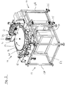
figures 1 ,2A and2B , a fillingstation 10 for filling cartridges of electronic cigarettes with a liquid is shown. Acartridge 40 is shown infigure 8 and will be discussed further below. Returning tofigure 1 , the filling station is intended to form part of a filling line. - The filling station comprises two parts, a
permanent part 12 and anexchangeable part 14 . Both parts comprise aframe 13A resp. 13B. - The
permanent part 12 comprises arotary conveyor 16, aninfeed device 18 and anoutfeed device 20. The rotary conveyor moves the cartridges around acentral axis 21. The rotary conveyor comprising anentry area 60 where the cartridges enter the rotary conveyor, a filling area 61 where the filling locations are provided and anexit area 62 where the cartridges leave the rotary conveyor. The cartridges are conveyed in groups. - In use, a group of
cartridges 40 are positioned in therespective filling locations 30 of the filling area 61 by the rotary conveyor. - The
exchangeable part 14 comprises a fillingunit 22 which is positioned overhead therotary conveyor 16. The rotary conveyor receives a group of cartridges from theinfeed device 18. The rotary conveyor subsequently moves the group in thedirection 24 to a filling area 61 underneath the fillingunit 22. The filling area comprises twenty filling positions. A different number is also possible. The filling positions are discussed in more detail further below. Subsequently the cartridges are filled. Next, the group of cartridges is moved to theoutfeed device 20, where the cartridges are removed from the rotary conveyor. - The
exchangeable part 14 is provided withwheels 25 in order to be exchanged for a similar exchangeable part. However, this is not essential to this invention. The exchangeable part could also be non-exchangeable and integrated with the permanent part. - Turning to
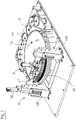
figure 2B , therotary conveyor 16 comprises three "pizza-slice"segments 17A, 17B, 17C which each hold a group of cartridges and rotate about themain axis 21. - Turning to
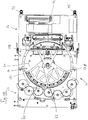
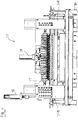
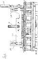
figures 3 ,4 and5 , the fillingunit 22 is shown in more detail. The filling unit comprises twoposts 26A, 26B and ahorizontal beam 27. Theposts 26A, 26B are positioned just outside therotary conveyor 16. Thebeam 27 is supported by theposts 26A, 26B and is positioned above therotary conveyor 16. The beam supports a plurality ofnozzles 35. - The filling station further comprises an up-
down actuator 38 for moving thenozzles 35 downward, into upwardly oriented filling openings of the cartridges in the filling positions 30. The up-down actuator is positioned on the post 26B. The up-down actuator 38 is an electric linear actuator but other types may also be used. The up-down actuator moves all nozzles downward simultaneously in order to insert a first nozzle and a second nozzle into each cartridge. All nozzles are inserted simultaneously. - Turning to
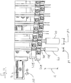
figures 6 ,7 and8 , a part of the filling unit is shown. The fillingunit 22 has twentypairs 32 ofnozzles 35. In top view, thepairs 32 are arranged as a part of a circle which matches the size and shape of therotary conveyor 16. The fillingstation 10 defines twenty fillingpositions 30 for a plurality of cartridges. The cartridges are filled simultaneously. Three fillingpositions 30 are shown infigure 6 . Obviously, the fillingstation 10 could also have a different number of filling positions than twenty. - Each
nozzle pair 32 has aleft nozzle 35A and aright nozzle 35B, also indicated as afirst nozzle 35A and asecond nozzle 35B. The nozzles are also collectively indicated bynumeral 35. The nozzles are grouped in afirst group 36A offirst nozzles 35A and a second group 36B ofsecond nozzles 35B. Thefirst group 36A and second group 36B are indicated schematically infigure 6 . - Each filling
position 30 is associated with afirst nozzle 35A from the first group and asecond nozzle 35B from the second group. - The nozzles have a shape which is somewhat similar to the shape of hypodermic needle, wherein the
opening 50A of each first nozzle faces theopening 50B of the associatedsecond nozzle 35B for each filling position. - As indicate in
figure 8 , each nozzle has alower tip 48 which is located eccentrically with respect to amain axis 49 of the said nozzle and wherein when the nozzle is in the inserted position thelower tip 48 of each nozzle is closer to a side wall of the cartridge than themain axis 49 of each nozzle. - The filling station further comprises a
distance actuator 39 for changing a horizontal distance (D) between eachfirst nozzle 35A andsecond nozzle 35B. The distance actuator is an electric linear actuator, but other actuators may be used. - The up-
down actuator 38 and thedistance actuator 39 are configured to move thefirst group 36A and second group 36B of nozzles into the cartridges, and to increase the distance between the respective first nozzles and second nozzles when they are inserted into the cartridges. - The up-
down actuator 38 is configured to further move the first and second group of nozzles into the cartridges after the distance between the respective first nozzles and second nozzles has been increased. - The
first group 36A of first nozzles are mounted on a commonfirst support member 42A. The second group of nozzles 36B are mounted on a commonsecond support member 42B. The first andsecond support members second support members rail 41 viasliders 43 which slide along therail 41 in the direction indicated byarrow 103. Therail 41 is mounted to theoverhead beam 27. The secondcommon support member 42B is located vertically above the firstcommon support member 42A. Thedistance actuator 39 is coupled with thecommon support members beams 101A, 101B and thesliders 43. - Turning to
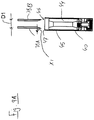
figures 9A ,9B ,9C and9D , thecartridge 40 is shown in more detail in a sectional view. The cartridge comprises awad 44 or non-woven for holding the liquid. The wad has a tubular shape. The cartridge has anupper opening 46. - Turning in particular to
figure 9A , the up-down actuator and the distance actuator are configured to insert the respective first and second nozzle into each cartridge when the first and second nozzle are at a first distance D1 from one another. - The first distance D1 is small enough to ensure that the nozzles remain at a distance X1 from the
side wall 45 of the cartridge. In this way, any collisions between the nozzles and theupper ridge 47 of theopening 46 are prevented. - Turning to
figure 9B , the situation is shown after thetips 48 of thenozzles cartridge 40 over a distance L1. The nozzles are in an intermediate position and not yet fully inserted. The distance between the nozzles is still D1, i.e. relatively small. - Subsequently, the distance is increase by the
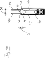
distance actuator 39 to the distance D2. This situation is shown infigure 9C . Thenozzles wall 45 or have a very small distance to thewall 45. The first andsecond nozzle - Turning to
figure 9D , subsequently thenozzles nozzles wad 44 and thewall 45. In this position, the liquid is ejected from the nozzles. The liquid is ejected directly into thewad 44. All cartridges are filled simultaneously. - In an embodiment the needles are moving upward during the liquid flow to create an even liquid distribution in the wad.
- After the filling of the cartridges, the
nozzles - Turning to
figure 10 , the fillingstation 10 is also configured to fill cartridges of different diameters P1, P2. Acartridge 40 having a relatively small diameter P1 is shown and a cartridge having a relatively large diameter P2 is shown. Thedistance actuator 39 can be adjusted to vary the distances D1, D2 in case the diameter of the cartridge varies. This is a relatively simple and straightforward process. - Likewise, the up-
down actuator 38 can also be adjusted to vary the distances L1 and L2 in case a height of the cartridge varies. This is a relatively simple and straightforward process. In this way, the filling station can be converted from one type of filling cartridge to another type of filling cartridge quite easily. - It will be understood that for each diameter and each length of the cartridge, a same kind of trajectory may be followed by the nozzles, i.e. inserting the nozzles to an intermediate position, increasing the distance between the nozzles and subsequently inserting the nozzles to the deepest position. The distances D1, D2, L1 and L2 may be adjusted for each type of nozzle. These distances may be pre-set in a control unit so that the conversion can be carried out fast and with little downtime.
- It will be recognized that an embodiment may not achieve all of the stated objects.
- As required, detailed embodiments of the present invention are disclosed herein; however, it is to be understood that the disclosed embodiments are merely exemplary of the invention, which can be embodied in various forms. Therefore, specific structural and functional details disclosed herein are not to be interpreted as limiting, but merely as a basis for the claims and as a representative basis for teaching one skilled in the art to variously employ the present invention in virtually any appropriately detailed structure. Further, the terms and phrases used herein are not intended to be limiting, but rather, to provide an understandable description of the invention.
- The terms "a" or "an", as used herein, are defined as one or more than one. The term plurality, as used herein, is defined as two or more than two. The term another, as used herein, is defined as at least a second or more. The terms including and/or having, as used herein, are defined as comprising (i.e., open language, not excluding other elements or steps). Any reference signs in the claims should not be construed as limiting the scope of the claims or the invention.
- The mere fact that certain measures are recited in mutually different dependent claims does not indicate that a combination of these measures cannot be used to advantage.
Claims (15)
- Filling station (10) for filling cartridges (40) of electronic cigarettes with a liquid, the filling station defining a plurality of filling positions (30) for a plurality of cartridges, the filling station being configured for simultaneously filling the cartridges which are in the filling positions, the filling station comprising:- a plurality of nozzles (35), wherein the nozzles are grouped in:∘ a first group (36A) of first nozzles (35A) and∘ a second group (36B) of second nozzles (35B),wherein each filling position is associated with a first nozzle (35A) from the first group and a second nozzle (35B) from the second group,- an up-down actuator (38) for moving the nozzles (35) downward into upwardly oriented filling openings (46) of the cartridges in the filling positions in order to insert at least a first nozzle and a second nozzle into each cartridge, and- a distance actuator (39) for changing a horizontal distance (D) between each first nozzle and second nozzle.
- Filling station according to claim 1, wherein:- the up-down actuator (38) is configured to move the first and second group of nozzles into and out of the cartridges, and- the distance actuator (39) is configured to increase and decrease the distance between the respective first nozzles and second nozzles while they are inserted into the cartridges.
- Filling station according to claim 2, wherein the up-down actuator is configured to further move the first and second group of nozzles into the cartridges after the distance between the respective first nozzles and second nozzles has been increased by the distance actuator.
- Filling station according to any of the preceding claims, wherein the up-down actuator and the distance actuator are configured to insert the respective first and second nozzle into each cartridge between the wall (45) of the cartridge and a wad (44) which is located inside the cartridge, and wherein the first and second nozzle are inserted on opposite sides of the cartridge.
- Filling station according to any of the preceding claims, wherein the up-down actuator and the distance actuator are configured to - after the filling of the cartridges - retract the respective first nozzles and second nozzles partially from the cartridges over a distance and to subsequently decrease the distance between the respective first nozzles and second nozzles, and wherein the up-down actuator and the distance actuator are configured to fully retract the respective first nozzles and second nozzles from the cartridges after the distance between the respective first nozzles and second nozzles has been decreased.
- Filling station according to any of the preceding claims, wherein the nozzles of the first group are mounted to a common first support member (42A) and the nozzles of the second group are mounted to a common second support member (42B), wherein the first and second common support member are moveable relative to one another over a horizontal distance, wherein the filling station comprises an overhead beam (27) which extends above the filling area, wherein a rail (41) is mounted to said overhead beam, and wherein the common first and second support members (42A, 42B) are connected to said rail via sliders (43) and are movable from left to right and vice versa.
- Filling station according to any of the preceding claims, wherein the nozzles have a needle shape comprising an opening or an inclined surface, wherein the opening or inclined surface of each first nozzle faces the opening or inclined surface of the associated second nozzle for each filling position, and wherein each nozzle has a lower tip (48) which is located eccentrically with respect to a main axis (49) of the said nozzle and wherein when the nozzle is in the inserted position the lower tip of each nozzle is closer to a side wall of the cartridge than the main axis of each nozzle.
- Filling station according to any of the preceding claims, configured to simultaneously insert all nozzles into the filling openings of the cartridges situated in the filling positions.
- Filling station according to any of the preceding claims, wherein when seen in top view the filling locations are arranged along a part of a circle and the pairs of nozzles are arranged along a part of a same or similar circle in order to match with the arrangement of the filling locations, and wherein the filling station comprises a rotary conveyor (16) for revolving the cartridges around a central axis (21), the rotary conveyor being supported by a support frame (13A), the rotary conveyor comprising an entry area (60) where the cartridges enter the rotary conveyor, a filling area (61) where the filling locations are provided and an exit area (62) where the cartridges leave the rotary conveyor.
- Method of filling cartridges for electronic cigarettes, the method comprising:- providing the filling station (10) according to any of the preceding claims,- positioning a number of cartridges (40) in the respective filling locations (30),- inserting the nozzles of the first and second group into the respective cartridges,- filling each cartridge by ejecting a liquid through the respective first and second nozzles, and- retracting the nozzles from the cartridges,wherein the method comprises changing the distance (D) between the respective nozzles of the first group and the respective nozzles of the second group.
- Method according to the preceding claim, comprising:- inserting the nozzles into the cartridges, wherein the respective first and second nozzle for each filling position are positioned at first distance (D1) from one another,- increasing the distance between the first and second nozzles to a second distance (D2) when the nozzles are in the inserted position, and- inserting the nozzles further to a deepest position.
- Method according to claim 10 or 11, comprising further inserting the nozzles into the cartridges after the distance has been increased, and comprising inserting each nozzle into the cartridge between the side wall of the cartridge and the wad.
- Method according to any of the preceding claims 10-12, wherein the nozzles are moved upwardly during the filling in order to fill the wads substantially evenly.
- Method of filling cartridges of electronic cigarettes, the method comprising:- providing the filling station according to any of claims 1 - 9,- filling a number of cartridges of a first size, wherein the respective first and second nozzles are positioned at a first distance from one another during the filling,- adjusting the filling station by changing the distance between the nozzles from the first distance to a second distance, and- filling a number of cartridges of a second size, wherein the respective first and second nozzles are positioned at the second distance from one another during the filling.
- Method according to any of the preceding claims 10-14, wherein the first and second group of nozzles are simultaneously inserted into the openings of the respective cartridges.
Priority Applications (1)
| Application Number | Priority Date | Filing Date | Title |
|---|---|---|---|
| PL16744897T PL3307635T3 (en) | 2015-06-09 | 2016-06-01 | Filling station and method for filling cartridges of electronic cigarettes with a liquid |
Applications Claiming Priority (2)
| Application Number | Priority Date | Filing Date | Title |
|---|---|---|---|
| NL2014946A NL2014946B1 (en) | 2015-06-09 | 2015-06-09 | Filling station and method for filling cartridges of electronic cigarettes with a liquid. |
| PCT/NL2016/050392 WO2016200253A1 (en) | 2015-06-09 | 2016-06-01 | Filing station and method for filing cartridges of electronic cigarettes with a liquid |
Publications (2)
| Publication Number | Publication Date |
|---|---|
| EP3307635A1 EP3307635A1 (en) | 2018-04-18 |
| EP3307635B1 true EP3307635B1 (en) | 2019-05-01 |
Family
ID=53783857
Family Applications (1)
| Application Number | Title | Priority Date | Filing Date |
|---|---|---|---|
| EP16744897.6A Active EP3307635B1 (en) | 2015-06-09 | 2016-06-01 | Filling station and method for filling cartridges of electronic cigarettes with a liquid |
Country Status (7)
| Country | Link |
|---|---|
| US (1) | US10407196B2 (en) |
| EP (1) | EP3307635B1 (en) |
| JP (1) | JP6730330B2 (en) |
| HU (1) | HUE044250T2 (en) |
| NL (1) | NL2014946B1 (en) |
| PL (1) | PL3307635T3 (en) |
| WO (1) | WO2016200253A1 (en) |
Families Citing this family (22)
| Publication number | Priority date | Publication date | Assignee | Title |
|---|---|---|---|---|
| US10244793B2 (en) | 2005-07-19 | 2019-04-02 | Juul Labs, Inc. | Devices for vaporization of a substance |
| US10279934B2 (en) | 2013-03-15 | 2019-05-07 | Juul Labs, Inc. | Fillable vaporizer cartridge and method of filling |
| US10512282B2 (en) | 2014-12-05 | 2019-12-24 | Juul Labs, Inc. | Calibrated dose control |
| US10058129B2 (en) | 2013-12-23 | 2018-08-28 | Juul Labs, Inc. | Vaporization device systems and methods |
| USD842536S1 (en) | 2016-07-28 | 2019-03-05 | Juul Labs, Inc. | Vaporizer cartridge |
| USD825102S1 (en) | 2016-07-28 | 2018-08-07 | Juul Labs, Inc. | Vaporizer device with cartridge |
| PT3508080T (en) | 2013-12-23 | 2021-03-02 | Juul Labs Int Inc | Vaporization device systems and methods |
| US10159282B2 (en) | 2013-12-23 | 2018-12-25 | Juul Labs, Inc. | Cartridge for use with a vaporizer device |
| US10076139B2 (en) | 2013-12-23 | 2018-09-18 | Juul Labs, Inc. | Vaporizer apparatus |
| US20160366947A1 (en) | 2013-12-23 | 2016-12-22 | James Monsees | Vaporizer apparatus |
| MX2018009703A (en) | 2016-02-11 | 2019-07-08 | Juul Labs Inc | Securely attaching cartridges for vaporizer devices. |
| UA125687C2 (en) | 2016-02-11 | 2022-05-18 | Джуул Лебз, Інк. | Fillable vaporizer cartridge and method of filling |
| US10405582B2 (en) | 2016-03-10 | 2019-09-10 | Pax Labs, Inc. | Vaporization device with lip sensing |
| USD849996S1 (en) | 2016-06-16 | 2019-05-28 | Pax Labs, Inc. | Vaporizer cartridge |
| USD836541S1 (en) | 2016-06-23 | 2018-12-25 | Pax Labs, Inc. | Charging device |
| USD851830S1 (en) | 2016-06-23 | 2019-06-18 | Pax Labs, Inc. | Combined vaporizer tamp and pick tool |
| KR102327122B1 (en) | 2016-12-12 | 2021-11-16 | 브이엠알 프로덕츠 엘엘씨 | carburetor cartridge |
| IT201700016823A1 (en) * | 2017-02-15 | 2018-08-15 | Gd Spa | Method and device for filling a cartridge for an aerosol generating device with a liquid. |
| IT201700072733A1 (en) * | 2017-06-29 | 2018-12-29 | Gd Spa | System for assembling and filling two groups of electronic cigarettes. |
| USD887632S1 (en) | 2017-09-14 | 2020-06-16 | Pax Labs, Inc. | Vaporizer cartridge |
| EP3717363B1 (en) * | 2017-12-01 | 2021-09-01 | G.D S.p.A. | Station and method for filling cartridges of electronic cigarettes |
| USD1028336S1 (en) | 2021-06-22 | 2024-05-21 | Pax Labs, Inc. | Vaporizer cartridge |
Family Cites Families (8)
| Publication number | Priority date | Publication date | Assignee | Title |
|---|---|---|---|---|
| JPH05329384A (en) * | 1992-05-29 | 1993-12-14 | Shimadzu Corp | Liquid pipetting device |
| US5305809A (en) * | 1992-10-20 | 1994-04-26 | R & D Innovators, Inc. | Gang array filler with relocatable nozzles |
| GB2323081A (en) * | 1998-05-29 | 1998-09-16 | Unilever Plc | Nozzle for a filling machine |
| DE10152234A1 (en) * | 2001-10-20 | 2003-07-24 | Bosch Gmbh Robert | Device for measured filling of containers with liquid of low viscosity, whereby multiple filling lines with matching filling needles are used to enable high speed filling and relatively simple cleaning |
| JP2003175997A (en) * | 2001-12-12 | 2003-06-24 | Seiko Corp | Liquid filling apparatus |
| JP2005034021A (en) * | 2003-07-17 | 2005-02-10 | Seiko Epson Corp | Electronic cigarette |
| PL2639163T3 (en) * | 2012-03-15 | 2015-03-31 | Antonio Mengibar S A | Method and apparatus for generating a filling pattern for filling containers |
| ITBO20130504A1 (en) | 2013-09-18 | 2015-03-19 | Gd Spa | METHOD AND FILLING UNIT OF A DISPOSABLE CARTRIDGE FOR ELECTRONIC CIGARETTES WITH A LIQUID SUBSTANCE. |
-
2015
- 2015-06-09 NL NL2014946A patent/NL2014946B1/en not_active IP Right Cessation
-
2016
- 2016-06-01 US US15/578,462 patent/US10407196B2/en active Active
- 2016-06-01 HU HUE16744897 patent/HUE044250T2/en unknown
- 2016-06-01 WO PCT/NL2016/050392 patent/WO2016200253A1/en active Application Filing
- 2016-06-01 EP EP16744897.6A patent/EP3307635B1/en active Active
- 2016-06-01 JP JP2017563198A patent/JP6730330B2/en not_active Expired - Fee Related
- 2016-06-01 PL PL16744897T patent/PL3307635T3/en unknown
Non-Patent Citations (1)
| Title |
|---|
| None * |
Also Published As
| Publication number | Publication date |
|---|---|
| WO2016200253A1 (en) | 2016-12-15 |
| PL3307635T3 (en) | 2019-09-30 |
| NL2014946A (en) | 2016-12-12 |
| HUE044250T2 (en) | 2019-10-28 |
| US20180134429A1 (en) | 2018-05-17 |
| NL2014946B1 (en) | 2017-01-31 |
| EP3307635A1 (en) | 2018-04-18 |
| JP2018519216A (en) | 2018-07-19 |
| JP6730330B2 (en) | 2020-07-29 |
| US10407196B2 (en) | 2019-09-10 |
Similar Documents
| Publication | Publication Date | Title |
|---|---|---|
| EP3307635B1 (en) | Filling station and method for filling cartridges of electronic cigarettes with a liquid | |
| DE602004006164T2 (en) | FEEDING SYSTEM FOR FOREQUARTERS, IN PARTICULAR A CONTAINER BLASFORMING MACHINE, CONTAINING MEANS OF EXHAUSTING BADLY POSITIONED PREFORMS | |
| NL2014045B1 (en) | Device for filling cartridges of e-cigarettes with a liquid. | |
| EP2049401B2 (en) | Method of shrinking a shrink-fit film onto packs | |
| EP2651368B1 (en) | Device for introducing filling material into capsules | |
| DE102010061447A1 (en) | Intermittent rotating machine for filling capsules with pharmaceutical products | |
| EP2931633B1 (en) | Container filling machine provided with a linear drive | |
| DE102010061446A1 (en) | Intermittently rotating machine for filling capsules with pharmaceutical products | |
| DE102010061444A1 (en) | Intermittent rotating machine for filling capsules with pharmaceutical products | |
| US10046923B2 (en) | Device for dividing off packaging units | |
| DE202016101207U1 (en) | Transport device for the row-wise transfer of cargo items prone to breakdown and the formation of layers | |
| EP3414194B1 (en) | Method and device for grouping product blanks | |
| DE3344907C2 (en) | Device for supplying cigarettes | |
| EP2049063B1 (en) | Device and method for ejecting at least one capsule. | |
| DE2365942A1 (en) | DEVICE FOR ALIGNING CONTAINERS | |
| EP3930944B1 (en) | Method and device for producing three-dimensional components by selective solidification | |
| EP2455325B1 (en) | Method and device for filling containers | |
| DE3829223C2 (en) | ||
| EP3398863B1 (en) | Apparatus and method for forming groups of products | |
| US3491804A (en) | Apparatus for filling containers or the like with fluent or flowable material | |
| DE530638C (en) | Device for ejecting bottles on bottle washing machines by means of an ejector | |
| DE102013106553B4 (en) | Stacking device and stacking method | |
| EP0079051A1 (en) | Device for inserting giblets into a cockerel cavity | |
| DE1278382B (en) | Device for the automatic exchange of lap carriers on spools of thread | |
| DE102020120284A1 (en) | Device for treating container blanks |
Legal Events
| Date | Code | Title | Description |
|---|---|---|---|
| STAA | Information on the status of an ep patent application or granted ep patent |
Free format text: STATUS: THE INTERNATIONAL PUBLICATION HAS BEEN MADE |
|
| PUAI | Public reference made under article 153(3) epc to a published international application that has entered the european phase |
Free format text: ORIGINAL CODE: 0009012 |
|
| STAA | Information on the status of an ep patent application or granted ep patent |
Free format text: STATUS: REQUEST FOR EXAMINATION WAS MADE |
|
| 17P | Request for examination filed |
Effective date: 20171129 |
|
| AK | Designated contracting states |
Kind code of ref document: A1 Designated state(s): AL AT BE BG CH CY CZ DE DK EE ES FI FR GB GR HR HU IE IS IT LI LT LU LV MC MK MT NL NO PL PT RO RS SE SI SK SM TR |
|
| AX | Request for extension of the european patent |
Extension state: BA ME |
|
| DAV | Request for validation of the european patent (deleted) | ||
| DAX | Request for extension of the european patent (deleted) | ||
| RIC1 | Information provided on ipc code assigned before grant |
Ipc: B65B 3/00 20060101ALI20181018BHEP Ipc: B65B 35/46 20060101ALI20181018BHEP Ipc: B65B 3/04 20060101ALI20181018BHEP Ipc: B65B 59/00 20060101ALI20181018BHEP Ipc: B67C 3/22 20060101ALI20181018BHEP Ipc: B65B 39/00 20060101ALI20181018BHEP Ipc: B65B 39/12 20060101AFI20181018BHEP Ipc: B65B 59/04 20060101ALI20181018BHEP |
|
| GRAP | Despatch of communication of intention to grant a patent |
Free format text: ORIGINAL CODE: EPIDOSNIGR1 |
|
| STAA | Information on the status of an ep patent application or granted ep patent |
Free format text: STATUS: GRANT OF PATENT IS INTENDED |
|
| INTG | Intention to grant announced |
Effective date: 20190107 |
|
| GRAS | Grant fee paid |
Free format text: ORIGINAL CODE: EPIDOSNIGR3 |
|
| GRAA | (expected) grant |
Free format text: ORIGINAL CODE: 0009210 |
|
| STAA | Information on the status of an ep patent application or granted ep patent |
Free format text: STATUS: THE PATENT HAS BEEN GRANTED |
|
| AK | Designated contracting states |
Kind code of ref document: B1 Designated state(s): AL AT BE BG CH CY CZ DE DK EE ES FI FR GB GR HR HU IE IS IT LI LT LU LV MC MK MT NL NO PL PT RO RS SE SI SK SM TR |
|
| REG | Reference to a national code |
Ref country code: GB Ref legal event code: FG4D |
|
| REG | Reference to a national code |
Ref country code: CH Ref legal event code: EP Ref country code: AT Ref legal event code: REF Ref document number: 1126619 Country of ref document: AT Kind code of ref document: T Effective date: 20190515 |
|
| REG | Reference to a national code |
Ref country code: DE Ref legal event code: R096 Ref document number: 602016013309 Country of ref document: DE |
|
| REG | Reference to a national code |
Ref country code: IE Ref legal event code: FG4D |
|
| REG | Reference to a national code |
Ref country code: CH Ref legal event code: NV Representative=s name: SAEGER AND PARTNER PATENT- UND RECHTSANWAELTE, CH |
|
| REG | Reference to a national code |
Ref country code: NL Ref legal event code: FP |
|
| REG | Reference to a national code |
Ref country code: RO Ref legal event code: EPE |
|
| REG | Reference to a national code |
Ref country code: LT Ref legal event code: MG4D |
|
| REG | Reference to a national code |
Ref country code: HU Ref legal event code: AG4A Ref document number: E044250 Country of ref document: HU |
|
| PG25 | Lapsed in a contracting state [announced via postgrant information from national office to epo] |
Ref country code: FI Free format text: LAPSE BECAUSE OF FAILURE TO SUBMIT A TRANSLATION OF THE DESCRIPTION OR TO PAY THE FEE WITHIN THE PRESCRIBED TIME-LIMIT Effective date: 20190501 Ref country code: LT Free format text: LAPSE BECAUSE OF FAILURE TO SUBMIT A TRANSLATION OF THE DESCRIPTION OR TO PAY THE FEE WITHIN THE PRESCRIBED TIME-LIMIT Effective date: 20190501 Ref country code: ES Free format text: LAPSE BECAUSE OF FAILURE TO SUBMIT A TRANSLATION OF THE DESCRIPTION OR TO PAY THE FEE WITHIN THE PRESCRIBED TIME-LIMIT Effective date: 20190501 Ref country code: PT Free format text: LAPSE BECAUSE OF FAILURE TO SUBMIT A TRANSLATION OF THE DESCRIPTION OR TO PAY THE FEE WITHIN THE PRESCRIBED TIME-LIMIT Effective date: 20190901 Ref country code: HR Free format text: LAPSE BECAUSE OF FAILURE TO SUBMIT A TRANSLATION OF THE DESCRIPTION OR TO PAY THE FEE WITHIN THE PRESCRIBED TIME-LIMIT Effective date: 20190501 Ref country code: SE Free format text: LAPSE BECAUSE OF FAILURE TO SUBMIT A TRANSLATION OF THE DESCRIPTION OR TO PAY THE FEE WITHIN THE PRESCRIBED TIME-LIMIT Effective date: 20190501 Ref country code: AL Free format text: LAPSE BECAUSE OF FAILURE TO SUBMIT A TRANSLATION OF THE DESCRIPTION OR TO PAY THE FEE WITHIN THE PRESCRIBED TIME-LIMIT Effective date: 20190501 Ref country code: NO Free format text: LAPSE BECAUSE OF FAILURE TO SUBMIT A TRANSLATION OF THE DESCRIPTION OR TO PAY THE FEE WITHIN THE PRESCRIBED TIME-LIMIT Effective date: 20190801 |
|
| PG25 | Lapsed in a contracting state [announced via postgrant information from national office to epo] |
Ref country code: GR Free format text: LAPSE BECAUSE OF FAILURE TO SUBMIT A TRANSLATION OF THE DESCRIPTION OR TO PAY THE FEE WITHIN THE PRESCRIBED TIME-LIMIT Effective date: 20190802 Ref country code: RS Free format text: LAPSE BECAUSE OF FAILURE TO SUBMIT A TRANSLATION OF THE DESCRIPTION OR TO PAY THE FEE WITHIN THE PRESCRIBED TIME-LIMIT Effective date: 20190501 Ref country code: LV Free format text: LAPSE BECAUSE OF FAILURE TO SUBMIT A TRANSLATION OF THE DESCRIPTION OR TO PAY THE FEE WITHIN THE PRESCRIBED TIME-LIMIT Effective date: 20190501 Ref country code: BG Free format text: LAPSE BECAUSE OF FAILURE TO SUBMIT A TRANSLATION OF THE DESCRIPTION OR TO PAY THE FEE WITHIN THE PRESCRIBED TIME-LIMIT Effective date: 20190801 |
|
| REG | Reference to a national code |
Ref country code: AT Ref legal event code: MK05 Ref document number: 1126619 Country of ref document: AT Kind code of ref document: T Effective date: 20190501 |
|
| PG25 | Lapsed in a contracting state [announced via postgrant information from national office to epo] |
Ref country code: IS Free format text: LAPSE BECAUSE OF FAILURE TO SUBMIT A TRANSLATION OF THE DESCRIPTION OR TO PAY THE FEE WITHIN THE PRESCRIBED TIME-LIMIT Effective date: 20190901 |
|
| PG25 | Lapsed in a contracting state [announced via postgrant information from national office to epo] |
Ref country code: SK Free format text: LAPSE BECAUSE OF FAILURE TO SUBMIT A TRANSLATION OF THE DESCRIPTION OR TO PAY THE FEE WITHIN THE PRESCRIBED TIME-LIMIT Effective date: 20190501 Ref country code: AT Free format text: LAPSE BECAUSE OF FAILURE TO SUBMIT A TRANSLATION OF THE DESCRIPTION OR TO PAY THE FEE WITHIN THE PRESCRIBED TIME-LIMIT Effective date: 20190501 Ref country code: MC Free format text: LAPSE BECAUSE OF FAILURE TO SUBMIT A TRANSLATION OF THE DESCRIPTION OR TO PAY THE FEE WITHIN THE PRESCRIBED TIME-LIMIT Effective date: 20190501 Ref country code: EE Free format text: LAPSE BECAUSE OF FAILURE TO SUBMIT A TRANSLATION OF THE DESCRIPTION OR TO PAY THE FEE WITHIN THE PRESCRIBED TIME-LIMIT Effective date: 20190501 Ref country code: DK Free format text: LAPSE BECAUSE OF FAILURE TO SUBMIT A TRANSLATION OF THE DESCRIPTION OR TO PAY THE FEE WITHIN THE PRESCRIBED TIME-LIMIT Effective date: 20190501 |
|
| REG | Reference to a national code |
Ref country code: DE Ref legal event code: R097 Ref document number: 602016013309 Country of ref document: DE |
|
| PG25 | Lapsed in a contracting state [announced via postgrant information from national office to epo] |
Ref country code: SM Free format text: LAPSE BECAUSE OF FAILURE TO SUBMIT A TRANSLATION OF THE DESCRIPTION OR TO PAY THE FEE WITHIN THE PRESCRIBED TIME-LIMIT Effective date: 20190501 |
|
| PLBE | No opposition filed within time limit |
Free format text: ORIGINAL CODE: 0009261 |
|
| STAA | Information on the status of an ep patent application or granted ep patent |
Free format text: STATUS: NO OPPOSITION FILED WITHIN TIME LIMIT |
|
| REG | Reference to a national code |
Ref country code: BE Ref legal event code: MM Effective date: 20190630 |
|
| PG25 | Lapsed in a contracting state [announced via postgrant information from national office to epo] |
Ref country code: TR Free format text: LAPSE BECAUSE OF FAILURE TO SUBMIT A TRANSLATION OF THE DESCRIPTION OR TO PAY THE FEE WITHIN THE PRESCRIBED TIME-LIMIT Effective date: 20190501 |
|
| 26N | No opposition filed |
Effective date: 20200204 |
|
| PG25 | Lapsed in a contracting state [announced via postgrant information from national office to epo] |
Ref country code: IE Free format text: LAPSE BECAUSE OF NON-PAYMENT OF DUE FEES Effective date: 20190601 |
|
| PG25 | Lapsed in a contracting state [announced via postgrant information from national office to epo] |
Ref country code: SI Free format text: LAPSE BECAUSE OF FAILURE TO SUBMIT A TRANSLATION OF THE DESCRIPTION OR TO PAY THE FEE WITHIN THE PRESCRIBED TIME-LIMIT Effective date: 20190501 Ref country code: LU Free format text: LAPSE BECAUSE OF NON-PAYMENT OF DUE FEES Effective date: 20190601 Ref country code: BE Free format text: LAPSE BECAUSE OF NON-PAYMENT OF DUE FEES Effective date: 20190630 |
|
| PG25 | Lapsed in a contracting state [announced via postgrant information from national office to epo] |
Ref country code: FR Free format text: LAPSE BECAUSE OF NON-PAYMENT OF DUE FEES Effective date: 20190701 |
|
| PG25 | Lapsed in a contracting state [announced via postgrant information from national office to epo] |
Ref country code: CY Free format text: LAPSE BECAUSE OF FAILURE TO SUBMIT A TRANSLATION OF THE DESCRIPTION OR TO PAY THE FEE WITHIN THE PRESCRIBED TIME-LIMIT Effective date: 20190501 |
|
| PG25 | Lapsed in a contracting state [announced via postgrant information from national office to epo] |
Ref country code: MT Free format text: LAPSE BECAUSE OF FAILURE TO SUBMIT A TRANSLATION OF THE DESCRIPTION OR TO PAY THE FEE WITHIN THE PRESCRIBED TIME-LIMIT Effective date: 20190501 |
|
| PG25 | Lapsed in a contracting state [announced via postgrant information from national office to epo] |
Ref country code: MK Free format text: LAPSE BECAUSE OF FAILURE TO SUBMIT A TRANSLATION OF THE DESCRIPTION OR TO PAY THE FEE WITHIN THE PRESCRIBED TIME-LIMIT Effective date: 20190501 |
|
| PGFP | Annual fee paid to national office [announced via postgrant information from national office to epo] |
Ref country code: NL Payment date: 20220627 Year of fee payment: 7 |
|
| P01 | Opt-out of the competence of the unified patent court (upc) registered |
Effective date: 20230522 |
|
| PGFP | Annual fee paid to national office [announced via postgrant information from national office to epo] |
Ref country code: RO Payment date: 20230518 Year of fee payment: 8 Ref country code: DE Payment date: 20230620 Year of fee payment: 8 Ref country code: CZ Payment date: 20230519 Year of fee payment: 8 |
|
| PGFP | Annual fee paid to national office [announced via postgrant information from national office to epo] |
Ref country code: PL Payment date: 20230524 Year of fee payment: 8 Ref country code: HU Payment date: 20230531 Year of fee payment: 8 |
|
| PGFP | Annual fee paid to national office [announced via postgrant information from national office to epo] |
Ref country code: IT Payment date: 20230630 Year of fee payment: 8 Ref country code: GB Payment date: 20230622 Year of fee payment: 8 Ref country code: CH Payment date: 20230702 Year of fee payment: 8 |
|
| REG | Reference to a national code |
Ref country code: NL Ref legal event code: MM Effective date: 20230701 |
|
| PG25 | Lapsed in a contracting state [announced via postgrant information from national office to epo] |
Ref country code: NL Free format text: LAPSE BECAUSE OF NON-PAYMENT OF DUE FEES Effective date: 20230701 |