EP3307401B1 - Integral safety harness connector assembly - Google Patents
Integral safety harness connector assembly Download PDFInfo
- Publication number
- EP3307401B1 EP3307401B1 EP16734078.5A EP16734078A EP3307401B1 EP 3307401 B1 EP3307401 B1 EP 3307401B1 EP 16734078 A EP16734078 A EP 16734078A EP 3307401 B1 EP3307401 B1 EP 3307401B1
- Authority
- EP
- European Patent Office
- Prior art keywords
- connector
- safety harness
- end portion
- ring
- passage
- Prior art date
- Legal status (The legal status is an assumption and is not a legal conclusion. Google has not performed a legal analysis and makes no representation as to the accuracy of the status listed.)
- Active
Links
Images


Classifications
-
- A—HUMAN NECESSITIES
- A62—LIFE-SAVING; FIRE-FIGHTING
- A62B—DEVICES, APPARATUS OR METHODS FOR LIFE-SAVING
- A62B35/00—Safety belts or body harnesses; Similar equipment for limiting displacement of the human body, especially in case of sudden changes of motion
-
- A—HUMAN NECESSITIES
- A62—LIFE-SAVING; FIRE-FIGHTING
- A62B—DEVICES, APPARATUS OR METHODS FOR LIFE-SAVING
- A62B35/00—Safety belts or body harnesses; Similar equipment for limiting displacement of the human body, especially in case of sudden changes of motion
- A62B35/0006—Harnesses; Accessories therefor
- A62B35/0025—Details and accessories
- A62B35/0031—Belt sorting accessories, e.g. devices keeping the belts in comfortable positions
-
- A—HUMAN NECESSITIES
- A62—LIFE-SAVING; FIRE-FIGHTING
- A62B—DEVICES, APPARATUS OR METHODS FOR LIFE-SAVING
- A62B35/00—Safety belts or body harnesses; Similar equipment for limiting displacement of the human body, especially in case of sudden changes of motion
- A62B35/0006—Harnesses; Accessories therefor
- A62B35/0025—Details and accessories
- A62B35/0037—Attachments for lifelines and lanyards
Definitions
- Such apparatus usually include a safety line interconnected between a support structure and a person working in proximity to the support structure.
- the safety line is typically secured to a full-body safety harness worn by the worker.
- a connector may be used to interconnect the safety line and the full-body safety harness as well as provide a connection for other attachments to the safety harness.
- the connector must be reliable and able to withstand the forces of a fall.
- it is preferred that the connector be user friendly.
- An example of a safety harness connector assembly is known from US2015/107059 A1 .
- a safety harness connector assembly is provided as set out in claim 1.
- the safety harness connector assembly includes a D-ring, a device connector system and a shaft.
- the D-ring is generally a C-shape including a first end portion, a second end portion and mid-portion. The mid-portion extends between the first end portion and the second end portion.
- the first end portion has a first D-ring aperture and the second end portion having a second D-ring aperture.
- the first D-ring aperture is aligned with the second D-ring aperture.
- the device connector system includes at least one device connection aperture that is configured and arranged to couple a device to the safety harness connector assembly.
- the device connector system comprises a base member having at least one shaft connection aperture.
- a shaft is received in the first and second D-ring apertures of the D-ring and in the at least one shaft connection aperture of the base member device connector system to pivotally couple the base member of the device connector system to the D-ring
- the device connector system further comprises: a first connector member pivotally coupled to the base member, the first connector member having a first device connection passage; a swivel connector pivotally coupled to the first connector member; and a second connector member pivotally coupled to the swivel connector, the second connector member having a second device connection passage, the first device connection passage of the first connector member and the second device connection passage of the second connector member forming a first device connection aperture and a second device connection aperture of the device connector system, respectively.
- Embodiments of the present invention provide an integral safety harness connector assembly.
- the safety harness connector assembly can be used to couple any type of device to a safety harness such as, but not limited to, a self retracting lifeline (SRL) system.
- SRL self retracting lifeline
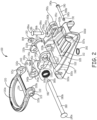
- a first embodiment of the safety harness connector assembly 100 is illustrated in Figure 1 .
- the safety harness connector assembly 100 includes a D-ring 120, a base dorsal member 102 a device connector system 125.
- the elements of the safety harness connector assembly 100 are further described in view of the unassembled view provided in Figure 2 .
- the D ring 120 is generally C shaped having a mid-portion 120a, a first end portion 120b and a second end portion 120c.
- a brace 124 extends across the D-ring 120 proximate the first end portion 120b and the second end portion 120c.
- Each of the first end portion 120b and the second end portion 120c includes a respective D-ring aperture 121b and 121c.
- the D-ring apertures 121b and 121c are aligned with each other.
- the first end portion 120b includes an extending sleeve portion 122 that is positioned around the ring aperture 121b.
- the sleeve portion 122 includes a biasing receiving slot 123.
- a biasing member 182 (a torsion spring in this example embodiment) is received within the biasing receiving slot 123 of the sleeve portion 122 to assert a biasing force on the D-ring 120 to position the D-ring 120 to be at a desired position in relation to the base dorsal member 102.
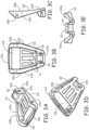
- the base dorsal member 102 is further shown in Figures 3A through 3E .
- the base dorsal member 102 includes a front side surface 102a and a back side surface 102b. Further, the base dorsal member 102 includes an upper edge 102c and an opposed lower edge 102d. Moreover, the base dorsal member 102 includes a first side edge 102e and an opposed second side edge 102f as illustrated in Figure 3B . As illustrated in the Figures, the upper edge 102c has a greater length than the lower edge 102d of the base dorsal member 102. Extending along the length of the first side edge 102e is a first side wall 104a.
- the first side wall 104a has a height that varies along its length. In the embodiment, the height of the first side wall 104a has a low height at the lower edge 102d. From the lower edge 102d, the height of the first wall 104a increases until the height of the first wall 104a reaches a maximum height at a select location. The select location of the maximum height is near the upper edge 102c. The height of the first wall 104a then decreases from the point of maximum height to the upper edge 102c.
- the base dorsal member 102 further includes a second side wall 104b that extends along the length of the second side edge 102f. In one embodiment, the second side wall 104b is a mirror image of the first side wall 104a.
- a mid-plate portion 106 Positioned between the first and second side walls 104a and 104b is a mid-plate portion 106.
- the first side wall 104a, the second side wall 104b and the mid-plate portion 106 form a holding tray 112 for elements of the safety harness connection assembly 100.
- the mid-plate portion 106 includes a plurality of shaped slots 111 in this embodiment.
- the mid-plate portion 106 only extends a portion of a distance between the lower edge 102d and the upper edge 102c of the base dorsal member 102.
- a webbing passage 105 is positioned between the mid-plate portion 106 and the upper edge 102c of the base dorsal member 102.
- Each of the first and second side walls 104a and 104b includes a respective dorsal aperture 103a and 103b.
- the respective dorsal apertures 103a and 103b are aligned with each other and are positioned in the respective first and second side walls 104a and 104b at a location that is proximate the location of the maximum height of the respective first and second sidewalls 104a and 104b.
- the respective dorsal apertures 103a and 103b are positioned on opposite sides of the webbing passage 105.
- the base dorsal member 102 further includes a biasing arm holding slot 113 which is illustrated in Figure 3D .
- the biasing holding member slot 113 holds an arm of biasing member 182.
- the load attachment member 110 in one embodiment is used to attach a load distribution system 296 of a safety harness 298 (shown generally in Figure 5D ) to the safety harness connection assembly 100.
- the load attachment member 110 includes a pair of aligned spaced load attachment apertures 107a and 107b and a cavity 115.
- a clevis pin 190 passes through the load attachment apertures 107a and 107b to couple a portion the load distribution system 296 of the safety harness 298, received in the cavity, to the safety harness connection assembly 100.
- the clevis pin 190 in this example embodiment, includes a head 190a, a pin mid-portion 190b and an end portion 190c.
- a ring aperture 191 In the end portion 190c is a ring aperture 191 that is designed to receive a split ring 192 to lock the clevis pin 190 to the load attachment member 110.
- the D-ring 120 is coupled to the base dorsal member 102 via dorsal rivet 180.
- the dorsal rivet 180 includes a head 180a, a mid-shaft portion 180b and end portion 180c.
- the end portion 180c of the dorsal rivet 180 has a smaller diameter than the mid-shaft portion 180b in this embodiment.
- the end portion 180c is connected to connecting nut 184.
- the mid-shaft portion 180b of the dorsal rivet 180 is received in the dorsal aperture 103a, D-ring aperture 121b, D-ring aperture 121c and dorsal aperture 103b to pivotally couple the D-ring 120 to the base dorsal member 102.
- the dorsal rivet 180 is also used to attach the safety harness connector assembly 100 to webbing of a safety harness.
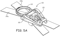
- FIGs 5A through 5B illustrations of the harness connector assembly 100 coupled to webbings 195a and 195b that are part of a safety harness system is shown.
- Webbings 195a and 195b would typically run along a back of a user from the user's shoulders to a belt webbing (not shown). In the embodiment shown, the webbings 195a and 195b cross.
- the harness connector assembly 100 is coupled at a point where the webbing 195a and 195b cross.
- the webbings 195a and 195b are routed around dorsal rivet 180 in the webbing passage 105 of the base dorsal member 102.
- the harness connector assembly 100 is mounted on the webbings 195a and 195b by first placing the crossing webbings 195a and 195b in the webbing passage 105 of the base dorsal member 102 and then inserting the dorsal rivet 180 through dorsal apertures 103a and 103b of the base dorsal member 102.
- the biasing member 182 is positioned around the dorsal rivet 180 with one of its arms received in the biasing holding member slot 113 of the base dorsal member 102. As discussed above, another arm of the biasing member 182 is received within the biasing receiving slot 123 of the sleeve portion 122 to assert a biasing force on the D-ring 120 to cause the D-ring to be at a desired position in relation to the base dorsal member 102.
- the device connector system 125 includes a first connector member 130, a swivel connector 140 and a second connector member 150.
- the first connector member 130 is shown in detail in Figures 4A and 4B .
- the first connector member 130 includes a first arm 132a and a second arm 132b that extend out on opposite ends of a mounting rod 134.
- the mounting rod 134 includes a central mounting passage 160 that passes though the entire length of the mounting rod 134.
- Each of the first arm and the second arm 132a and 132b includes a respective rivet passage 133a and 133b.
- the respective rivet passages 133a and 133b are positioned proximate terminal ends of each respective arm 132a and 132b. Moreover the rivet passages 133a and 133b are aligned.
- the first connector member 130 is pivotally coupled to the base dorsal member 102 via the dorsal rivet 180 received in the aligned rivet passages 133a and 133b of the first connector member 130.
- the swivel connector 140 of the device connector system 125 is further described.
- the swivel connector 140 is generally C-shaped having a swivel first end 140a, a swivel second end 140c and a curved swivel mid-portion 140b.
- the swivel mid-portion 140b has a width that is generally equal to the width of the mounting rod 134 of the first connector member 130.
- the curve of the swivel mid-portion 140b of the swivel connector 140 matches generally the radius of curvature of the mounting rod 134 of the first connector member 130.
- the swivel mid-portion 140b of the swivel connector 140 in this embodiment, includes slots 143a and 143b.
- swivel mid-portion 140b of the swivel connector 140 is positioned around the mounting rod 134 of the first connector member 130.
- Each of the respective swivel first and second ends 140a and 140c of the swivel connector 140 generally taper to a terminal point.
- each of the swivel first and second ends 140a and 140c of the swivel connector 140 include pivot connection apertures 141a and 141b.
- the pivot connection apertures 141a and 141b of the swivel connector 140 are aligned with each other.
- the second connector member 150 is also generally C-shaped.
- the second connector member 150 has a first end portion 150a, a second end portion 150b and a curved mid-portion 150c.
- the first and second end portions 150a and 150b terminate in a rounded configuration.
- the curved mid-portion 150c in this embodiment, includes a slot 151c.
- Each of the first end portion 150a and the second end portion 150b include a respective first and second connector aperture 151a and 151b.
- the device connector system 125 is coupled to the base dorsal member 102 of the safety harness connector assembly 100 via dorsal rivet 180 received in the rivet passages 133a and 133b of the first connector member 130.
- a connector washer 184 is received on the end portion180c of the dorsal rivet 180. Washer 184 is used to provide a surface for a rivet heading operation. The washer 184 further sets the effective length of the rivet by compressing against a rivet shoulder.
- the swivel mid-portion 140b of the swivel connector 140 is received around the mounting rod 134 of the first connector member 130.
- a connector rivet 186 that includes a head 186a, a terminal end portion 186c and a mid-shaft portion 186b couples the swivel connector 140 to the first connector member 130. As illustrated in Figure 2 , the terminal end portion 186c of the connector rivet 186 has a smaller diameter than the mid-shaft portion 186b in this example embodiment.
- the connector rivet 186 received in the pivot connection aperture 141a and 141b of the swivel connector 140 pivotally couples the swivel connector 140 to the first connector member 130.
- the swivel connector 140 pivotally rotates about the mounting rod 134 of the first connector member 130.
- the connector rivet 186 further pivotally couples the second connector member 150 to the swivel connector 140.
- the connector rivet 186 is received in the first and second connector apertures 151a and 151b of the second connecter member 150 to pivotally couple the connector member 150 to the swivel connector 140.
- the pivot connections between each of the first connector member 130 and the base dorsal member 102, the first connector member 130 and the swivel connector 140 and the swivel connector 140 and the second connector member 150 allow the device connector 125 to be positioned in different configurations for attachment of different types of devices.
- the device connector system 125 is shown being positioned in the holding tray 112 of the base dorsal member 102.
- Figure 5C illustrates the second connection member 150 being pivoted in relation to the swivel connector 140.
- a pivot axis 155 of the second connector member 150 about connector rivet 186 is generally in a perpendicular orientation in relation to a pivot axis 157 of the swivel connector 140 about the mounting rod 134 and a pivot axis 159 of the first connector member 130 about dorsal rivet 180.
- Figure 5D illustrates the safety harness connector assembly 100 coupled to a safety harness 298 donned by a user 295.
- the safety harness connector assembly 100 is coupled to webbings 195a and 195b of the safety harness 298.
- a load distribution system 296 that is coupled to the load attachment member 110 of the safety harness connector member 130.
- the load distribution system 297 transfers a load on the safety harness connector assembly 100 via an adjustable load bar 297 to a hip plate 298 that is coupled to a hip pad 293 of the safety harness 298.
- a hip webbing 299 of the safety harness 298 is routed through webbing holding members 291a and 291b in the hip plate 298.
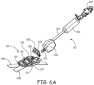
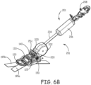
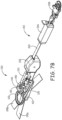
- FIG. 6A an illustration of the device connector system 125 positioned in a configuration to receive a device connector 200 is shown.
- the connector 200 is a self retracting lifeline (SRL) connector.
- Figure 6A further illustrates a SRL system 201 that includes a SRL 202, a lifeline 204, an energy absorbing system 206 and a support structure connector 208.
- a connecting ring 203 is coupled to a housing of the SRL 202.
- Figure 6B illustrates the SRL system 201 coupled to the safety harness connector assembly 100.
- the connecting ring 203 receives a mounting rod portion 205 of the SRL connector 200.
- the mounting rod portion 205 is also received within the second connection passage 170 of the second connection member 150 to pivotally couple the SRL system 201 to the webbing 195a and 195b of a safety harness.
- Figure 6B further illustrates that in this configuration, the connecting ring 203 is received in the slot 151c of the second connection member 150.
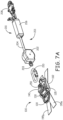
- Figure 7A is an illustration of the device connector system 125 positioned in a configuration to receive a different SRL connector 210.
- the SRL connector 210 is a carabiner.
- Figure 6B illustrates the SRL system 201 coupled to the safety harness connector assembly 100 via carabiner connector 210.
- the connecting ring 203 receives a portion of the carabiner connector 210 while another portion of the carabiner connector 210 is received within the second connection passage 170 of the second connection member 150 to pivotally couple the SRL system 201 to the webbing 195a and 195b of a safety harness.
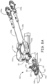
- a mounting rod portion 211 (illustrated in Figure 8A ) of SRL connector 212 is received within the first connector passage 160 of the first connector member 130 to pivotally couple the dual SRL system 214 to the webbing 195a and 195b of a safety harness.
- the device connector system 125 of the safety harness connector assembly 100 can be positioned in different configurations and has different connection points to enable the device connector system 125 to couple different type of devices and connectors to the webbings 195a and 195b of the safety harness.
Landscapes
- Health & Medical Sciences (AREA)
- General Health & Medical Sciences (AREA)
- Business, Economics & Management (AREA)
- Emergency Management (AREA)
- Emergency Lowering Means (AREA)
- Details Of Connecting Devices For Male And Female Coupling (AREA)
Applications Claiming Priority (3)
| Application Number | Priority Date | Filing Date | Title |
|---|---|---|---|
| US201562173823P | 2015-06-10 | 2015-06-10 | |
| US14/800,199 US10232199B2 (en) | 2015-06-10 | 2015-07-15 | Integral safety harness connector assembly |
| PCT/US2016/036216 WO2016200809A1 (en) | 2015-06-10 | 2016-06-07 | Integral safety harness connector assembly |
Publications (2)
| Publication Number | Publication Date |
|---|---|
| EP3307401A1 EP3307401A1 (en) | 2018-04-18 |
| EP3307401B1 true EP3307401B1 (en) | 2024-08-07 |
Family
ID=56297091
Family Applications (1)
| Application Number | Title | Priority Date | Filing Date |
|---|---|---|---|
| EP16734078.5A Active EP3307401B1 (en) | 2015-06-10 | 2016-06-07 | Integral safety harness connector assembly |
Country Status (10)
Families Citing this family (24)
| Publication number | Priority date | Publication date | Assignee | Title |
|---|---|---|---|---|
| EP2982417B1 (en) * | 2014-08-04 | 2018-07-04 | Honeywell International Inc. | Deformable energy absorber with deformation indicator |
| FR3049869B1 (fr) * | 2016-04-08 | 2018-06-22 | Zedel | Harnais |
| FR3049870A1 (fr) * | 2016-04-08 | 2017-10-13 | Zedel | Harnais |
| GB2557308B (en) * | 2016-12-06 | 2020-06-24 | Treemagineers Ltd | Harnesses |
| US10351385B2 (en) * | 2017-04-20 | 2019-07-16 | Reliance Industries, Llc | Reduced sized wearable retractable |
| WO2019012468A1 (en) * | 2017-07-13 | 2019-01-17 | 3M Innovative Properties Company | FALL ARREST DEVICE CONNECTOR |
| US10343001B2 (en) * | 2017-09-07 | 2019-07-09 | Honeywell International Inc. | Fall protection lanyard capable of direct connection to harness webbing |
| JP7245825B2 (ja) * | 2017-09-22 | 2023-03-24 | スリーエム イノベイティブ プロパティズ カンパニー | 落下抑制デバイスコネクタ |
| US11369816B2 (en) * | 2018-04-26 | 2022-06-28 | Pure Safety Group, Inc. | Positionable connector assembly |
| EP3856361A4 (en) * | 2018-09-27 | 2022-06-01 | 3M Innovative Properties Company | FALL PROTECTION SET INCLUDING SOFT ENDLESS CONNECTOR |
| US11524188B2 (en) | 2018-10-09 | 2022-12-13 | Checkmate Lifting & Safety Ltd | Tensioning device |
| TWM574499U (zh) * | 2018-11-21 | 2019-02-21 | 張恬馨 | 引導式防墜背負組件 |
| US12274899B2 (en) * | 2019-01-16 | 2025-04-15 | 3M Innovative Properties Company | Safety harness with removable rigid dorsal force-transfer member |
| GB2580674B (en) * | 2019-01-22 | 2022-12-07 | Checkmate Lifting & Safety Ltd | Coupler for a fall protection device |
| USD932109S1 (en) | 2019-01-22 | 2021-09-28 | Checkmate Lifting & Safety Ltd | Coupler for a fall protection device |
| CA3162174A1 (en) * | 2019-11-21 | 2021-05-27 | 3M Innovative Properties Company | Safety harness with self-locking dorsal brace |
| USD1032403S1 (en) * | 2019-12-20 | 2024-06-25 | Zedel | Buckle |
| WO2021246877A1 (en) * | 2020-06-02 | 2021-12-09 | Holmes Solutions Limited Partnership | Movement control system and method of use |
| US12233294B2 (en) * | 2020-09-25 | 2025-02-25 | Werner Co. | Harness adjustment device |
| US20220249887A1 (en) * | 2021-02-05 | 2022-08-11 | Werner Co. | Harness spacer, harness including the same, and method of attaching a harness spacer |
| CN115671597A (zh) * | 2021-07-23 | 2023-02-03 | 霍尼韦尔国际公司 | 与可穿戴安全带一起使用的集成个人防护设备连接器元件 |
| US20230256273A1 (en) * | 2022-02-14 | 2023-08-17 | Werner Co. | Self-retracting lifeline system |
| TWI842553B (zh) * | 2023-06-06 | 2024-05-11 | 貝加工業股份有限公司 | 旋轉錨點 |
| US20250177788A1 (en) * | 2023-12-04 | 2025-06-05 | Msa Technology, Llc | Self-retracting device harness tunnel adapter |
Citations (1)
| Publication number | Priority date | Publication date | Assignee | Title |
|---|---|---|---|---|
| US20090211849A1 (en) * | 2008-02-25 | 2009-08-27 | Hugh Smith | Systems for use with multiple safety devices and connectors for use therewith |
Family Cites Families (60)
| Publication number | Priority date | Publication date | Assignee | Title |
|---|---|---|---|---|
| US1642911A (en) | 1926-01-08 | 1927-09-20 | Carl G Thurnau | Workman's saddle belt |
| US4005904A (en) * | 1975-06-24 | 1977-02-01 | Sigmatex, A.G. | Run through bracket |
| JP2564594Y2 (ja) * | 1992-05-08 | 1998-03-09 | 藤井電工株式会社 | 墜落防止安全帯用緩衝器 |
| US5329884A (en) | 1992-06-04 | 1994-07-19 | Michael Bell | Harness with adjustable positioning pad and tool belt |
| US5531292A (en) | 1994-08-19 | 1996-07-02 | Bell; Michael | Harness with adjustable means for supporting a tool belt |
| GB2314756B (en) * | 1996-06-28 | 1999-12-15 | Graham David Roberts | Safety strap for a cable or the like |
| US6405685B1 (en) | 1996-09-24 | 2002-06-18 | Dalloz Fall Protection Investment, Inc. | Method of fabricating a safety harness |
| US5957091A (en) | 1997-11-19 | 1999-09-28 | Rose Manufacturing Company | Full body harness for fall arrest |
| US6253874B1 (en) | 1998-05-22 | 2001-07-03 | D B Industries, Inc. | Methods and apparatus for interconnecting harness straps |
| US6073724A (en) * | 1998-10-23 | 2000-06-13 | D B Industries, Inc. | Connector for a personal safety device |
| AU3485600A (en) | 1999-02-09 | 2000-08-29 | Soll Usa, Llc | Suspension harness |
| DE10011753C2 (de) * | 2000-03-13 | 2003-10-09 | Hubert Kowalewski | Klettergerät für Auf- und Abseilvorgänge |
| US6691824B2 (en) | 2000-10-13 | 2004-02-17 | Ultra-Safe, Inc. | Comfortable safety harness |
| US6739427B2 (en) | 2001-02-02 | 2004-05-25 | Bacou-Dalloz Fall Protection Investment, Inc. | Safety harness |
| US7073627B2 (en) * | 2003-09-05 | 2006-07-11 | D B Industries, Inc. | Dorsal pad assembly for use with a safety harness |
| WO2005025677A1 (en) * | 2003-09-05 | 2005-03-24 | D B Industries, Inc. | Dorsal pad assembly for use with a safety harness |
| US6971476B2 (en) | 2003-09-05 | 2005-12-06 | D B Industries, Inc. | Safety harness |
| US20050205356A1 (en) | 2004-02-25 | 2005-09-22 | Velasco Pastor Jr | Simplification of donning a safety harness and connecting a connecting element to the safety harness |
| US20050194211A1 (en) | 2004-03-05 | 2005-09-08 | O'shall James E. | Footholds for fall protection devices |
| US20050230183A1 (en) | 2004-04-16 | 2005-10-20 | Sharp C M | Tangle resistant safety harness |
| GB0410957D0 (en) * | 2004-05-15 | 2004-06-16 | Renton Julian E | Personal height rescue apparatus |
| US20060102423A1 (en) * | 2004-07-12 | 2006-05-18 | Lang Tracy H | Safety harnesses |
| US20060048723A1 (en) | 2004-09-07 | 2006-03-09 | Rohlf Bradley A | Shock absorbing safety harness |
| US7392881B1 (en) | 2004-09-09 | 2008-07-01 | Choate Gary E | Multiple stage personal fall arrest energy absorber |
| US7946387B2 (en) * | 2006-01-03 | 2011-05-24 | D B Industries, Inc. | Self-retracting lifeline |
| WO2008030552A2 (en) * | 2006-09-08 | 2008-03-13 | Sperian Fall Protection, Inc. | Safety harnesses, connective ring attachments for use in safety harnesses and back pads for use in safety harnesses |
| JP2008148803A (ja) * | 2006-12-15 | 2008-07-03 | Prop:Kk | ハーネス型安全帯 |
| US8375467B2 (en) | 2007-04-25 | 2013-02-19 | Vince Real | Safety apparatus for a person at an elevated location |
| CA2801743C (en) * | 2007-09-14 | 2015-07-21 | Nouvelle Hauteur Inc. | Emergency descent control device |
| JP5591126B2 (ja) * | 2008-02-25 | 2014-09-17 | スペリアン フォール プロテクション インコーポレイテッド | 自動引き込み命綱システム及びそのシステム用のブレーキシステム |
| CN101945688A (zh) | 2008-02-25 | 2011-01-12 | 斯博瑞安保值公司 | 能量吸收救生索系统 |
| JP5002520B2 (ja) | 2008-04-24 | 2012-08-15 | 藤井電工株式会社 | ハーネス型安全帯及び形状保持具 |
| US8091151B2 (en) | 2008-06-25 | 2012-01-10 | D B Industries, Inc. | Safety vest with integrated safety harness |
| US8245817B2 (en) | 2008-08-04 | 2012-08-21 | D B Industries, Inc. | Self-rescue safety device |
| US9737737B2 (en) * | 2008-10-23 | 2017-08-22 | Buckingham Manufacturing Company, Inc. | Body belt having added D-rings/attachment for retrofitting existing body belts |
| US8678134B2 (en) | 2008-12-26 | 2014-03-25 | Norman E. Wood | Lightweight controlled descent system with an integral reserve suspension relief strap (RSRS) |
| US8959664B2 (en) | 2009-02-09 | 2015-02-24 | D B Industries, Llc | Harness webbing protection system |
| IT1393107B1 (it) * | 2009-02-26 | 2012-04-11 | Camp Spa | Elemento per il collegamento di parti di un'imbracatura di sicurezza |
| CA2708544A1 (en) | 2009-06-25 | 2010-12-25 | Steven C. Nichols, Jr. | Methods, systems and apparatus directed to safety harnesses, and tool bags and holders, for construction workers and the like |
| US8312966B1 (en) * | 2009-09-23 | 2012-11-20 | Karl Guthrie | Beam anchor |
| US8407866B2 (en) * | 2009-10-30 | 2013-04-02 | Illinois Tool Works Inc. | Foldable attachment clip |
| CA2732587C (en) | 2010-02-24 | 2016-09-13 | Genius Happens, Llc | Wearable harness for stabilization and balance |
| US8181740B2 (en) * | 2010-02-25 | 2012-05-22 | D B Industries, Inc. | Jet bridge fall protection assembly |
| US8424638B1 (en) | 2010-04-01 | 2013-04-23 | Karl Guthrie | Swivel anchor point for fall protection |
| WO2011127109A2 (en) | 2010-04-06 | 2011-10-13 | Sperian Fall Protection Inc. | Retracting lifeline systems for use in tie-back anchoring |
| US8973705B2 (en) * | 2010-09-01 | 2015-03-10 | Climb Tech, Llc | Swivel D-ring attachment point |
| GB201019106D0 (en) * | 2010-11-12 | 2010-12-29 | Latchways Plc | Safety line connector |
| US8453794B2 (en) * | 2010-11-16 | 2013-06-04 | Jonathan J. Melic | Anchor assembly |
| KR20140101330A (ko) * | 2011-07-08 | 2014-08-19 | 칼튼 라이프 서포트 시스템즈, 아이엔씨. | 이중 해제 메커니즘을 갖는 구속 시스템 |
| US9273717B2 (en) * | 2011-10-27 | 2016-03-01 | D B Industries, Llc | Connector for lifelines |
| US9121462B2 (en) * | 2011-10-28 | 2015-09-01 | D B Industries, Llc | Self-retracting lifeline |
| US8938864B2 (en) * | 2011-10-28 | 2015-01-27 | D B Industries, Llc | Connector |
| US9265989B2 (en) * | 2011-11-18 | 2016-02-23 | D B Industries, Llc | Connecting adjustment assembly |
| US9457208B2 (en) | 2012-08-29 | 2016-10-04 | Honeywell International Inc. | Fall protection safety harness |
| US9295305B2 (en) | 2012-09-05 | 2016-03-29 | Honeywell International Inc. | D-ring with rescue attachment and lanyard attachments integrated |
| US9821178B2 (en) * | 2013-02-08 | 2017-11-21 | D B Industries, Llc | Bracket assembly |
| US9427608B2 (en) * | 2013-05-10 | 2016-08-30 | Honeywell International Inc. | Self-retracting lifeline connecting system |
| US9162090B2 (en) | 2013-08-01 | 2015-10-20 | Honeywell International Inc. | Lumbar wear-pad |
| EP2835152B1 (en) | 2013-08-05 | 2017-11-08 | Honeywell International Inc. | Dorsal wear-pad |
| US20150060195A1 (en) | 2013-09-04 | 2015-03-05 | Honeywell International Inc. | Harness with Integral Relief Loops for Suspension Trauma |
-
2015
- 2015-07-15 US US14/800,199 patent/US10232199B2/en active Active
-
2016
- 2016-06-07 JP JP2017563948A patent/JP6832295B2/ja active Active
- 2016-06-07 CN CN201680034100.3A patent/CN107787241B/zh active Active
- 2016-06-07 EP EP16734078.5A patent/EP3307401B1/en active Active
- 2016-06-07 KR KR1020187000677A patent/KR20180016544A/ko not_active Withdrawn
- 2016-06-07 RU RU2017142784A patent/RU2687813C1/ru active
- 2016-06-07 BR BR112017026661-0A patent/BR112017026661B1/pt active IP Right Grant
- 2016-06-07 CA CA2988958A patent/CA2988958A1/en not_active Abandoned
- 2016-06-07 AU AU2016274512A patent/AU2016274512B2/en active Active
- 2016-06-07 WO PCT/US2016/036216 patent/WO2016200809A1/en active Application Filing
Patent Citations (1)
| Publication number | Priority date | Publication date | Assignee | Title |
|---|---|---|---|---|
| US20090211849A1 (en) * | 2008-02-25 | 2009-08-27 | Hugh Smith | Systems for use with multiple safety devices and connectors for use therewith |
Also Published As
| Publication number | Publication date |
|---|---|
| KR20180016544A (ko) | 2018-02-14 |
| US10232199B2 (en) | 2019-03-19 |
| BR112017026661A2 (pt) | 2018-08-14 |
| RU2687813C1 (ru) | 2019-05-16 |
| US20160361577A1 (en) | 2016-12-15 |
| AU2016274512A1 (en) | 2018-01-04 |
| AU2016274512B2 (en) | 2019-01-17 |
| CN107787241B (zh) | 2021-02-05 |
| BR112017026661B1 (pt) | 2022-05-24 |
| WO2016200809A1 (en) | 2016-12-15 |
| JP2018524061A (ja) | 2018-08-30 |
| EP3307401A1 (en) | 2018-04-18 |
| CN107787241A (zh) | 2018-03-09 |
| CA2988958A1 (en) | 2016-12-15 |
| JP6832295B2 (ja) | 2021-02-24 |
Similar Documents
| Publication | Publication Date | Title |
|---|---|---|
| EP3307401B1 (en) | Integral safety harness connector assembly | |
| EP3162411A1 (en) | Protective equipment | |
| US9821178B2 (en) | Bracket assembly | |
| US10086221B2 (en) | Snap hook | |
| EP4331431A2 (en) | Breakaway keeper | |
| CN107810032B (zh) | D形环保持器组件 | |
| EP3824956B1 (en) | Apparatuses for providing fall protection systems | |
| CA2850876C (en) | A self-retracting lifeline connecting system | |
| US11369816B2 (en) | Positionable connector assembly | |
| US20100200329A1 (en) | Harness webbing protection system | |
| MX2015000802A (es) | Gancho para amarre de cuerda. | |
| US10821310B2 (en) | Harness with pivoting hip connection | |
| US20130292219A1 (en) | Energy absorber | |
| CN112770816A (zh) | 用于支撑位于高空的人的设备 | |
| EP3990129A1 (en) | Articulated harness connection arrangement with integrated attachment element | |
| CA3049147A1 (en) | Tether clip | |
| US20230026773A1 (en) | Integrated personal protective equipment connector element for use with a wearable safety harness | |
| EP4171310A1 (en) | Buckle assembly and harness comprising the same | |
| US20100294590A1 (en) | Method, Apparatus, and Arrangement for a Lifeline System | |
| EP2094127B1 (en) | Harness with an arrangement for carrying a hand-held motor-driven tool | |
| EP3020297A1 (en) | Suspending device for trousers | |
| EP1980707A1 (en) | Foldable ladder with flexible handle | |
| KR20070021104A (ko) | 안전기구와 이용되는 척추용 패드조립체 |
Legal Events
| Date | Code | Title | Description |
|---|---|---|---|
| STAA | Information on the status of an ep patent application or granted ep patent |
Free format text: STATUS: THE INTERNATIONAL PUBLICATION HAS BEEN MADE |
|
| PUAI | Public reference made under article 153(3) epc to a published international application that has entered the european phase |
Free format text: ORIGINAL CODE: 0009012 |
|
| STAA | Information on the status of an ep patent application or granted ep patent |
Free format text: STATUS: REQUEST FOR EXAMINATION WAS MADE |
|
| 17P | Request for examination filed |
Effective date: 20180108 |
|
| AK | Designated contracting states |
Kind code of ref document: A1 Designated state(s): AL AT BE BG CH CY CZ DE DK EE ES FI FR GB GR HR HU IE IS IT LI LT LU LV MC MK MT NL NO PL PT RO RS SE SI SK SM TR |
|
| AX | Request for extension of the european patent |
Extension state: BA ME |
|
| DAV | Request for validation of the european patent (deleted) | ||
| DAX | Request for extension of the european patent (deleted) | ||
| STAA | Information on the status of an ep patent application or granted ep patent |
Free format text: STATUS: EXAMINATION IS IN PROGRESS |
|
| 17Q | First examination report despatched |
Effective date: 20210421 |
|
| STAA | Information on the status of an ep patent application or granted ep patent |
Free format text: STATUS: EXAMINATION IS IN PROGRESS |
|
| GRAP | Despatch of communication of intention to grant a patent |
Free format text: ORIGINAL CODE: EPIDOSNIGR1 |
|
| STAA | Information on the status of an ep patent application or granted ep patent |
Free format text: STATUS: GRANT OF PATENT IS INTENDED |
|
| INTG | Intention to grant announced |
Effective date: 20240319 |
|
| GRAS | Grant fee paid |
Free format text: ORIGINAL CODE: EPIDOSNIGR3 |
|
| GRAA | (expected) grant |
Free format text: ORIGINAL CODE: 0009210 |
|
| STAA | Information on the status of an ep patent application or granted ep patent |
Free format text: STATUS: THE PATENT HAS BEEN GRANTED |
|
| AK | Designated contracting states |
Kind code of ref document: B1 Designated state(s): AL AT BE BG CH CY CZ DE DK EE ES FI FR GB GR HR HU IE IS IT LI LT LU LV MC MK MT NL NO PL PT RO RS SE SI SK SM TR |
|
| REG | Reference to a national code |
Ref country code: GB Ref legal event code: FG4D |
|
| REG | Reference to a national code |
Ref country code: CH Ref legal event code: EP |
|
| REG | Reference to a national code |
Ref country code: IE Ref legal event code: FG4D |
|
| REG | Reference to a national code |
Ref country code: DE Ref legal event code: R096 Ref document number: 602016088763 Country of ref document: DE |
|
| P01 | Opt-out of the competence of the unified patent court (upc) registered |
Free format text: CASE NUMBER: APP_44301/2024 Effective date: 20240730 |
|
| REG | Reference to a national code |
Ref country code: LT Ref legal event code: MG9D |
|
| REG | Reference to a national code |
Ref country code: NL Ref legal event code: MP Effective date: 20240807 |
|
| PG25 | Lapsed in a contracting state [announced via postgrant information from national office to epo] |
Ref country code: NO Free format text: LAPSE BECAUSE OF FAILURE TO SUBMIT A TRANSLATION OF THE DESCRIPTION OR TO PAY THE FEE WITHIN THE PRESCRIBED TIME-LIMIT Effective date: 20241107 |
|
| REG | Reference to a national code |
Ref country code: AT Ref legal event code: MK05 Ref document number: 1710302 Country of ref document: AT Kind code of ref document: T Effective date: 20240807 |
|
| PG25 | Lapsed in a contracting state [announced via postgrant information from national office to epo] |
Ref country code: PL Free format text: LAPSE BECAUSE OF FAILURE TO SUBMIT A TRANSLATION OF THE DESCRIPTION OR TO PAY THE FEE WITHIN THE PRESCRIBED TIME-LIMIT Effective date: 20240807 Ref country code: FI Free format text: LAPSE BECAUSE OF FAILURE TO SUBMIT A TRANSLATION OF THE DESCRIPTION OR TO PAY THE FEE WITHIN THE PRESCRIBED TIME-LIMIT Effective date: 20240807 Ref country code: PT Free format text: LAPSE BECAUSE OF FAILURE TO SUBMIT A TRANSLATION OF THE DESCRIPTION OR TO PAY THE FEE WITHIN THE PRESCRIBED TIME-LIMIT Effective date: 20241209 Ref country code: GR Free format text: LAPSE BECAUSE OF FAILURE TO SUBMIT A TRANSLATION OF THE DESCRIPTION OR TO PAY THE FEE WITHIN THE PRESCRIBED TIME-LIMIT Effective date: 20241108 Ref country code: NL Free format text: LAPSE BECAUSE OF FAILURE TO SUBMIT A TRANSLATION OF THE DESCRIPTION OR TO PAY THE FEE WITHIN THE PRESCRIBED TIME-LIMIT Effective date: 20240807 |
|
| PG25 | Lapsed in a contracting state [announced via postgrant information from national office to epo] |
Ref country code: BG Free format text: LAPSE BECAUSE OF FAILURE TO SUBMIT A TRANSLATION OF THE DESCRIPTION OR TO PAY THE FEE WITHIN THE PRESCRIBED TIME-LIMIT Effective date: 20240807 |
|
| PG25 | Lapsed in a contracting state [announced via postgrant information from national office to epo] |
Ref country code: LV Free format text: LAPSE BECAUSE OF FAILURE TO SUBMIT A TRANSLATION OF THE DESCRIPTION OR TO PAY THE FEE WITHIN THE PRESCRIBED TIME-LIMIT Effective date: 20240807 |
|
| PG25 | Lapsed in a contracting state [announced via postgrant information from national office to epo] |
Ref country code: AT Free format text: LAPSE BECAUSE OF FAILURE TO SUBMIT A TRANSLATION OF THE DESCRIPTION OR TO PAY THE FEE WITHIN THE PRESCRIBED TIME-LIMIT Effective date: 20240807 Ref country code: IS Free format text: LAPSE BECAUSE OF FAILURE TO SUBMIT A TRANSLATION OF THE DESCRIPTION OR TO PAY THE FEE WITHIN THE PRESCRIBED TIME-LIMIT Effective date: 20241207 |
|
| PG25 | Lapsed in a contracting state [announced via postgrant information from national office to epo] |
Ref country code: HR Free format text: LAPSE BECAUSE OF FAILURE TO SUBMIT A TRANSLATION OF THE DESCRIPTION OR TO PAY THE FEE WITHIN THE PRESCRIBED TIME-LIMIT Effective date: 20240807 |
|
| PG25 | Lapsed in a contracting state [announced via postgrant information from national office to epo] |
Ref country code: ES Free format text: LAPSE BECAUSE OF FAILURE TO SUBMIT A TRANSLATION OF THE DESCRIPTION OR TO PAY THE FEE WITHIN THE PRESCRIBED TIME-LIMIT Effective date: 20240807 Ref country code: RS Free format text: LAPSE BECAUSE OF FAILURE TO SUBMIT A TRANSLATION OF THE DESCRIPTION OR TO PAY THE FEE WITHIN THE PRESCRIBED TIME-LIMIT Effective date: 20241107 |
|
| PG25 | Lapsed in a contracting state [announced via postgrant information from national office to epo] |
Ref country code: RS Free format text: LAPSE BECAUSE OF FAILURE TO SUBMIT A TRANSLATION OF THE DESCRIPTION OR TO PAY THE FEE WITHIN THE PRESCRIBED TIME-LIMIT Effective date: 20241107 Ref country code: PT Free format text: LAPSE BECAUSE OF FAILURE TO SUBMIT A TRANSLATION OF THE DESCRIPTION OR TO PAY THE FEE WITHIN THE PRESCRIBED TIME-LIMIT Effective date: 20241209 Ref country code: PL Free format text: LAPSE BECAUSE OF FAILURE TO SUBMIT A TRANSLATION OF THE DESCRIPTION OR TO PAY THE FEE WITHIN THE PRESCRIBED TIME-LIMIT Effective date: 20240807 Ref country code: NO Free format text: LAPSE BECAUSE OF FAILURE TO SUBMIT A TRANSLATION OF THE DESCRIPTION OR TO PAY THE FEE WITHIN THE PRESCRIBED TIME-LIMIT Effective date: 20241107 Ref country code: NL Free format text: LAPSE BECAUSE OF FAILURE TO SUBMIT A TRANSLATION OF THE DESCRIPTION OR TO PAY THE FEE WITHIN THE PRESCRIBED TIME-LIMIT Effective date: 20240807 Ref country code: LV Free format text: LAPSE BECAUSE OF FAILURE TO SUBMIT A TRANSLATION OF THE DESCRIPTION OR TO PAY THE FEE WITHIN THE PRESCRIBED TIME-LIMIT Effective date: 20240807 Ref country code: IS Free format text: LAPSE BECAUSE OF FAILURE TO SUBMIT A TRANSLATION OF THE DESCRIPTION OR TO PAY THE FEE WITHIN THE PRESCRIBED TIME-LIMIT Effective date: 20241207 Ref country code: HR Free format text: LAPSE BECAUSE OF FAILURE TO SUBMIT A TRANSLATION OF THE DESCRIPTION OR TO PAY THE FEE WITHIN THE PRESCRIBED TIME-LIMIT Effective date: 20240807 Ref country code: GR Free format text: LAPSE BECAUSE OF FAILURE TO SUBMIT A TRANSLATION OF THE DESCRIPTION OR TO PAY THE FEE WITHIN THE PRESCRIBED TIME-LIMIT Effective date: 20241108 Ref country code: FI Free format text: LAPSE BECAUSE OF FAILURE TO SUBMIT A TRANSLATION OF THE DESCRIPTION OR TO PAY THE FEE WITHIN THE PRESCRIBED TIME-LIMIT Effective date: 20240807 Ref country code: ES Free format text: LAPSE BECAUSE OF FAILURE TO SUBMIT A TRANSLATION OF THE DESCRIPTION OR TO PAY THE FEE WITHIN THE PRESCRIBED TIME-LIMIT Effective date: 20240807 Ref country code: BG Free format text: LAPSE BECAUSE OF FAILURE TO SUBMIT A TRANSLATION OF THE DESCRIPTION OR TO PAY THE FEE WITHIN THE PRESCRIBED TIME-LIMIT Effective date: 20240807 Ref country code: AT Free format text: LAPSE BECAUSE OF FAILURE TO SUBMIT A TRANSLATION OF THE DESCRIPTION OR TO PAY THE FEE WITHIN THE PRESCRIBED TIME-LIMIT Effective date: 20240807 |
|
| PG25 | Lapsed in a contracting state [announced via postgrant information from national office to epo] |
Ref country code: DK Free format text: LAPSE BECAUSE OF FAILURE TO SUBMIT A TRANSLATION OF THE DESCRIPTION OR TO PAY THE FEE WITHIN THE PRESCRIBED TIME-LIMIT Effective date: 20240807 Ref country code: RO Free format text: LAPSE BECAUSE OF FAILURE TO SUBMIT A TRANSLATION OF THE DESCRIPTION OR TO PAY THE FEE WITHIN THE PRESCRIBED TIME-LIMIT Effective date: 20240807 Ref country code: SM Free format text: LAPSE BECAUSE OF FAILURE TO SUBMIT A TRANSLATION OF THE DESCRIPTION OR TO PAY THE FEE WITHIN THE PRESCRIBED TIME-LIMIT Effective date: 20240807 |
|
| PG25 | Lapsed in a contracting state [announced via postgrant information from national office to epo] |
Ref country code: EE Free format text: LAPSE BECAUSE OF FAILURE TO SUBMIT A TRANSLATION OF THE DESCRIPTION OR TO PAY THE FEE WITHIN THE PRESCRIBED TIME-LIMIT Effective date: 20240807 |
|
| PG25 | Lapsed in a contracting state [announced via postgrant information from national office to epo] |
Ref country code: CZ Free format text: LAPSE BECAUSE OF FAILURE TO SUBMIT A TRANSLATION OF THE DESCRIPTION OR TO PAY THE FEE WITHIN THE PRESCRIBED TIME-LIMIT Effective date: 20240807 |
|
| PG25 | Lapsed in a contracting state [announced via postgrant information from national office to epo] |
Ref country code: SK Free format text: LAPSE BECAUSE OF FAILURE TO SUBMIT A TRANSLATION OF THE DESCRIPTION OR TO PAY THE FEE WITHIN THE PRESCRIBED TIME-LIMIT Effective date: 20240807 |
|
| REG | Reference to a national code |
Ref country code: DE Ref legal event code: R097 Ref document number: 602016088763 Country of ref document: DE |
|
| PLBE | No opposition filed within time limit |
Free format text: ORIGINAL CODE: 0009261 |
|
| STAA | Information on the status of an ep patent application or granted ep patent |
Free format text: STATUS: NO OPPOSITION FILED WITHIN TIME LIMIT |
|
| PGFP | Annual fee paid to national office [announced via postgrant information from national office to epo] |
Ref country code: DE Payment date: 20250520 Year of fee payment: 10 |
|
| PGFP | Annual fee paid to national office [announced via postgrant information from national office to epo] |
Ref country code: GB Payment date: 20250520 Year of fee payment: 10 |
|
| 26N | No opposition filed |
Effective date: 20250508 |
|
| PGFP | Annual fee paid to national office [announced via postgrant information from national office to epo] |
Ref country code: FR Payment date: 20250520 Year of fee payment: 10 |