EP3307152B1 - Multivektorielle patientenkontaktschnittstelle - Google Patents
Multivektorielle patientenkontaktschnittstelle Download PDFInfo
- Publication number
- EP3307152B1 EP3307152B1 EP16808267.5A EP16808267A EP3307152B1 EP 3307152 B1 EP3307152 B1 EP 3307152B1 EP 16808267 A EP16808267 A EP 16808267A EP 3307152 B1 EP3307152 B1 EP 3307152B1
- Authority
- EP
- European Patent Office
- Prior art keywords
- conductive
- patient
- patient contact
- contact
- electrode pad
- Prior art date
- Legal status (The legal status is an assumption and is not a legal conclusion. Google has not performed a legal analysis and makes no representation as to the accuracy of the status listed.)
- Active
Links
Images





Classifications
-
- A—HUMAN NECESSITIES
- A61—MEDICAL OR VETERINARY SCIENCE; HYGIENE
- A61N—ELECTROTHERAPY; MAGNETOTHERAPY; RADIATION THERAPY; ULTRASOUND THERAPY
- A61N1/00—Electrotherapy; Circuits therefor
- A61N1/02—Details
- A61N1/04—Electrodes
- A61N1/0404—Electrodes for external use
- A61N1/0472—Structure-related aspects
-
- A—HUMAN NECESSITIES
- A61—MEDICAL OR VETERINARY SCIENCE; HYGIENE
- A61N—ELECTROTHERAPY; MAGNETOTHERAPY; RADIATION THERAPY; ULTRASOUND THERAPY
- A61N1/00—Electrotherapy; Circuits therefor
- A61N1/18—Applying electric currents by contact electrodes
- A61N1/32—Applying electric currents by contact electrodes alternating or intermittent currents
- A61N1/38—Applying electric currents by contact electrodes alternating or intermittent currents for producing shock effects
- A61N1/39—Heart defibrillators
- A61N1/3918—Heart defibrillators characterised by shock pathway, e.g. by electrode configuration
-
- A—HUMAN NECESSITIES
- A61—MEDICAL OR VETERINARY SCIENCE; HYGIENE
- A61N—ELECTROTHERAPY; MAGNETOTHERAPY; RADIATION THERAPY; ULTRASOUND THERAPY
- A61N1/00—Electrotherapy; Circuits therefor
- A61N1/02—Details
- A61N1/04—Electrodes
- A61N1/0404—Electrodes for external use
- A61N1/0408—Use-related aspects
- A61N1/046—Specially adapted for shock therapy, e.g. defibrillation
-
- A—HUMAN NECESSITIES
- A61—MEDICAL OR VETERINARY SCIENCE; HYGIENE
- A61N—ELECTROTHERAPY; MAGNETOTHERAPY; RADIATION THERAPY; ULTRASOUND THERAPY
- A61N1/00—Electrotherapy; Circuits therefor
- A61N1/02—Details
- A61N1/04—Electrodes
- A61N1/0404—Electrodes for external use
- A61N1/0472—Structure-related aspects
- A61N1/0476—Array electrodes (including any electrode arrangement with more than one electrode for at least one of the polarities)
-
- A—HUMAN NECESSITIES
- A61—MEDICAL OR VETERINARY SCIENCE; HYGIENE
- A61N—ELECTROTHERAPY; MAGNETOTHERAPY; RADIATION THERAPY; ULTRASOUND THERAPY
- A61N1/00—Electrotherapy; Circuits therefor
- A61N1/18—Applying electric currents by contact electrodes
- A61N1/32—Applying electric currents by contact electrodes alternating or intermittent currents
- A61N1/38—Applying electric currents by contact electrodes alternating or intermittent currents for producing shock effects
- A61N1/39—Heart defibrillators
- A61N1/3906—Heart defibrillators characterised by the form of the shockwave
-
- A—HUMAN NECESSITIES
- A61—MEDICAL OR VETERINARY SCIENCE; HYGIENE
- A61N—ELECTROTHERAPY; MAGNETOTHERAPY; RADIATION THERAPY; ULTRASOUND THERAPY
- A61N1/00—Electrotherapy; Circuits therefor
- A61N1/18—Applying electric currents by contact electrodes
- A61N1/32—Applying electric currents by contact electrodes alternating or intermittent currents
- A61N1/38—Applying electric currents by contact electrodes alternating or intermittent currents for producing shock effects
- A61N1/39—Heart defibrillators
- A61N1/3925—Monitoring; Protecting
-
- A—HUMAN NECESSITIES
- A61—MEDICAL OR VETERINARY SCIENCE; HYGIENE
- A61N—ELECTROTHERAPY; MAGNETOTHERAPY; RADIATION THERAPY; ULTRASOUND THERAPY
- A61N1/00—Electrotherapy; Circuits therefor
- A61N1/18—Applying electric currents by contact electrodes
- A61N1/32—Applying electric currents by contact electrodes alternating or intermittent currents
- A61N1/36—Applying electric currents by contact electrodes alternating or intermittent currents for stimulation
- A61N1/36014—External stimulators, e.g. with patch electrodes
- A61N1/36025—External stimulators, e.g. with patch electrodes for treating a mental or cerebral condition
Definitions
- a defibrillator uses electrical shocks to restore the proper functioning of the heart.
- a crucial component of the success or failure of defibrillation, however, is time. Ideally, a victim should be defibrillated immediately upon suffering a Sudden Cardiac Arrest, as the victim's chances of survival dwindle rapidly for every minute without treatment.
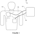
- FIG. 1 illustrates a conventional AED 100, which includes a base unit 102 and two pads 104. Sometimes paddles with handles are used instead of the pads 104. The pads 104 are connected to the base unit 102 using electrical cables 106.
- a typical protocol for using the AED 100 is as follows. Initially, the person who has suffered from sudden cardiac arrest is placed on the floor. Clothing is removed to reveal the person's chest 108. The pads 104 are applied to appropriate locations on the chest 108, as illustrated in figure 1 . The electrical system within the base unit 100 generates a high voltage between the two pads 104, which delivers an electrical shock to the person. Ideally, the shock restores a normal cardiac rhythm. In some cases, multiple shocks are required.
- An additional challenge is that a sudden cardiac arrest may take place anywhere. People often spend time away from public facilities and their homes. For example, a sudden cardiac arrest could strike someone while biking in the hills, skiing on the mountains, strolling along the beach, or jogging on a dirt trail.
- an improved AED design would be compact, light, and resistant to the elements and easily attached or detached from one's body.
- the typical AED design illustrated in Figure 8 which includes a sizable console or power unit whose form factor is similar to that of a laptop or backpack, seems less than ideal for the outdoors and other rigorous environments.
- New and improved designs are allowing AEDs to become ultra-portable and hence to able to be easily carried by an at-risk person as they go about all of their daily activities and thus are able to be close at hand when a sudden cardiac arrest strikes outside of a hospital environment or a high traffic public area with a Public Access Defibrillator.
- WCD Wearable Cardioverter Defibrillator
- the WCD is an external device worn by an at-risk person which continuously monitors their heart rhythm to identify the occurrence of an arrhythmia, to then correctly identify the type of arrhythmia involved and then to automatically apply the therapeutic action required for the type of arrhythmia identified, whether this be cardioversion or defibrillation.
- These devices are most frequently used for patients who have been identified as potentially requiring an ICD and to effectively protect them during the two to six month medical evaluation period before a final decision is made and they are officially cleared for, or denied, an ICD.
- External Defibrillators and Automated External Defibrillators on the market today make use of either rigid paddles that must be held in place on the patient's body or else flexible electrode pads (made of conductive foil and foam) which are stuck to the patient's skin.
- the current external defibrillators that have rigid paddle bases do not conform to the curvatures of the patient's body at the locations on the body where the paddles must be placed in order to be effective.
- the operators of these devices must apply a good amount of contact force to make physical contact across the paddle's patient contact interface and must maintain this force to maximize the surface area in contact with the patient for the sensing and reading of the heart rhythm in order that the device can detect the presence of a faulty rhythm, or arrhythmia, such as Ventricular Fibrillation or Ventricular Tachycardia so as to instruct / initiate or signal the external defibrillator to deliver the life saving therapeutic defibrillation shock pulse.
- arrhythmia such as Ventricular Fibrillation or Ventricular Tachycardia so as to instruct / initiate or signal the external defibrillator to deliver the life saving therapeutic defibrillation shock pulse.
- the operator must also continue holding the required contact force while the device delivers the chosen therapeutic action (shock or no shock).
- US 2001/027270 A1 discloses a bio-electic interface adapter with at least two large area defibrilation electrodes and sufficient smaller precordial electrodes present therein to allow standard twelve lead ECG monitoring.
- the defibrillation electrodes can be affixed to the bioelectric interface via perforations, or by a functionally similar approach, to allow easy detachment in use.
- the bioelectric interface adaptor preferably has an undulated outer edge geometry, and provides electrodes for forming limb leads, optionally allowing use of the defibrillation electrodes as Right Arm and Left Leg electrodes. Limb lead forming electrodes are preferable affixed via perforations, or by a functionally similar approach, to allow easy detachment and deployment to conventional limb electrode locations, in use.
- US 6 714 824 B1 discloses that electrodes are capable of delivering synchronized cardioversion and pacing energy pulses as well as defibrillation energy pulses to a patient.
- the electrodes are also appropriate for use with an automatic or semi-automatic external defibrillator (AED) as well as defibrillators capable of cardioversion and manual defibrillators.
- AED automatic or semi-automatic external defibrillator
- the electrodes have a plurality of conductors sized for delivering electrotherapy to patients of different sizes. Preferably, conductors can be used singly or in combination for therapy.
- the electrodes may also be separated to form electrodes of smaller dimension for application to a smaller patient.
- This disclosure also allows for the static or dynamic configuration of one-to-many and many-to-one shock vector arrangements as an alternate or additional method of enhancing the overall percentage of cardiac tissue that is successfully defibrillated or cardioverted.
- This approach can also be used for delivering electrical pulses, at any level of energy, in other therapeutic and clinical areas outside of cardiac stimulation in order to cause a specific therapeutic outcome in a patient such as in the fields of neurological stimulation, gastrointestinal stimulation or the stimulation of specific internal organs or nerve systems within a patient's body.
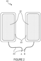
- Figure 2 illustrates a pair of standard single vector electrode pads (200), used by the majority of current external defibrillators and cardioverters, exhibiting the standard adhesive and conductive electrode patient-facing surfaces, one on each of the single vector electrode pads (201) and the non-conductive adhesive mounted on the electrode pad backing material which surrounds (202) each of the adhesive and conductive electrode surfaces (201) and the electrical leads from the central defibrillator unit to each of the conductive electrode pads (203).
- Figure 3 illustrates an embodiment with a pair of multi-pad multi-vector electrode pads (300).
- the multiple adhesive and conductive electrode patient-facing surfaces (301) are surrounded by areas of non-conductive adhesive (302) which are mounted on the non-conductive electrode pad backing material/substrate (304) so that each electrode patient-facing surface (301) is electrically isolated from the other electrode patient-facing surfaces.
- This electrode pad backing material (304) in some embodiments is able to be folded along the axis between the immediately adjacent adhesive and conductive electrode patient-facing surfaces.
- Each of the adhesive and conductive electrode patient-facing surfaces (301) is connected to an electrical lead (303) that connects back to the defibrillator.
- Each of these electrical leads is a distinctly separate electrical pathway (as shown by 303A, 303B, 303C and 303D) and they can be used separately or in tandem to deliver pulses or the separate phases of pulses in any combination of shock vectors. In some embodiments this coordination is performed by static wiring and in other embodiments it is implemented via dynamic switching within the defibrillator or within a separate module that is located between the electrode pads and the defibrillator unit. In some embodiments the electrical leads (303) are directly integrated into a housing on the non-patient facing side of the electrode pads.
- each of the electrode pads may have a single main adhesive and conductive electrode patient-facing surface (301) with a surrounding area of non-conductive adhesive (302) and the non-conductive electrode pad backing material (304) so that each electrode pad is separate.
- the electrode pad backing material/substrate may be flexible and thus capable of providing optimal contact with an uneven contact surface when the multi-vector patient contact surface is placed against the uneven contact surface.
- the electrode pad backing material/substrate and patient contact surface may conform to the uneven contact surface, such as a body part of a patient and the like.
- the electrode pad backing material/substrate may also be made of a rigid material.
- the conductive electrode patient-facing surface may be an electrode as shown in the figures.
- the conductive electrode patient-facing surface may also be a sensor that may be of a type described.
- the patient contacts may be two or more electrodes and one or more sensors.
- the one or more sensors may be arranged in the configuration separately from the two or more electrodes and/or the one or more sensors may be arranged in the configuration intermixed with the two or more electrodes.
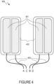
- Figure 4 illustrates a pair of split vertical multi-vector electrode pads (400).
- the multiple adhesive and conductive electrode patient-facing surface portions (401) are surrounded by areas of non-conductive adhesive (402) which are mounted on the electrode pad backing material so that each portion 401 is electrically isolated.
- Each of the adhesive and conductive electrode patient-facing surface portions (401) is connected to an electrical lead (403) that connects back to the defibrillator.
- Each of these electrical leads is a distinctly separate electrical pathway (as shown here by 403A, 403B, 403C and 403D) and they can be used separately or coordinated in groupings to deliver pulses or the separate phases of pulses in any combination of individual or simultaneous vectors.
- this coordination is performed by static wiring and in other embodiments it is implemented via dynamic switching within the defibrillator or within a separate module that is located between the electrode pads and the defibrillator unit.
- the electrical leads (403) are directly integrated into a housing on the non-patient facing side of the electrode pads. In the example in Figure 4 , four electrodes may be fit into the area of two electrode pads.
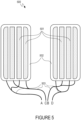
- Figure 5 illustrates a pair of multi-split vertical multi-vector electrode pads (500).
- the multiple adhesive and conductive electrode patient-facing surface portions (501) are surrounded by areas of non-conductive adhesive (502) which are mounted on the electrode pad backing material so that each portion 501 is electrically isolated.
- Each of the adhesive and conductive electrode patient-facing surface portions (501) is connected to an electrical lead (503) that connects back to the defibrillator.
- Each of these electrical leads is a distinctly separate electrical pathway (for this embodiment they are shown grouped into pairs by 503A, 503B, 503C and 503D) and they can be used separately or in tandem to deliver pulses or the separate phases of pulses in any combination of vectors.
- this coordination/pairing of the electrical leads is performed by static wiring and in other embodiments it is implemented via dynamic switching within the defibrillator or within a separate module that is located between the electrode pads and the defibrillator unit.
- the electrical leads (503) are directly integrated into a housing on the non-patient facing side of the electrode pads.
- Figure 6 illustrates a pair of split diagonal multi-vector electrode pads (600).
- the multiple adhesive and conductive electrode patient-facing surface portions (601) are surrounded by areas of non-conductive adhesive (602) which are mounted on the electrode pad backing material so that each portion 601 is electrically isolated.
- Each of the adhesive and conductive electrode patient-facing surface portions (601) is connected to an electrical lead (603) that connects back to the defibrillator.
- Each of these electrical leads is a distinctly separate electrical pathway (as shown here by 603A, 603B, 603C and 603D) and they can be used separately or coordinated in groupings to deliver pulses or the separate phases of pulses in any combination of individual or simultaneous vectors.
- this coordination/pairing of the electrical leads is performed by static wiring and in other embodiments it is implemented via dynamic switching within the defibrillator or within a separate module that is located between the electrode pads and the defibrillator unit.
- the electrical leads (703) are directly integrated into a housing on the non-patient facing side of the electrode pads.
- Figure 8 illustrates a pair of split non-linear multi-vector electrode pads (800).
- the multiple adhesive and conductive electrode patient-facing surface portions (801) are surrounded by areas of non-conductive adhesive (802) which are mounted on the electrode pad backing material so that each portion 801 is electrically isolated.
- Each of the adhesive and conductive electrode patient-facing surface portions (801) is connected to an electrical lead (803) that connects back to the defibrillator.
- Each of these electrical leads is a distinctly separate electrical pathway (as shown here by 803A, 803B, 803C and 803D) and they can be used separately or coordinated in groupings to deliver pulses or the separate phases of pulses in any combination of individual or simultaneous vectors.
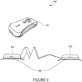
- FIG. 9 illustrates an example of a novel compact external defibrillator (900).
- the device is shown in a non deployed form (901) with the electrode pads stored internally.
- the device assumes the form of two connected housings (902) each of which has an electrode pad on the patient-facing side (908), shown here facing down.
- the device circuitry contained within the housings on the non-patient-facing sides it is plain to see that external electrical leads are not required because the electrical leads are directly integrated through the electrode pad backing material and into the housings on the non-patient facing sides of the electrode pads.
- Figure 11 illustrates some of range of the potential placement positions on a patient of some multi-pad multi-vector electrode pads.
- the pads shown (1104A, 1104B, 1104C, 1104D) are an embodiment of the multi-pad multi-vector electrode pads shown in Figure 3 , where the individual electrode pads involved are able to be separately placed and are not linked together into pairs of electrode pads via a common piece of electrode pad non-conductive backing material (304). Hence it is possible for the four pads shown in this embodiment (1104A, 1104B, 1104C, 1104D) to be each be placed in separate locations on the patient.
- Figure 12 illustrates placement positions on a patient of a pair of dual-pad multi-vector electrode pads.
- the pads shown (1204 A,C and 1204 B,D) are an embodiment of the multi-pad multi-vector electrode pads shown in Figure 3 , where the individual electrode pads involved are linked together in pairs and joined by a common piece of electrode pad non-conductive backing material (304).
- the two pairs of pads shown in this embodiment (1204 A,C and 1204 B,D) to be each placed in separate locations on the patient.
- the locations shown in Figure 12 are: on the side of the torso just under the left arm (1204 A,C), and on the side of the torso just under the right arm (1204 B,D).
- any other therapeutically efficacious location on the patient's torse, limbs or head can be used instead or in addition to the locations shown here, according to the shock vectors required.
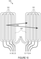
- the shock vectors can be on a one-to-one, one-to-many, many-to-one, or many-to-many basis according to the therapeutic need or clinical preference.
- these multi-vector electrode pads are integrated into an ECG sensing garment, such as a wearable shirt.
- Electrodes 1402 may be externally visible on the harness or equivalent wearable system or else they may be directly incorporated into the harness or equivalent wearable system and hence only internal to it, or else the harness or equivalent wearable system incorporates a mixture of the two approaches.
- the electrodes can be dual stimulation and sensing electrodes in addition to purely stimulation electrodes, or a mixture of the two types.
- this approach includes various embodiments intended for various specific uses such as seatbelts or other transportation and safety harness systems where the prompt treatment of a patient cannot be easily facilitated by a third party and hence an in-built capability is required.
- the multi-vector patient contact interface described in this document may be placed onto a body of a patient and may be used, for example, to sense the heartbeat of the patient and then deliver a therapeutic pulse to the patient for defibrillation for example.
- the multi-vector patient contact interface may also be used to deliver other types of treatments of varying energies and durations to the patient.
- the multi-vector patient contact interface may also be used to sense a characteristic of the patient, such as a heartbeat or pulse and the like.
- the multi-vector patient contact interface may also be used to both sense a characteristic of the patient and deliver a treatment to the patient when the embodiment of the multi-vector patient contact interface makes use of both sensors and electrodes.
- the systems described above may be used to deliver a pulse waveform to a patient using the patient contacts.
- An example of the pulse generator and waveforms that may be used with the systems are described in co-pending patent application serial numbers 14/303,541 filed on June 12, 2014 , 14/661,949 filed March 18, 2015 and 14/662,137 filed March 18, 2015 .
- the one or more multi-vector patient contact interfaces may be attached to a patient and a medical device capable of generating a pulse waveform may be connected to the electrical leads that are connected to the one or more multi-vector patient contact interfaces.
- a pulse waveform may be delivered from the medical device to the patient via the one or more multi-vector patient contact interfaces.
- the shock vector may be a path from one-electrode-to-one-electrode, a path from one-electrode-to-many-electrodes, a path from many-electrodes-to-one-electrode and a path from many-electrodes-to-many-electrodes.
Landscapes
- Health & Medical Sciences (AREA)
- Life Sciences & Earth Sciences (AREA)
- Public Health (AREA)
- Veterinary Medicine (AREA)
- Biomedical Technology (AREA)
- Nuclear Medicine, Radiotherapy & Molecular Imaging (AREA)
- Radiology & Medical Imaging (AREA)
- Engineering & Computer Science (AREA)
- Animal Behavior & Ethology (AREA)
- General Health & Medical Sciences (AREA)
- Heart & Thoracic Surgery (AREA)
- Cardiology (AREA)
- Electrotherapy Devices (AREA)
- Child & Adolescent Psychology (AREA)
- Developmental Disabilities (AREA)
- Hospice & Palliative Care (AREA)
- Neurology (AREA)
- Psychiatry (AREA)
- Psychology (AREA)
- Social Psychology (AREA)
- Biophysics (AREA)
Claims (8)
- Eine Multivektor-Patientenkontaktschnittstelle, umfassend:ein erstes Elektrodenkissen (300) und ein zweites Elektrodenkissen (300);wobei das erste und das zweite Elektrodenkissen (300) jeweils ein nicht leitfähiges Substrat (304) aufweisen,zwei oder mehr nicht leitfähige adhäsive Regionen (302), die auf dem nicht leitfähigen Substrat (304) gebildet sind, und mindestens einen ersten leitfähigen Patientenkontakt (301) und einen zweiten leitfähigen Patientenkontakt (301), wobei mindestens ein Patientenkontakt (301) an jeder nicht leitfähigen adhäsiven Region (302) haftet und von dieser umgeben ist;zwei oder mehr elektrische Leitungen (303), wobei jeder leitfähige Patientenkontakt (301) elektrisch mit einer unterschiedlichen elektrischen Leitung (303) verbunden ist;wobei jeder leitfähige Patientenkontakt (301) auf jedem Elektrodenkissen (300) von den anderen leitfähigen Patientenkontakten (301) auf demselben Elektrodenkissen (300) durch das nicht leitfähige Substrat (304) und die adhäsiven Regionen (302) elektrisch isoliert ist;wobei der erste leitfähige Patientenkontakt (301) und die elektrische Leitung (303), die mit dem ersten leitfähigen Patientenkontakt (301) des ersten Elektrodenkissens (300) verbunden ist, einen separaten Schockvektor mit dem ersten leitfähigen Patientenkontakt (301) und der elektrischen Leitung (303) bildet, die mit dem ersten leitfähigen Patientenkontakt (301) des zweiten Elektrodenkissens (300) verbunden ist, und der zweite leitfähige Patientenkontakt (301) und die elektrische Leitung (303), die mit dem zweiten leitfähigen Patientenkontakt (301) des ersten Elektrodenkissens (300) verbunden ist, einen separaten Schockvektor mit dem zweiten leitfähigen Patientenkontakt (301) und der elektrischen Leitung (303) bildet, die mit dem zweiten leitfähigen Patientenkontakt (301) des zweiten Elektrodenkissens (300) für einen Defibrillationsimpuls verbunden ist; undwobei jeder leitfähige Patientenkontakt (301) adhäsiv ist.
- Schnittstelle nach Anspruch 1, wobei das nicht leitfähige Substrat (304) flexibel und in der Lage ist, einen optimalen Kontakt mit einer unebenen Kontaktoberfläche bereitzustellen, wenn die Patientenkontaktschnittstelle gegen die unebene Kontaktoberfläche platziert wird.
- Schnittstelle nach Anspruch 1, wobei jeder leitfähige Patientenkontakt eine bestimmte Form hat oder wobei die zwei oder mehr leitfähigen Patientenkontakte (301) jeweils eine Vielzahl von Formen haben oder wobei der eine oder die mehreren leitfähigen Patientenkontakte (301) eine oder mehrere unterschiedliche Größen haben.
- Die Schnittstelle nach Anspruch 1, wobei mindestens einer der zwei oder mehr leitfähigen Patientenkontakte (301) ein Sensor ist und wobei der Sensor einer von einem in der Natur aktiven Sensor und einem in der Natur passiven Sensor ist.
- Die Schnittstelle nach Anspruch 1, wobei jeder leitfähige Patientenkontakt (301) eine Elektrode ist.
- Die Schnittstelle nach Anspruch 1, wobei der eine oder die mehreren Patientenkontakte (301) ein oder mehrere Sensoren und zwei oder mehrere Elektroden sind.
- Schnittstelle nach Anspruch 6, wobei der eine oder die mehreren Sensoren in der Konfiguration separat von den zwei oder mehreren Elektroden angeordnet sind oder wobei der eine oder die mehreren Sensoren in der Konfiguration mit den zwei oder mehreren Elektroden vermischt angeordnet sind.
- Die Schnittstelle nach Anspruch 1, ferner umfassend einen Generator, der einen mehrphasigen Puls erzeugt und wobei jede Phase des mehrphasigen Pulses innerhalb eines eigenen, eindeutigen Segments der Gesamtpuls-Timingsequenz abgegeben wird, oder ferner umfassend einen Generator, der einen mehrphasigen Puls erzeugt und wobei eine oder mehrere Phasen des mehrphasigen Pulses innerhalb eines Zeitsegments abgegeben werden, das sich mehr oder weniger stark mit einem oder mehreren der anderen Timing-Segmente in der Gesamtpulssequenz überlappt.
Applications Claiming Priority (2)
| Application Number | Priority Date | Filing Date | Title |
|---|---|---|---|
| US14/736,180 US20160361533A1 (en) | 2015-06-10 | 2015-06-10 | Multivector patient contact interface and method of use |
| PCT/US2016/036645 WO2016201074A1 (en) | 2015-06-10 | 2016-06-09 | Multivector patient contact interface and method of use |
Publications (4)
| Publication Number | Publication Date |
|---|---|
| EP3307152A1 EP3307152A1 (de) | 2018-04-18 |
| EP3307152A4 EP3307152A4 (de) | 2019-02-27 |
| EP3307152B1 true EP3307152B1 (de) | 2023-05-31 |
| EP3307152B8 EP3307152B8 (de) | 2023-09-13 |
Family
ID=57504921
Family Applications (1)
| Application Number | Title | Priority Date | Filing Date |
|---|---|---|---|
| EP16808267.5A Active EP3307152B8 (de) | 2015-06-10 | 2016-06-09 | Multivektorielle patientenkontaktschnittstelle |
Country Status (8)
| Country | Link |
|---|---|
| US (1) | US20160361533A1 (de) |
| EP (1) | EP3307152B8 (de) |
| JP (1) | JP2018516717A (de) |
| KR (1) | KR20180028450A (de) |
| CN (1) | CN108135523A (de) |
| CA (1) | CA3027134A1 (de) |
| HK (1) | HK1256640A1 (de) |
| WO (1) | WO2016201074A1 (de) |
Families Citing this family (13)
| Publication number | Priority date | Publication date | Assignee | Title |
|---|---|---|---|---|
| WO2010107707A2 (en) | 2009-03-17 | 2010-09-23 | Savage Walter T | External defibrillator |
| US9833630B2 (en) | 2013-06-14 | 2017-12-05 | Cardiothrive, Inc. | Biphasic or multiphasic pulse waveform and method |
| US10279189B2 (en) | 2013-06-14 | 2019-05-07 | Cardiothrive, Inc. | Wearable multiphasic cardioverter defibrillator system and method |
| US9907970B2 (en) | 2013-06-14 | 2018-03-06 | Cardiothrive, Inc. | Therapeutic system and method using biphasic or multiphasic pulse waveform |
| US10149973B2 (en) | 2013-06-14 | 2018-12-11 | Cardiothrive, Inc. | Multipart non-uniform patient contact interface and method of use |
| US9616243B2 (en) | 2013-06-14 | 2017-04-11 | Cardiothrive, Inc. | Dynamically adjustable multiphasic defibrillator pulse system and method |
| GB201511205D0 (en) * | 2015-06-25 | 2015-08-12 | Sky Medical Technology Ltd | Multiple negative electrodes |
| US10828500B2 (en) | 2017-12-22 | 2020-11-10 | Cardiothrive, Inc. | External defibrillator |
| US11247041B2 (en) * | 2018-08-10 | 2022-02-15 | West Affum Holdings Corp. | Wearable cardioverter defibrillator (WCD) with ECG preamp having active input capacitance balancing |
| CN113543709B (zh) * | 2019-03-06 | 2025-12-19 | 通用电气精准医疗有限责任公司 | 用于经由非粘附性直接接触电极装置来获得患者的心电图信号的方法和系统 |
| US11412973B2 (en) | 2019-06-28 | 2022-08-16 | Zoll Medical Corporation | Modular garment for a wearable medical device |
| TW202241542A (zh) * | 2021-02-03 | 2022-11-01 | 澳大利亞商希爾艾德生命救援私人有限公司 | 具有多個多功能電極對之自動體外去顫器 |
| JP7620356B1 (ja) | 2024-01-26 | 2025-01-23 | 株式会社オンラインマスター | 自動体外式除細動器 |
Family Cites Families (12)
| Publication number | Priority date | Publication date | Assignee | Title |
|---|---|---|---|---|
| US6532379B2 (en) * | 1995-05-04 | 2003-03-11 | Robert A. Stratbucker | Bio-electic interface adapter with twelve-lead ECG capability and provision for defibrillation |
| US6714824B1 (en) * | 2000-05-26 | 2004-03-30 | Koninklijke Philips Electronics N.V. | Universal electrode system and methods of use and manufacture |
| US20050107833A1 (en) * | 2003-11-13 | 2005-05-19 | Freeman Gary A. | Multi-path transthoracic defibrillation and cardioversion |
| CN1933871A (zh) * | 2004-03-25 | 2007-03-21 | 皇家飞利浦电子股份有限公司 | 具有药物输送性能的除颤电极 |
| US20080200973A1 (en) * | 2007-02-20 | 2008-08-21 | General Electric Company | Method and system using MRI compatibility defibrillation pads |
| CN100585352C (zh) * | 2007-11-23 | 2010-01-27 | 清华大学 | 阵列式超薄柔顺力传感器及其制备方法 |
| US9468754B2 (en) * | 2009-05-29 | 2016-10-18 | Medtronic, Inc. | Leads for selective sensing and virtual electrodes |
| US20100317957A1 (en) * | 2009-06-16 | 2010-12-16 | Tex-Ray Industrial Co., Ltd. | Three-dimensional wearable electrode set |
| US9242116B2 (en) * | 2013-04-26 | 2016-01-26 | Matthew Robert Shaker | Method of making an automated external defibrillator |
| US10279189B2 (en) * | 2013-06-14 | 2019-05-07 | Cardiothrive, Inc. | Wearable multiphasic cardioverter defibrillator system and method |
| US20140371566A1 (en) * | 2013-06-14 | 2014-12-18 | Cardiothrive, Inc. | Conforming patient contact interface and method for using same |
| US10149973B2 (en) * | 2013-06-14 | 2018-12-11 | Cardiothrive, Inc. | Multipart non-uniform patient contact interface and method of use |
-
2015
- 2015-06-10 US US14/736,180 patent/US20160361533A1/en not_active Abandoned
-
2016
- 2016-06-09 JP JP2017564500A patent/JP2018516717A/ja active Pending
- 2016-06-09 CA CA3027134A patent/CA3027134A1/en not_active Abandoned
- 2016-06-09 EP EP16808267.5A patent/EP3307152B8/de active Active
- 2016-06-09 KR KR1020187000921A patent/KR20180028450A/ko not_active Withdrawn
- 2016-06-09 CN CN201680046950.5A patent/CN108135523A/zh active Pending
- 2016-06-09 WO PCT/US2016/036645 patent/WO2016201074A1/en not_active Ceased
- 2016-06-09 HK HK18115775.9A patent/HK1256640A1/zh unknown
Also Published As
| Publication number | Publication date |
|---|---|
| EP3307152A1 (de) | 2018-04-18 |
| CN108135523A (zh) | 2018-06-08 |
| WO2016201074A1 (en) | 2016-12-15 |
| HK1256640A1 (zh) | 2019-09-27 |
| US20160361533A1 (en) | 2016-12-15 |
| CA3027134A1 (en) | 2016-12-15 |
| EP3307152B8 (de) | 2023-09-13 |
| KR20180028450A (ko) | 2018-03-16 |
| EP3307152A4 (de) | 2019-02-27 |
| JP2018516717A (ja) | 2018-06-28 |
Similar Documents
| Publication | Publication Date | Title |
|---|---|---|
| US11712575B2 (en) | Wearable multiphasic cardioverter defibrillator system and method | |
| US20160361533A1 (en) | Multivector patient contact interface and method of use | |
| US12551692B2 (en) | Garments for wearable medical devices | |
| US11147962B2 (en) | Multipart non-uniform patient contact interface and method of use | |
| JP7015693B2 (ja) | マルチベクトル患者電極システム及び使用方法 | |
| US8024037B2 (en) | External defibrillator | |
| US10773090B2 (en) | Dynamically adjustable multiphasic defibrillator pulse system and method | |
| US10828500B2 (en) | External defibrillator | |
| HK1223875B (en) | Multipart non-uniform patient contact interface and method of use | |
| HK1223874B (en) | Wearable multiphasic cardioverter defibrillator system |
Legal Events
| Date | Code | Title | Description |
|---|---|---|---|
| STAA | Information on the status of an ep patent application or granted ep patent |
Free format text: STATUS: THE INTERNATIONAL PUBLICATION HAS BEEN MADE |
|
| PUAI | Public reference made under article 153(3) epc to a published international application that has entered the european phase |
Free format text: ORIGINAL CODE: 0009012 |
|
| STAA | Information on the status of an ep patent application or granted ep patent |
Free format text: STATUS: REQUEST FOR EXAMINATION WAS MADE |
|
| 17P | Request for examination filed |
Effective date: 20180110 |
|
| AK | Designated contracting states |
Kind code of ref document: A1 Designated state(s): AL AT BE BG CH CY CZ DE DK EE ES FI FR GB GR HR HU IE IS IT LI LT LU LV MC MK MT NL NO PL PT RO RS SE SI SK SM TR |
|
| AX | Request for extension of the european patent |
Extension state: BA ME |
|
| RIN1 | Information on inventor provided before grant (corrected) |
Inventor name: SAVAGE, WALTER, T. Inventor name: GRAY, PETER, D. Inventor name: FRIEDMAN, PAUL, A. Inventor name: DESIMONE, CHRISTOPHER, V. Inventor name: RAYMOND, DOUGLAS, M. Inventor name: SAVAGE, SHELLEY, J. Inventor name: BRUCE, CHARLES, J. Inventor name: ASIRVATHAM, SAMUEL, J. |
|
| DAV | Request for validation of the european patent (deleted) | ||
| DAX | Request for extension of the european patent (deleted) | ||
| A4 | Supplementary search report drawn up and despatched |
Effective date: 20190125 |
|
| RIC1 | Information provided on ipc code assigned before grant |
Ipc: A61N 1/04 20060101AFI20190121BHEP Ipc: A61N 1/39 20060101ALN20190121BHEP Ipc: A61N 1/36 20060101ALN20190121BHEP |
|
| STAA | Information on the status of an ep patent application or granted ep patent |
Free format text: STATUS: EXAMINATION IS IN PROGRESS |
|
| 17Q | First examination report despatched |
Effective date: 20220414 |
|
| REG | Reference to a national code |
Ref country code: DE Ref legal event code: R079 Ref document number: 602016079719 Country of ref document: DE Free format text: PREVIOUS MAIN CLASS: A61B0005040800 Ipc: A61N0001040000 |
|
| GRAP | Despatch of communication of intention to grant a patent |
Free format text: ORIGINAL CODE: EPIDOSNIGR1 |
|
| STAA | Information on the status of an ep patent application or granted ep patent |
Free format text: STATUS: GRANT OF PATENT IS INTENDED |
|
| RIC1 | Information provided on ipc code assigned before grant |
Ipc: A61N 1/36 20060101ALN20221130BHEP Ipc: A61N 1/39 20060101ALN20221130BHEP Ipc: A61N 1/04 20060101AFI20221130BHEP |
|
| INTG | Intention to grant announced |
Effective date: 20221220 |
|
| GRAS | Grant fee paid |
Free format text: ORIGINAL CODE: EPIDOSNIGR3 |
|
| GRAA | (expected) grant |
Free format text: ORIGINAL CODE: 0009210 |
|
| STAA | Information on the status of an ep patent application or granted ep patent |
Free format text: STATUS: THE PATENT HAS BEEN GRANTED |
|
| AK | Designated contracting states |
Kind code of ref document: B1 Designated state(s): AL AT BE BG CH CY CZ DE DK EE ES FI FR GB GR HR HU IE IS IT LI LT LU LV MC MK MT NL NO PL PT RO RS SE SI SK SM TR |
|
| REG | Reference to a national code |
Ref country code: GB Ref legal event code: FG4D Ref country code: CH Ref legal event code: EP |
|
| REG | Reference to a national code |
Ref country code: AT Ref legal event code: REF Ref document number: 1570594 Country of ref document: AT Kind code of ref document: T Effective date: 20230615 Ref country code: DE Ref legal event code: R096 Ref document number: 602016079719 Country of ref document: DE |
|
| REG | Reference to a national code |
Ref country code: IE Ref legal event code: FG4D |
|
| GRAT | Correction requested after decision to grant or after decision to maintain patent in amended form |
Free format text: ORIGINAL CODE: EPIDOSNCDEC |
|
| REG | Reference to a national code |
Ref country code: CH Ref legal event code: PK Free format text: BERICHTIGUNGEN |
|
| REG | Reference to a national code |
Ref country code: CH Ref legal event code: PK Free format text: BERICHTIGUNG B8 |
|
| REG | Reference to a national code |
Ref country code: DE Ref legal event code: R081 Ref document number: 602016079719 Country of ref document: DE Owner name: CARDIO THRIVE, INC, CONCORD, US Free format text: FORMER OWNERS: CARDIO THRIVE, INC, CONCORD, CA, US; MAYO FOUNDATION FOR MEDICAL EDUCATION AND RESEARCH, ROCHESTER, MN, US |
|
| RAP4 | Party data changed (patent owner data changed or rights of a patent transferred) |
Owner name: CARDIO THRIVE, INC. |
|
| RIN2 | Information on inventor provided after grant (corrected) |
Inventor name: GRAY, PETER, D. Inventor name: RAYMOND, DOUGLAS, M. Inventor name: SAVAGE, SHELLEY, J. Inventor name: SAVAGE, WALTER, T. |
|
| REG | Reference to a national code |
Ref country code: SE Ref legal event code: TRGR |
|
| REG | Reference to a national code |
Ref country code: NL Ref legal event code: FP |
|
| REG | Reference to a national code |
Ref country code: NL Ref legal event code: PD Owner name: CARDIO THRIVE, INC.; US Free format text: DETAILS ASSIGNMENT: CHANGE OF OWNER(S), ASSIGNMENT; FORMER OWNER NAME: MAYO FOUNDATION FOR MEDICAL EDUCATION AND RESEARCH Effective date: 20230915 |
|
| REG | Reference to a national code |
Ref country code: LT Ref legal event code: MG9D |
|
| REG | Reference to a national code |
Ref country code: AT Ref legal event code: MK05 Ref document number: 1570594 Country of ref document: AT Kind code of ref document: T Effective date: 20230531 |
|
| PG25 | Lapsed in a contracting state [announced via postgrant information from national office to epo] |
Ref country code: NO Free format text: LAPSE BECAUSE OF FAILURE TO SUBMIT A TRANSLATION OF THE DESCRIPTION OR TO PAY THE FEE WITHIN THE PRESCRIBED TIME-LIMIT Effective date: 20230831 Ref country code: ES Free format text: LAPSE BECAUSE OF FAILURE TO SUBMIT A TRANSLATION OF THE DESCRIPTION OR TO PAY THE FEE WITHIN THE PRESCRIBED TIME-LIMIT Effective date: 20230531 Ref country code: AT Free format text: LAPSE BECAUSE OF FAILURE TO SUBMIT A TRANSLATION OF THE DESCRIPTION OR TO PAY THE FEE WITHIN THE PRESCRIBED TIME-LIMIT Effective date: 20230531 |
|
| PG25 | Lapsed in a contracting state [announced via postgrant information from national office to epo] |
Ref country code: RS Free format text: LAPSE BECAUSE OF FAILURE TO SUBMIT A TRANSLATION OF THE DESCRIPTION OR TO PAY THE FEE WITHIN THE PRESCRIBED TIME-LIMIT Effective date: 20230531 Ref country code: PL Free format text: LAPSE BECAUSE OF FAILURE TO SUBMIT A TRANSLATION OF THE DESCRIPTION OR TO PAY THE FEE WITHIN THE PRESCRIBED TIME-LIMIT Effective date: 20230531 Ref country code: LV Free format text: LAPSE BECAUSE OF FAILURE TO SUBMIT A TRANSLATION OF THE DESCRIPTION OR TO PAY THE FEE WITHIN THE PRESCRIBED TIME-LIMIT Effective date: 20230531 Ref country code: LT Free format text: LAPSE BECAUSE OF FAILURE TO SUBMIT A TRANSLATION OF THE DESCRIPTION OR TO PAY THE FEE WITHIN THE PRESCRIBED TIME-LIMIT Effective date: 20230531 Ref country code: IS Free format text: LAPSE BECAUSE OF FAILURE TO SUBMIT A TRANSLATION OF THE DESCRIPTION OR TO PAY THE FEE WITHIN THE PRESCRIBED TIME-LIMIT Effective date: 20230930 Ref country code: HR Free format text: LAPSE BECAUSE OF FAILURE TO SUBMIT A TRANSLATION OF THE DESCRIPTION OR TO PAY THE FEE WITHIN THE PRESCRIBED TIME-LIMIT Effective date: 20230531 Ref country code: GR Free format text: LAPSE BECAUSE OF FAILURE TO SUBMIT A TRANSLATION OF THE DESCRIPTION OR TO PAY THE FEE WITHIN THE PRESCRIBED TIME-LIMIT Effective date: 20230901 |
|
| PG25 | Lapsed in a contracting state [announced via postgrant information from national office to epo] |
Ref country code: FI Free format text: LAPSE BECAUSE OF FAILURE TO SUBMIT A TRANSLATION OF THE DESCRIPTION OR TO PAY THE FEE WITHIN THE PRESCRIBED TIME-LIMIT Effective date: 20230531 |
|
| PG25 | Lapsed in a contracting state [announced via postgrant information from national office to epo] |
Ref country code: SK Free format text: LAPSE BECAUSE OF FAILURE TO SUBMIT A TRANSLATION OF THE DESCRIPTION OR TO PAY THE FEE WITHIN THE PRESCRIBED TIME-LIMIT Effective date: 20230531 |
|
| PG25 | Lapsed in a contracting state [announced via postgrant information from national office to epo] |
Ref country code: SM Free format text: LAPSE BECAUSE OF FAILURE TO SUBMIT A TRANSLATION OF THE DESCRIPTION OR TO PAY THE FEE WITHIN THE PRESCRIBED TIME-LIMIT Effective date: 20230531 Ref country code: SK Free format text: LAPSE BECAUSE OF FAILURE TO SUBMIT A TRANSLATION OF THE DESCRIPTION OR TO PAY THE FEE WITHIN THE PRESCRIBED TIME-LIMIT Effective date: 20230531 Ref country code: RO Free format text: LAPSE BECAUSE OF FAILURE TO SUBMIT A TRANSLATION OF THE DESCRIPTION OR TO PAY THE FEE WITHIN THE PRESCRIBED TIME-LIMIT Effective date: 20230531 Ref country code: PT Free format text: LAPSE BECAUSE OF FAILURE TO SUBMIT A TRANSLATION OF THE DESCRIPTION OR TO PAY THE FEE WITHIN THE PRESCRIBED TIME-LIMIT Effective date: 20231002 Ref country code: EE Free format text: LAPSE BECAUSE OF FAILURE TO SUBMIT A TRANSLATION OF THE DESCRIPTION OR TO PAY THE FEE WITHIN THE PRESCRIBED TIME-LIMIT Effective date: 20230531 Ref country code: DK Free format text: LAPSE BECAUSE OF FAILURE TO SUBMIT A TRANSLATION OF THE DESCRIPTION OR TO PAY THE FEE WITHIN THE PRESCRIBED TIME-LIMIT Effective date: 20230531 Ref country code: CZ Free format text: LAPSE BECAUSE OF FAILURE TO SUBMIT A TRANSLATION OF THE DESCRIPTION OR TO PAY THE FEE WITHIN THE PRESCRIBED TIME-LIMIT Effective date: 20230531 |
|
| REG | Reference to a national code |
Ref country code: BE Ref legal event code: MM Effective date: 20230630 |
|
| PG25 | Lapsed in a contracting state [announced via postgrant information from national office to epo] |
Ref country code: MC Free format text: LAPSE BECAUSE OF FAILURE TO SUBMIT A TRANSLATION OF THE DESCRIPTION OR TO PAY THE FEE WITHIN THE PRESCRIBED TIME-LIMIT Effective date: 20230531 |
|
| PG25 | Lapsed in a contracting state [announced via postgrant information from national office to epo] |
Ref country code: MC Free format text: LAPSE BECAUSE OF FAILURE TO SUBMIT A TRANSLATION OF THE DESCRIPTION OR TO PAY THE FEE WITHIN THE PRESCRIBED TIME-LIMIT Effective date: 20230531 |
|
| PG25 | Lapsed in a contracting state [announced via postgrant information from national office to epo] |
Ref country code: LU Free format text: LAPSE BECAUSE OF NON-PAYMENT OF DUE FEES Effective date: 20230609 |
|
| REG | Reference to a national code |
Ref country code: DE Ref legal event code: R097 Ref document number: 602016079719 Country of ref document: DE |
|
| PG25 | Lapsed in a contracting state [announced via postgrant information from national office to epo] |
Ref country code: LU Free format text: LAPSE BECAUSE OF NON-PAYMENT OF DUE FEES Effective date: 20230609 |
|
| PLBE | No opposition filed within time limit |
Free format text: ORIGINAL CODE: 0009261 |
|
| STAA | Information on the status of an ep patent application or granted ep patent |
Free format text: STATUS: NO OPPOSITION FILED WITHIN TIME LIMIT |
|
| PG25 | Lapsed in a contracting state [announced via postgrant information from national office to epo] |
Ref country code: SI Free format text: LAPSE BECAUSE OF FAILURE TO SUBMIT A TRANSLATION OF THE DESCRIPTION OR TO PAY THE FEE WITHIN THE PRESCRIBED TIME-LIMIT Effective date: 20230531 |
|
| 26N | No opposition filed |
Effective date: 20240301 |
|
| PG25 | Lapsed in a contracting state [announced via postgrant information from national office to epo] |
Ref country code: SI Free format text: LAPSE BECAUSE OF FAILURE TO SUBMIT A TRANSLATION OF THE DESCRIPTION OR TO PAY THE FEE WITHIN THE PRESCRIBED TIME-LIMIT Effective date: 20230531 Ref country code: BE Free format text: LAPSE BECAUSE OF NON-PAYMENT OF DUE FEES Effective date: 20230630 |
|
| PGFP | Annual fee paid to national office [announced via postgrant information from national office to epo] |
Ref country code: IE Payment date: 20240617 Year of fee payment: 9 |
|
| PGFP | Annual fee paid to national office [announced via postgrant information from national office to epo] |
Ref country code: GB Payment date: 20240620 Year of fee payment: 9 |
|
| PGFP | Annual fee paid to national office [announced via postgrant information from national office to epo] |
Ref country code: DE Payment date: 20240627 Year of fee payment: 9 |
|
| PGFP | Annual fee paid to national office [announced via postgrant information from national office to epo] |
Ref country code: NL Payment date: 20240619 Year of fee payment: 9 |
|
| PGFP | Annual fee paid to national office [announced via postgrant information from national office to epo] |
Ref country code: FR Payment date: 20240621 Year of fee payment: 9 |
|
| PGFP | Annual fee paid to national office [announced via postgrant information from national office to epo] |
Ref country code: SE Payment date: 20240620 Year of fee payment: 9 |
|
| PGFP | Annual fee paid to national office [announced via postgrant information from national office to epo] |
Ref country code: IT Payment date: 20240628 Year of fee payment: 9 |
|
| PGFP | Annual fee paid to national office [announced via postgrant information from national office to epo] |
Ref country code: CH Payment date: 20240701 Year of fee payment: 9 |
|
| PG25 | Lapsed in a contracting state [announced via postgrant information from national office to epo] |
Ref country code: BG Free format text: LAPSE BECAUSE OF FAILURE TO SUBMIT A TRANSLATION OF THE DESCRIPTION OR TO PAY THE FEE WITHIN THE PRESCRIBED TIME-LIMIT Effective date: 20230531 |
|
| PG25 | Lapsed in a contracting state [announced via postgrant information from national office to epo] |
Ref country code: BG Free format text: LAPSE BECAUSE OF FAILURE TO SUBMIT A TRANSLATION OF THE DESCRIPTION OR TO PAY THE FEE WITHIN THE PRESCRIBED TIME-LIMIT Effective date: 20230531 |
|
| PG25 | Lapsed in a contracting state [announced via postgrant information from national office to epo] |
Ref country code: CY Free format text: LAPSE BECAUSE OF FAILURE TO SUBMIT A TRANSLATION OF THE DESCRIPTION OR TO PAY THE FEE WITHIN THE PRESCRIBED TIME-LIMIT; INVALID AB INITIO Effective date: 20160609 |
|
| PG25 | Lapsed in a contracting state [announced via postgrant information from national office to epo] |
Ref country code: HU Free format text: LAPSE BECAUSE OF FAILURE TO SUBMIT A TRANSLATION OF THE DESCRIPTION OR TO PAY THE FEE WITHIN THE PRESCRIBED TIME-LIMIT; INVALID AB INITIO Effective date: 20160609 |
|
| PG25 | Lapsed in a contracting state [announced via postgrant information from national office to epo] |
Ref country code: TR Free format text: LAPSE BECAUSE OF FAILURE TO SUBMIT A TRANSLATION OF THE DESCRIPTION OR TO PAY THE FEE WITHIN THE PRESCRIBED TIME-LIMIT Effective date: 20230531 |
|
| REG | Reference to a national code |
Ref country code: DE Ref legal event code: R119 Ref document number: 602016079719 Country of ref document: DE |
|
| REG | Reference to a national code |
Ref country code: CH Ref legal event code: H13 Free format text: ST27 STATUS EVENT CODE: U-0-0-H10-H13 (AS PROVIDED BY THE NATIONAL OFFICE) Effective date: 20260127 |
|
| REG | Reference to a national code |
Ref country code: SE Ref legal event code: EUG |
|
| REG | Reference to a national code |
Ref country code: NL Ref legal event code: MM Effective date: 20250701 |
|
| GBPC | Gb: european patent ceased through non-payment of renewal fee |
Effective date: 20250609 |
|
| PG25 | Lapsed in a contracting state [announced via postgrant information from national office to epo] |
Ref country code: NL Free format text: LAPSE BECAUSE OF NON-PAYMENT OF DUE FEES Effective date: 20250701 |
|
| PG25 | Lapsed in a contracting state [announced via postgrant information from national office to epo] |
Ref country code: GB Free format text: LAPSE BECAUSE OF NON-PAYMENT OF DUE FEES Effective date: 20250609 |
|
| PG25 | Lapsed in a contracting state [announced via postgrant information from national office to epo] |
Ref country code: IE Free format text: LAPSE BECAUSE OF NON-PAYMENT OF DUE FEES Effective date: 20250609 Ref country code: DE Free format text: LAPSE BECAUSE OF NON-PAYMENT OF DUE FEES Effective date: 20260101 |
|
| PG25 | Lapsed in a contracting state [announced via postgrant information from national office to epo] |
Ref country code: IT Free format text: LAPSE BECAUSE OF NON-PAYMENT OF DUE FEES Effective date: 20250609 |
|
| PG25 | Lapsed in a contracting state [announced via postgrant information from national office to epo] |
Ref country code: FR Free format text: LAPSE BECAUSE OF NON-PAYMENT OF DUE FEES Effective date: 20250630 |
|
| PG25 | Lapsed in a contracting state [announced via postgrant information from national office to epo] |
Ref country code: CH Free format text: LAPSE BECAUSE OF NON-PAYMENT OF DUE FEES Effective date: 20250630 |