EP3306832A1 - Method for multi-point cooperation considering delay in wireless communication system - Google Patents
Method for multi-point cooperation considering delay in wireless communication system Download PDFInfo
- Publication number
- EP3306832A1 EP3306832A1 EP17203768.1A EP17203768A EP3306832A1 EP 3306832 A1 EP3306832 A1 EP 3306832A1 EP 17203768 A EP17203768 A EP 17203768A EP 3306832 A1 EP3306832 A1 EP 3306832A1
- Authority
- EP
- European Patent Office
- Prior art keywords
- cooperation
- uplink
- base station
- zone
- terminals
- Prior art date
- Legal status (The legal status is an assumption and is not a legal conclusion. Google has not performed a legal analysis and makes no representation as to the accuracy of the status listed.)
- Granted
Links
Images





Classifications
-
- H—ELECTRICITY
- H04—ELECTRIC COMMUNICATION TECHNIQUE
- H04B—TRANSMISSION
- H04B7/00—Radio transmission systems, i.e. using radiation field
- H04B7/02—Diversity systems; Multi-antenna system, i.e. transmission or reception using multiple antennas
- H04B7/022—Site diversity; Macro-diversity
- H04B7/024—Co-operative use of antennas of several sites, e.g. in co-ordinated multipoint or co-operative multiple-input multiple-output [MIMO] systems
-
- H—ELECTRICITY
- H04—ELECTRIC COMMUNICATION TECHNIQUE
- H04B—TRANSMISSION
- H04B7/00—Radio transmission systems, i.e. using radiation field
- H04B7/02—Diversity systems; Multi-antenna system, i.e. transmission or reception using multiple antennas
- H04B7/022—Site diversity; Macro-diversity
- H04B7/026—Co-operative diversity, e.g. using fixed or mobile stations as relays
-
- H—ELECTRICITY
- H04—ELECTRIC COMMUNICATION TECHNIQUE
- H04B—TRANSMISSION
- H04B17/00—Monitoring; Testing
- H04B17/30—Monitoring; Testing of propagation channels
- H04B17/309—Measuring or estimating channel quality parameters
-
- H—ELECTRICITY
- H04—ELECTRIC COMMUNICATION TECHNIQUE
- H04B—TRANSMISSION
- H04B17/00—Monitoring; Testing
- H04B17/30—Monitoring; Testing of propagation channels
- H04B17/309—Measuring or estimating channel quality parameters
- H04B17/364—Delay profiles
-
- H—ELECTRICITY
- H04—ELECTRIC COMMUNICATION TECHNIQUE
- H04L—TRANSMISSION OF DIGITAL INFORMATION, e.g. TELEGRAPHIC COMMUNICATION
- H04L1/00—Arrangements for detecting or preventing errors in the information received
- H04L1/0001—Systems modifying transmission characteristics according to link quality, e.g. power backoff
- H04L1/0006—Systems modifying transmission characteristics according to link quality, e.g. power backoff by adapting the transmission format
-
- H—ELECTRICITY
- H04—ELECTRIC COMMUNICATION TECHNIQUE
- H04L—TRANSMISSION OF DIGITAL INFORMATION, e.g. TELEGRAPHIC COMMUNICATION
- H04L27/00—Modulated-carrier systems
- H04L27/26—Systems using multi-frequency codes
- H04L27/2601—Multicarrier modulation systems
- H04L27/2602—Signal structure
- H04L27/2605—Symbol extensions, e.g. Zero Tail, Unique Word [UW]
- H04L27/2607—Cyclic extensions
-
- H—ELECTRICITY
- H04—ELECTRIC COMMUNICATION TECHNIQUE
- H04L—TRANSMISSION OF DIGITAL INFORMATION, e.g. TELEGRAPHIC COMMUNICATION
- H04L5/00—Arrangements affording multiple use of the transmission path
- H04L5/003—Arrangements for allocating sub-channels of the transmission path
- H04L5/0032—Distributed allocation, i.e. involving a plurality of allocating devices, each making partial allocation
- H04L5/0035—Resource allocation in a cooperative multipoint environment
-
- H—ELECTRICITY
- H04—ELECTRIC COMMUNICATION TECHNIQUE
- H04L—TRANSMISSION OF DIGITAL INFORMATION, e.g. TELEGRAPHIC COMMUNICATION
- H04L5/00—Arrangements affording multiple use of the transmission path
- H04L5/003—Arrangements for allocating sub-channels of the transmission path
- H04L5/0048—Allocation of pilot signals, i.e. of signals known to the receiver
-
- H—ELECTRICITY
- H04—ELECTRIC COMMUNICATION TECHNIQUE
- H04W—WIRELESS COMMUNICATION NETWORKS
- H04W72/00—Local resource management
- H04W72/04—Wireless resource allocation
- H04W72/044—Wireless resource allocation based on the type of the allocated resource
- H04W72/0446—Resources in time domain, e.g. slots or frames
-
- H—ELECTRICITY
- H04—ELECTRIC COMMUNICATION TECHNIQUE
- H04W—WIRELESS COMMUNICATION NETWORKS
- H04W72/00—Local resource management
- H04W72/20—Control channels or signalling for resource management
- H04W72/21—Control channels or signalling for resource management in the uplink direction of a wireless link, i.e. towards the network
-
- H—ELECTRICITY
- H04—ELECTRIC COMMUNICATION TECHNIQUE
- H04W—WIRELESS COMMUNICATION NETWORKS
- H04W72/00—Local resource management
- H04W72/50—Allocation or scheduling criteria for wireless resources
- H04W72/54—Allocation or scheduling criteria for wireless resources based on quality criteria
- H04W72/541—Allocation or scheduling criteria for wireless resources based on quality criteria using the level of interference
-
- H—ELECTRICITY
- H04—ELECTRIC COMMUNICATION TECHNIQUE
- H04B—TRANSMISSION
- H04B17/00—Monitoring; Testing
- H04B17/30—Monitoring; Testing of propagation channels
- H04B17/382—Monitoring; Testing of propagation channels for resource allocation, admission control or handover
-
- H—ELECTRICITY
- H04—ELECTRIC COMMUNICATION TECHNIQUE
- H04L—TRANSMISSION OF DIGITAL INFORMATION, e.g. TELEGRAPHIC COMMUNICATION
- H04L1/00—Arrangements for detecting or preventing errors in the information received
- H04L2001/0092—Error control systems characterised by the topology of the transmission link
-
- H—ELECTRICITY
- H04—ELECTRIC COMMUNICATION TECHNIQUE
- H04W—WIRELESS COMMUNICATION NETWORKS
- H04W72/00—Local resource management
- H04W72/20—Control channels or signalling for resource management
Definitions
- the following description relates to a method of performing a multi-point cooperation in a wireless communication system, and more particularly, to a method of performing a multi-point cooperation that may cluster base stations to participate in a multi-point cooperation based on a delay occurring due to the multi-point cooperation.
- Multi-point cooperation technology enables a plurality of base stations or transmission nodes to cooperate with a terminal located at a cell boundary or a terminal having a weak reception signal, and to simultaneously transmit signals to a corresponding or neighboring terminal to thereby enhance a data rate at the terminal.
- a propagation delay characteristic of a signal transmitted from a cooperation base station may vary depending on a distance between the cooperation base station and a terminal, and a communication environment. Accordingly, where a plurality of base stations simultaneously transmits signals to a corresponding terminal, the signals may be received by the terminal at various different points in time. A phenomenon that a delay time of each signal varies due to multiple paths may be referred to as a delay spread.
- each symbol may include a guard interval based on the delay spread.
- the guard interval functions to prevent inter-symbol interference.
- a guard interval zone may copy a portion of an end of a transmission symbol and transmit the copied portion, which is referred to as a cyclic prefix (CP).
- CP cyclic prefix
- a cyclic prefix length may be determined based on a delay spread value. The inter-symbol interference or the inter-channel interference may not occur where the cyclic prefix length is greater than the delay spread value.
- a multi-point cooperation gain may increase according to an increase in a number of base stations participating in the multi-point cooperation.
- the delay spread may also increase and the cyclic prefix length may also require an increase.
- the increase in the cyclic prefix length may cause an overhead, wasting radio resources.
- a trade-off relationship may exist between a performance gain increasing according to an increasing in the number of cooperation base stations and the overhead occurring due to the increase in the cyclic prefix length.
- a method to perform a downlink multi-point cooperation at a serving base station of a wireless communication system includes transmitting a reference signal, receiving, from a downlink cooperation terminal, a channel gain value, a propagation delay value, and a delay spread value that are calculated by the downlink cooperation terminal with respect to each of the serving base station and a plurality of neighboring base stations, determining a length of an extended cyclic prefix of each of the plurality of neighboring base stations based on the propagation delay value and the delay spread value, and determining, as a cooperation base station, one of the plurality of the neighboring base stations that includes a multi-point cooperation gain compared to an overhead occurring due to an increase in the length of the extended cyclic prefix.
- the determining of the length of the extended cyclic prefix may include determining, as the extended cyclic prefix, a value greater than a sum of the propagation delay value and the delay spread value corresponding to each of the neighboring base stations.
- the method may further include requesting the determined cooperation base station corresponding to a downlink cooperation, scheduling a downlink cooperation, transmitting downlink cooperation scheduling information to the downlink cooperation terminal and the cooperation base station, and transmitting downlink cooperation data to the downlink cooperation terminal and the cooperation base station based on the downlink cooperation scheduling information.
- the downlink cooperation terminal may combine the downlink cooperation data of the serving base station with the downlink cooperation data of the cooperation base station.
- a method of performing an uplink multi-point cooperation at a serving base station of a wireless communication system includes receiving a reference signal from a terminal, calculating a channel gain value, a propagation delay value, and a delay spread value of the serving base station based on the reference signal, receiving, from a plurality of neighboring base stations, a channel gain value, a propagation delay value, and a delay spread value of each of the plurality of neighboring base stations that are calculated based on the reference signal, determining a length of an extended cyclic prefix of each of the plurality of neighboring base stations based on the propagation delay value and the delay spread value, and determining, as a cooperation base station, a neighboring base station from among the plurality of neighboring base stations that includes a multi-point cooperation gain compared to an overhead occurring due to an increase in the length of the extended cyclic prefix.
- the determining of the length of the extended cyclic prefix may include determining, as the extended cyclic prefix, a value greater than an addition value of the propagation delay value and the delay spread value corresponding to each of the neighboring base stations.
- the method may further include requesting the determined cooperation base station corresponding to an uplink cooperation, scheduling an uplink cooperation, transmitting uplink cooperation scheduling information to the terminal and the cooperation base station, and transmitting the uplink cooperation data to the terminal and the cooperation base station based on the uplink cooperation scheduling information.
- the terminal may combine the uplink cooperation data of the serving base station with the uplink cooperation data of the cooperation base station.
- a method of performing an uplink multi-point cooperation at a serving base station of a wireless communication system includes receiving uplink cooperation data from uplink cooperation terminals, receiving, from a cooperation base station, uplink cooperation data of each of the uplink cooperative terminals received at the cooperation base station, receiving, from the cooperation base station, a delay attribute of each of the uplink cooperation terminals calculated at the cooperation base station, and scheduling the uplink cooperation terminals so that the uplink cooperation terminals having a similar delay attribute are located in the same uplink cooperation zone.
- the scheduling may include dividing an uplink into an uplink cooperation zone and a non-cooperation zone, and scheduling the uplink cooperation terminals so that the uplink cooperation terminals having the similar delay attribute are located in the same uplink cooperation zone.
- the scheduling may include inserting a guard interval between the uplink cooperation zone and the non-cooperation zone.
- the method may further include transmitting scheduling information to the uplink cooperation terminals and the cooperation base station, and transmitting framework information of the uplink cooperation zone to the uplink cooperation terminals.
- the framework information of the uplink cooperation zone may include information regarding a frame format of the uplink cooperation zone, a length of a guard interval, a length of a cyclic prefix, and a length of data.
- a length of data included in a last symbol of the uplink cooperation zone may be shortened to prevent interference in the non-cooperation zone that is located next to the uplink cooperation zone.
- the cooperation base station may transmit framework information of a non-cooperation zone to uplink non-cooperation terminals included in the cooperation base station.
- the framework information of the non-cooperation zone may include six symbols and each of the six symbols may include an extended cyclic prefix.
- a first symbol of the non-cooperation zone may include an extended cyclic prefix and data having a length shortened by an amount corresponding to an extension of the extended cyclic prefix.
- a guard interval may be inserted into a first symbol of the non-cooperation zone and the first symbol may include data having a length shortened by a length of the guard interval.
- FIG. 1 illustrates an example of a process of determining a downlink cooperation base station in a wireless communication system.
- a downlink cooperation terminal 120 receives a reference signal 141 from a serving base station 110, and also receives reference signals 142 and 143 from neighboring base stations 130 and 132, respectively.
- the downlink cooperation terminal 120 measures a channel gain value H i of each of the serving base station 110 and the neighboring base stations 130 and 132 based on the received reference signals 141, 142, and 143, respectively.
- the downlink cooperation terminal 120 measures a delay attribute value of each of the serving base station 110 and the neighboring base stations 130 and 132 based on the received reference signals 141, 142, and 143, respectively.
- the delay attribute value may include a propagation delay value (D i p ) and a delay spread value (D i s ).
- the downlink cooperation terminal 120 transmits both the measured channel gain value and the delay attribute value to the serving base station 110.
- the serving base station 110 determines, as an extended cyclic prefix (CP), a value greater than sum of the propagation delay value and the delay spread value corresponding to each of the neighboring base stations 130 and 132 at 150.
- CP extended cyclic prefix
- the serving base station 110 determines a neighboring base station to be a cooperation base station, for example, the neighboring base station 130 that includes a multi-point gain compared to an overhead occurring due to an increase in the length of the extended cyclic prefix.
- the neighboring base station 130 is referred to as the cooperation base station 130.
- the serving base station 110 sends a request of a downlink cooperation corresponding to the determined cooperation base station 130.
- the serving base station 110 schedules the downlink cooperation at 154, and subsequently transmits downlink cooperation scheduling information 155 to the downlink cooperation terminal 120 and the cooperation base station 130, respectively.
- the serving base station 110 also transmits downlink cooperation data 156 to the downlink cooperation terminal 120 and the cooperation base station 130, respectively, based on the downlink cooperation scheduling information 155.
- the cooperation base station 130 transfers the downlink cooperation data 157 to the downlink cooperation terminal 120.
- the downlink cooperation terminal 120 In response to the downlink cooperation terminal 120 receiving the downlink cooperation data 156 from the serving base station 110 and the downlink cooperation data 157 from the cooperation base station 130, the downlink cooperation terminal 120 combines the downlink cooperation data 156 of the serving base station 110 with the downlink cooperation data 157 of the cooperation base station 130 at 158.
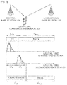
- FIG. 2 illustrates examples of a propagation delay and a delay spread characteristic occurring in a downlink multi-point cooperation of a wireless communication system.
- a neighboring base station 130 may need to adjust a length of a cyclic prefix based on a measured delay spread value.
- the length of the extended cyclic prefix may be determined to satisfy the following Equation 1. L CP i > D P i + D S i
- i denotes a neighboring base station
- L i CP denotes a length of a cyclic prefix needed where a downlink cooperation with the neighboring base station is performed
- D'p denotes a delay difference between a signal received from the neighboring base station and a signal received from a current serving base station
- D i S denotes a delay spread value of the neighboring base station.
- a corresponding neighboring base station 130 may be determined as a cooperation base station 130.
- the corresponding neighboring base station 130 may be determined as the cooperation base station 130.
- R i CoMP denotes a reception capacity of a terminal where the downlink cooperation with the neighboring base station 130 is performed
- R NoCoMP denotes the reception capacity of the terminal where the downlink cooperation is not performed
- L i CP denotes the length of the cyclic prefix needed where the downlink cooperation with the neighboring base station is performed
- L CP denotes a length of a normal cyclic prefix where the downlink cooperation is not performed
- L i data denotes a length of data that may be input where the downlink cooperation with the neighboring base station 130 is performed
- L data denotes a length of data that may be generally input where the downlink cooperation is not performed.
- FIG. 3 illustrates an example of a process of determining an uplink cooperation base station in a wireless communication system.
- an uplink cooperation terminal 320 transmits a reference signal 341 to a serving base station 310 and neighboring base stations 330 and 332, respectively.
- the serving base station 310 measures a channel gain value of the uplink cooperation terminal 320 at operation 342, and measures a delay attribute value of the uplink cooperation terminal 320 at operation 343.
- each of the neighboring base stations 330 and 332 measures the channel gain value of the uplink cooperation terminal 320 at operation 344, and measures the delay attribute value of the uplink cooperation terminal 320 at operation 346. Subsequently, the neighboring base stations 330 and 332 transmit the measured channel gain value and the delay attribute value to the serving base station 310 at operation 347.
- the serving base station 310 determines, as an extended cyclic prefix, a value greater than sum of the propagation delay value and the delay spread value corresponding to each of the neighboring base stations 330 and 332 at operation 348.
- the serving base station 310 determines a neighboring base station to be a cooperation base station, for example, the neighboring base station 330 that includes a multi-point gain compared to an overhead occurring due to an increase in a length of the extended cyclic prefix.
- the neighboring base station 330 is referred to as the cooperation base station 330.
- the serving base station 310 sends a request of an uplink cooperation corresponding to the determined cooperation base station 330.
- the serving base station 310 schedules the uplink cooperation at operation 351, and transmits uplink cooperation scheduling information 352 to the uplink cooperation terminal 320 and the cooperation base station 330, respectively.
- the uplink cooperation terminal 320 transmits uplink cooperation data 353 to the serving base station 310 and the cooperation base station 330, respectively, based on the uplink cooperation scheduling information 352.
- the cooperation base station 330 transfers the uplink cooperation data 354 to the serving base station 310.
- the serving base station 310 In response to the cooperation base station 330 receiving the uplink cooperation data 353 from the uplink cooperation terminal 320 and the serving base station 310 receiving the uplink cooperation data 354 from the cooperation base station 330, the serving base station 310 combines the received uplink cooperation data 353 with the transferred uplink cooperation data 354 at operation 355.
- FIG. 4 illustrates examples of a propagation delay and a delay spread characteristic occurring in an uplink multi-point cooperation of a wireless communication system.
- a delay spread may increase between an uplink cooperation terminal 320 and a non-cooperation terminal 440 within a cooperation base station 330.
- a length of a cyclic prefix may need to increase according to an increased delay spread value.
- the length of the extended cyclic prefix may be determined to satisfy the following Equation 3. L CP i > D P i + D S i
- i denotes a neighboring base station
- L i CP denotes a length of a cyclic prefix needed where an uplink cooperation with the neighboring base station 330 is performed
- D i P denotes a delay difference between a signal of the non-cooperation terminal 440 and a signal of the uplink cooperation terminal 320 received by the neighboring base station 330
- D i S denotes a delay spread value of the uplink cooperation terminal 320.
- a corresponding neighboring base station 330 may be determined as a cooperation base station 330.
- the uplink cooperation with the corresponding neighboring base station 330 may be performed.
- R i CoMP denotes a reception capacity of a serving base station where a multi-node cooperation with the neighboring base station 330 is performed
- R NoCoMP denotes the reception capacity of the serving base station 310 where the multi-node cooperation is not performed
- L i CP denotes the length of the cyclic prefix needed where the uplink cooperation with the neighboring base station 330 is performed
- L CP denotes a length of a normal cyclic prefix where the uplink cooperation is not performed
- L i data denotes a length of data that may be input where the uplink cooperation with the neighboring base station 330 is performed
- L data denotes a length of data that may be generally input where the uplink cooperation is not performed.
- FIG. 5 illustrates an example of an uplink communication process through a multi-point cooperation in a wireless communication system.
- FIG. 5 illustrates effective uplink cooperation scheduling of a serving base station 510.
- uplink cooperation terminals 520 and 522 transmit uplink cooperation data 551 to the serving base station 510 and a cooperation base station 530, respectively.
- the cooperation base station 530 receives uplink non-cooperation data 552 from non-cooperation terminals 540 and 542, respectively, and receives the uplink cooperation data 551 from the uplink cooperation terminals 520 and 522, respectively.
- the cooperation base station 530 transmits the uplink cooperation data to the serving base station 510.
- the cooperation base station 530 measures a delay attribute of each of the uplink cooperation terminals 520 and 522, respectively.
- the delay attribute value may include a propagation delay value and a delay spread value.
- the cooperation base station 530 transmits the measured delay attribute of each of the uplink cooperation terminals 520 and 522 to the serving base station 510.
- the serving base station 510 In response to the serving base station 510 receiving the delay attribute of each of the uplink cooperation terminals 520 and 522 from the cooperation base station 530, the serving base station 510 schedules an uplink cooperation so that uplink cooperation terminals having a similar delay attribute may be located in the same uplink cooperation zone at operation 556.
- the serving base station 510 transmits scheduling information 557 to the uplink cooperation terminals 520 and 522, respectively, and the cooperation base station 530.
- the serving base station 510 transmits framework information 559 of the uplink cooperation zone to the uplink cooperation terminals 520 and 522, respectively.
- the uplink cooperation terminals 520 and 522 In response to the uplink cooperation terminals 520 and 522 receiving the framework information 559, the uplink cooperation terminals 520 and 522 apply a frame format at operation 560.
- the uplink cooperation terminals 520 and 522 transmit uplink cooperation data 562 with the frame format applied based on the framework information to the serving base station 510 and the cooperation base station 530, respectively.
- the cooperation base station 530 transmits framework information of a non-cooperation zone 558 to the non-cooperation terminals 540 and 542.
- the non-cooperation terminals 540 and 542 apply a frame format based on the framework information of the non-cooperation zone 558.
- the non-cooperation terminals 540 and 542 transmits the uplink non-cooperation data 552 with the frame format applied based on the framework information of the non-cooperation zone 558 to the cooperation base station 530.
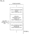
- FIG. 6 illustrates an example of a frame format corresponding to an uplink multi-point cooperation.
- a guard interval 630 is inserted between an uplink cooperation zone 610 and a non-cooperation zone 620 to prevent inter-symbol interference or inter-channel interference.
- a normal cyclic prefix may be used corresponding to the uplink cooperation zone 610 and the non-cooperation zone 620.
- the uplink cooperation zone 610 indicates an uplink zone to provide an uplink cooperation communication corresponding to uplink cooperation terminals having a similar delay attribute.
- the non-cooperation zone 620 indicates an uplink zone to provide the uplink cooperation communication corresponding to non-cooperation terminals.
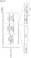
- FIG. 7 illustrates another example of a frame format corresponding to an uplink multi-point cooperation.
- a non-cooperation zone 720 located next to an uplink cooperation zone 710 includes six symbols in six slots, which is one symbol and slot less than the other non-cooperation zone and uplink cooperation zone 710.
- Each of the six symbols may include an extended cyclic prefix 722.
- FIG. 8 illustrates still another example of a frame format corresponding to an uplink multi-point cooperation.
- a length of data 812 included in a last symbol of an uplink cooperation zone 810 may be shortened to prevent interference in a non-cooperation zone 820 that is located next to the uplink cooperation zone 810.
- FIG. 9 illustrates yet another example of a frame format corresponding to an uplink multi-point cooperation.
- a first symbol of a non-cooperation zone 920 located next to an uplink cooperation zone 910 includes an extended cyclic prefix 922 and data 924 having a length shortened by an amount corresponding to an extension of the cyclic prefix 922.
- the guard interval (GI) 926 is inserted into a first symbol of the non-cooperation zone 920 and the first symbol may include data 924 having a length shortened by a length of the guard interval 926.
- a method corresponding to a multi-node cooperation considering a delay in a wireless communication system may perform scheduling so that uplink cooperation terminals having a similar delay attribute may be classified into an uplink cooperation zone, and may provide a frame format to prevent ICI, thereby decreasing overhead occurring due to an increase in a length of a cyclic prefix.
- a trade-off between a performance gain increase according to a multi-node cooperation and an overhead increase according to the increase in the CP length may be solved.
- the processes, functions, methods and/or software described above may be recorded, stored, or fixed in one or more computer-readable storage media that includes program instructions to be implemented by a computer to cause a processor to execute or perform the program instructions.
- the media may also include, alone or in combination with the program instructions, data files, data structures, and the like.
- the media and program instructions may be those specially designed and constructed, or they may be of the kind well-known and available to those having skill in the computer software arts.
- Examples of computer-readable media include magnetic media, such as hard disks, floppy disks, and magnetic tape; optical media such as CD ROM disks and DVDs; magneto-optical media, such as optical disks; and hardware devices that are specially configured to store and perform program instructions, such as read-only memory (ROM), random access memory (RAM), flash memory, and the like.
- Examples of program instructions include machine code, such as produced by a compiler, and files containing higher level code that may be executed by the computer using an interpreter.
- the described hardware devices may be configured to act as one or more software modules in order to perform the operations and methods described above, or vice versa.
- a computer-readable storage medium may be distributed among computer systems connected through a network and computer-readable codes or program instructions may be stored and executed in a decentralized manner.
- a terminal or terminal device described herein may refer to mobile devices such as a cellular phone, a personal digital assistant (PDA), a digital camera, a portable game console, and an MP3 player, a portable/personal multimedia player (PMP), a handheld e-book, a portable lab-top PC, a global positioning system (GPS) navigation, and devices such as a desktop PC, a high definition television (HDTV), an optical disc player, a setup box, and the like capable of wireless communication or communication consistent with that disclosed herein.
- mobile devices such as a cellular phone, a personal digital assistant (PDA), a digital camera, a portable game console, and an MP3 player, a portable/personal multimedia player (PMP), a handheld e-book, a portable lab-top PC, a global positioning system (GPS) navigation, and devices such as a desktop PC, a high definition television (HDTV), an optical disc player, a setup box, and the like capable of wireless communication or communication consistent with that disclosed herein.
- a computing system or a computer may include a microprocessor that is electrically connected with a bus, a user interface, and a memory controller. It may further include a flash memory device.
- the flash memory device may store N-bit data via the memory controller. The N-bit data is processed or will be processed by the microprocessor and N may be 1 or an integer greater than 1.
- a battery may be additionally provided to supply operation voltage of the computing system or computer.
- the computing system or computer may further include an application chipset, a camera image processor (CIS), a mobile Dynamic Random Access Memory (DRAM), and the like.
- the memory controller and the flash memory device may constitute a solid state drive/disk (SSD) that uses a non-volatile memory to store data.
- SSD solid state drive/disk
Landscapes
- Engineering & Computer Science (AREA)
- Signal Processing (AREA)
- Computer Networks & Wireless Communication (AREA)
- Quality & Reliability (AREA)
- Physics & Mathematics (AREA)
- Electromagnetism (AREA)
- Mobile Radio Communication Systems (AREA)
Abstract
Description
- The following description relates to a method of performing a multi-point cooperation in a wireless communication system, and more particularly, to a method of performing a multi-point cooperation that may cluster base stations to participate in a multi-point cooperation based on a delay occurring due to the multi-point cooperation.
- Multi-point cooperation technology enables a plurality of base stations or transmission nodes to cooperate with a terminal located at a cell boundary or a terminal having a weak reception signal, and to simultaneously transmit signals to a corresponding or neighboring terminal to thereby enhance a data rate at the terminal. In response to the terminal located at the cell boundary performing the multi-point cooperation, a propagation delay characteristic of a signal transmitted from a cooperation base station may vary depending on a distance between the cooperation base station and a terminal, and a communication environment. Accordingly, where a plurality of base stations simultaneously transmits signals to a corresponding terminal, the signals may be received by the terminal at various different points in time. A phenomenon that a delay time of each signal varies due to multiple paths may be referred to as a delay spread.
- In a conventional wireless mobile communication system, each symbol may include a guard interval based on the delay spread. The guard interval functions to prevent inter-symbol interference. Generally, to prevent inter-channel interference, a guard interval zone may copy a portion of an end of a transmission symbol and transmit the copied portion, which is referred to as a cyclic prefix (CP). A cyclic prefix length may be determined based on a delay spread value. The inter-symbol interference or the inter-channel interference may not occur where the cyclic prefix length is greater than the delay spread value.
- In the case of the multi-point cooperation, a multi-point cooperation gain may increase according to an increase in a number of base stations participating in the multi-point cooperation. However, in this case, the delay spread may also increase and the cyclic prefix length may also require an increase. As a result, the increase in the cyclic prefix length may cause an overhead, wasting radio resources.
- Accordingly, in the case of the multi-point cooperation, a trade-off relationship may exist between a performance gain increasing according to an increasing in the number of cooperation base stations and the overhead occurring due to the increase in the cyclic prefix length.
- In one general aspect, a method to perform a downlink multi-point cooperation at a serving base station of a wireless communication system, includes transmitting a reference signal, receiving, from a downlink cooperation terminal, a channel gain value, a propagation delay value, and a delay spread value that are calculated by the downlink cooperation terminal with respect to each of the serving base station and a plurality of neighboring base stations, determining a length of an extended cyclic prefix of each of the plurality of neighboring base stations based on the propagation delay value and the delay spread value, and determining, as a cooperation base station, one of the plurality of the neighboring base stations that includes a multi-point cooperation gain compared to an overhead occurring due to an increase in the length of the extended cyclic prefix.
- The determining of the length of the extended cyclic prefix may include determining, as the extended cyclic prefix, a value greater than a sum of the propagation delay value and the delay spread value corresponding to each of the neighboring base stations.
- The method may further include requesting the determined cooperation base station corresponding to a downlink cooperation, scheduling a downlink cooperation, transmitting downlink cooperation scheduling information to the downlink cooperation terminal and the cooperation base station, and transmitting downlink cooperation data to the downlink cooperation terminal and the cooperation base station based on the downlink cooperation scheduling information.
- In response to the downlink cooperation terminal receiving downlink cooperation data from the serving base station, and receiving downlink cooperation data from the cooperation base station, the downlink cooperation terminal may combine the downlink cooperation data of the serving base station with the downlink cooperation data of the cooperation base station.
- In another general aspect, a method of performing an uplink multi-point cooperation at a serving base station of a wireless communication system, includes receiving a reference signal from a terminal, calculating a channel gain value, a propagation delay value, and a delay spread value of the serving base station based on the reference signal, receiving, from a plurality of neighboring base stations, a channel gain value, a propagation delay value, and a delay spread value of each of the plurality of neighboring base stations that are calculated based on the reference signal, determining a length of an extended cyclic prefix of each of the plurality of neighboring base stations based on the propagation delay value and the delay spread value, and determining, as a cooperation base station, a neighboring base station from among the plurality of neighboring base stations that includes a multi-point cooperation gain compared to an overhead occurring due to an increase in the length of the extended cyclic prefix.
- The determining of the length of the extended cyclic prefix may include determining, as the extended cyclic prefix, a value greater than an addition value of the propagation delay value and the delay spread value corresponding to each of the neighboring base stations.
- The method may further include requesting the determined cooperation base station corresponding to an uplink cooperation, scheduling an uplink cooperation, transmitting uplink cooperation scheduling information to the terminal and the cooperation base station, and transmitting the uplink cooperation data to the terminal and the cooperation base station based on the uplink cooperation scheduling information.
- In response to the terminal receiving uplink cooperation data from the serving base station and receiving uplink cooperation data from the cooperation base station, the terminal may combine the uplink cooperation data of the serving base station with the uplink cooperation data of the cooperation base station.
- In still another general aspect, a method of performing an uplink multi-point cooperation at a serving base station of a wireless communication system, includes receiving uplink cooperation data from uplink cooperation terminals, receiving, from a cooperation base station, uplink cooperation data of each of the uplink cooperative terminals received at the cooperation base station, receiving, from the cooperation base station, a delay attribute of each of the uplink cooperation terminals calculated at the cooperation base station, and scheduling the uplink cooperation terminals so that the uplink cooperation terminals having a similar delay attribute are located in the same uplink cooperation zone.
- The scheduling may include dividing an uplink into an uplink cooperation zone and a non-cooperation zone, and scheduling the uplink cooperation terminals so that the uplink cooperation terminals having the similar delay attribute are located in the same uplink cooperation zone.
- The scheduling may include inserting a guard interval between the uplink cooperation zone and the non-cooperation zone.
- The method may further include transmitting scheduling information to the uplink cooperation terminals and the cooperation base station, and transmitting framework information of the uplink cooperation zone to the uplink cooperation terminals.
- The framework information of the uplink cooperation zone may include information regarding a frame format of the uplink cooperation zone, a length of a guard interval, a length of a cyclic prefix, and a length of data.
- In the framework information of the uplink cooperation zone, a length of data included in a last symbol of the uplink cooperation zone may be shortened to prevent interference in the non-cooperation zone that is located next to the uplink cooperation zone.
- In response to the cooperation base station receiving the scheduling information, the cooperation base station may transmit framework information of a non-cooperation zone to uplink non-cooperation terminals included in the cooperation base station.
- In response to the framework information of the non-cooperation zone being located next to the uplink cooperation zone, the framework information of the non-cooperation zone may include six symbols and each of the six symbols may include an extended cyclic prefix.
- In response to the framework information of the non-cooperation zone being located next to the uplink cooperation zone, a first symbol of the non-cooperation zone may include an extended cyclic prefix and data having a length shortened by an amount corresponding to an extension of the extended cyclic prefix.
- In response to the framework information of the non-cooperation zone being located next the uplink cooperation zone, a guard interval may be inserted into a first symbol of the non-cooperation zone and the first symbol may include data having a length shortened by a length of the guard interval.
- In still another aspect, there is provided a method to perform a downlink and/or uplink multi-point cooperation at a serving base station according to any one of the following clauses:
- 1) A method to perform a downlink multi-point cooperation at a serving base station of a wireless communication system, the method comprising:
- transmitting a reference signal;
- receiving, from a downlink cooperation terminal, a channel gain value, a propagation delay value, and a delay spread value that are calculated by the downlink cooperation terminal with respect to each of the serving base station and a plurality of neighboring base stations;
- determining a length of an extended cyclic prefix of each of the plurality of neighboring base stations based on the propagation delay value and the delay spread value; and
- determining, as a cooperation base station, one of the plurality of the neighboring base stations to include a multi-point cooperation gain compared to an overhead occurring due to an increase in the length of the extended cyclic prefix.
- 2) The method of clause 1), wherein the determining of the length of the extended cyclic prefix comprises determining, as the extended cyclic prefix, a value greater than a sum of the propagation delay value and the delay spread value corresponding to each of the neighboring base stations.
- 3) The method of clause 1) or 2), further comprising:
- requesting the determined cooperation base station corresponding to a downlink cooperation;
- scheduling a downlink cooperation;
- transmitting downlink cooperation scheduling information to the downlink cooperation terminal and the cooperation base station; and
- transmitting downlink cooperation data to the downlink cooperation terminal and the cooperation base station based on the downlink cooperation scheduling information.
- 4) The method of clause 3), wherein, in response to the downlink cooperation terminal receiving downlink cooperation data from the serving base station and receiving downlink cooperation data from the cooperation base station, the downlink cooperation terminal combines the downlink cooperation data of the serving base station with the downlink cooperation data of the cooperation base station.
- 5) A method of performing an uplink multi-point cooperation at a serving base station of a wireless communication system, the method comprising:
- receiving a reference signal from a terminal;
- calculating a channel gain value, a propagation delay value, and a delay spread value of the serving base station based on the reference signal;
- receiving, from a plurality of neighboring base stations, a channel gain value, a propagation delay value, and a delay spread value of each of the plurality of neighboring base stations that are calculated based on the reference signal;
- determining a length of an extended cyclic prefix of each of the plurality of neighboring base stations based on the propagation delay value and the delay spread value; and
- determining, as a cooperation base station, a neighboring base station from among the plurality of neighboring base stations that includes a multi-point cooperation gain compared to an overhead occurring due to an increase in the length of the extended cyclic prefix.
- 6) The method of clause 5), wherein the determining of the length of the extended cyclic prefix comprises determining, as the extended cyclic prefix, a value greater than an addition value of the propagation delay value and the delay spread value corresponding to each of the neighboring base stations.
- 7) The method of clause 5) or 6), further comprising:
- requesting the determined cooperation base station corresponding to an uplink cooperation;
- scheduling an uplink cooperation;
- transmitting uplink cooperation scheduling information to the terminal and the cooperation base station; and
- receiving uplink cooperation data based on the uplink cooperation scheduling information.
- 8) The method of clause 7), wherein, in response to the serving base station receiving uplink cooperation data from terminal and receiving uplink cooperation data from the cooperation base station, the serving base station combines the uplink cooperation data of the terminal with the uplink cooperation data of the cooperation base station.
- Other features and aspects will be apparent from the following detailed description, the drawings, and the claims.
-
-
FIG. 1 is a diagram illustrating an example of a process of determining a downlink cooperation base station in a wireless communication system. -
FIG. 2 is a diagram illustrating examples of a propagation delay and a delay spread characteristic occurring in a downlink multi-point cooperation of a wireless communication system. -
FIG. 3 is a diagram illustrating an example of a process of determining an uplink cooperation base station in a wireless communication system. -
FIG. 4 is a diagram illustrating examples of a propagation delay and a delay spread characteristic occurring in an uplink multi-point cooperation of a wireless communication system. -
FIG. 5 is a diagram illustrating an example of an uplink communication process through a multi-point cooperation in a wireless communication system. -
FIG. 6 is a diagram illustrating an example of a frame format corresponding to an uplink multi-point cooperation. -
FIG. 7 is a diagram illustrating another example of a frame format corresponding to an uplink multi-point cooperation. -
FIG. 8 is a diagram illustrating still another example of a frame format corresponding to an uplink multi-point cooperation. -
FIG. 9 is a diagram illustrating yet another example of a frame format corresponding to an uplink multi-point cooperation. - Throughout the drawings and the detailed description, unless otherwise described, the same drawing reference numerals will be understood to refer to the same elements, features, and structures. The relative size and depiction of these elements may be exaggerated for clarity, illustration, and convenience.
- The following detailed description is provided to assist the reader in gaining a comprehensive understanding of the methods, apparatuses, and/or systems described herein. Accordingly, various changes, modifications, and equivalents of the systems, apparatuses, and/or methods described herein will be suggested to those of ordinary skill in the art. The progression of processing steps and/or operations described is an example; however, the sequence of and/or operations is not limited to that set forth herein and may be changed as is known in the art, with the exception of steps and/or operations necessarily occurring in a certain order. Also, description of well-known functions and constructions may be omitted for increased clarity and conciseness.
-
FIG. 1 illustrates an example of a process of determining a downlink cooperation base station in a wireless communication system. - Referring to
FIG. 1 , adownlink cooperation terminal 120 receives areference signal 141 from a servingbase station 110, and also receives reference signals 142 and 143 from neighboringbase stations downlink cooperation terminal 120 measures a channel gain value Hi of each of the servingbase station 110 and the neighboringbase stations reference signals downlink cooperation terminal 120 measures a delay attribute value of each of the servingbase station 110 and the neighboringbase stations reference signals - At 149, the
downlink cooperation terminal 120 transmits both the measured channel gain value and the delay attribute value to the servingbase station 110. - In response to the serving
base station 110 receiving the channel gain value and the delay attribute value from thedownlink cooperation terminal 120, , the servingbase station 110 determines, as an extended cyclic prefix (CP), a value greater than sum of the propagation delay value and the delay spread value corresponding to each of the neighboringbase stations - At 152, the serving
base station 110 determines a neighboring base station to be a cooperation base station, for example, the neighboringbase station 130 that includes a multi-point gain compared to an overhead occurring due to an increase in the length of the extended cyclic prefix. Hereinafter, the neighboringbase station 130 is referred to as thecooperation base station 130. - At 153, the serving
base station 110 sends a request of a downlink cooperation corresponding to the determinedcooperation base station 130. In response to thecooperation base station 130 accepting the downlink cooperation request, the servingbase station 110 schedules the downlink cooperation at 154, and subsequently transmits downlinkcooperation scheduling information 155 to thedownlink cooperation terminal 120 and thecooperation base station 130, respectively. - The serving
base station 110 also transmitsdownlink cooperation data 156 to thedownlink cooperation terminal 120 and thecooperation base station 130, respectively, based on the downlinkcooperation scheduling information 155. - The
cooperation base station 130 transfers thedownlink cooperation data 157 to thedownlink cooperation terminal 120. - In response to the
downlink cooperation terminal 120 receiving thedownlink cooperation data 156 from the servingbase station 110 and thedownlink cooperation data 157 from thecooperation base station 130, thedownlink cooperation terminal 120 combines thedownlink cooperation data 156 of the servingbase station 110 with thedownlink cooperation data 157 of thecooperation base station 130 at 158. - Referring to
FIG. 1 , a scheme of determining the length of the extended cyclic prefix at 150 and a scheme of determining the cooperation base station at 152 will be further described with reference toFIG. 2 . -
FIG. 2 illustrates examples of a propagation delay and a delay spread characteristic occurring in a downlink multi-point cooperation of a wireless communication system. - Referring to
FIG. 2 , to provide the multi-point cooperation, a neighboringbase station 130 may need to adjust a length of a cyclic prefix based on a measured delay spread value. The length of the extended cyclic prefix may be determined to satisfy the following Equation 1.
- In the above example depicted in Equation 1, i denotes a neighboring base station, Li CP denotes a length of a cyclic prefix needed where a downlink cooperation with the neighboring base station is performed, D'p denotes a delay difference between a signal received from the neighboring base station and a signal received from a current serving base station, and Di S denotes a delay spread value of the neighboring base station.
- Referring to
FIG. 2 , in response to a multi-point cooperation gain existing as compared to an overhead occurring due to an increase in the length of the extended cyclic prefix according to the above Equation 1 existing, a corresponding neighboringbase station 130 may be determined as acooperation base station 130. For example, where the following Equation 2 is satisfied, the corresponding neighboringbase station 130 may be determined as thecooperation base station 130.
- In the above example depicted in Equation 2, Ri CoMP denotes a reception capacity of a terminal where the downlink cooperation with the neighboring
base station 130 is performed, RNoCoMP denotes the reception capacity of the terminal where the downlink cooperation is not performed, Li CP denotes the length of the cyclic prefix needed where the downlink cooperation with the neighboring base station is performed, LCP denotes a length of a normal cyclic prefix where the downlink cooperation is not performed, Li data denotes a length of data that may be input where the downlink cooperation with the neighboringbase station 130 is performed, and Ldata denotes a length of data that may be generally input where the downlink cooperation is not performed. -
FIG. 3 illustrates an example of a process of determining an uplink cooperation base station in a wireless communication system. - Referring to
FIG. 3 , an uplink cooperation terminal 320 transmits areference signal 341 to a servingbase station 310 and neighboringbase stations - Where the
reference signal 341 is received, the servingbase station 310 measures a channel gain value of the uplink cooperation terminal 320 atoperation 342, and measures a delay attribute value of the uplink cooperation terminal 320 atoperation 343. - In response to the
reference signal 341 being received, each of the neighboringbase stations operation 344, and measures the delay attribute value of the uplink cooperation terminal 320 atoperation 346. Subsequently, the neighboringbase stations base station 310 atoperation 347. - In response to the serving
base station 310 receiving the channel gain value and the delay attribute value from each of the neighboringbase stations base station 310 determines, as an extended cyclic prefix, a value greater than sum of the propagation delay value and the delay spread value corresponding to each of the neighboringbase stations operation 348. Atoperation 349, the servingbase station 310 determines a neighboring base station to be a cooperation base station, for example, the neighboringbase station 330 that includes a multi-point gain compared to an overhead occurring due to an increase in a length of the extended cyclic prefix. Hereinafter, the neighboringbase station 330 is referred to as thecooperation base station 330. - At
operation 350, the servingbase station 310 sends a request of an uplink cooperation corresponding to the determinedcooperation base station 330. In response to thecooperation base station 330 accepting the uplink cooperation request, the servingbase station 310 schedules the uplink cooperation atoperation 351, and transmits uplinkcooperation scheduling information 352 to the uplink cooperation terminal 320 and thecooperation base station 330, respectively. - In response to the uplink cooperation scheduling information being received, the uplink cooperation terminal 320 transmits
uplink cooperation data 353 to the servingbase station 310 and thecooperation base station 330, respectively, based on the uplinkcooperation scheduling information 352. - Subsequently, the
cooperation base station 330 transfers theuplink cooperation data 354 to the servingbase station 310. - In response to the
cooperation base station 330 receiving theuplink cooperation data 353 from the uplink cooperation terminal 320 and the servingbase station 310 receiving theuplink cooperation data 354 from thecooperation base station 330, the servingbase station 310 combines the receiveduplink cooperation data 353 with the transferreduplink cooperation data 354 atoperation 355. -
FIG. 4 illustrates examples of a propagation delay and a delay spread characteristic occurring in an uplink multi-point cooperation of a wireless communication system. - Unlike a downlink cooperation, in the case of an uplink cooperation, a delay spread may increase between an uplink cooperation terminal 320 and a
non-cooperation terminal 440 within acooperation base station 330. A length of a cyclic prefix may need to increase according to an increased delay spread value. The length of the extended cyclic prefix may be determined to satisfy the following Equation 3.
- In the above example according to Equation 3, i denotes a neighboring base station, Li CP denotes a length of a cyclic prefix needed where an uplink cooperation with the neighboring
base station 330 is performed, Di P denotes a delay difference between a signal of thenon-cooperation terminal 440 and a signal of the uplink cooperation terminal 320 received by the neighboringbase station 330, and Di S denotes a delay spread value of the uplink cooperation terminal 320. - Referring to
FIG. 4 , in response to an uplink cooperation gain existing as compared to an overhead occurring due to an increase in the length of the extended cyclic prefix according to the above Equation 3 existing, a corresponding neighboringbase station 330 may be determined as acooperation base station 330. For example, where the following Equation 4 is satisfied, the uplink cooperation with the corresponding neighboringbase station 330 may be performed.
- In the above example depicted in Equation 4, Ri CoMP denotes a reception capacity of a serving base station where a multi-node cooperation with the neighboring
base station 330 is performed, RNoCoMP denotes the reception capacity of the servingbase station 310 where the multi-node cooperation is not performed, Li CP denotes the length of the cyclic prefix needed where the uplink cooperation with the neighboringbase station 330 is performed, LCP denotes a length of a normal cyclic prefix where the uplink cooperation is not performed, Li data denotes a length of data that may be input where the uplink cooperation with the neighboringbase station 330 is performed, and Ldata denotes a length of data that may be generally input where the uplink cooperation is not performed. -
FIG. 5 illustrates an example of an uplink communication process through a multi-point cooperation in a wireless communication system.FIG. 5 illustrates effective uplink cooperation scheduling of a servingbase station 510. - Referring to
FIG. 5 ,uplink cooperation terminals uplink cooperation data 551 to the servingbase station 510 and acooperation base station 530, respectively. - Referring to
FIG. 5 , thecooperation base station 530 receivesuplink non-cooperation data 552 fromnon-cooperation terminals uplink cooperation data 551 from theuplink cooperation terminals operation 553, thecooperation base station 530 transmits the uplink cooperation data to the servingbase station 510. Atoperation 554, thecooperation base station 530 measures a delay attribute of each of theuplink cooperation terminals operation 555, thecooperation base station 530 transmits the measured delay attribute of each of theuplink cooperation terminals base station 510. - In response to the serving
base station 510 receiving the delay attribute of each of theuplink cooperation terminals cooperation base station 530, the servingbase station 510 schedules an uplink cooperation so that uplink cooperation terminals having a similar delay attribute may be located in the same uplink cooperation zone atoperation 556. - The serving
base station 510 transmitsscheduling information 557 to theuplink cooperation terminals cooperation base station 530. The servingbase station 510 transmitsframework information 559 of the uplink cooperation zone to theuplink cooperation terminals - In response to the
uplink cooperation terminals framework information 559, theuplink cooperation terminals operation 560. Theuplink cooperation terminals uplink cooperation data 562 with the frame format applied based on the framework information to the servingbase station 510 and thecooperation base station 530, respectively. - The
cooperation base station 530 transmits framework information of anon-cooperation zone 558 to thenon-cooperation terminals - At
operation 561, thenon-cooperation terminals non-cooperation zone 558. Atoperation 563, thenon-cooperation terminals uplink non-cooperation data 552 with the frame format applied based on the framework information of thenon-cooperation zone 558 to thecooperation base station 530. - Hereinafter, types of frame formats according to the framework information of a non-cooperation zone and the framework information of an uplink cooperation zone to prevent inter-symbol interference or inter-channel interference will be described with reference to
FIGS. 6 through 9 . -
FIG. 6 illustrates an example of a frame format corresponding to an uplink multi-point cooperation. Referring toFIG. 6 , aguard interval 630 is inserted between anuplink cooperation zone 610 and anon-cooperation zone 620 to prevent inter-symbol interference or inter-channel interference. Instead of an extended cyclic prefix, a normal cyclic prefix may be used corresponding to theuplink cooperation zone 610 and thenon-cooperation zone 620. - The
uplink cooperation zone 610 indicates an uplink zone to provide an uplink cooperation communication corresponding to uplink cooperation terminals having a similar delay attribute. Thenon-cooperation zone 620 indicates an uplink zone to provide the uplink cooperation communication corresponding to non-cooperation terminals. -
FIG. 7 illustrates another example of a frame format corresponding to an uplink multi-point cooperation. Referring toFIG. 7 , in the frame format, anon-cooperation zone 720 located next to an uplink cooperation zone 710 includes six symbols in six slots, which is one symbol and slot less than the other non-cooperation zone and uplink cooperation zone 710. Each of the six symbols may include an extendedcyclic prefix 722. -
FIG. 8 illustrates still another example of a frame format corresponding to an uplink multi-point cooperation. Referring toFIG. 8 , a length ofdata 812 included in a last symbol of an uplink cooperation zone 810 may be shortened to prevent interference in a non-cooperation zone 820 that is located next to the uplink cooperation zone 810. -
FIG. 9 illustrates yet another example of a frame format corresponding to an uplink multi-point cooperation. Referring toFIG. 9 , a first symbol of a non-cooperation zone 920 located next to an uplink cooperation zone 910 includes an extendedcyclic prefix 922 anddata 924 having a length shortened by an amount corresponding to an extension of thecyclic prefix 922. Also, the guard interval (GI) 926 is inserted into a first symbol of the non-cooperation zone 920 and the first symbol may includedata 924 having a length shortened by a length of theguard interval 926. - According to above example embodiments, where an uplink cooperation is performed, a method corresponding to a multi-node cooperation considering a delay in a wireless communication system may perform scheduling so that uplink cooperation terminals having a similar delay attribute may be classified into an uplink cooperation zone, and may provide a frame format to prevent ICI, thereby decreasing overhead occurring due to an increase in a length of a cyclic prefix. A trade-off between a performance gain increase according to a multi-node cooperation and an overhead increase according to the increase in the CP length may be solved.
- The processes, functions, methods and/or software described above may be recorded, stored, or fixed in one or more computer-readable storage media that includes program instructions to be implemented by a computer to cause a processor to execute or perform the program instructions. The media may also include, alone or in combination with the program instructions, data files, data structures, and the like. The media and program instructions may be those specially designed and constructed, or they may be of the kind well-known and available to those having skill in the computer software arts. Examples of computer-readable media include magnetic media, such as hard disks, floppy disks, and magnetic tape; optical media such as CD ROM disks and DVDs; magneto-optical media, such as optical disks; and hardware devices that are specially configured to store and perform program instructions, such as read-only memory (ROM), random access memory (RAM), flash memory, and the like. Examples of program instructions include machine code, such as produced by a compiler, and files containing higher level code that may be executed by the computer using an interpreter. The described hardware devices may be configured to act as one or more software modules in order to perform the operations and methods described above, or vice versa. In addition, a computer-readable storage medium may be distributed among computer systems connected through a network and computer-readable codes or program instructions may be stored and executed in a decentralized manner.
- As a non-exhaustive illustration only, a terminal or terminal device described herein may refer to mobile devices such as a cellular phone, a personal digital assistant (PDA), a digital camera, a portable game console, and an MP3 player, a portable/personal multimedia player (PMP), a handheld e-book, a portable lab-top PC, a global positioning system (GPS) navigation, and devices such as a desktop PC, a high definition television (HDTV), an optical disc player, a setup box, and the like capable of wireless communication or communication consistent with that disclosed herein.
- A computing system or a computer may include a microprocessor that is electrically connected with a bus, a user interface, and a memory controller. It may further include a flash memory device. The flash memory device may store N-bit data via the memory controller. The N-bit data is processed or will be processed by the microprocessor and N may be 1 or an integer greater than 1. Where the computing system or computer is a mobile apparatus, a battery may be additionally provided to supply operation voltage of the computing system or computer. It will be apparent to those of ordinary skill in the art that the computing system or computer may further include an application chipset, a camera image processor (CIS), a mobile Dynamic Random Access Memory (DRAM), and the like. The memory controller and the flash memory device may constitute a solid state drive/disk (SSD) that uses a non-volatile memory to store data.
- A number of examples have been described above. Nevertheless, it will be understood that various modifications may be made. For example, suitable results may be achieved if the described techniques are performed in a different order and/or if components in a described system, architecture, device, or circuit are combined in a different manner and/or replaced or supplemented by other components or their equivalents. Accordingly, other implementations are within the scope of the following claims.
Claims (7)
- A method of performing an uplink multi-point cooperation at a serving base station (510) of a wireless communication system, the method comprising:receiving uplink cooperation data from uplink cooperation terminals (551);receiving, from a cooperation base station, uplink cooperation data of each of the uplink cooperative terminals received at the cooperation base station (553);receiving, from the cooperation base station, a delay attribute of each of the uplink cooperation terminals calculated at the cooperation base station (555); andscheduling the uplink cooperation terminals so that the uplink cooperation terminals having a similar delay attribute are located in the same uplink cooperation zone (556).
- The method of claim 1, wherein the scheduling comprises:dividing an uplink into an uplink cooperation zone and a non-cooperation zone; andscheduling the uplink cooperation terminals so that the uplink cooperation terminals having the similar delay attribute are located in the same uplink cooperation zone.
- The method of claim 2, wherein the scheduling comprises inserting a guard interval between the uplink cooperation zone and the non-cooperation zone.
- The method of any of the preceding claims, further comprising:transmitting scheduling information to the uplink cooperation terminals and the cooperation base station (557); andtransmitting framework information of the uplink cooperation zone to the uplink cooperation terminals (559).
- The method of claim 4, wherein the framework information of the uplink cooperation zone includes information regarding a frame format of the uplink cooperation zone, a length of a guard interval, a length of a cyclic prefix, and a length of data.
- The method of claim 4 or 5, wherein, in the framework information of the uplink cooperation zone, a length of data included in a last symbol of the uplink cooperation zone is shortened to prevent interference in the non-cooperation zone that is located next to the uplink cooperation zone.
- The method of any of the claims 4-6, wherein, in response to the cooperation base station receiving the scheduling information, the cooperation base station transmits framework information of a non-cooperation zone to uplink non-cooperation terminals included in the cooperation base station (558).
Applications Claiming Priority (3)
| Application Number | Priority Date | Filing Date | Title |
|---|---|---|---|
| KR1020090089354A KR101633495B1 (en) | 2009-09-22 | 2009-09-22 | Method for multi-point cooperation that consider delay in wireless communication system |
| PCT/KR2010/006200 WO2011037345A2 (en) | 2009-09-22 | 2010-09-13 | Method for multi-point cooperation considering delay in wireless communication system |
| EP10818986.1A EP2481173B1 (en) | 2009-09-22 | 2010-09-13 | Method for multi-point cooperation considering delay in wireless communication system |
Related Parent Applications (1)
| Application Number | Title | Priority Date | Filing Date |
|---|---|---|---|
| EP10818986.1A Division EP2481173B1 (en) | 2009-09-22 | 2010-09-13 | Method for multi-point cooperation considering delay in wireless communication system |
Publications (2)
| Publication Number | Publication Date |
|---|---|
| EP3306832A1 true EP3306832A1 (en) | 2018-04-11 |
| EP3306832B1 EP3306832B1 (en) | 2021-05-12 |
Family
ID=43757061
Family Applications (2)
| Application Number | Title | Priority Date | Filing Date |
|---|---|---|---|
| EP10818986.1A Active EP2481173B1 (en) | 2009-09-22 | 2010-09-13 | Method for multi-point cooperation considering delay in wireless communication system |
| EP17203768.1A Active EP3306832B1 (en) | 2009-09-22 | 2010-09-13 | Method for multi-point cooperation considering delay in wireless communication system |
Family Applications Before (1)
| Application Number | Title | Priority Date | Filing Date |
|---|---|---|---|
| EP10818986.1A Active EP2481173B1 (en) | 2009-09-22 | 2010-09-13 | Method for multi-point cooperation considering delay in wireless communication system |
Country Status (6)
| Country | Link |
|---|---|
| US (1) | US8812675B2 (en) |
| EP (2) | EP2481173B1 (en) |
| JP (1) | JP5580422B2 (en) |
| KR (1) | KR101633495B1 (en) |
| CN (1) | CN102549941B (en) |
| WO (1) | WO2011037345A2 (en) |
Families Citing this family (17)
| Publication number | Priority date | Publication date | Assignee | Title |
|---|---|---|---|---|
| US8731001B2 (en) | 2011-05-31 | 2014-05-20 | Broadcom Corporation | Methods and apparatus for determining participants in coordinated multi-point transmission |
| GB2491367B (en) * | 2011-05-31 | 2013-05-08 | Renesas Mobile Corp | Methods and apparatus for determining participants in coordinated multi-point transmission |
| GB2491426B (en) * | 2011-05-31 | 2013-05-08 | Renesas Mobile Corp | Methods and apparatus for determining participants in coordinated multi-point transmission |
| EP2735204A1 (en) * | 2011-07-21 | 2014-05-28 | BlackBerry Limited | Dynamic cyclic prefix mode for uplink radio resource management |
| CN102291223B (en) * | 2011-08-05 | 2014-03-12 | 电信科学技术研究院 | Channel state information feedback indication and feedback method and device |
| JP5814041B2 (en) * | 2011-08-12 | 2015-11-17 | 株式会社Nttドコモ | Radio communication system, radio base station apparatus, user terminal, and radio communication method |
| KR101839808B1 (en) * | 2011-08-24 | 2018-04-26 | 삼성전자주식회사 | Mobile Terminal and Communication Method, Base Station Control Apparatus and Method, and Multi-Point Transmission System and Method using the Same |
| EP2768268A4 (en) * | 2011-10-13 | 2015-12-02 | Fujitsu Ltd | WIRELESS COMMUNICATION SYSTEM, BASE STATION, AND WIRELESS COMMUNICATION METHOD |
| CN104137637B (en) | 2012-07-20 | 2018-11-09 | 华为技术有限公司 | A service transmission method, device, readable storage medium and system |
| CN103812624A (en) * | 2012-11-07 | 2014-05-21 | 上海贝尔股份有限公司 | Cooperative multi-point transmission method |
| CN103347283B (en) * | 2013-06-18 | 2016-03-09 | 华中科技大学 | A kind of adaptive cooperative multi-point transmission method |
| CN105850214B (en) * | 2014-09-29 | 2019-09-03 | 华为技术有限公司 | Wireless network scheduling method, access device and wireless network |
| US10505685B2 (en) * | 2016-08-26 | 2019-12-10 | Qualcomm Incorporated | Adapting to delay spread variation in wireless communication systems |
| US10595332B2 (en) * | 2016-09-30 | 2020-03-17 | Qualcomm Incorporated | Aligning slots allocated to extended cyclic prefix symbols with slots allocated to normal cyclic prefix symbols |
| US10063306B2 (en) * | 2016-10-24 | 2018-08-28 | Mitsubishi Electric Research Laboratories, Inc. | Method and systems using quasi-synchronous distributed CDD systems |
| CN108616977B (en) * | 2018-06-21 | 2020-06-16 | 同济大学 | UWB (ultra wide band) multipoint time delay correction method based on least square adjustment |
| WO2020088769A1 (en) * | 2018-11-01 | 2020-05-07 | Nokia Solutions And Networks Gmbh & Co. Kg | Method and apparatus for handover |
Family Cites Families (11)
| Publication number | Priority date | Publication date | Assignee | Title |
|---|---|---|---|---|
| KR101293360B1 (en) * | 2006-09-11 | 2013-08-05 | 연세대학교 산학협력단 | Cooperative transmission method for OFDMA mobile communication system and user equipment |
| CA2663976A1 (en) | 2006-10-24 | 2008-05-02 | Qualcomm Incorporated | Enabling resource partitioning for wireless communication systems |
| KR101303652B1 (en) * | 2007-01-05 | 2013-09-04 | 인하대학교 산학협력단 | Method and apparatus for managing a cooperative diversity system |
| US8780771B2 (en) | 2007-02-06 | 2014-07-15 | Qualcomm Incorporated | Cyclic delay diversity and precoding for wireless communication |
| US8331331B2 (en) * | 2007-08-03 | 2012-12-11 | Qualcomm Incorporated | Method and apparatus for determining cell timing in a wireless communication system |
| KR100969147B1 (en) * | 2007-11-29 | 2010-07-08 | 한국전자통신연구원 | Method of cooperative reception diversity, selective cooperative communication method and system |
| KR101048437B1 (en) | 2007-11-30 | 2011-07-11 | 삼성전자주식회사 | Method and apparatus for time varying cyclic delay diversity in wireless communication system |
| US20100189038A1 (en) * | 2009-01-23 | 2010-07-29 | Runhua Chen | Circuit and method for mapping data symbols and reference signals for coordinated multi-point systems |
| US7940740B2 (en) * | 2009-02-03 | 2011-05-10 | Motorola Mobility, Inc. | Apparatus and method for communicating and processing a positioning reference signal based on identifier associated with a base station |
| WO2011023217A1 (en) * | 2009-08-24 | 2011-03-03 | Nokia Siemens Networks Oy | Controlling scheduling decisions in a distributed cooperation system |
| CN102598783B (en) * | 2009-11-02 | 2016-05-04 | 夏普株式会社 | Mobile communication system, mobile station device and reconnection method |
-
2009
- 2009-09-22 KR KR1020090089354A patent/KR101633495B1/en active Active
-
2010
- 2010-03-25 US US12/731,296 patent/US8812675B2/en active Active
- 2010-09-13 JP JP2012530768A patent/JP5580422B2/en active Active
- 2010-09-13 WO PCT/KR2010/006200 patent/WO2011037345A2/en not_active Ceased
- 2010-09-13 EP EP10818986.1A patent/EP2481173B1/en active Active
- 2010-09-13 CN CN201080042238.0A patent/CN102549941B/en active Active
- 2010-09-13 EP EP17203768.1A patent/EP3306832B1/en active Active
Non-Patent Citations (2)
| Title |
|---|
| HUAWEI: "System modeling and performance evaluation for uplink CoMP considering delay spread issue", 3GPP DRAFT; R1-092368, 3RD GENERATION PARTNERSHIP PROJECT (3GPP), MOBILE COMPETENCE CENTRE ; 650, ROUTE DES LUCIOLES ; F-06921 SOPHIA-ANTIPOLIS CEDEX ; FRANCE, no. Los Angeles, USA; 20090624, 24 June 2009 (2009-06-24), XP050350887 * |
| TOKYO INSTITUTE OF TECHNOLOGY ET AL: "Distributed Dynamic CoMP for LTE-Advanced", 3GPP DRAFT; R1-093608 DISTRIBUTED DYNAMIC COMP FOR LTE ADVANCED (REVISED FROM R1-093081), 3RD GENERATION PARTNERSHIP PROJECT (3GPP), MOBILE COMPETENCE CENTRE ; 650, ROUTE DES LUCIOLES ; F-06921 SOPHIA-ANTIPOLIS CEDEX ; FRANCE, no. Shenzhen, China; 20090824, 24 August 2009 (2009-08-24), XP050388177 * |
Also Published As
| Publication number | Publication date |
|---|---|
| CN102549941B (en) | 2014-12-17 |
| EP2481173A2 (en) | 2012-08-01 |
| KR20110032046A (en) | 2011-03-30 |
| KR101633495B1 (en) | 2016-06-24 |
| EP2481173B1 (en) | 2017-12-20 |
| EP2481173A4 (en) | 2015-07-08 |
| US8812675B2 (en) | 2014-08-19 |
| WO2011037345A2 (en) | 2011-03-31 |
| US20110070884A1 (en) | 2011-03-24 |
| WO2011037345A3 (en) | 2011-08-04 |
| JP2013505659A (en) | 2013-02-14 |
| JP5580422B2 (en) | 2014-08-27 |
| CN102549941A (en) | 2012-07-04 |
| EP3306832B1 (en) | 2021-05-12 |
Similar Documents
| Publication | Publication Date | Title |
|---|---|---|
| EP3306832B1 (en) | Method for multi-point cooperation considering delay in wireless communication system | |
| CN115004720B (en) | Retransmission of sidelink positioning reference signals | |
| US8971264B2 (en) | Communication method of terminals and access point for uplink MU-MIMO channel access | |
| EP3713291B1 (en) | Resource allocation indication and receiving methods and devices | |
| CN109802789B (en) | Method and equipment for configuring time-frequency domain resources for transmitting common control information | |
| CN112468278A (en) | Method and device for determining resources | |
| US11206651B2 (en) | Method for detecting and receiving downlink control channel, user equipment and network side device | |
| WO2021057789A1 (en) | Information indication method and apparatus, and computer readable storage medium | |
| CN115087045B (en) | Methods, devices, storage media, and software products for determining bandwidth | |
| US9161251B2 (en) | Data transmission system for determining data transmission power using a virtual cell | |
| US9445423B2 (en) | Communication method of a base station and a terminal | |
| WO2022194249A1 (en) | Harq ack feedback method and apparatus, and terminal and storage medium | |
| CN113438671B (en) | A kind of interference processing method, device and equipment | |
| WO2021204194A1 (en) | Method and device for indicating configuration information | |
| KR101924691B1 (en) | Distributed storage method and apparatus based on cache memory in the wireless communication | |
| CN114071749A (en) | Monitoring method, device and equipment of physical downlink control channel | |
| CN110475238B (en) | Data transmission method and communication device | |
| CN118488568B (en) | Codebook processing method and device for base station carrier aggregation scheduling and computer equipment | |
| CN111565409B (en) | Noise power calculation method and device | |
| WO2025025881A1 (en) | Information sending method, information receiving method, user equipment and storage medium | |
| CN109802811B (en) | Physical layer uplink control channel PUCCH resource configuration method and user terminal | |
| CN115622673A (en) | Uplink transmission method, device and terminal | |
| CN109088703B (en) | Link signal retransmission processing method and device and communication terminal equipment | |
| CN116266954B (en) | Method and device for determining uplink carrier, electronic equipment and storage medium | |
| US9112650B2 (en) | System and method for transmitting data in a multi-cell network |
Legal Events
| Date | Code | Title | Description |
|---|---|---|---|
| PUAI | Public reference made under article 153(3) epc to a published international application that has entered the european phase |
Free format text: ORIGINAL CODE: 0009012 |
|
| STAA | Information on the status of an ep patent application or granted ep patent |
Free format text: STATUS: THE APPLICATION HAS BEEN PUBLISHED |
|
| AC | Divisional application: reference to earlier application |
Ref document number: 2481173 Country of ref document: EP Kind code of ref document: P |
|
| AK | Designated contracting states |
Kind code of ref document: A1 Designated state(s): AL AT BE BG CH CY CZ DE DK EE ES FI FR GB GR HR HU IE IS IT LI LT LU LV MC MK MT NL NO PL PT RO SE SI SK SM TR |
|
| STAA | Information on the status of an ep patent application or granted ep patent |
Free format text: STATUS: REQUEST FOR EXAMINATION WAS MADE |
|
| 17P | Request for examination filed |
Effective date: 20180719 |
|
| RBV | Designated contracting states (corrected) |
Designated state(s): AL AT BE BG CH CY CZ DE DK EE ES FI FR GB GR HR HU IE IS IT LI LT LU LV MC MK MT NL NO PL PT RO SE SI SK SM TR |
|
| STAA | Information on the status of an ep patent application or granted ep patent |
Free format text: STATUS: EXAMINATION IS IN PROGRESS |
|
| 17Q | First examination report despatched |
Effective date: 20190128 |
|
| GRAP | Despatch of communication of intention to grant a patent |
Free format text: ORIGINAL CODE: EPIDOSNIGR1 |
|
| STAA | Information on the status of an ep patent application or granted ep patent |
Free format text: STATUS: GRANT OF PATENT IS INTENDED |
|
| INTG | Intention to grant announced |
Effective date: 20201202 |
|
| GRAS | Grant fee paid |
Free format text: ORIGINAL CODE: EPIDOSNIGR3 |
|
| GRAA | (expected) grant |
Free format text: ORIGINAL CODE: 0009210 |
|
| STAA | Information on the status of an ep patent application or granted ep patent |
Free format text: STATUS: THE PATENT HAS BEEN GRANTED |
|
| AC | Divisional application: reference to earlier application |
Ref document number: 2481173 Country of ref document: EP Kind code of ref document: P |
|
| AK | Designated contracting states |
Kind code of ref document: B1 Designated state(s): AL AT BE BG CH CY CZ DE DK EE ES FI FR GB GR HR HU IE IS IT LI LT LU LV MC MK MT NL NO PL PT RO SE SI SK SM TR |
|
| REG | Reference to a national code |
Ref country code: GB Ref legal event code: FG4D |
|
| REG | Reference to a national code |
Ref country code: CH Ref legal event code: EP |
|
| REG | Reference to a national code |
Ref country code: DE Ref legal event code: R096 Ref document number: 602010066983 Country of ref document: DE |
|
| REG | Reference to a national code |
Ref country code: IE Ref legal event code: FG4D |
|
| REG | Reference to a national code |
Ref country code: AT Ref legal event code: REF Ref document number: 1392880 Country of ref document: AT Kind code of ref document: T Effective date: 20210615 |
|
| REG | Reference to a national code |
Ref country code: NL Ref legal event code: FP |
|
| REG | Reference to a national code |
Ref country code: LT Ref legal event code: MG9D |
|
| REG | Reference to a national code |
Ref country code: AT Ref legal event code: MK05 Ref document number: 1392880 Country of ref document: AT Kind code of ref document: T Effective date: 20210512 |
|
| PG25 | Lapsed in a contracting state [announced via postgrant information from national office to epo] |
Ref country code: LT Free format text: LAPSE BECAUSE OF FAILURE TO SUBMIT A TRANSLATION OF THE DESCRIPTION OR TO PAY THE FEE WITHIN THE PRESCRIBED TIME-LIMIT Effective date: 20210512 Ref country code: FI Free format text: LAPSE BECAUSE OF FAILURE TO SUBMIT A TRANSLATION OF THE DESCRIPTION OR TO PAY THE FEE WITHIN THE PRESCRIBED TIME-LIMIT Effective date: 20210512 Ref country code: HR Free format text: LAPSE BECAUSE OF FAILURE TO SUBMIT A TRANSLATION OF THE DESCRIPTION OR TO PAY THE FEE WITHIN THE PRESCRIBED TIME-LIMIT Effective date: 20210512 Ref country code: AT Free format text: LAPSE BECAUSE OF FAILURE TO SUBMIT A TRANSLATION OF THE DESCRIPTION OR TO PAY THE FEE WITHIN THE PRESCRIBED TIME-LIMIT Effective date: 20210512 Ref country code: BG Free format text: LAPSE BECAUSE OF FAILURE TO SUBMIT A TRANSLATION OF THE DESCRIPTION OR TO PAY THE FEE WITHIN THE PRESCRIBED TIME-LIMIT Effective date: 20210812 |
|
| PG25 | Lapsed in a contracting state [announced via postgrant information from national office to epo] |
Ref country code: SE Free format text: LAPSE BECAUSE OF FAILURE TO SUBMIT A TRANSLATION OF THE DESCRIPTION OR TO PAY THE FEE WITHIN THE PRESCRIBED TIME-LIMIT Effective date: 20210512 Ref country code: PL Free format text: LAPSE BECAUSE OF FAILURE TO SUBMIT A TRANSLATION OF THE DESCRIPTION OR TO PAY THE FEE WITHIN THE PRESCRIBED TIME-LIMIT Effective date: 20210512 Ref country code: PT Free format text: LAPSE BECAUSE OF FAILURE TO SUBMIT A TRANSLATION OF THE DESCRIPTION OR TO PAY THE FEE WITHIN THE PRESCRIBED TIME-LIMIT Effective date: 20210913 Ref country code: NO Free format text: LAPSE BECAUSE OF FAILURE TO SUBMIT A TRANSLATION OF THE DESCRIPTION OR TO PAY THE FEE WITHIN THE PRESCRIBED TIME-LIMIT Effective date: 20210812 Ref country code: IS Free format text: LAPSE BECAUSE OF FAILURE TO SUBMIT A TRANSLATION OF THE DESCRIPTION OR TO PAY THE FEE WITHIN THE PRESCRIBED TIME-LIMIT Effective date: 20210912 Ref country code: GR Free format text: LAPSE BECAUSE OF FAILURE TO SUBMIT A TRANSLATION OF THE DESCRIPTION OR TO PAY THE FEE WITHIN THE PRESCRIBED TIME-LIMIT Effective date: 20210813 Ref country code: LV Free format text: LAPSE BECAUSE OF FAILURE TO SUBMIT A TRANSLATION OF THE DESCRIPTION OR TO PAY THE FEE WITHIN THE PRESCRIBED TIME-LIMIT Effective date: 20210512 |
|
| PG25 | Lapsed in a contracting state [announced via postgrant information from national office to epo] |
Ref country code: SM Free format text: LAPSE BECAUSE OF FAILURE TO SUBMIT A TRANSLATION OF THE DESCRIPTION OR TO PAY THE FEE WITHIN THE PRESCRIBED TIME-LIMIT Effective date: 20210512 Ref country code: SK Free format text: LAPSE BECAUSE OF FAILURE TO SUBMIT A TRANSLATION OF THE DESCRIPTION OR TO PAY THE FEE WITHIN THE PRESCRIBED TIME-LIMIT Effective date: 20210512 Ref country code: RO Free format text: LAPSE BECAUSE OF FAILURE TO SUBMIT A TRANSLATION OF THE DESCRIPTION OR TO PAY THE FEE WITHIN THE PRESCRIBED TIME-LIMIT Effective date: 20210512 Ref country code: ES Free format text: LAPSE BECAUSE OF FAILURE TO SUBMIT A TRANSLATION OF THE DESCRIPTION OR TO PAY THE FEE WITHIN THE PRESCRIBED TIME-LIMIT Effective date: 20210512 Ref country code: CZ Free format text: LAPSE BECAUSE OF FAILURE TO SUBMIT A TRANSLATION OF THE DESCRIPTION OR TO PAY THE FEE WITHIN THE PRESCRIBED TIME-LIMIT Effective date: 20210512 Ref country code: DK Free format text: LAPSE BECAUSE OF FAILURE TO SUBMIT A TRANSLATION OF THE DESCRIPTION OR TO PAY THE FEE WITHIN THE PRESCRIBED TIME-LIMIT Effective date: 20210512 Ref country code: EE Free format text: LAPSE BECAUSE OF FAILURE TO SUBMIT A TRANSLATION OF THE DESCRIPTION OR TO PAY THE FEE WITHIN THE PRESCRIBED TIME-LIMIT Effective date: 20210512 |
|
| REG | Reference to a national code |
Ref country code: DE Ref legal event code: R097 Ref document number: 602010066983 Country of ref document: DE |
|
| PLBE | No opposition filed within time limit |
Free format text: ORIGINAL CODE: 0009261 |
|
| STAA | Information on the status of an ep patent application or granted ep patent |
Free format text: STATUS: NO OPPOSITION FILED WITHIN TIME LIMIT |
|
| 26N | No opposition filed |
Effective date: 20220215 |
|
| REG | Reference to a national code |
Ref country code: CH Ref legal event code: PL |
|
| REG | Reference to a national code |
Ref country code: BE Ref legal event code: MM Effective date: 20210930 |
|
| PG25 | Lapsed in a contracting state [announced via postgrant information from national office to epo] |
Ref country code: IS Free format text: LAPSE BECAUSE OF FAILURE TO SUBMIT A TRANSLATION OF THE DESCRIPTION OR TO PAY THE FEE WITHIN THE PRESCRIBED TIME-LIMIT Effective date: 20210912 Ref country code: MC Free format text: LAPSE BECAUSE OF FAILURE TO SUBMIT A TRANSLATION OF THE DESCRIPTION OR TO PAY THE FEE WITHIN THE PRESCRIBED TIME-LIMIT Effective date: 20210512 Ref country code: AL Free format text: LAPSE BECAUSE OF FAILURE TO SUBMIT A TRANSLATION OF THE DESCRIPTION OR TO PAY THE FEE WITHIN THE PRESCRIBED TIME-LIMIT Effective date: 20210512 |
|
| PG25 | Lapsed in a contracting state [announced via postgrant information from national office to epo] |
Ref country code: LU Free format text: LAPSE BECAUSE OF NON-PAYMENT OF DUE FEES Effective date: 20210913 Ref country code: IT Free format text: LAPSE BECAUSE OF FAILURE TO SUBMIT A TRANSLATION OF THE DESCRIPTION OR TO PAY THE FEE WITHIN THE PRESCRIBED TIME-LIMIT Effective date: 20210512 Ref country code: IE Free format text: LAPSE BECAUSE OF NON-PAYMENT OF DUE FEES Effective date: 20210913 Ref country code: BE Free format text: LAPSE BECAUSE OF NON-PAYMENT OF DUE FEES Effective date: 20210930 |
|
| PG25 | Lapsed in a contracting state [announced via postgrant information from national office to epo] |
Ref country code: LI Free format text: LAPSE BECAUSE OF NON-PAYMENT OF DUE FEES Effective date: 20210930 Ref country code: CH Free format text: LAPSE BECAUSE OF NON-PAYMENT OF DUE FEES Effective date: 20210930 |
|
| PG25 | Lapsed in a contracting state [announced via postgrant information from national office to epo] |
Ref country code: HU Free format text: LAPSE BECAUSE OF FAILURE TO SUBMIT A TRANSLATION OF THE DESCRIPTION OR TO PAY THE FEE WITHIN THE PRESCRIBED TIME-LIMIT; INVALID AB INITIO Effective date: 20100913 Ref country code: CY Free format text: LAPSE BECAUSE OF FAILURE TO SUBMIT A TRANSLATION OF THE DESCRIPTION OR TO PAY THE FEE WITHIN THE PRESCRIBED TIME-LIMIT Effective date: 20210512 |
|
| P01 | Opt-out of the competence of the unified patent court (upc) registered |
Effective date: 20230530 |
|
| PG25 | Lapsed in a contracting state [announced via postgrant information from national office to epo] |
Ref country code: MK Free format text: LAPSE BECAUSE OF FAILURE TO SUBMIT A TRANSLATION OF THE DESCRIPTION OR TO PAY THE FEE WITHIN THE PRESCRIBED TIME-LIMIT Effective date: 20210512 |
|
| PG25 | Lapsed in a contracting state [announced via postgrant information from national office to epo] |
Ref country code: MT Free format text: LAPSE BECAUSE OF FAILURE TO SUBMIT A TRANSLATION OF THE DESCRIPTION OR TO PAY THE FEE WITHIN THE PRESCRIBED TIME-LIMIT Effective date: 20210512 |
|
| PGFP | Annual fee paid to national office [announced via postgrant information from national office to epo] |
Ref country code: NL Payment date: 20250814 Year of fee payment: 16 |
|
| PGFP | Annual fee paid to national office [announced via postgrant information from national office to epo] |
Ref country code: DE Payment date: 20250813 Year of fee payment: 16 |
|
| PGFP | Annual fee paid to national office [announced via postgrant information from national office to epo] |
Ref country code: GB Payment date: 20250814 Year of fee payment: 16 |
|
| PGFP | Annual fee paid to national office [announced via postgrant information from national office to epo] |
Ref country code: FR Payment date: 20250808 Year of fee payment: 16 |
|
| PG25 | Lapsed in a contracting state [announced via postgrant information from national office to epo] |
Ref country code: TR Free format text: LAPSE BECAUSE OF FAILURE TO SUBMIT A TRANSLATION OF THE DESCRIPTION OR TO PAY THE FEE WITHIN THE PRESCRIBED TIME-LIMIT Effective date: 20210512 |