EP3306782A1 - System, method, and program for managing power transmission device - Google Patents
System, method, and program for managing power transmission device Download PDFInfo
- Publication number
- EP3306782A1 EP3306782A1 EP16799840.0A EP16799840A EP3306782A1 EP 3306782 A1 EP3306782 A1 EP 3306782A1 EP 16799840 A EP16799840 A EP 16799840A EP 3306782 A1 EP3306782 A1 EP 3306782A1
- Authority
- EP
- European Patent Office
- Prior art keywords
- power
- power transmission
- level
- power transmitter
- transmitter
- Prior art date
- Legal status (The legal status is an assumption and is not a legal conclusion. Google has not performed a legal analysis and makes no representation as to the accuracy of the status listed.)
- Granted
Links
Images


Classifications
-
- H—ELECTRICITY
- H02—GENERATION; CONVERSION OR DISTRIBUTION OF ELECTRIC POWER
- H02J—ELECTRIC POWER NETWORKS; CIRCUIT ARRANGEMENTS OR SYSTEMS FOR SUPPLYING OR DISTRIBUTING ELECTRIC POWER; SYSTEMS FOR STORING ELECTRIC ENERGY
- H02J50/00—Circuit arrangements or systems for wireless supply or distribution of electric power
- H02J50/80—Circuit arrangements or systems for wireless supply or distribution of electric power involving the exchange of data, concerning supply or distribution of electric power, between transmitting devices and receiving devices
-
- B—PERFORMING OPERATIONS; TRANSPORTING
- B60—VEHICLES IN GENERAL
- B60L—PROPULSION OF ELECTRICALLY-PROPELLED VEHICLES; SUPPLYING ELECTRIC POWER FOR AUXILIARY EQUIPMENT OF ELECTRICALLY-PROPELLED VEHICLES; ELECTRODYNAMIC BRAKE SYSTEMS FOR VEHICLES IN GENERAL; MAGNETIC SUSPENSION OR LEVITATION FOR VEHICLES; MONITORING OPERATING VARIABLES OF ELECTRICALLY-PROPELLED VEHICLES; ELECTRIC SAFETY DEVICES FOR ELECTRICALLY-PROPELLED VEHICLES
- B60L50/00—Electric propulsion with power supplied within the vehicle
- B60L50/50—Electric propulsion with power supplied within the vehicle using propulsion power supplied by batteries or fuel cells
- B60L50/60—Electric propulsion with power supplied within the vehicle using propulsion power supplied by batteries or fuel cells using power supplied by batteries
-
- B—PERFORMING OPERATIONS; TRANSPORTING
- B60—VEHICLES IN GENERAL
- B60L—PROPULSION OF ELECTRICALLY-PROPELLED VEHICLES; SUPPLYING ELECTRIC POWER FOR AUXILIARY EQUIPMENT OF ELECTRICALLY-PROPELLED VEHICLES; ELECTRODYNAMIC BRAKE SYSTEMS FOR VEHICLES IN GENERAL; MAGNETIC SUSPENSION OR LEVITATION FOR VEHICLES; MONITORING OPERATING VARIABLES OF ELECTRICALLY-PROPELLED VEHICLES; ELECTRIC SAFETY DEVICES FOR ELECTRICALLY-PROPELLED VEHICLES
- B60L53/00—Methods of charging batteries, specially adapted for electric vehicles; Charging stations or on-board charging equipment therefor; Exchange of energy storage elements in electric vehicles
- B60L53/30—Constructional details of charging stations
-
- B—PERFORMING OPERATIONS; TRANSPORTING
- B60—VEHICLES IN GENERAL
- B60L—PROPULSION OF ELECTRICALLY-PROPELLED VEHICLES; SUPPLYING ELECTRIC POWER FOR AUXILIARY EQUIPMENT OF ELECTRICALLY-PROPELLED VEHICLES; ELECTRODYNAMIC BRAKE SYSTEMS FOR VEHICLES IN GENERAL; MAGNETIC SUSPENSION OR LEVITATION FOR VEHICLES; MONITORING OPERATING VARIABLES OF ELECTRICALLY-PROPELLED VEHICLES; ELECTRIC SAFETY DEVICES FOR ELECTRICALLY-PROPELLED VEHICLES
- B60L53/00—Methods of charging batteries, specially adapted for electric vehicles; Charging stations or on-board charging equipment therefor; Exchange of energy storage elements in electric vehicles
- B60L53/60—Monitoring or controlling charging stations
- B60L53/63—Monitoring or controlling charging stations in response to network capacity
-
- B—PERFORMING OPERATIONS; TRANSPORTING
- B60—VEHICLES IN GENERAL
- B60L—PROPULSION OF ELECTRICALLY-PROPELLED VEHICLES; SUPPLYING ELECTRIC POWER FOR AUXILIARY EQUIPMENT OF ELECTRICALLY-PROPELLED VEHICLES; ELECTRODYNAMIC BRAKE SYSTEMS FOR VEHICLES IN GENERAL; MAGNETIC SUSPENSION OR LEVITATION FOR VEHICLES; MONITORING OPERATING VARIABLES OF ELECTRICALLY-PROPELLED VEHICLES; ELECTRIC SAFETY DEVICES FOR ELECTRICALLY-PROPELLED VEHICLES
- B60L53/00—Methods of charging batteries, specially adapted for electric vehicles; Charging stations or on-board charging equipment therefor; Exchange of energy storage elements in electric vehicles
- B60L53/60—Monitoring or controlling charging stations
- B60L53/64—Optimising energy costs, e.g. responding to electricity rates
-
- B—PERFORMING OPERATIONS; TRANSPORTING
- B60—VEHICLES IN GENERAL
- B60L—PROPULSION OF ELECTRICALLY-PROPELLED VEHICLES; SUPPLYING ELECTRIC POWER FOR AUXILIARY EQUIPMENT OF ELECTRICALLY-PROPELLED VEHICLES; ELECTRODYNAMIC BRAKE SYSTEMS FOR VEHICLES IN GENERAL; MAGNETIC SUSPENSION OR LEVITATION FOR VEHICLES; MONITORING OPERATING VARIABLES OF ELECTRICALLY-PROPELLED VEHICLES; ELECTRIC SAFETY DEVICES FOR ELECTRICALLY-PROPELLED VEHICLES
- B60L53/00—Methods of charging batteries, specially adapted for electric vehicles; Charging stations or on-board charging equipment therefor; Exchange of energy storage elements in electric vehicles
- B60L53/60—Monitoring or controlling charging stations
- B60L53/66—Data transfer between charging stations and vehicles
- B60L53/665—Methods related to measuring, billing or payment
-
- H—ELECTRICITY
- H02—GENERATION; CONVERSION OR DISTRIBUTION OF ELECTRIC POWER
- H02J—ELECTRIC POWER NETWORKS; CIRCUIT ARRANGEMENTS OR SYSTEMS FOR SUPPLYING OR DISTRIBUTING ELECTRIC POWER; SYSTEMS FOR STORING ELECTRIC ENERGY
- H02J50/00—Circuit arrangements or systems for wireless supply or distribution of electric power
- H02J50/10—Circuit arrangements or systems for wireless supply or distribution of electric power using inductive coupling
-
- H—ELECTRICITY
- H02—GENERATION; CONVERSION OR DISTRIBUTION OF ELECTRIC POWER
- H02J—ELECTRIC POWER NETWORKS; CIRCUIT ARRANGEMENTS OR SYSTEMS FOR SUPPLYING OR DISTRIBUTING ELECTRIC POWER; SYSTEMS FOR STORING ELECTRIC ENERGY
- H02J7/00—Circuit arrangements for charging or discharging batteries or for supplying loads from batteries
- H02J7/02—Circuit arrangements for charging or discharging batteries or for supplying loads from batteries for charging batteries from AC mains by converters
- H02J7/04—Regulation of charging current or voltage
-
- H—ELECTRICITY
- H02—GENERATION; CONVERSION OR DISTRIBUTION OF ELECTRIC POWER
- H02J—ELECTRIC POWER NETWORKS; CIRCUIT ARRANGEMENTS OR SYSTEMS FOR SUPPLYING OR DISTRIBUTING ELECTRIC POWER; SYSTEMS FOR STORING ELECTRIC ENERGY
- H02J2105/00—Networks for supplying or distributing electric power characterised by their spatial reach or by the load
- H02J2105/30—Networks for supplying or distributing electric power characterised by their spatial reach or by the load the load networks being external to vehicles, i.e. exchanging power with vehicles
- H02J2105/33—Networks for supplying or distributing electric power characterised by their spatial reach or by the load the load networks being external to vehicles, i.e. exchanging power with vehicles exchanging power with road vehicles
- H02J2105/37—Networks for supplying or distributing electric power characterised by their spatial reach or by the load the load networks being external to vehicles, i.e. exchanging power with vehicles exchanging power with road vehicles exchanging power with electric vehicles [EV] or with hybrid electric vehicles [HEV]
-
- H—ELECTRICITY
- H02—GENERATION; CONVERSION OR DISTRIBUTION OF ELECTRIC POWER
- H02J—ELECTRIC POWER NETWORKS; CIRCUIT ARRANGEMENTS OR SYSTEMS FOR SUPPLYING OR DISTRIBUTING ELECTRIC POWER; SYSTEMS FOR STORING ELECTRIC ENERGY
- H02J2105/00—Networks for supplying or distributing electric power characterised by their spatial reach or by the load
- H02J2105/40—Networks for supplying or distributing electric power characterised by their spatial reach or by the load characterised by the loads connecting to the networks or being supplied by the networks
- H02J2105/44—Portable electronic devices
-
- H—ELECTRICITY
- H02—GENERATION; CONVERSION OR DISTRIBUTION OF ELECTRIC POWER
- H02J—ELECTRIC POWER NETWORKS; CIRCUIT ARRANGEMENTS OR SYSTEMS FOR SUPPLYING OR DISTRIBUTING ELECTRIC POWER; SYSTEMS FOR STORING ELECTRIC ENERGY
- H02J7/00—Circuit arrangements for charging or discharging batteries or for supplying loads from batteries
- H02J7/40—Circuit arrangements for charging or discharging batteries or for supplying loads from batteries characterised by the exchange of charge or discharge related data
- H02J7/42—Circuit arrangements for charging or discharging batteries or for supplying loads from batteries characterised by the exchange of charge or discharge related data with electronic devices having internal batteries, e.g. mobile phones
-
- H—ELECTRICITY
- H02—GENERATION; CONVERSION OR DISTRIBUTION OF ELECTRIC POWER
- H02J—ELECTRIC POWER NETWORKS; CIRCUIT ARRANGEMENTS OR SYSTEMS FOR SUPPLYING OR DISTRIBUTING ELECTRIC POWER; SYSTEMS FOR STORING ELECTRIC ENERGY
- H02J7/00—Circuit arrangements for charging or discharging batteries or for supplying loads from batteries
- H02J7/60—Circuit arrangements for charging or discharging batteries or for supplying loads from batteries including safety or protection arrangements
- H02J7/62—Circuit arrangements for charging or discharging batteries or for supplying loads from batteries including safety or protection arrangements against overcurrent
-
- H—ELECTRICITY
- H02—GENERATION; CONVERSION OR DISTRIBUTION OF ELECTRIC POWER
- H02J—ELECTRIC POWER NETWORKS; CIRCUIT ARRANGEMENTS OR SYSTEMS FOR SUPPLYING OR DISTRIBUTING ELECTRIC POWER; SYSTEMS FOR STORING ELECTRIC ENERGY
- H02J7/00—Circuit arrangements for charging or discharging batteries or for supplying loads from batteries
- H02J7/80—Circuit arrangements for charging or discharging batteries or for supplying loads from batteries including monitoring or indicating arrangements
- H02J7/82—Control of state of charge [SOC]
-
- H—ELECTRICITY
- H02—GENERATION; CONVERSION OR DISTRIBUTION OF ELECTRIC POWER
- H02J—ELECTRIC POWER NETWORKS; CIRCUIT ARRANGEMENTS OR SYSTEMS FOR SUPPLYING OR DISTRIBUTING ELECTRIC POWER; SYSTEMS FOR STORING ELECTRIC ENERGY
- H02J7/00—Circuit arrangements for charging or discharging batteries or for supplying loads from batteries
- H02J7/90—Regulation of charging or discharging current or voltage
- H02J7/971—Regulation of charging or discharging current or voltage the charge cycle being controlled or terminated in response to non-electric parameters
- H02J7/975—Regulation of charging or discharging current or voltage the charge cycle being controlled or terminated in response to non-electric parameters in response to temperature
-
- Y—GENERAL TAGGING OF NEW TECHNOLOGICAL DEVELOPMENTS; GENERAL TAGGING OF CROSS-SECTIONAL TECHNOLOGIES SPANNING OVER SEVERAL SECTIONS OF THE IPC; TECHNICAL SUBJECTS COVERED BY FORMER USPC CROSS-REFERENCE ART COLLECTIONS [XRACs] AND DIGESTS
- Y02—TECHNOLOGIES OR APPLICATIONS FOR MITIGATION OR ADAPTATION AGAINST CLIMATE CHANGE
- Y02E—REDUCTION OF GREENHOUSE GAS [GHG] EMISSIONS, RELATED TO ENERGY GENERATION, TRANSMISSION OR DISTRIBUTION
- Y02E60/00—Enabling technologies; Technologies with a potential or indirect contribution to GHG emissions mitigation
-
- Y—GENERAL TAGGING OF NEW TECHNOLOGICAL DEVELOPMENTS; GENERAL TAGGING OF CROSS-SECTIONAL TECHNOLOGIES SPANNING OVER SEVERAL SECTIONS OF THE IPC; TECHNICAL SUBJECTS COVERED BY FORMER USPC CROSS-REFERENCE ART COLLECTIONS [XRACs] AND DIGESTS
- Y02—TECHNOLOGIES OR APPLICATIONS FOR MITIGATION OR ADAPTATION AGAINST CLIMATE CHANGE
- Y02T—CLIMATE CHANGE MITIGATION TECHNOLOGIES RELATED TO TRANSPORTATION
- Y02T10/00—Road transport of goods or passengers
- Y02T10/60—Other road transportation technologies with climate change mitigation effect
- Y02T10/70—Energy storage systems for electromobility, e.g. batteries
-
- Y—GENERAL TAGGING OF NEW TECHNOLOGICAL DEVELOPMENTS; GENERAL TAGGING OF CROSS-SECTIONAL TECHNOLOGIES SPANNING OVER SEVERAL SECTIONS OF THE IPC; TECHNICAL SUBJECTS COVERED BY FORMER USPC CROSS-REFERENCE ART COLLECTIONS [XRACs] AND DIGESTS
- Y02—TECHNOLOGIES OR APPLICATIONS FOR MITIGATION OR ADAPTATION AGAINST CLIMATE CHANGE
- Y02T—CLIMATE CHANGE MITIGATION TECHNOLOGIES RELATED TO TRANSPORTATION
- Y02T90/00—Enabling technologies or technologies with a potential or indirect contribution to GHG emissions mitigation
- Y02T90/10—Technologies relating to charging of electric vehicles
- Y02T90/16—Information or communication technologies improving the operation of electric vehicles
- Y02T90/167—Systems integrating technologies related to power network operation and communication or information technologies for supporting the interoperability of electric or hybrid vehicles, i.e. smartgrids as interface for battery charging of electric vehicles [EV] or hybrid vehicles [HEV]
-
- Y—GENERAL TAGGING OF NEW TECHNOLOGICAL DEVELOPMENTS; GENERAL TAGGING OF CROSS-SECTIONAL TECHNOLOGIES SPANNING OVER SEVERAL SECTIONS OF THE IPC; TECHNICAL SUBJECTS COVERED BY FORMER USPC CROSS-REFERENCE ART COLLECTIONS [XRACs] AND DIGESTS
- Y04—INFORMATION OR COMMUNICATION TECHNOLOGIES HAVING AN IMPACT ON OTHER TECHNOLOGY AREAS
- Y04S—SYSTEMS INTEGRATING TECHNOLOGIES RELATED TO POWER NETWORK OPERATION, COMMUNICATION OR INFORMATION TECHNOLOGIES FOR IMPROVING THE ELECTRICAL POWER GENERATION, TRANSMISSION, DISTRIBUTION, MANAGEMENT OR USAGE, i.e. SMART GRIDS
- Y04S10/00—Systems supporting electrical power generation, transmission or distribution
- Y04S10/12—Monitoring or controlling equipment for energy generation units, e.g. distributed energy generation [DER] or load-side generation
- Y04S10/126—Monitoring or controlling equipment for energy generation units, e.g. distributed energy generation [DER] or load-side generation the energy generation units being or involving electric vehicles [EV] or hybrid vehicles [HEV], i.e. power aggregation of EV or HEV, vehicle to grid arrangements [V2G]
-
- Y—GENERAL TAGGING OF NEW TECHNOLOGICAL DEVELOPMENTS; GENERAL TAGGING OF CROSS-SECTIONAL TECHNOLOGIES SPANNING OVER SEVERAL SECTIONS OF THE IPC; TECHNICAL SUBJECTS COVERED BY FORMER USPC CROSS-REFERENCE ART COLLECTIONS [XRACs] AND DIGESTS
- Y04—INFORMATION OR COMMUNICATION TECHNOLOGIES HAVING AN IMPACT ON OTHER TECHNOLOGY AREAS
- Y04S—SYSTEMS INTEGRATING TECHNOLOGIES RELATED TO POWER NETWORK OPERATION, COMMUNICATION OR INFORMATION TECHNOLOGIES FOR IMPROVING THE ELECTRICAL POWER GENERATION, TRANSMISSION, DISTRIBUTION, MANAGEMENT OR USAGE, i.e. SMART GRIDS
- Y04S30/00—Systems supporting specific end-user applications in the sector of transportation
- Y04S30/10—Systems supporting the interoperability of electric or hybrid vehicles
- Y04S30/14—Details associated with the interoperability, e.g. vehicle recognition, authentication, identification or billing
Definitions
- the present disclosure relates to a system, method, and program for managing a power transmitter. This application is based upon and claims the benefit of priority from Japanese Patent Application No. 2015-105345, filed on May 25, 2015 , the entire contents of which are incorporated herein by reference.
- a movable object for example, an electric vehicle
- a rechargeable battery as at least a part of a power source
- Such a movable object needs to receive power at a charging station if the remaining power of the battery becomes small.
- a mechanism for managing a state of a power transmitter that supplies power to the movable object is known.
- Patent Literature 1 describes a wireless power transfer device capable of detecting a malfunction. Specifically, a detection unit of the wireless power transfer device detects a phase difference between an output voltage and an output current output from a power supply main circuit, and a power supply side controller provides a notification indicating a malfunction using a notification device when it is determined that the phase difference is outside a specific range.
- a power feeding device including a warning device is described. Specifically, a power transmission ECU determines the presence or absence of a malfunction of a primary resonance coil on the basis of a signal indicating the state of the primary resonance coil detected by a detector and the warning device provides a notification of the presence/absence of a malfunction.
- the power transmitter of the wireless power transfer system may be able to perform limited power transmission even if normal power transmission (that is, unlimited power transmission) cannot be performed.
- limited power transmission cannot be distinguished from normal power transmission or impossible power transmission. For example, if limited power transmission is determined to be impossible, the chance for power feeding is reduced, and the time until completion of desired charging is prolonged. It is therefore desired to provide a mode of power transmission by the power transmitter in more detail before the start of power feeding.
- a management system for a power transmitter capable of wirelessly transmitting power to a power receiver of a movable object, the management system including: a detection unit configured to detect a state of the power transmitter; a storage unit configured to store a relationship between the state of the power transmitter and a power transmission level indicating possibility of power transmission of the power transmitter; an identification unit configured to identify the power transmission level corresponding to the state detected by the detection unit with reference to the storage unit; and an output unit configured to output the power transmission level identified by the identification unit before the power transmitter starts transmitting power, wherein the power transmission level includes at least an unavailable level indicating that power transmission is impossible, a limitation level indicating that power transmission is possible under a predetermined limitation, and a normal level indicating that power transmission is possible without limitation.
- a mode of power transmission by the power transmitter can be provided in more detail before the start of power feeding.
- a management system for a power transmitter capable of wirelessly transmitting power to a power receiver of a movable object, the management system including: a detection unit configured to detect a state of the power transmitter; a storage unit configured to store a relationship between the state of the power transmitter and a power transmission level indicating possibility of power transmission of the power transmitter; an identification unit configured to identify the power transmission level corresponding to the state detected by the detection unit with reference to the storage unit; and an output unit configured to output the power transmission level identified by the identification unit before the power transmitter starts transmitting power, wherein the power transmission level includes at least an unavailable level indicating that power transmission is impossible, a limitation level indicating that power transmission is possible under a predetermined limitation, and a normal level indicating that power transmission is possible without limitation.
- a management method is a management method to be executed by a management system for a power transmitter capable of wirelessly transmitting power to a power receiver of a movable object, the management method including: a detection step of detecting a state of the power transmitter; an identification step of identifying a power transmission level corresponding to the state detected in the detection step with reference to a storage unit storing a relationship between the state of the power transmitter and a power transmission level indicating possibility of power transmission of the power transmitter; and an output step of outputting the identified power transmission level in the identification step before the power transmitter starts transmitting power, wherein the power transmission level includes at least an unavailable level indicating that power transmission is impossible, a limitation level indicating that power transmission is possible under a predetermined limitation, and a normal level indicating that power transmission is possible without limitation.
- a management program is a management program for causing a computer system including one or more computers to function as a management system for a power transmitter capable of wirelessly transmitting power to a power receiver of a movable object, wherein the management program causes the computer system to function as: a detection unit configured to detect a state of the power transmitter; a storage unit configured to store a relationship between the state of the power transmitter and a power transmission level indicating possibility of power transmission of the power transmitter; an identification unit configured to identify the power transmission level corresponding to the state detected by the detection unit with reference to the storage unit; and an output unit configured to output the power transmission level identified by the identification unit before the power transmitter starts transmitting power, and wherein the power transmission level includes at least an unavailable level indicating that power transmission is impossible, a limitation level indicating that power transmission is possible under a predetermined limitation, and a normal level indicating that power transmission is possible without limitation.
- a mode of power transmission is output in at least three steps such as an unavailable level (at which power transmission is impossible), a limitation level (at which limited power transmission is possible), and a normal level (at which power transmission is possible without limitation) according to a state of the power transmitter before the start of power feeding. It is possible to provide the mode of power transmission by the power transmitter in more detail by enabling a mode in which limited power transmission is possible to be output, in addition to the two modes of whether normal power transmission is possible or impossible.
- the identification unit may identify the power transmission level on the basis of both a charging request related to charging of the movable object and acquired from a predetermined device and the detected state. By further considering the request for charging the movable object, it is possible to identify the power transmission level according to a situation of each movable object which is a target to which power is transmitted.
- the power transmitter may include the detection unit, the identification unit, and the output unit.
- the power transmitter can identify and output the power transmission level of the power transmitter without using an intermediary device such as a server.
- each of a plurality of power transmitters may include the detection unit, and a server capable of communicating with the plurality of power transmitters may include the identification unit and the output unit, whereby the server identifies the power transmission level for each of the plurality of power transmitters.
- a terminal user
- the server manages the power transmission level of the plurality of power transmitters, a terminal (user) can efficiently acquire the power transmission levels of the plurality of power transmitters without accessing the individual power transmitters.
- the output unit may output information of a power transmitter identified to be at the normal level in preference to information of a power transmitter identified to be at the limitation level. In this case, it is possible to preferentially provide the user with information of a power transmitter that can transmit power without any particular limitation. If the power transmission level is identified in further consideration of the charging requests, a power transmitter identified to be at the limitation level for a first user (movable object) may be identified to be at the normal level for a second user (movable object). In this case, the information of the power transmitter is preferentially provided to the second user (movable object). A power transmitter that does not completely satisfy charging requests of some users (mobile objects) can completely satisfy the charging request of another user (movable object). It is possible to level off operating rates between a plurality of power transmitters in consideration of individual charging requests in this aspect. Additionally, an increase in the overall operating rate of the power transmitters in the management system can then be expected.
- the management system may further include a database configured to store an operation history of a plurality of power transmitters, wherein the output unit may compare an operation frequency obtained from the operation history stored in the database of two or more power transmitters when the two or more power transmitters having the same power transmission level are present and output information of a power transmitter with a lower or lowest operation frequency among the two or more power transmitters in preference to information of the remaining power transmitters among the two or more power transmitters.
- a database configured to store an operation history of a plurality of power transmitters
- the output unit may compare an operation frequency obtained from the operation history stored in the database of two or more power transmitters when the two or more power transmitters having the same power transmission level are present and output information of a power transmitter with a lower or lowest operation frequency among the two or more power transmitters in preference to information of the remaining power transmitters among the two or more power transmitters.
- the output unit may transmit the identified power transmission level of a power transmitter to a terminal of a user of the movable object together with a position of the power transmitter, whereby the terminal may display the power transmission level and the position of the power transmitter.
- the management system 1 is a computer system that manages a power transmitter capable of wirelessly transmitting power to a power receiver of a movable object. In the present embodiment, the management system 1 also plays a role of guiding the user of the movable object to a specific power transmitter.
- the "movable object” is a device that transports people or objects from one place to another.
- the movable object includes a rechargeable battery (hereinafter simply referred to as a "battery”) as at least a part of a power source.
- a battery hereinafter simply referred to as a "battery”
- an electric vehicle is shown as an example of the movable object, but the type of movable object is not limited at all, and it may be, for example, a motorcycle, a bicycle, a train, an on-water navigation object, an underwater navigation object, or an airplane. Therefore, a route along which the movable object travels may be a land road, a waterway, or an air route.
- the "user of the movable object” (hereinafter also simply referred to as the "user") is a person who wants to know information on a power transmitter in order to charge a battery of the movable object.
- the user may be a driver or a pilot of the movable object, a passenger of the movable object, or a person who is not in the movable object.
- a position where the power transmitter is provided is not limited, and can be a public facility such as a charging station or a parking lot. Because the type of movable object is not limited, the position where the power transmitter is provided is also not limited. For example, the power transmitter can be installed along a road or may be installed in a port, an airport, or the like.
- the management system 1 includes at least a power transmitter 91 of a wireless power transfer system 90. Although only one power transmitter 91 is illustrated in FIG. 1 , the management system 1 may include a plurality of power transmitters 91. In order to provide information about the power transmitter 91 to a terminal 20, the management system 1 may further include a server 10. The power transmitter 91, the server 10, and the terminal 20 can transmit and receive data to and from each other via a communication network N.
- the configuration of the communication network N is not limited at all, and the communication network N may be constructed by any communication network such as the Internet or an intranet.
- the wireless power transfer system 90 includes the power transmitter 91 and a power receiver 92, and wirelessly supplies electric power from the power transmitter 91 to the power receiver 92 using magnetic coupling between the coils, such as a magnetic field resonance method or an electromagnetic induction method.
- the power transmitter 91 includes a transmission power conversion device (for example, a rectification circuit, a DC/DC converter, an inverter circuit, or the like) 91a and a power transmission coil device 91b.
- the power receiver 92 includes a power reception coil device 92a and a received power conversion device (for example, a rectification circuit, a DC/DC converter, or the like) 92b, and is mounted on a movable object V.
- the electric power sent to the power receiver 92 is accumulated in a battery 93 of the movable object V.
- Both the power transmitter 91 and the power receiver 92 include hardware elements such as a processor, a memory, an input/output interface, a communication interface, and the like.
- a method of wirelessly transmitting power is not limited to a magnetic field resonance method and an electromagnetic induction method, and other methods such as an electromagnetic coupling method and a radio wave method may be used.
- the server 10 is a computer that manages information about the power transmitter 91.
- the server 10 can be a server of a guidance system such as a car navigation system.
- the management system 1 may include a plurality of servers 10.
- the terminal 20 is a computer that displays information about the power transmitter 91 to the user, and is also referred to as a user terminal.
- the type of computer used as the terminal 20 is not limited, and the terminal 20 may or may not be mounted on the movable object V.
- the terminal 20 may be a car navigation system, or a portable terminal such as a high-function portable phone (smartphone), a portable phone, a portable information terminal (PDA), a tablet, a laptop personal computer, or the like. If the terminal 20 is not mounted on the movable object V, the terminal 20 may or may not be connectable to the system in the movable object V.
- the management system 1 may include a plurality of terminals 20.
- the management system 1 identifies the power transmission level of the power transmitter 91 and outputs an identification result.
- the management system 1 may identify and output the power transmission level in response to a charging request from the terminal 20 or may identify and output the power transmission level without acquiring the charging request.
- the power transmitter 91 may directly receive the charging request from the terminal 20 or may receive it via the server 10. Also, the power transmitter 91 may directly transmit the processing result (the identified power transmission level) to the terminal 20 or may transmit the processing result via the server 10.
- the management system 1 may temporarily store the processing result in the database 30 and may transmit the processing result read from the database 30 to the terminal 20 or may directly transmit the processing result to the terminal 20 without storing the processing result in the database 30.
- a timing at which the power transmission level is identified and the method of data transmission/reception between the devices are not limited at all. Representative aspects will be exemplified below.
- the "power transmission level” is an index indicating a possibility of power transmission by the power transmitter (in other words, a possibility of supplying power from the power transmitter to the power receiver).
- the power transmission level not only indicates whether or not power transmission is possible, but also indicates how much power can be transmitted when power transmission is possible.
- the power transmission level includes at least three levels such as an unavailable level, a limitation level, and a normal level, and one power transmission level is identified from a plurality of candidates.
- the unavailable level means that power transmission is impossible.
- the limitation level means that power transmission is possible under a predetermined limitation.
- the normal level means that power transmission is possible without limitation. For example, the normal level indicates that power transmission according to specifications of the power transmitter is possible.
- the "limitation" for distinguishing the limitation level from the normal level is a concept determined only by a relative relationship between these two types of level. That is, “no limitation” at the normal level means that there is no limitation applied at the limitation level, but does not mean that the power transmission can be completely and unlimitedly performed. For example, if the power itself provided to the power transmitter 91 is limited, there may be a case in which the battery 93 of the movable object V cannot be fully charged even at a normal level.
- a type of limitation that exists at the limitation level and does not exist at the normal level is not limited.
- Examples of such a limitation may include a limitation related to power (whose unit is kilowatts (kW)), a Limitation related to a possible power transmission time (whose unit is hours (h)), a limitation related to an amount of power (whose unit is kilowatt-hours (kWh)), and a limitation related to power efficiency (%).
- limits based on combinations of any plurality of parameters selected from these parameters may be used.
- limits based on other parameters different from these parameters may be used.
- the power (normal power) guaranteed at the normal level is denoted by P N
- a power range of P Lmin to P Lmax guaranteed at the limitation level is less than P N .
- the value P Lmin is a minimum value of the power at the limitation level
- the value P Lmax is a maximum value of the power at the limitation level. If the guaranteed power is less than P Lmin , the power transmission level is the unavailable level.
- a range H Lmin to H Lmax of the possible power transmission time guaranteed at the limitation level is less than H Nmin .
- the value H Lmin is a minimum value of the possible power transmission time at the limitation level
- the value H Lmax is a maximum value of the possible power transmission time at the limitation level. If the guaranteed possible power transmission time is less than H Lmin , the power transmission level is the unavailable level.
- the amount of power guaranteed at the normal level is greater than or equal to W Nmin
- a range of W Lmin to W Lmax of the amount of power guaranteed at the limitation level is less than W Nmin .
- the value W Lmin is a minimum value of the amount of power at the limitation level
- the value W Lmax is a maximum value of the amount of power at the limitation level. If the amount of power guaranteed is less than W Lmin , the power transmission level is the unavailable level.
- the power efficiency (normal efficiency) guaranteed at the normal level is E Nmin or more
- a power efficiency range of E Lmin to E Lmax guaranteed at the limitation level is less than E Nmin .
- the value E Lmin is a minimum value of the power efficiency at the limitation level
- the value E Lmax is a maximum value of the power efficiency at the limitation level. If the guaranteed power efficiency is less than E Lmin , the power transmission level is the unavailable level.
- At least one of the normal level and the limitation level may further be subdivided into a plurality of levels on the basis of any parameter. For example, assuming that a minimum amount of power guaranteed at the normal level is denoted by W Na and W Nb (>W Na ) is further set as the amount of power at the normal level, the normal level Na at which the amount of power is greater than or equal to W Na and less than W Nb and the normal level Nb at which the amount of power is greater than or equal to W Nb can be set. At this time, the amount of power at the limitation level is naturally necessarily limited to less than W Na .
- the range of H Lmin to H Lmax of the possible power transmission time guaranteed at the limitation level is divided into a range Ra that is greater than or equal to H Lmin and less than H La , a range Rb that is greater than or equal to H La and less than H Lb , and a range Rc that is greater than or equal to H Lb and less than or equal to H Lmax , a limitation level La corresponding to the range Ra, a limitation level Lb corresponding to the range Rb, and a limitation level Lc corresponding to the range Rc are set.
- the "charging request” is information indicating a request relating to charging the battery 93 of the movable object V.
- Specific content of the charging request is not limited, and may be, for example, the current remaining power (state of charge (SOC)) of the battery, a necessary or desired amount of charging, or a charging time.
- the charging request may indicate the SOC being changed from the current 30% to 100%, that a time period capable of being spent on charging is at most 1 hour, or the SOC being increased from the current 40% to 80% within 2 hours.
- the power transmitter 91 includes a reception unit (for example, a receiver) 911, a detection unit (for example, a detector) 912, a storage unit (for example, a memory) 913, an identification unit (for example, a controller) 914, and an output unit (for example, an output device) 915 as functional components.
- a reception unit for example, a receiver
- a detection unit for example, a detector
- a storage unit for example, a memory
- an identification unit for example, a controller
- an output unit for example, an output device
- the reception unit 911 is a functional component that receives a charging request from the terminal 20 or the server 10.
- the reception unit 911 is realized by the processor executing the management program, reading and writing data from and to the memory, and controlling the communication interface.
- the reception unit 911 outputs the received charging request to the detection unit 912.
- the detection unit 912 is a functional component that detects the state of the power transmitter 91.
- the detection unit 912 is realized by a processor executing the management program, reading and writing data from and to the memory, and controlling the sensor provided in the power transmitter 91.
- the "state of the power transmitter” is a state inside or outside the power transmitter at a certain point in time.
- a type of detected state is not limited.
- the detection unit 912 may detect states of hardware elements such as circuits in the power transmitter 91 (for example, an inverter circuit, a rectification circuit, a resonance circuit, and a communication circuit), a device attached to the power transmitter 91 (for example, a foreign object detection device), or the like.
- the detection unit 912 can detect whether these hardware elements are normal or abnormal (for example, short circuit, element breakage, and sensor failure) or detect the operational situation of the hardware elements.
- the detection unit 912 may detect a temperature in the power transmitter 91.
- the temperature in the power transmitter may be a temperature of an internal space of the power transmitter 91, or a temperature of a specific component of the power transmitter 91 (an element temperature of each circuit, a ferrite temperature of the resonance circuit, or the like).
- the detection unit 912 can detect a temperature.
- the detection unit 912 may detect a foreign object existing around the power transmitter 91.
- the "foreign object” is an object that may reduce power efficiency or impede power transmission.
- the detection unit 912 may detect a foreign object that is likely to be present between the power transmitter 91 and the power receiver 92.
- the detection unit 912 can detect the foreign object by providing a foreign object detection coil formed by a conductive wire as the detection unit 912 in the power transmitter 91 and detecting the disturbance of a magnetic flux connected with a coil as a change in an induced voltage. Also, it can be determined that the power efficiency decreases as the change in the induced voltage of the detection unit 912 (hereinafter also simply referred to as the "change in the induced voltage”) increases.
- a timing at which the detection unit 912 operates is not limited.
- the detection unit 912 may detect the state of the power transmitter 91 in response to an input of a charging request from the reception unit 911 or may detect the state of the power transmitter 91 at any timing (for example, periodically) without receiving the input of the charging request.
- the detection unit 912 generates state information indicating the detected state and outputs the information to the identification unit 914. If the charging request has been input, the detection unit 912 outputs the state information to the identification unit 914 together with the charging request.
- a method of representing the state information may be arbitrarily defined.
- the state information may be represented in binary (for example, "0" or "1") or the measured value may be used as the state information as it is.
- whether the hardware element is normal or abnormal and whether or not there is a foreign object can be represented in binary, and the temperature can be represented by a measured value.
- the storage unit 913 is a functional component that stores a relationship between the state of the power transmitter 91 and the power transmission level and is realized by a memory.
- the "relationship between the state of the power transmitter and the power transmission level” is a rule used to identify the power transmission level from the state of the power transmitter, and this rule is referred to as an "identification rule” below.
- the storage unit 913 stores data or an algorithm indicating this relationship (the identification rule).
- a method of representing the identification rule is not limited.
- identification rules may be represented by a correspondence table illustrating the correspondence relationship between the state of the power transmitter 91 and the power transmission level.
- the identification rules may be represented by a predetermined algorithm for calculating the power transmission level without using a correspondence table. In any case, by using the identification rules, one power transmission level is identified when the state of the power transmitter 91 is given as a condition.
- the content of the identification rules is not limited at all. Hereinafter, some examples of identification rules are shown.
- the storage unit 913 may store a correspondence relationship between the state of the hardware element in the power transmitter 91 and the power transmission level as an identification rule.
- the storage unit 913 may store a correspondence table illustrating the following relationships R a1 to R a3 .
- a case in which there is a malfunction in a communication circuit which is not directly involved in power transmission may correspond to the normal level.
- this state may be made to correspond to the limitation level.
- the storage unit 913 may store a relationship between a temperature in the power transmitter 91 (hereinafter also simply referred to as a "temperature”) and the power transmission level as an identification rule. Because the power transmission function of the power transmitter 91 is not exerted when the detected temperature exceeds the allowable range, the management system 1 determines that power transmission is impossible. When the temperature in the power transmitter 91 is expected to exceed the allowable range merely by performing the power transmission for a relatively short time even if the detected temperature is in the allowable range, the management system 1 limits a power transmission time. In order to make such a determination, the storage unit 913 stores a relationship between the power transmission time and a temperature rise in the power transmitter 91.
- a temperature in the power transmitter 91 hereinafter also simply referred to as a "temperature”
- the management system 1 determines that power transmission is impossible.
- the storage unit 913 stores a relationship between the power transmission time and a temperature rise in the power transmitter 91.
- the storage unit 913 may store the relationship between the amount of supplied power from the power transmitter 91 and the temperature rise.
- FIG. 3 is a graph illustrating an example of such a relationship, wherein the vertical axis represents a temperature (°C) and the horizontal axis represents a time (h) or an amount of power (kWh).
- This graph shows a change in temperature in a case in which the power transmitter 91 is continuously operated from the time at which a temperature in the power transmitter 91 is a standard value t A .
- a value t L is a limit value of the allowable range of the temperature, and it is determined that power transmission from the power transmitter 91 is impossible if the temperature exceeds the value t L . If a temperature at the time of the start of power transmission is t A , a maximum power transmission time is h A (or the maximum amount of supplied power is p A ).
- the possible power transmission time is h B shorter than h A (or an amount of power capable of being supplied is p B smaller than p A ). If the temperature is t B and the time required for charging or the required charging time is longer than h B , the power transmission level is identified to be the limitation level. Even if the temperature is t B , when the time required for charging or the required charging time is less than or equal to h B , the power transmission level is identified to be the normal level. Such identification is also similar for the amount of electric power.
- the storage unit 913 stores identification rules as shown in the graph of FIG 3 in the form of data, functions, programs, or the like.
- the storage unit 913 may store a correspondence relationship between the presence of a foreign object around the power transmitter 91 and a power transmission level as an identification rule.
- the storage unit 913 may store a correspondence table indicating the following relationships R b1 to R b3 .
- the storage unit 913 may store a relationship between a plurality of types of state in the power transmitter 91 and a power transmission level as an identification rule.
- the storage unit 913 may store a correspondence table illustrating the following relationships R c1 to R c3 .
- the storage unit 913 may store a correspondence table indicating the following relationships R d1 to R d4 . Also, a first limitation level is assumed to have a more relaxed limitation related to power transmission than a second limitation level.
- the storage unit 913 may further store device information indicating a power transmission performance of the power transmitter 91.
- This device information can be used as an additional or ancillary parameter when identifying the power transmission level using an identification rule.
- the power transmission performance includes an output voltage, an output current, a charging time, and the like, but the parameters indicating the power transmission performance are not limited thereto. For example, when a power transmission parameter is identified from the temperature in the power transmitter 91, the output voltage and the output current can be used when a required amount of power is obtained from a charging time indicated in the charging request.
- the identification unit 914 is a functional component for identifying the power transmission level of the power transmitter 91 corresponding to the state detected by the detection unit 912. "Identification" is a process of deriving one power transmission level, and a specific method thereof is not limited. For example, both a process of identifying one power transmission level using a correspondence table and a process of obtaining a power transmission level using any algorithm are included in the concept of "identification.”
- the identification unit 914 outputs the identified power transmission level to the output unit 915.
- the identification unit 914 is realized by a processor executing the management program and reading and writing data from and to the memory.
- the identification unit 914 identifies a power transmission level corresponding to the state information with reference to the identification rules stored in the storage unit 913. For example, assuming that the storage unit 913 stores the relationships R a1 to R a3 and state information indicating a malfunction of the communication circuit is assumed to have been input, the identification unit 914 identifies that the power transmission level of the power transmitter 91 is the limitation level. In another example, the storage unit 913 is assumed to store the relationship between the temperature and the power transmission time or the amount of supplied power illustrated in FIG. 3 as an identification rule.
- the identification unit 914 may identify the power transmission level by applying a predetermined default value of a power transmission time or an amount of supplied power to an identification rule (for example, a time or an amount of power required for causing the SOC to become 100% from 0%). For example, when the temperature indicated by the state information is t X ( ⁇ t L ) and the default value of the power transmission time or the amount of supplied power is applied to the identification rule illustrated in FIG 3 , the identification unit 914 identifies that the power transmission level is the limitation level if the temperature exceeds t L . If the temperature indicated by the state information is greater than or equal to t L , the identification unit 914 identifies that the power transmission level is the unavailable level.
- an identification rule for example, a time or an amount of power required for causing the SOC to become 100% from 0%.
- the identification unit 914 identifies that the power transmission level of the power transmitter 91 is the unavailable level if state information indicating the presence of a foreign object for which a change in the induced voltage is a value D (where D ⁇ Ta) is assumed to have been input.
- the identification unit 914 may further identify the power transmission level on the basis of the charging request. However, if it is identified that the power transmission level is the unavailable level on the basis only of the state information, the identification unit 914 regards the "unavailable level" as the final processing result without considering the charging request.
- the storage unit 913 may be assumed to store the identification rule illustrated in FIG 3 and device information. Also, state information indicating a temperature in the power transmitter 91 and a charging request indicating that the "SOC is changed from the current 30% to 100%" are assumed to have been input. In this case, the identification unit 914 calculates a time required to satisfy the charging request (a time required for charging) on the basis of the charging request and the device information. Subsequently, the identification unit 914 determines whether or not the temperature in the power transmitter 91 will exceed the allowable range during the requested charging (whether or not the temperature will exceed t L ) on the basis of the required time, the current temperature in the device indicated by the state information, and the identification rule.
- the identification unit 914 identifies that the power transmission level is the normal level if the temperature does not exceed the allowable range and the identification unit 914 determines that the power transmission level is the limitation level if the temperature exceeds the allowable range. If the temperature indicated by the state information is outside the allowable range, the identification unit 914 identifies that the power transmission level is the unavailable level without considering the charging request.
- the output unit 915 is a functional component that outputs the power transmission level identified by the identification unit 914.
- the output unit 915 is realized by a processor executing the management program, reading and writing data from and to the memory, and controlling the communication interface.
- the output unit 915 outputs processing results including an identified power transmission level and a power transmitter ID.
- the processing result may indicate why the level is identified to be the limitation level or the unavailable level (for example, a "hardware malfunction," a "temperature,” or the like).
- the power transmitter ID is an identifier for identifying each power transmitter and stored in the memory of the power transmitter 91 in advance.
- the output unit 915 may transmit the processing results to the server 10, transmit the processing results to the terminal 20, or may output the processing results to another computer system (not illustrated) other than the management system 1.
- the output destination of the processing results is not limited as long as a person such as a user of the movable object V or an operator of the management system 1 is eventually able to ascertain the power transmission level of the power transmitter 91.
- the server 10 includes a management unit (for example, a controller) 11 as a functional component.
- a management unit for example, a controller
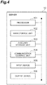
- the server 10 includes a processor 101 that executes an operating system, an application program, or the like, a main storage unit 102 including a ROM and a RAM, an auxiliary storage unit 103 including a hard disk, a flash memory, and the like, a communication control unit 104 including a network card or a wireless communication module, an input device 105 such as a keyboard or a mouse, and an output device 106 such as a display.
- a processor 101 that executes an operating system, an application program, or the like
- main storage unit 102 including a ROM and a RAM
- an auxiliary storage unit 103 including a hard disk, a flash memory, and the like
- a communication control unit 104 including a network card or a wireless communication module
- an input device 105 such as a keyboard or a mouse
- an output device 106 such as a display.
- Each functional component of the server 10 is realized by causing predetermined software to be loaded on the processor 101 or the main storage unit 102 and operating the communication control unit 104, the input device 105, the output device 106, or the like under the control of the processor 101, and mainly reading and writing data in the storage unit 102 or the auxiliary storage unit 103. Data or a database necessary for processing is stored in the main storage unit 102 or the auxiliary storage unit 103.
- the management unit 11 is a functional component for managing identified power transmission levels of one or more power transmitters 91. More specifically, the management unit 11 stores the identified power transmission levels in the database 30 or transmits them to the terminal 20.
- the management unit 11 is realized by the processor 101 executing a management program installed in the server 10, reading and writing data from and to the main storage unit 102 or the auxiliary storage unit 103, and controlling the communication control unit 104.
- the management unit 11 stores records indicating processing results (a power transmitter ID and a power transmission level) received from the power transmitter 91 in the database 30.
- One record indicating the processing result of one power transmitter 91 may include another attribute related to the power transmitter 91.
- the management unit 11 can receive the processing results from the plurality of power transmitters 91, and thus the database 30 can store a plurality of records of the plurality of power transmitters 91.
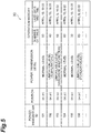
- FIG. 5 illustrates an example of a record stored in the database 30.
- reasons a "temperature,” a "hardware malfunction,” and a “foreign object"
- reasons a "temperature,” a "hardware malfunction,” and a “foreign object”
- reasons a "temperature,” a "hardware malfunction,” and a “foreign object”
- reasons a "temperature,” a "hardware malfunction,” and a “foreign object”
- reasons a "temperature,” a "hardware malfunction,” and a “foreign object”
- the limitation level and the unavailable level are registered as parts of the processing results, but registration of the reasons may be omitted.
- power transmitters 91 whose IDs are "101,” "104,” and “105” can be used without a particular limitation, and a power transmitter 91 whose ID is “102” or “106” is limited at the time of power transmission, and the power transmitter 91 whose ID is "103" cannot be used.
- records include a geographical position where the power transmitter 91 is installed (hereinafter simply referred to as a "position") and an operation history of the power transmitter 91 in addition to the power transmitter ID and the power transmission level.
- position the position of the power transmitter 91 is indicated by two-dimensional coordinates (x, y) represented by latitude and longitude, but a method of representing the position is not limited, and the position may be indicated by another value such as an address.
- the operation history is records of past power transmission of the power transmitter 91.
- the operation history is indicated by a combination of the number of operations and the last operation date and time, but the method of representing the operation history is not limited.
- the operation history may be a set of past operation dates/times, or may be indicated by either the number of operations or the last operation date/time, or may be an average value of the number of operations per unit time (for example, per day).
- This operation history is registered or updated every time power transmission is performed in the power transmitter 91.
- the method of registering/updating the operation history is not limited, and for example, the server 10 may execute a process, or another information processing device may execute a process.
- a method of mounting the database 30 is not limited, and the database 30 may be, for example, a relational database or a CSV file.
- the structure of each record is not limited to the example of FIG. 5 , other items may be included in the record, some of the items illustrated in FIG. 5 may be omitted as required, or any normalization or redundancy may be performed.
- data illustrated in FIG. 5 may be divided into a table indicating a power transmission level of each power transmitter 91 and a table indicating a position and a movement history of each power transmitter 91.
- the management unit 11 can notify the user of the power transmission level of the power transmitter 91 by transmitting the processing result to the terminal 20.
- the management unit 11 may transmit the processing results to the terminal 20 in response to receiving a request from the terminal 20 or may push the processing results to one or more terminals 20 at any timing (for example, periodically) without requiring the reception of the processing results.
- the management unit 11 When receiving the charging request from the terminal 20, the management unit 11 transmits the charging request to at least one power transmitter 91, and receives the processing results sent from each power transmitter 91 in response to this transmission. Then, the management unit 11 transmits one or more received processing results to the terminal 20 as a response to the charging request. The terminal 20 displays the processing results. If the management unit 11 transmits a processing result indicating the position of the power transmitter 91 to the terminal 20, the terminal 20 can display a power transmission level and an address of each power transmitter 91, and the user can determine a power transmitter 91 to be used while viewing information thereof. In order to obtain information about the power transmitter 91 of a specific area only, the charging request may include a current position of the user or the movable object V and a search range (for example, within a radius of 5 km or the like).
- the management unit 11 When not receiving a charging request from the terminal 20, the management unit 11 reads the processing result of each power transmitter 91 from the database 30, and transmits information thereof to the terminal 20. Alternatively, in order to obtain information about the power transmitter 91 in a specific area only, the management unit 11 may receive a request including a current position of the user or the movable object V and a search range from the terminal 20 and transmit only processing results of the power transmitters 91 within an area matching the request as a response to the terminal 20.
- the management unit 11 may transmit information of a power transmitter 91 identified to be at the normal level to the terminal 20 in preference to information of a power transmitter 91 identified to be at the limitation level.
- “transmitting (outputting) certain information (first information) in preference to other information (second information)” means that at least the first information is output so that the user can easily recognize the first information rather than the second information.
- first information certain information
- second information other information
- a technique of realizing the above is not limited, and for example, the management unit 11 may output only the first information without outputting the second information, or both pieces of information may be output after the display order is set so that the first information is displayed before the second information.
- the management unit 11 may transmit only the processing result of a power transmitter 91 whose power transmission level is the normal level. In this case, it is possible to provide the user with guidance of only information of a power transmitter capable of charging the battery of the movable object without any particular limitation.
- the management unit 11 may transmit only the processing results indicating either the normal level or the limitation level. In this case, it is possible to guide users to more chargeable power transmitters.
- the charging request it may be determined that one power transmitter 91 is at the normal level for a certain user and at the limitation level for another user. That is, a power transmitter 91, which does not completely satisfy charging requests of some users, can completely satisfy a charging request of another user.
- a power transmitter 91 which does not completely satisfy charging requests of some users, can completely satisfy a charging request of another user.
- By outputting information of a power transmitter 91 identified to be at the normal level in preference to information of a power transmitter 91 identified to be at the limitation level it is also possible to guide the other user to a power transmitter 91 which does not completely satisfy the charging requests of some users. As a result, it is possible to level off operating rates among a plurality of power transmitters 91 and increase the overall operating rate of the power transmitters 91 in the management system 1.
- the management unit 11 may execute the following processing if there are two or more power transmitters 91 having the same power transmission level. In other words, the management unit 11 first compares operation frequencies obtained from the operation history in the database 30 of the power transmitters 91. Then, the management unit 11 transmits (outputs) information of a power transmitter 91 with a low operation frequency among the two or more power transmitters in preference to information of the remaining power transmitters 91.
- the definition of "preference” is similar to in the above ("outputting at least the first information so that the user can easily recognize the first information rather than the second information").
- the "power transmitter with a low operation frequency” is a power transmitter having a lower operation frequency than at least one power transmitter among the two or more power transmitters.
- Criteria for dividing two or more power transmitters into two groups are not limited.
- the management unit 11 may set a power transmitter other than a power transmitter with a highest operation frequency as the "power transmitter with a low operation frequency.”
- the management unit 11 may set only a power transmitter with a lowest operation frequency as the "power transmitter with a low operation frequency.”
- the management unit 11 may sort two or more power transmitters in ascending order or descending order of the operation frequency, and set about half of the power transmitters with lower operation frequencies as the "power transmitters with a low operation frequency.”
- a method of obtaining the operation frequency is also not limited.
- the management unit 11 may regard the number of operations as the operation frequency as is, or may determine that the operation frequency decreases as the elapsed time from the last operation date/time increases.
- the power transmitters at the normal level are the three power transmitters whose IDs are "101,” “104,” and “105.” If the number of operations is regarded as the operation frequency as is, "105,” “101,” and “104" are shown when the IDs of the three power transmitters are sorted in ascending order of the number of operations.
- the management unit 11 may determine only a power transmitter whose ID is "105” as a “power transmitter with a low operation frequency,” or determine only the two power transmitters whose IDs are “105” and “101” as “power transmitters with a low operation frequency.” If the operation frequency is set on the basis of a length of the elapsed time from the last operation date and time, "104," "101,” and “105” are shown when the IDs of the three power transmitters 91 are sorted in descending order of the elapsed time.
- the management unit 11 may determine only a power transmitter whose ID is "104" as a “power transmitter with a low operation frequency,” or determine only two power transmitters whose IDs are "104" and "101” as “power transmitters with a low operation frequency.”
- the second embodiment is different from the first embodiment in that a server identifies the power transmission level of a power transmitter.
- matters specific to the second embodiment will be described in detail, and description of matters similar to those in the first embodiment will be omitted.
- the management system 1A includes at least a power transmitter 91A and a server 10A, and provides information about the power transmitter 91A to a terminal 20.
- the power transmitter 91A includes a detection unit (for example, a detector) 912A as a functional component.
- the detection unit 912A is realized by a processor executing a management program, reading and writing data from and to a memory, and controlling a sensor and a communication module provided in the power transmitter 91A. Similar to the detection unit 912 in the first embodiment, the detection unit 912A detects any type of state related to the power transmitter 91A. A timing at which the detection unit 912A operates is not limited. For example, the detection unit 912A may detect the state of the power transmitter 91A in response to receiving a detection request from the server 10A.
- the detection unit 912A may detect the state of the power transmitter 91A at any timing (for example, periodically) without receiving an input of a detection request.
- the detection unit 912A generates state information indicating the detected state and transmits the information to the server 10A.
- the state information in the present embodiment further includes an ID of the power transmitter 91A (a power transmitter ID) so that the server 10A can identify a transmission source of the state information.
- the server 10A includes a reception unit (for example, a receiver) 12, an identification unit (for example, a controller) 13, and an output unit (for example, an output device) 14 as functional components and can access a database 30A.
- the database 30A is a device that stores an identification rule 31 used for identifying a power transmission level of the power transmitter 91A and a processing result 32 indicating the identified power transmission level.
- the reception unit 12 is a functional component that receives a charging request from the terminal 20 and outputs the request to the identification unit 13.
- the content and configuration of the charging request are the same as those in the first embodiment.
- the identification unit 13 is a functional component that identifies the power transmission level of the power transmitter 91A corresponding to the state detected by the detection unit 912A of the power transmitter 91A.
- the identification unit 13 is realized by a processor 101 executing a management program installed in the server 10A, reading and writing data from and to the main storage unit 102 or the auxiliary storage unit 103, and controlling the communication control unit 104.
- the identification unit 13 identifies the power transmission level using the identification rules 31.
- the identification unit 13 can identify power transmission levels of the plurality of power transmitters 91A, whereas the identification rules are not always the same among all the power transmitters 91A. Therefore, the identification rules 31 in the present embodiment include the power transmitter ID as a data item, whereby it is possible to distinguish the identification rule of each power transmitter 91A.
- An example of the identification rule 31 in this embodiment is illustrated in FIG. 7 .
- each record of the identification rule 31 may further include the power transmission performance as a data item as illustrated in FIG. 7 .
- a specific value of the identification rule is schematically shown as "Rule Ra” or the like, but the specific content and configuration of each identification rule are similar to those in the first embodiment. Also, the specific content and configuration of the power transmission performance are not limited to the example in FIG. 7 .
- the identification unit 13 When not receiving a charging request from the terminal 20, the identification unit 13 receives the state information from the power transmitter 91A and identifies the power transmission level corresponding to the state information (the power transmitter ID and the detected state) with reference to the identification rule 31. Before this process is executed, the identification unit 13 may transmit a detection request for obtaining the state information from one or more power transmitters 91A to each power transmitter 91A. On the other hand, when receiving a charging request from the terminal 20, the identification unit 13 transmits a detection request to one or more power transmitters 91A in response to the charging request and receives the state information sent from each power transmitter 91A in response to this transmission.
- the identification unit 13 identifies a power transmission level corresponding to the state information (the power transmitter ID and the detected state) with reference to the identification rule 31. In any case, the identification unit 13 outputs the identified power transmission level to the output unit 14 together with the power transmitter ID.
- the output unit 14 is a functional component that outputs a processing result including the input power transmission level and the power transmitter ID.
- the output unit 14 is realized by the processor 101 executing a management program, reading and writing data from and to the main storage unit 102 or the auxiliary storage unit 103, and controlling the communication control unit 104.
- the output unit 14 may transmit the processing result to the terminal 20 without storing the processing result in the database 30A regardless of whether or not the charging request has been received.
- the output unit 14 may store the processing result in the database 30A or may output the processing result to another computer system (not illustrated) other than the management system 1A.
- an output destination of the processing result is not limited as long as a person such as a user of the movable object V or an operator of the management system 1A is eventually able to ascertain a power transmission level of the power transmitter 91A.
- the output unit 14 may read the processing result 32 from the database 30A in response to the charging request received from the terminal 20 and transmit the data to the terminal 20.
- the output unit 14 may receive a request including a current position of the user or the movable object V and a search range from the terminal 20 and transmit only the processing result 32 of the power transmitter 91A within an area that matches the request as a response to the terminal 20 in order to obtain only information about the power transmitter 91A in a specific area.
- a data configuration of the processing result 32 can be set as in the first embodiment ( FIG 5 ).
- the output unit 14 may transmit information of a power transmitter 91A identified to be at the normal level to the terminal 20 in preference to information of a power transmitter 91A identified to be at the limitation level. Alternatively, the output unit 14 may transmit only a processing result indicating either the normal level or the limitation level. Alternatively, if there are two or more power transmitters 91A having the same power transmission level, the output unit 14 may compare operation frequencies obtained from an operation history in the database 30A (processing results 32) among the power transmitters 91A, and transmit (output) information of a power transmitter 91A with a low operation frequency among the two or more power transmitters in preference to information of the remaining power transmitters 91A. In this manner, the priority of output may be set as in the first embodiment and its setting method may vary as in the first embodiment.
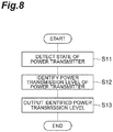
- FIG. 8 is a flowchart illustrating a management method according to the present disclosure to be executed by the management systems 1 and 1A.
- a process shown in this flowchart is started when the management system 1 or 1A acquires a charging request from the terminal 20 or when a predetermined execution time has been reached without receiving a charging request
- a state of the power transmitter 91 or 91A is detected and state information is obtained (step S11, detection step).
- a power transmission level of the power transmitter 91 or 91A is identified by referring to an identification rule using the state information (step S12, identification step).
- the identified power transmission level is output (step S13, output step).
- the management system 1 or 1A Before the power transmission of the power transmitter 91 or 91A is started (in other words, before power feeding to the power receiver 92 of the movable object V is started), the management system 1 or 1A outputs a power transmission level of the power transmitter 91 or 91A.
- step S13 is executed before the power transmission is started, and the processing of steps S11 and S12, which is the prerequisite for the processing of step S13, is also executed before the start of the power transmission.
- a device that executes the processing of each step is not limited.
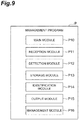
- the management program P includes a main module P10, a reception module P11, a detection module P12, a storage module P13, an identification module P14, an output module P15, and a management module P16.
- the main module P10 is a part that centrally controls the management of the power transmission level of the power transmitter.
- the functions realized by executing the reception module P11, the detection module P12, the storage module P13, the identification module P14, the output module P15, and the management module P16 are similar to those of the reception unit, the detection unit, the storage unit (or the database), the identification unit, the output unit, and the management unit in each embodiment described above. If functional components are divided among a plurality of computers as in the above embodiments, necessary modules are provided in each computer. In the management program P corresponding to the second embodiment, the management module P16 may be omitted.
- the management program P may be provided after being fixedly recorded on a tangible recording medium such as a CD-ROM, a DVD-ROM, a semiconductor memory, or the like. Alternatively, the management program P may be provided via a communication network as a data signal superimposed on carrier waves.
- a management system for a power transmitter capable of wirelessly transmitting power to a power receiver of a movable object, the management system including: a detection unit configured to detect a state of the power transmitter, a storage unit configured to store a relationship between the state of the power transmitter and a power transmission level indicating possibility of power transmission of the power transmitter; an identification unit configured to identify the power transmission level corresponding to the state detected by the detection unit with reference to the storage unit; and an output unit configured to output the power transmission level identified by the identification unit before the power transmitter starts transmitting power, wherein the power transmission level includes at least an unavailable level indicating that power transmission is impossible, a limitation level indicating that power transmission is possible under a predetermined limitation, and a normal level indicating that power transmission is possible without limitation.
- a management method is a management method to be executed by a management system for a power transmitter capable of wirelessly transmitting power to a power receiver of a movable object, the management method including: a detection step of detecting a state of the power transmitter; an identification step of identifying a power transmission level corresponding to the state detected in the detection step with reference to a storage unit storing a relationship between the state of the power transmitter and a power transmission level indicating possibility of power transmission of the power transmitter; and an output step of outputting the identified power transmission level in the identification step before the power transmitter starts transmitting power, wherein the power transmission level includes at least an unavailable level indicating that power transmission is impossible, a limitation level indicating that power transmission is possible under a predetermined limitation, and a normal level indicating that power transmission is possible without limitation.
- a management program is a management program for causing a computer system including one or more computers to function as a management system for a power transmitter capable of wirelessly transmitting power to a power receiver of a movable object, wherein the management program causes the computer system to function as: a detection unit configured to detect a state of the power transmitter; a storage unit configured to store a relationship between the state of the power transmitter and a power transmission level indicating possibility of power transmission of the power transmitter; an identification unit configured to identify the power transmission level corresponding to the state detected by the detection unit with reference to the storage unit; and an output unit configured to output the power transmission level identified by the identification unit before the power transmitter starts transmitting power, and wherein the power transmission level includes at least an unavailable level indicating that power transmission is impossible, a limitation level indicating that power transmission is possible under a predetermined limitation, and a normal level indicating that power transmission is possible without limitation.
- a mode of power transmission is output in at least three steps such as an unavailable level (at which power transmission is impossible), a limitation level (at which limited power transmission is possible), and a normal level (at which power transmission is possible without limitation) according to a state of the power transmitter before the start of power feeding. It is possible to provide the mode of power transmission by the power transmitter in more detail by enabling a mode in which limited power transmission is possible to be output, in addition to the two modes of whether normal power transmission is possible or impossible. By outputting not only a normal level which can be said to be in an ideal state but also a limitation level considered to satisfy a certain requirement of the user, it is possible to guide the user to a power transmitter which can actually transmit electric power.
- the identification unit may identify the power transmission level on the basis of both a charging request related to charging of the movable object and acquired from a predetermined device and the detected state. By further considering the request for charging the movable object, it is possible to identify the power transmission level according to a situation of each movable object which is a target to which power is transmitted.
- the power transmitter may include the detection unit, the identification unit, and the output unit.
- the power transmitter can identify and output the power transmission level of the power transmitter without using an intermediary device such as a server.
- each of a plurality of power transmitters may include the detection unit, and a server capable of communicating with the plurality of power transmitters may include the identification unit and the output unit, whereby the server identifies the power transmission level for each of the plurality of power transmitters.
- a terminal user
- the server manages the power transmission level of the plurality of power transmitters, a terminal (user) can efficiently acquire the power transmission levels of the plurality of power transmitters without accessing the individual power transmitters. This can lead to a reduction in an amount of data flowing through the communication network.
- the output unit may output information of a power transmitter identified to be at the normal level in preference to the information of a power transmitter identified to be at the limitation level. In this case, it is possible to preferentially provide the user with information on a power transmitter that can transmit power without any particular limitation. If the power transmission level is identified in further consideration of the charging requests, a power transmitter identified to be at the limitation level for a first user (movable object) may be identified to be at the normal level for a second user (movable object). In this case, the information of the power transmitter is preferentially provided to the second user (movable object). A power transmitter that does not completely satisfy the charging request of some users (mobile objects) can completely satisfy the charging request of another user (movable object). It is possible to level off operating rates between a plurality of power transmitters in consideration of individual charging requests in this aspect. Additionally, an increase in the overall operating rate of the power transmitters in the management system can be expected.
- the management system may further include a database configured to store an operation history of a plurality of power transmitters, wherein the output unit may compare an operation frequency obtained from the operation history stored in the database of two or more power transmitters when the two or more power transmitters having the same power transmission level are present and output information of a power transmitter with a lower or lowest operation frequency among the two or more power transmitters in preference to information of the remaining power transmitters among the two or more power transmitters.
- the output unit may transmit the identified power transmission level of a power transmitter to a terminal of a user of the movable object together with a position of the power transmitter, whereby the terminal may display the power transmission level and the position of the power transmitter.
- the management system also has a function of transmitting information on the power transmitter to the user terminal, but this transmission function is not indispensable. Therefore, the function of guiding the user to a specific power transmitter is also not indispensable.
- the management system provides the processing result to the user terminal, but the management system may provide the processing result to a device other than the user terminal (for example, a power receiver, an information processor outside the management system, and the like).
- a device other than the user terminal for example, a power receiver, an information processor outside the management system, and the like.
- the management system includes a database, but an arrangement method of the database is not limited thereto.
- this database may be in another information processing system different from the management system, or the database may be constructed in the server.
- a position of the database is not limited at all as long as a device in the management system can access the database via a communication network.
- the database is not an essential component.
- a mode of power transmission by the power transmitter can be provided in more detail before the start of power feeding.
Landscapes
- Engineering & Computer Science (AREA)
- Power Engineering (AREA)
- Transportation (AREA)
- Mechanical Engineering (AREA)
- Computer Networks & Wireless Communication (AREA)
- Life Sciences & Earth Sciences (AREA)
- Sustainable Development (AREA)
- Sustainable Energy (AREA)
- Charge And Discharge Circuits For Batteries Or The Like (AREA)
- Electric Propulsion And Braking For Vehicles (AREA)
Abstract
Description
- The present disclosure relates to a system, method, and program for managing a power transmitter. This application is based upon and claims the benefit of priority from Japanese Patent Application No.
2015-105345, filed on May 25, 2015 - Conventionally, a movable object (for example, an electric vehicle) including a rechargeable battery as at least a part of a power source is known. Such a movable object needs to receive power at a charging station if the remaining power of the battery becomes small. In relation to this, a mechanism for managing a state of a power transmitter that supplies power to the movable object is known.
- For example, the following Patent Literature 1 describes a wireless power transfer device capable of detecting a malfunction. Specifically, a detection unit of the wireless power transfer device detects a phase difference between an output voltage and an output current output from a power supply main circuit, and a power supply side controller provides a notification indicating a malfunction using a notification device when it is determined that the phase difference is outside a specific range.
- Also, in the following Patent Literature 2, a power feeding device including a warning device is described. Specifically, a power transmission ECU determines the presence or absence of a malfunction of a primary resonance coil on the basis of a signal indicating the state of the primary resonance coil detected by a detector and the warning device provides a notification of the presence/absence of a malfunction.
-
- [Patent Literature 1]
JP 2013-115833 A - [Patent Literature 2]
JP 2012-055109 A - All mechanisms described in the above-described patent literature determine whether power feeding is possible or impossible. However, the power transmitter of the wireless power transfer system may be able to perform limited power transmission even if normal power transmission (that is, unlimited power transmission) cannot be performed. There can also be demand for limited power transmission. For example, although a temperature in the device may be in an allowable range, the temperature may exceed the allowable range if normal power transmission is executed. In this case, although a power transmission time is limited, it is not impossible to transmit power. This is one aspect of limited power transmission, and there may be users who wish to receive charging while allowing this limitation. In a conventional dichotomous mechanism, such limited power transmission is handled as either possible power transmission or impossible power transmission. However, in this case, limited power transmission cannot be distinguished from normal power transmission or impossible power transmission. For example, if limited power transmission is determined to be impossible, the chance for power feeding is reduced, and the time until completion of desired charging is prolonged. It is therefore desired to provide a mode of power transmission by the power transmitter in more detail before the start of power feeding.
- A management system according to an aspect of the present disclosure is a management system for a power transmitter capable of wirelessly transmitting power to a power receiver of a movable object, the management system including: a detection unit configured to detect a state of the power transmitter; a storage unit configured to store a relationship between the state of the power transmitter and a power transmission level indicating possibility of power transmission of the power transmitter; an identification unit configured to identify the power transmission level corresponding to the state detected by the detection unit with reference to the storage unit; and an output unit configured to output the power transmission level identified by the identification unit before the power transmitter starts transmitting power, wherein the power transmission level includes at least an unavailable level indicating that power transmission is impossible, a limitation level indicating that power transmission is possible under a predetermined limitation, and a normal level indicating that power transmission is possible without limitation.
- According to an aspect of the present disclosure, a mode of power transmission by the power transmitter can be provided in more detail before the start of power feeding.
-
-
FIG. 1 is a diagram schematically illustrating a case in which a management system according to an embodiment is applied. -
FIG. 2 is a block diagram illustrating a functional configuration of a management system according to a first embodiment. -
FIG. 3 is a graph illustrating an example of an identification rule. -
FIG. 4 is a diagram illustrating a hardware configuration of a server. -
FIG. 5 is a diagram illustrating an example of processing results. -
FIG. 6 is a block diagram illustrating a functional configuration of a management system according to a second embodiment. -
FIG. 7 is a diagram illustrating a concept of an identification rule used in the second embodiment. -
FIG. 8 is a flowchart illustrating operations of the management systems according to the first and second embodiments. -
FIG. 9 is a diagram illustrating a configuration of a management program according to an embodiment. - A management system according to an aspect of the present disclosure is a management system for a power transmitter capable of wirelessly transmitting power to a power receiver of a movable object, the management system including: a detection unit configured to detect a state of the power transmitter; a storage unit configured to store a relationship between the state of the power transmitter and a power transmission level indicating possibility of power transmission of the power transmitter; an identification unit configured to identify the power transmission level corresponding to the state detected by the detection unit with reference to the storage unit; and an output unit configured to output the power transmission level identified by the identification unit before the power transmitter starts transmitting power, wherein the power transmission level includes at least an unavailable level indicating that power transmission is impossible, a limitation level indicating that power transmission is possible under a predetermined limitation, and a normal level indicating that power transmission is possible without limitation.
- A management method according to an aspect of the present disclosure is a management method to be executed by a management system for a power transmitter capable of wirelessly transmitting power to a power receiver of a movable object, the management method including: a detection step of detecting a state of the power transmitter; an identification step of identifying a power transmission level corresponding to the state detected in the detection step with reference to a storage unit storing a relationship between the state of the power transmitter and a power transmission level indicating possibility of power transmission of the power transmitter; and an output step of outputting the identified power transmission level in the identification step before the power transmitter starts transmitting power, wherein the power transmission level includes at least an unavailable level indicating that power transmission is impossible, a limitation level indicating that power transmission is possible under a predetermined limitation, and a normal level indicating that power transmission is possible without limitation.
- A management program according to an aspect of the present disclosure is a management program for causing a computer system including one or more computers to function as a management system for a power transmitter capable of wirelessly transmitting power to a power receiver of a movable object, wherein the management program causes the computer system to function as: a detection unit configured to detect a state of the power transmitter; a storage unit configured to store a relationship between the state of the power transmitter and a power transmission level indicating possibility of power transmission of the power transmitter; an identification unit configured to identify the power transmission level corresponding to the state detected by the detection unit with reference to the storage unit; and an output unit configured to output the power transmission level identified by the identification unit before the power transmitter starts transmitting power, and wherein the power transmission level includes at least an unavailable level indicating that power transmission is impossible, a limitation level indicating that power transmission is possible under a predetermined limitation, and a normal level indicating that power transmission is possible without limitation.
- In this aspect, a mode of power transmission is output in at least three steps such as an unavailable level (at which power transmission is impossible), a limitation level (at which limited power transmission is possible), and a normal level (at which power transmission is possible without limitation) according to a state of the power transmitter before the start of power feeding. It is possible to provide the mode of power transmission by the power transmitter in more detail by enabling a mode in which limited power transmission is possible to be output, in addition to the two modes of whether normal power transmission is possible or impossible.
- In the management system according to another aspect, the identification unit may identify the power transmission level on the basis of both a charging request related to charging of the movable object and acquired from a predetermined device and the detected state. By further considering the request for charging the movable object, it is possible to identify the power transmission level according to a situation of each movable object which is a target to which power is transmitted.
- In the management system according to another aspect, the power transmitter may include the detection unit, the identification unit, and the output unit. In this case, the power transmitter can identify and output the power transmission level of the power transmitter without using an intermediary device such as a server.
- In the management system according to another aspect, each of a plurality of power transmitters may include the detection unit, and a server capable of communicating with the plurality of power transmitters may include the identification unit and the output unit, whereby the server identifies the power transmission level for each of the plurality of power transmitters. In this case, because the server manages the power transmission level of the plurality of power transmitters, a terminal (user) can efficiently acquire the power transmission levels of the plurality of power transmitters without accessing the individual power transmitters.
- In the management system according to another aspect, the output unit may output information of a power transmitter identified to be at the normal level in preference to information of a power transmitter identified to be at the limitation level. In this case, it is possible to preferentially provide the user with information of a power transmitter that can transmit power without any particular limitation. If the power transmission level is identified in further consideration of the charging requests, a power transmitter identified to be at the limitation level for a first user (movable object) may be identified to be at the normal level for a second user (movable object). In this case, the information of the power transmitter is preferentially provided to the second user (movable object). A power transmitter that does not completely satisfy charging requests of some users (mobile objects) can completely satisfy the charging request of another user (movable object). It is possible to level off operating rates between a plurality of power transmitters in consideration of individual charging requests in this aspect. Additionally, an increase in the overall operating rate of the power transmitters in the management system can then be expected.
- The management system according to another aspect may further include a database configured to store an operation history of a plurality of power transmitters, wherein the output unit may compare an operation frequency obtained from the operation history stored in the database of two or more power transmitters when the two or more power transmitters having the same power transmission level are present and output information of a power transmitter with a lower or lowest operation frequency among the two or more power transmitters in preference to information of the remaining power transmitters among the two or more power transmitters. By preferentially providing information of a power transmitter with a low operation frequency, it is possible to level off operating rates between the plurality of power transmitters and an increase in the overall operating rate of the power transmitters in the management system can be expected.
- In the management system according to another aspect, the output unit may transmit the identified power transmission level of a power transmitter to a terminal of a user of the movable object together with a position of the power transmitter, whereby the terminal may display the power transmission level and the position of the power transmitter. By presenting the power transmission level and position of the power transmitter to the user in this way, it is possible to guide the user to a power transmitter identified to be convenient for the user.
- Hereinafter, embodiments of the present disclosure will be described in detail with reference to the accompanying drawings. Also, in the description of the drawings, the same or equivalent elements are denoted by the same reference signs, and redundant description thereof will be omitted.
- A function and configuration of the management system 1 according to the first embodiment will be described with reference to
FIGS. 1 to 5 . The management system 1 is a computer system that manages a power transmitter capable of wirelessly transmitting power to a power receiver of a movable object. In the present embodiment, the management system 1 also plays a role of guiding the user of the movable object to a specific power transmitter. - The "movable object" is a device that transports people or objects from one place to another. The movable object includes a rechargeable battery (hereinafter simply referred to as a "battery") as at least a part of a power source. In the present embodiment, an electric vehicle is shown as an example of the movable object, but the type of movable object is not limited at all, and it may be, for example, a motorcycle, a bicycle, a train, an on-water navigation object, an underwater navigation object, or an airplane. Therefore, a route along which the movable object travels may be a land road, a waterway, or an air route.
- The "user of the movable object" (hereinafter also simply referred to as the "user") is a person who wants to know information on a power transmitter in order to charge a battery of the movable object. The user may be a driver or a pilot of the movable object, a passenger of the movable object, or a person who is not in the movable object.
- A position where the power transmitter is provided is not limited, and can be a public facility such as a charging station or a parking lot. Because the type of movable object is not limited, the position where the power transmitter is provided is also not limited. For example, the power transmitter can be installed along a road or may be installed in a port, an airport, or the like.
- In
FIG. 1 , an example in which the management system 1 is applied is schematically illustrated. The management system 1 includes at least apower transmitter 91 of a wirelesspower transfer system 90. Although only onepower transmitter 91 is illustrated inFIG. 1 , the management system 1 may include a plurality ofpower transmitters 91. In order to provide information about thepower transmitter 91 to a terminal 20, the management system 1 may further include aserver 10. Thepower transmitter 91, theserver 10, and the terminal 20 can transmit and receive data to and from each other via a communication network N. The configuration of the communication network N is not limited at all, and the communication network N may be constructed by any communication network such as the Internet or an intranet. - The wireless
power transfer system 90 includes thepower transmitter 91 and apower receiver 92, and wirelessly supplies electric power from thepower transmitter 91 to thepower receiver 92 using magnetic coupling between the coils, such as a magnetic field resonance method or an electromagnetic induction method. Thepower transmitter 91 includes a transmission power conversion device (for example, a rectification circuit, a DC/DC converter, an inverter circuit, or the like) 91a and a power transmission coil device 91b. Thepower receiver 92 includes a power reception coil device 92a and a received power conversion device (for example, a rectification circuit, a DC/DC converter, or the like) 92b, and is mounted on a movable object V. The electric power sent to thepower receiver 92 is accumulated in abattery 93 of the movable object V. Both thepower transmitter 91 and thepower receiver 92 include hardware elements such as a processor, a memory, an input/output interface, a communication interface, and the like. Also, a method of wirelessly transmitting power is not limited to a magnetic field resonance method and an electromagnetic induction method, and other methods such as an electromagnetic coupling method and a radio wave method may be used. - The
server 10 is a computer that manages information about thepower transmitter 91. For example, theserver 10 can be a server of a guidance system such as a car navigation system. Although only oneserver 10 is illustrated inFIG. 1 , the management system 1 may include a plurality ofservers 10. - The terminal 20 is a computer that displays information about the
power transmitter 91 to the user, and is also referred to as a user terminal. The type of computer used as the terminal 20 is not limited, and the terminal 20 may or may not be mounted on the movable object V. For example, the terminal 20 may be a car navigation system, or a portable terminal such as a high-function portable phone (smartphone), a portable phone, a portable information terminal (PDA), a tablet, a laptop personal computer, or the like. If the terminal 20 is not mounted on the movable object V, the terminal 20 may or may not be connectable to the system in the movable object V. Although only oneterminal 20 is shown inFIG 1 , the management system 1 may include a plurality ofterminals 20. - The management system 1 identifies the power transmission level of the
power transmitter 91 and outputs an identification result. The management system 1 may identify and output the power transmission level in response to a charging request from the terminal 20 or may identify and output the power transmission level without acquiring the charging request. Thepower transmitter 91 may directly receive the charging request from the terminal 20 or may receive it via theserver 10. Also, thepower transmitter 91 may directly transmit the processing result (the identified power transmission level) to the terminal 20 or may transmit the processing result via theserver 10. The management system 1 may temporarily store the processing result in thedatabase 30 and may transmit the processing result read from thedatabase 30 to the terminal 20 or may directly transmit the processing result to the terminal 20 without storing the processing result in thedatabase 30. As described above, a timing at which the power transmission level is identified and the method of data transmission/reception between the devices are not limited at all. Representative aspects will be exemplified below. - The "power transmission level" is an index indicating a possibility of power transmission by the power transmitter (in other words, a possibility of supplying power from the power transmitter to the power receiver). The power transmission level not only indicates whether or not power transmission is possible, but also indicates how much power can be transmitted when power transmission is possible. In the present embodiment, the power transmission level includes at least three levels such as an unavailable level, a limitation level, and a normal level, and one power transmission level is identified from a plurality of candidates. The unavailable level means that power transmission is impossible. The limitation level means that power transmission is possible under a predetermined limitation. The normal level means that power transmission is possible without limitation. For example, the normal level indicates that power transmission according to specifications of the power transmitter is possible.
- The "limitation" for distinguishing the limitation level from the normal level is a concept determined only by a relative relationship between these two types of level. That is, "no limitation" at the normal level means that there is no limitation applied at the limitation level, but does not mean that the power transmission can be completely and unlimitedly performed. For example, if the power itself provided to the
power transmitter 91 is limited, there may be a case in which thebattery 93 of the movable object V cannot be fully charged even at a normal level. - A type of limitation that exists at the limitation level and does not exist at the normal level is not limited. Examples of such a limitation may include a limitation related to power (whose unit is kilowatts (kW)), a Limitation related to a possible power transmission time (whose unit is hours (h)), a limitation related to an amount of power (whose unit is kilowatt-hours (kWh)), and a limitation related to power efficiency (%). Alternatively, limits based on combinations of any plurality of parameters selected from these parameters may be used. Furthermore, limits based on other parameters different from these parameters may be used.
- For example, if the power (normal power) guaranteed at the normal level is denoted by PN, a power range of PLmin to PLmax guaranteed at the limitation level is less than PN. Here, the value PLmin is a minimum value of the power at the limitation level, and the value PLmax is a maximum value of the power at the limitation level. If the guaranteed power is less than PLmin, the power transmission level is the unavailable level.
- For example, if the possible power transmission time (normally possible time) guaranteed at the normal level is greater than or equal to HNmin, a range HLmin to HLmax of the possible power transmission time guaranteed at the limitation level is less than HNmin. Here, the value HLmin is a minimum value of the possible power transmission time at the limitation level, and the value HLmax is a maximum value of the possible power transmission time at the limitation level. If the guaranteed possible power transmission time is less than HLmin, the power transmission level is the unavailable level.
- For example, if the amount of power guaranteed at the normal level (normal amount of power) is greater than or equal to WNmin, a range of WLmin to WLmax of the amount of power guaranteed at the limitation level is less than WNmin. Here, the value WLmin is a minimum value of the amount of power at the limitation level, and the value WLmax is a maximum value of the amount of power at the limitation level. If the amount of power guaranteed is less than WLmin, the power transmission level is the unavailable level.
- For example, if the power efficiency (normal efficiency) guaranteed at the normal level is ENmin or more, a power efficiency range of ELmin to ELmax guaranteed at the limitation level is less than ENmin. Here, the value ELmin is a minimum value of the power efficiency at the limitation level, and the value ELmax is a maximum value of the power efficiency at the limitation level. If the guaranteed power efficiency is less than ELmin, the power transmission level is the unavailable level.
- At least one of the normal level and the limitation level may further be subdivided into a plurality of levels on the basis of any parameter. For example, assuming that a minimum amount of power guaranteed at the normal level is denoted by WNa and WNb (>WNa) is further set as the amount of power at the normal level, the normal level Na at which the amount of power is greater than or equal to WNa and less than WNb and the normal level Nb at which the amount of power is greater than or equal to WNb can be set. At this time, the amount of power at the limitation level is naturally necessarily limited to less than WNa. In another example, if the range of HLmin to HLmax of the possible power transmission time guaranteed at the limitation level is divided into a range Ra that is greater than or equal to HLmin and less than HLa, a range Rb that is greater than or equal to HLa and less than HLb, and a range Rc that is greater than or equal to HLb and less than or equal to HLmax, a limitation level La corresponding to the range Ra, a limitation level Lb corresponding to the range Rb, and a limitation level Lc corresponding to the range Rc are set.
- The "charging request" is information indicating a request relating to charging the
battery 93 of the movable object V. Specific content of the charging request is not limited, and may be, for example, the current remaining power (state of charge (SOC)) of the battery, a necessary or desired amount of charging, or a charging time. For example, the charging request may indicate the SOC being changed from the current 30% to 100%, that a time period capable of being spent on charging is at most 1 hour, or the SOC being increased from the current 40% to 80% within 2 hours. - Next, a functional configuration of the
power transmitter 91 will be described. As illustrated inFIG 2 , thepower transmitter 91 includes a reception unit (for example, a receiver) 911, a detection unit (for example, a detector) 912, a storage unit (for example, a memory) 913, an identification unit (for example, a controller) 914, and an output unit (for example, an output device) 915 as functional components. These functional components are realized by a processor executing a management program installed in thepower transmitter 91 to control hardware elements such as a memory and a communication interface. - The
reception unit 911 is a functional component that receives a charging request from the terminal 20 or theserver 10. Thereception unit 911 is realized by the processor executing the management program, reading and writing data from and to the memory, and controlling the communication interface. Thereception unit 911 outputs the received charging request to thedetection unit 912. - The
detection unit 912 is a functional component that detects the state of thepower transmitter 91. Thedetection unit 912 is realized by a processor executing the management program, reading and writing data from and to the memory, and controlling the sensor provided in thepower transmitter 91. - The "state of the power transmitter" is a state inside or outside the power transmitter at a certain point in time. A type of detected state is not limited.
- For example, the
detection unit 912 may detect states of hardware elements such as circuits in the power transmitter 91 (for example, an inverter circuit, a rectification circuit, a resonance circuit, and a communication circuit), a device attached to the power transmitter 91 (for example, a foreign object detection device), or the like. By incorporating a current/voltage sensor in thepower transmitter 91, thedetection unit 912 can detect whether these hardware elements are normal or abnormal (for example, short circuit, element breakage, and sensor failure) or detect the operational situation of the hardware elements. - Alternatively, the
detection unit 912 may detect a temperature in thepower transmitter 91. Here, the temperature in the power transmitter may be a temperature of an internal space of thepower transmitter 91, or a temperature of a specific component of the power transmitter 91 (an element temperature of each circuit, a ferrite temperature of the resonance circuit, or the like). By incorporating a temperature sensor in thepower transmitter 91, thedetection unit 912 can detect a temperature. - Alternatively, the
detection unit 912 may detect a foreign object existing around thepower transmitter 91. Here, the "foreign object" is an object that may reduce power efficiency or impede power transmission. For example, thedetection unit 912 may detect a foreign object that is likely to be present between thepower transmitter 91 and thepower receiver 92. Thedetection unit 912 can detect the foreign object by providing a foreign object detection coil formed by a conductive wire as thedetection unit 912 in thepower transmitter 91 and detecting the disturbance of a magnetic flux connected with a coil as a change in an induced voltage. Also, it can be determined that the power efficiency decreases as the change in the induced voltage of the detection unit 912 (hereinafter also simply referred to as the "change in the induced voltage") increases. - A timing at which the
detection unit 912 operates is not limited. For example, thedetection unit 912 may detect the state of thepower transmitter 91 in response to an input of a charging request from thereception unit 911 or may detect the state of thepower transmitter 91 at any timing (for example, periodically) without receiving the input of the charging request. - The
detection unit 912 generates state information indicating the detected state and outputs the information to theidentification unit 914. If the charging request has been input, thedetection unit 912 outputs the state information to theidentification unit 914 together with the charging request. A method of representing the state information may be arbitrarily defined. For example, the state information may be represented in binary (for example, "0" or "1") or the measured value may be used as the state information as it is. As an example, whether the hardware element is normal or abnormal and whether or not there is a foreign object can be represented in binary, and the temperature can be represented by a measured value. - The
storage unit 913 is a functional component that stores a relationship between the state of thepower transmitter 91 and the power transmission level and is realized by a memory. The "relationship between the state of the power transmitter and the power transmission level" is a rule used to identify the power transmission level from the state of the power transmitter, and this rule is referred to as an "identification rule" below. Thestorage unit 913 stores data or an algorithm indicating this relationship (the identification rule). A method of representing the identification rule is not limited. For example, identification rules may be represented by a correspondence table illustrating the correspondence relationship between the state of thepower transmitter 91 and the power transmission level. Alternatively, the identification rules may be represented by a predetermined algorithm for calculating the power transmission level without using a correspondence table. In any case, by using the identification rules, one power transmission level is identified when the state of thepower transmitter 91 is given as a condition. - As described above, because the state and the power transmission level of the
power transmitter 91 may all vary, various relationships between the state and the power transmission level can be set. Therefore, the content of the identification rules is not limited at all. Hereinafter, some examples of identification rules are shown. - The
storage unit 913 may store a correspondence relationship between the state of the hardware element in thepower transmitter 91 and the power transmission level as an identification rule. For example, thestorage unit 913 may store a correspondence table illustrating the following relationships Ra1 to Ra3. - Ra1: Normal level if all circuits in the device are normal.
- Ra2: Limit level if circuits (for example, an inverter circuit, a rectification circuit, and a resonance circuit) essential for power transmission are all normal, but a circuit which is not directly involved in power transmission (for example, a communication circuit) is abnormal.
- Ra3: Unavailable level if there is a malfunction in any circuit essential for power transmission.
- Alternatively, a case in which there is a malfunction in a communication circuit which is not directly involved in power transmission may correspond to the normal level. As still another example, if a circuit essential for power transmission is duplicated and a backup system is operating instead of the normal system, this state may be made to correspond to the limitation level.
- The
storage unit 913 may store a relationship between a temperature in the power transmitter 91 (hereinafter also simply referred to as a "temperature") and the power transmission level as an identification rule. Because the power transmission function of thepower transmitter 91 is not exerted when the detected temperature exceeds the allowable range, the management system 1 determines that power transmission is impossible. When the temperature in thepower transmitter 91 is expected to exceed the allowable range merely by performing the power transmission for a relatively short time even if the detected temperature is in the allowable range, the management system 1 limits a power transmission time. In order to make such a determination, thestorage unit 913 stores a relationship between the power transmission time and a temperature rise in thepower transmitter 91. Because the amount of power is proportional to time, the relationship between an amount of supplied power and the temperature rise can also be shown like the relationship between the time and the temperature rise. Therefore, thestorage unit 913 may store the relationship between the amount of supplied power from thepower transmitter 91 and the temperature rise. -
FIG. 3 is a graph illustrating an example of such a relationship, wherein the vertical axis represents a temperature (°C) and the horizontal axis represents a time (h) or an amount of power (kWh). This graph shows a change in temperature in a case in which thepower transmitter 91 is continuously operated from the time at which a temperature in thepower transmitter 91 is a standard value tA. A value tL is a limit value of the allowable range of the temperature, and it is determined that power transmission from thepower transmitter 91 is impossible if the temperature exceeds the value tL. If a temperature at the time of the start of power transmission is tA, a maximum power transmission time is hA (or the maximum amount of supplied power is pA). If the temperature at the time of the start of power transmission is tB greater than tA for a reason such as a short elapsed time from the last power feeding, the possible power transmission time is hB shorter than hA (or an amount of power capable of being supplied is pB smaller than pA). If the temperature is tB and the time required for charging or the required charging time is longer than hB, the power transmission level is identified to be the limitation level. Even if the temperature is tB, when the time required for charging or the required charging time is less than or equal to hB, the power transmission level is identified to be the normal level. Such identification is also similar for the amount of electric power. Thus, it can be said that the relationship between the temperature and the power transmission level is determined by a relationship between the detected temperature and the desired charging time or power amount. Thestorage unit 913 stores identification rules as shown in the graph ofFIG 3 in the form of data, functions, programs, or the like. - The
storage unit 913 may store a correspondence relationship between the presence of a foreign object around thepower transmitter 91 and a power transmission level as an identification rule. For example, thestorage unit 913 may store a correspondence table indicating the following relationships Rb1 to Rb3. - Rb1: Normal level if there is no foreign object.
- Rb2: Limit level if there is a foreign object, but a change in an induced voltage is less than a threshold value Ta.
- Rb3: Unavailable level if there is a foreign object for which the change in the induced voltage is greater than or equal to the threshold value Ta.
- The
storage unit 913 may store a relationship between a plurality of types of state in thepower transmitter 91 and a power transmission level as an identification rule. For example, thestorage unit 913 may store a correspondence table illustrating the following relationships Rc1 to Rc3. - Rc1: Normal level if all circuits in the device are normal and there is no foreign object.
- Rc2: Limit level if circuits (for example, communication circuits) which are not directly involved in power transmission are abnormal even though circuits (for example, the inverter circuit, the rectification circuit, and the resonance circuit) essential for power transmission are all normal, or if a change in an induced voltage for a foreign object is less than Ta even though a foreign object is present.
- Rc3: Unavailable level if there is a malfunction in any of the circuits essential for power transmission, or there is a foreign object for which a change in an induced voltage is greater than or equal to the threshold value Ta.
- Alternatively, the
storage unit 913 may store a correspondence table indicating the following relationships Rd1 to Rd4. Also, a first limitation level is assumed to have a more relaxed limitation related to power transmission than a second limitation level. - Rd1: Normal level if all circuits in the device are normal and there is no foreign object
- Rd2: First limitation level if a change in an induced voltage for a foreign object is less than Ta even though a foreign object exists.
- Rd3: Second limitation level if circuits (for example, the inverter circuit, the rectification circuit, and the resonance circuit) essential for power transmission are all normal, but a circuit which is not directly involved in power transmission (for example, the communication circuit) is abnormal.
- Rd4: Unavailable level if there is a malfunction in any of the circuits essential for power transmission, or there is a foreign object for which a change in an induced voltage is greater than or equal to the threshold value Ta.
- The
storage unit 913 may further store device information indicating a power transmission performance of thepower transmitter 91. This device information can be used as an additional or ancillary parameter when identifying the power transmission level using an identification rule. The power transmission performance includes an output voltage, an output current, a charging time, and the like, but the parameters indicating the power transmission performance are not limited thereto. For example, when a power transmission parameter is identified from the temperature in thepower transmitter 91, the output voltage and the output current can be used when a required amount of power is obtained from a charging time indicated in the charging request. - The
identification unit 914 is a functional component for identifying the power transmission level of thepower transmitter 91 corresponding to the state detected by thedetection unit 912. "Identification" is a process of deriving one power transmission level, and a specific method thereof is not limited. For example, both a process of identifying one power transmission level using a correspondence table and a process of obtaining a power transmission level using any algorithm are included in the concept of "identification." Theidentification unit 914 outputs the identified power transmission level to theoutput unit 915. Theidentification unit 914 is realized by a processor executing the management program and reading and writing data from and to the memory. - If no charging request has been input and only state information has been input, the
identification unit 914 identifies a power transmission level corresponding to the state information with reference to the identification rules stored in thestorage unit 913. For example, assuming that thestorage unit 913 stores the relationships Ra1 to Ra3 and state information indicating a malfunction of the communication circuit is assumed to have been input, theidentification unit 914 identifies that the power transmission level of thepower transmitter 91 is the limitation level. In another example, thestorage unit 913 is assumed to store the relationship between the temperature and the power transmission time or the amount of supplied power illustrated inFIG. 3 as an identification rule. In this case, theidentification unit 914 may identify the power transmission level by applying a predetermined default value of a power transmission time or an amount of supplied power to an identification rule (for example, a time or an amount of power required for causing the SOC to become 100% from 0%). For example, when the temperature indicated by the state information is tX (<tL) and the default value of the power transmission time or the amount of supplied power is applied to the identification rule illustrated inFIG 3 , theidentification unit 914 identifies that the power transmission level is the limitation level if the temperature exceeds tL. If the temperature indicated by the state information is greater than or equal to tL, theidentification unit 914 identifies that the power transmission level is the unavailable level. Alternatively, assuming that thestorage unit 913 stores the above-described relationships Rb1 to Rb3, theidentification unit 914 identifies that the power transmission level of thepower transmitter 91 is the unavailable level if state information indicating the presence of a foreign object for which a change in the induced voltage is a value D (where D≥Ta) is assumed to have been input. - If a charging request has also been input in addition to the state information, the
identification unit 914 may further identify the power transmission level on the basis of the charging request. However, if it is identified that the power transmission level is the unavailable level on the basis only of the state information, theidentification unit 914 regards the "unavailable level" as the final processing result without considering the charging request. - For example, the
storage unit 913 may be assumed to store the identification rule illustrated inFIG 3 and device information. Also, state information indicating a temperature in thepower transmitter 91 and a charging request indicating that the "SOC is changed from the current 30% to 100%" are assumed to have been input. In this case, theidentification unit 914 calculates a time required to satisfy the charging request (a time required for charging) on the basis of the charging request and the device information. Subsequently, theidentification unit 914 determines whether or not the temperature in thepower transmitter 91 will exceed the allowable range during the requested charging (whether or not the temperature will exceed tL) on the basis of the required time, the current temperature in the device indicated by the state information, and the identification rule. Theidentification unit 914 identifies that the power transmission level is the normal level if the temperature does not exceed the allowable range and theidentification unit 914 determines that the power transmission level is the limitation level if the temperature exceeds the allowable range. If the temperature indicated by the state information is outside the allowable range, theidentification unit 914 identifies that the power transmission level is the unavailable level without considering the charging request. - The
output unit 915 is a functional component that outputs the power transmission level identified by theidentification unit 914. Theoutput unit 915 is realized by a processor executing the management program, reading and writing data from and to the memory, and controlling the communication interface. - The
output unit 915 outputs processing results including an identified power transmission level and a power transmitter ID. The processing result may indicate why the level is identified to be the limitation level or the unavailable level (for example, a "hardware malfunction," a "temperature," or the like). The power transmitter ID is an identifier for identifying each power transmitter and stored in the memory of thepower transmitter 91 in advance. Theoutput unit 915 may transmit the processing results to theserver 10, transmit the processing results to the terminal 20, or may output the processing results to another computer system (not illustrated) other than the management system 1. The output destination of the processing results is not limited as long as a person such as a user of the movable object V or an operator of the management system 1 is eventually able to ascertain the power transmission level of thepower transmitter 91. - Next, the functional configuration of the
server 10 will be described. As illustrated inFIG. 2 , theserver 10 includes a management unit (for example, a controller) 11 as a functional component. - A general hardware configuration of the
server 10 is illustrated inFIG 4 . Theserver 10 includes aprocessor 101 that executes an operating system, an application program, or the like, amain storage unit 102 including a ROM and a RAM, anauxiliary storage unit 103 including a hard disk, a flash memory, and the like, acommunication control unit 104 including a network card or a wireless communication module, aninput device 105 such as a keyboard or a mouse, and anoutput device 106 such as a display. - Each functional component of the
server 10 is realized by causing predetermined software to be loaded on theprocessor 101 or themain storage unit 102 and operating thecommunication control unit 104, theinput device 105, theoutput device 106, or the like under the control of theprocessor 101, and mainly reading and writing data in thestorage unit 102 or theauxiliary storage unit 103. Data or a database necessary for processing is stored in themain storage unit 102 or theauxiliary storage unit 103. - The
management unit 11 is a functional component for managing identified power transmission levels of one ormore power transmitters 91. More specifically, themanagement unit 11 stores the identified power transmission levels in thedatabase 30 or transmits them to the terminal 20. Themanagement unit 11 is realized by theprocessor 101 executing a management program installed in theserver 10, reading and writing data from and to themain storage unit 102 or theauxiliary storage unit 103, and controlling thecommunication control unit 104. - The
management unit 11 stores records indicating processing results (a power transmitter ID and a power transmission level) received from thepower transmitter 91 in thedatabase 30. One record indicating the processing result of onepower transmitter 91 may include another attribute related to thepower transmitter 91. Themanagement unit 11 can receive the processing results from the plurality ofpower transmitters 91, and thus thedatabase 30 can store a plurality of records of the plurality ofpower transmitters 91. -
FIG. 5 illustrates an example of a record stored in thedatabase 30. In this example, reasons (a "temperature," a "hardware malfunction," and a "foreign object") of the limitation level and the unavailable level are registered as parts of the processing results, but registration of the reasons may be omitted. FromFIG. 5 , for example, it can be seen thatpower transmitters 91 whose IDs are "101," "104," and "105" can be used without a particular limitation, and apower transmitter 91 whose ID is "102" or "106" is limited at the time of power transmission, and thepower transmitter 91 whose ID is "103" cannot be used. - In the example of
FIG. 5 , records include a geographical position where thepower transmitter 91 is installed (hereinafter simply referred to as a "position") and an operation history of thepower transmitter 91 in addition to the power transmitter ID and the power transmission level. InFIG. 5 , the position of thepower transmitter 91 is indicated by two-dimensional coordinates (x, y) represented by latitude and longitude, but a method of representing the position is not limited, and the position may be indicated by another value such as an address. The operation history is records of past power transmission of thepower transmitter 91. InFIG. 5 , the operation history is indicated by a combination of the number of operations and the last operation date and time, but the method of representing the operation history is not limited. For example, the operation history may be a set of past operation dates/times, or may be indicated by either the number of operations or the last operation date/time, or may be an average value of the number of operations per unit time (for example, per day). This operation history is registered or updated every time power transmission is performed in thepower transmitter 91. The method of registering/updating the operation history is not limited, and for example, theserver 10 may execute a process, or another information processing device may execute a process. - A method of mounting the
database 30 is not limited, and thedatabase 30 may be, for example, a relational database or a CSV file. The structure of each record is not limited to the example ofFIG. 5 , other items may be included in the record, some of the items illustrated inFIG. 5 may be omitted as required, or any normalization or redundancy may be performed. For example, data illustrated inFIG. 5 may be divided into a table indicating a power transmission level of eachpower transmitter 91 and a table indicating a position and a movement history of eachpower transmitter 91. - The
management unit 11 can notify the user of the power transmission level of thepower transmitter 91 by transmitting the processing result to the terminal 20. Themanagement unit 11 may transmit the processing results to the terminal 20 in response to receiving a request from the terminal 20 or may push the processing results to one ormore terminals 20 at any timing (for example, periodically) without requiring the reception of the processing results. - When receiving the charging request from the terminal 20, the
management unit 11 transmits the charging request to at least onepower transmitter 91, and receives the processing results sent from eachpower transmitter 91 in response to this transmission. Then, themanagement unit 11 transmits one or more received processing results to the terminal 20 as a response to the charging request. The terminal 20 displays the processing results. If themanagement unit 11 transmits a processing result indicating the position of thepower transmitter 91 to the terminal 20, the terminal 20 can display a power transmission level and an address of eachpower transmitter 91, and the user can determine apower transmitter 91 to be used while viewing information thereof. In order to obtain information about thepower transmitter 91 of a specific area only, the charging request may include a current position of the user or the movable object V and a search range (for example, within a radius of 5 km or the like). - When not receiving a charging request from the terminal 20, the
management unit 11 reads the processing result of eachpower transmitter 91 from thedatabase 30, and transmits information thereof to the terminal 20. Alternatively, in order to obtain information about thepower transmitter 91 in a specific area only, themanagement unit 11 may receive a request including a current position of the user or the movable object V and a search range from the terminal 20 and transmit only processing results of thepower transmitters 91 within an area matching the request as a response to the terminal 20. - Regardless of whether or not a charging request is received, the
management unit 11 may transmit information of apower transmitter 91 identified to be at the normal level to the terminal 20 in preference to information of apower transmitter 91 identified to be at the limitation level. Here, "transmitting (outputting) certain information (first information) in preference to other information (second information)" means that at least the first information is output so that the user can easily recognize the first information rather than the second information. A technique of realizing the above is not limited, and for example, themanagement unit 11 may output only the first information without outputting the second information, or both pieces of information may be output after the display order is set so that the first information is displayed before the second information. For example, themanagement unit 11 may transmit only the processing result of apower transmitter 91 whose power transmission level is the normal level. In this case, it is possible to provide the user with guidance of only information of a power transmitter capable of charging the battery of the movable object without any particular limitation. - Alternatively, the
management unit 11 may transmit only the processing results indicating either the normal level or the limitation level. In this case, it is possible to guide users to more chargeable power transmitters. - If the charging request is considered, it may be determined that one
power transmitter 91 is at the normal level for a certain user and at the limitation level for another user. That is, apower transmitter 91, which does not completely satisfy charging requests of some users, can completely satisfy a charging request of another user. By outputting information of apower transmitter 91 identified to be at the normal level in preference to information of apower transmitter 91 identified to be at the limitation level, it is also possible to guide the other user to apower transmitter 91 which does not completely satisfy the charging requests of some users. As a result, it is possible to level off operating rates among a plurality ofpower transmitters 91 and increase the overall operating rate of thepower transmitters 91 in the management system 1. - Furthermore, the
management unit 11 may execute the following processing if there are two ormore power transmitters 91 having the same power transmission level. In other words, themanagement unit 11 first compares operation frequencies obtained from the operation history in thedatabase 30 of thepower transmitters 91. Then, themanagement unit 11 transmits (outputs) information of apower transmitter 91 with a low operation frequency among the two or more power transmitters in preference to information of the remainingpower transmitters 91. Here, the definition of "preference" is similar to in the above ("outputting at least the first information so that the user can easily recognize the first information rather than the second information"). The "power transmitter with a low operation frequency" is a power transmitter having a lower operation frequency than at least one power transmitter among the two or more power transmitters. Criteria for dividing two or more power transmitters into two groups are not limited. For example, themanagement unit 11 may set a power transmitter other than a power transmitter with a highest operation frequency as the "power transmitter with a low operation frequency." Alternatively, themanagement unit 11 may set only a power transmitter with a lowest operation frequency as the "power transmitter with a low operation frequency." Alternatively, themanagement unit 11 may sort two or more power transmitters in ascending order or descending order of the operation frequency, and set about half of the power transmitters with lower operation frequencies as the "power transmitters with a low operation frequency." A method of obtaining the operation frequency is also not limited. For example, themanagement unit 11 may regard the number of operations as the operation frequency as is, or may determine that the operation frequency decreases as the elapsed time from the last operation date/time increases. - Assuming that the
database 30 stores the processing results illustrated inFIG 5 , the power transmitters at the normal level are the three power transmitters whose IDs are "101," "104," and "105." If the number of operations is regarded as the operation frequency as is, "105," "101," and "104" are shown when the IDs of the three power transmitters are sorted in ascending order of the number of operations. Therefore, themanagement unit 11 may determine only a power transmitter whose ID is "105" as a "power transmitter with a low operation frequency," or determine only the two power transmitters whose IDs are "105" and "101" as "power transmitters with a low operation frequency." If the operation frequency is set on the basis of a length of the elapsed time from the last operation date and time, "104," "101," and "105" are shown when the IDs of the threepower transmitters 91 are sorted in descending order of the elapsed time. Therefore, themanagement unit 11 may determine only a power transmitter whose ID is "104" as a "power transmitter with a low operation frequency," or determine only two power transmitters whose IDs are "104" and "101" as "power transmitters with a low operation frequency." - By transmitting information of a
power transmitter 91 having a relatively low operation frequency to the terminal 20, the user is prompted to use thatpower transmitter 91, it is possible to level off the operating rates of the plurality ofpower transmitters 91 by avoiding a situation in which only aspecific power transmitter 91 is used much. This can lead to an increase in the overall operating rate of thepower transmitters 91 in the management system 1. - A function and configuration of a
management system 1A according to the second embodiment will be described with reference toFIGS. 6 and7 . The second embodiment is different from the first embodiment in that a server identifies the power transmission level of a power transmitter. In the following, matters specific to the second embodiment will be described in detail, and description of matters similar to those in the first embodiment will be omitted. - As illustrated in
FIG. 6 , themanagement system 1A includes at least apower transmitter 91A and aserver 10A, and provides information about thepower transmitter 91A to a terminal 20. - The
power transmitter 91A includes a detection unit (for example, a detector) 912A as a functional component. Thedetection unit 912A is realized by a processor executing a management program, reading and writing data from and to a memory, and controlling a sensor and a communication module provided in thepower transmitter 91A. Similar to thedetection unit 912 in the first embodiment, thedetection unit 912A detects any type of state related to thepower transmitter 91A. A timing at which thedetection unit 912A operates is not limited. For example, thedetection unit 912A may detect the state of thepower transmitter 91A in response to receiving a detection request from theserver 10A. Alternatively, thedetection unit 912A may detect the state of thepower transmitter 91A at any timing (for example, periodically) without receiving an input of a detection request. Thedetection unit 912A generates state information indicating the detected state and transmits the information to theserver 10A. The state information in the present embodiment further includes an ID of thepower transmitter 91A (a power transmitter ID) so that theserver 10A can identify a transmission source of the state information. - The
server 10A includes a reception unit (for example, a receiver) 12, an identification unit (for example, a controller) 13, and an output unit (for example, an output device) 14 as functional components and can access adatabase 30A. Thedatabase 30A is a device that stores anidentification rule 31 used for identifying a power transmission level of thepower transmitter 91A and aprocessing result 32 indicating the identified power transmission level. - The
reception unit 12 is a functional component that receives a charging request from the terminal 20 and outputs the request to theidentification unit 13. The content and configuration of the charging request are the same as those in the first embodiment. - The
identification unit 13 is a functional component that identifies the power transmission level of thepower transmitter 91A corresponding to the state detected by thedetection unit 912A of thepower transmitter 91A. Theidentification unit 13 is realized by aprocessor 101 executing a management program installed in theserver 10A, reading and writing data from and to themain storage unit 102 or theauxiliary storage unit 103, and controlling thecommunication control unit 104. - The
identification unit 13 identifies the power transmission level using the identification rules 31. Theidentification unit 13 can identify power transmission levels of the plurality ofpower transmitters 91A, whereas the identification rules are not always the same among all thepower transmitters 91A. Therefore, the identification rules 31 in the present embodiment include the power transmitter ID as a data item, whereby it is possible to distinguish the identification rule of eachpower transmitter 91A. An example of theidentification rule 31 in this embodiment is illustrated inFIG. 7 . As in the first embodiment, because theidentification unit 13 may also execute an identification process using the power transmission performance of thepower transmitter 91 A, each record of theidentification rule 31 may further include the power transmission performance as a data item as illustrated inFIG. 7 . InFIG 7 , a specific value of the identification rule is schematically shown as "Rule Ra" or the like, but the specific content and configuration of each identification rule are similar to those in the first embodiment. Also, the specific content and configuration of the power transmission performance are not limited to the example inFIG. 7 . - When not receiving a charging request from the terminal 20, the
identification unit 13 receives the state information from thepower transmitter 91A and identifies the power transmission level corresponding to the state information (the power transmitter ID and the detected state) with reference to theidentification rule 31. Before this process is executed, theidentification unit 13 may transmit a detection request for obtaining the state information from one ormore power transmitters 91A to eachpower transmitter 91A. On the other hand, when receiving a charging request from the terminal 20, theidentification unit 13 transmits a detection request to one ormore power transmitters 91A in response to the charging request and receives the state information sent from eachpower transmitter 91A in response to this transmission. Then, theidentification unit 13 identifies a power transmission level corresponding to the state information (the power transmitter ID and the detected state) with reference to theidentification rule 31. In any case, theidentification unit 13 outputs the identified power transmission level to theoutput unit 14 together with the power transmitter ID. - The
output unit 14 is a functional component that outputs a processing result including the input power transmission level and the power transmitter ID. Theoutput unit 14 is realized by theprocessor 101 executing a management program, reading and writing data from and to themain storage unit 102 or theauxiliary storage unit 103, and controlling thecommunication control unit 104. - The
output unit 14 may transmit the processing result to the terminal 20 without storing the processing result in thedatabase 30A regardless of whether or not the charging request has been received. Alternatively, theoutput unit 14 may store the processing result in thedatabase 30A or may output the processing result to another computer system (not illustrated) other than themanagement system 1A. As in the first embodiment, an output destination of the processing result is not limited as long as a person such as a user of the movable object V or an operator of themanagement system 1A is eventually able to ascertain a power transmission level of thepower transmitter 91A. - Alternatively, the
output unit 14 may read theprocessing result 32 from thedatabase 30A in response to the charging request received from the terminal 20 and transmit the data to the terminal 20. Alternatively, theoutput unit 14 may receive a request including a current position of the user or the movable object V and a search range from the terminal 20 and transmit only theprocessing result 32 of thepower transmitter 91A within an area that matches the request as a response to the terminal 20 in order to obtain only information about thepower transmitter 91A in a specific area. A data configuration of theprocessing result 32 can be set as in the first embodiment (FIG 5 ). - Regardless of whether or not the charging request is received, the
output unit 14 may transmit information of apower transmitter 91A identified to be at the normal level to the terminal 20 in preference to information of apower transmitter 91A identified to be at the limitation level. Alternatively, theoutput unit 14 may transmit only a processing result indicating either the normal level or the limitation level. Alternatively, if there are two ormore power transmitters 91A having the same power transmission level, theoutput unit 14 may compare operation frequencies obtained from an operation history in thedatabase 30A (processing results 32) among thepower transmitters 91A, and transmit (output) information of apower transmitter 91A with a low operation frequency among the two or more power transmitters in preference to information of the remainingpower transmitters 91A. In this manner, the priority of output may be set as in the first embodiment and its setting method may vary as in the first embodiment. - The first and second embodiments have been described above, and the processes of these embodiments can be summarized as illustrated in
FIG 8. FIG. 8 is a flowchart illustrating a management method according to the present disclosure to be executed by themanagement systems 1 and 1A. A process shown in this flowchart is started when themanagement system 1 or 1A acquires a charging request from the terminal 20 or when a predetermined execution time has been reached without receiving a charging request - First, a state of the
power transmitter power transmitter power transmitter power receiver 92 of the movable object V is started), themanagement system 1 or 1A outputs a power transmission level of thepower transmitter - Next, a management program P for realizing the
management systems 1 and 1A will be described with reference toFIG. 9 . - The management program P includes a main module P10, a reception module P11, a detection module P12, a storage module P13, an identification module P14, an output module P15, and a management module P16. The main module P10 is a part that centrally controls the management of the power transmission level of the power transmitter. The functions realized by executing the reception module P11, the detection module P12, the storage module P13, the identification module P14, the output module P15, and the management module P16 are similar to those of the reception unit, the detection unit, the storage unit (or the database), the identification unit, the output unit, and the management unit in each embodiment described above. If functional components are divided among a plurality of computers as in the above embodiments, necessary modules are provided in each computer. In the management program P corresponding to the second embodiment, the management module P16 may be omitted.
- The management program P may be provided after being fixedly recorded on a tangible recording medium such as a CD-ROM, a DVD-ROM, a semiconductor memory, or the like. Alternatively, the management program P may be provided via a communication network as a data signal superimposed on carrier waves.
- As described above, a management system according to an aspect of the present disclosure is a management system for a power transmitter capable of wirelessly transmitting power to a power receiver of a movable object, the management system including: a detection unit configured to detect a state of the power transmitter, a storage unit configured to store a relationship between the state of the power transmitter and a power transmission level indicating possibility of power transmission of the power transmitter; an identification unit configured to identify the power transmission level corresponding to the state detected by the detection unit with reference to the storage unit; and an output unit configured to output the power transmission level identified by the identification unit before the power transmitter starts transmitting power, wherein the power transmission level includes at least an unavailable level indicating that power transmission is impossible, a limitation level indicating that power transmission is possible under a predetermined limitation, and a normal level indicating that power transmission is possible without limitation.
- A management method according to an aspect of the present disclosure is a management method to be executed by a management system for a power transmitter capable of wirelessly transmitting power to a power receiver of a movable object, the management method including: a detection step of detecting a state of the power transmitter; an identification step of identifying a power transmission level corresponding to the state detected in the detection step with reference to a storage unit storing a relationship between the state of the power transmitter and a power transmission level indicating possibility of power transmission of the power transmitter; and an output step of outputting the identified power transmission level in the identification step before the power transmitter starts transmitting power, wherein the power transmission level includes at least an unavailable level indicating that power transmission is impossible, a limitation level indicating that power transmission is possible under a predetermined limitation, and a normal level indicating that power transmission is possible without limitation.
- A management program according to an aspect of the present disclosure is a management program for causing a computer system including one or more computers to function as a management system for a power transmitter capable of wirelessly transmitting power to a power receiver of a movable object, wherein the management program causes the computer system to function as: a detection unit configured to detect a state of the power transmitter; a storage unit configured to store a relationship between the state of the power transmitter and a power transmission level indicating possibility of power transmission of the power transmitter; an identification unit configured to identify the power transmission level corresponding to the state detected by the detection unit with reference to the storage unit; and an output unit configured to output the power transmission level identified by the identification unit before the power transmitter starts transmitting power, and wherein the power transmission level includes at least an unavailable level indicating that power transmission is impossible, a limitation level indicating that power transmission is possible under a predetermined limitation, and a normal level indicating that power transmission is possible without limitation.
- In this aspect, a mode of power transmission is output in at least three steps such as an unavailable level (at which power transmission is impossible), a limitation level (at which limited power transmission is possible), and a normal level (at which power transmission is possible without limitation) according to a state of the power transmitter before the start of power feeding. It is possible to provide the mode of power transmission by the power transmitter in more detail by enabling a mode in which limited power transmission is possible to be output, in addition to the two modes of whether normal power transmission is possible or impossible. By outputting not only a normal level which can be said to be in an ideal state but also a limitation level considered to satisfy a certain requirement of the user, it is possible to guide the user to a power transmitter which can actually transmit electric power.
- In the management system according to another aspect, the identification unit may identify the power transmission level on the basis of both a charging request related to charging of the movable object and acquired from a predetermined device and the detected state. By further considering the request for charging the movable object, it is possible to identify the power transmission level according to a situation of each movable object which is a target to which power is transmitted.
- In the management system according to another aspect, the power transmitter may include the detection unit, the identification unit, and the output unit. In this case, the power transmitter can identify and output the power transmission level of the power transmitter without using an intermediary device such as a server.
- In the management system according to another aspect, each of a plurality of power transmitters may include the detection unit, and a server capable of communicating with the plurality of power transmitters may include the identification unit and the output unit, whereby the server identifies the power transmission level for each of the plurality of power transmitters. In this case, because the server manages the power transmission level of the plurality of power transmitters, a terminal (user) can efficiently acquire the power transmission levels of the plurality of power transmitters without accessing the individual power transmitters. This can lead to a reduction in an amount of data flowing through the communication network.
- In the management system according to another aspect, the output unit may output information of a power transmitter identified to be at the normal level in preference to the information of a power transmitter identified to be at the limitation level. In this case, it is possible to preferentially provide the user with information on a power transmitter that can transmit power without any particular limitation. If the power transmission level is identified in further consideration of the charging requests, a power transmitter identified to be at the limitation level for a first user (movable object) may be identified to be at the normal level for a second user (movable object). In this case, the information of the power transmitter is preferentially provided to the second user (movable object). A power transmitter that does not completely satisfy the charging request of some users (mobile objects) can completely satisfy the charging request of another user (movable object). It is possible to level off operating rates between a plurality of power transmitters in consideration of individual charging requests in this aspect. Additionally, an increase in the overall operating rate of the power transmitters in the management system can be expected.
- The management system according to another aspect may further include a database configured to store an operation history of a plurality of power transmitters, wherein the output unit may compare an operation frequency obtained from the operation history stored in the database of two or more power transmitters when the two or more power transmitters having the same power transmission level are present and output information of a power transmitter with a lower or lowest operation frequency among the two or more power transmitters in preference to information of the remaining power transmitters among the two or more power transmitters. By preferentially providing information of a power transmitter having a low operation frequency, it is possible to level off operating rates between the plurality of power transmitters in consideration of individual charging requests and an increase in the overall operating rate of the power transmitters in the management system can be expected.
- In the management system according to another aspect, the output unit may transmit the identified power transmission level of a power transmitter to a terminal of a user of the movable object together with a position of the power transmitter, whereby the terminal may display the power transmission level and the position of the power transmitter. By presenting the power transmission level and position of the power transmitter to the user in this way, it is possible to guide the user to a power transmitter identified to be convenient for the user.
- The present disclosure has been described above in detail on the basis of the embodiments thereof. However, the present disclosure is not limited to the above-described embodiments. Various modifications can be made without departing from the spirit and scope of the present disclosure.
- In the above embodiment, the management system also has a function of transmitting information on the power transmitter to the user terminal, but this transmission function is not indispensable. Therefore, the function of guiding the user to a specific power transmitter is also not indispensable.
- In the above-described embodiment, the management system provides the processing result to the user terminal, but the management system may provide the processing result to a device other than the user terminal (for example, a power receiver, an information processor outside the management system, and the like).
- In each of the above embodiments, the management system includes a database, but an arrangement method of the database is not limited thereto. For example, this database may be in another information processing system different from the management system, or the database may be constructed in the server. A position of the database is not limited at all as long as a device in the management system can access the database via a communication network. The database is not an essential component.
- According to one aspect of the present disclosure, a mode of power transmission by the power transmitter can be provided in more detail before the start of power feeding.
-
- 1, 1A Management system
- 10, 10A Server
- 11 Management unit
- 12 Reception unit
- 13 Identification unit
- 14 Output unit
- 20 Terminal
- 30, 30A Database
- 90 Wireless power transfer system
- 91, 91A Power transmitter
- 92 Power receiver
- 911 Reception unit
- 912, 912A Detection unit
- 913 Storage unit
- 914 Identification unit
- 915 Output unit
- P Management program
- P10 Main module
- P11 Reception module
- P12 Detection module
- P13 Storage module
- P14 Identification module
- P15 Output module
- P16 Management module
- V Movable object
Claims (9)
- A management system for a power transmitter capable of wirelessly transmitting power to a power receiver of a movable object, the management system comprising:a detection unit configured to detect a state of the power transmitter;a storage unit configured to store a relationship between the state of the power transmitter and a power transmission level indicating possibility of power transmission of the power transmitter;an identification unit configured to identify the power transmission level corresponding to the state detected by the detection unit with reference to the storage unit; andan output unit configured to output the power transmission level identified by the identification unit before the power transmitter starts transmitting power,wherein the power transmission level includes at least an unavailable level indicating that power transmission is impossible, a limitation level indicating that power transmission is possible under a predetermined limitation, and a normal level indicating that power transmission is possible without limitation.
- The management system according to claim 1, wherein the identification unit identifies the power transmission level on the basis of both a charging request related to charging of the movable object and acquired from a predetermined device and the detected state.
- The management system according to claim 1 or 2, wherein the power transmitter includes the detection unit, the identification unit, and the output unit.
- The management system according to claim 1 or 2,
wherein each of a plurality of power transmitters includes the detection unit, and
wherein a server capable of communicating with the plurality of power transmitters includes the identification unit and the output unit, whereby the server identifies the power transmission level for each of the plurality of power transmitters. - The management system according to claim 4, wherein the output unit outputs information of a power transmitter identified to be at the normal level in preference to information of a power transmitter identified to be at the limitation level.
- The management system according to claim 4 or 5, further comprising:a database configured to store an operation history of the plurality of power transmitters,wherein the output unit compares an operation frequency obtained from the operation history stored in the database of two or more power transmitters when the two or more power transmitters having the same power transmission level are present and outputs information of a power transmitter with a lower or lowest operation frequency among the two or more power transmitters in preference to information of the remaining power transmitters among the two or more power transmitters.
- The management system according to any one of claims 1 to 6, wherein the output unit transmits the identified power transmission level of the power transmitter to a terminal of a user of the movable object together with a position of the power transmitter, whereby the terminal displays the power transmission level and the position of the power transmitter.
- A management method to be executed by a management system for a power transmitter capable of wirelessly transmitting power to a power receiver of a movable object, the management method comprising:a detection step of detecting a state of the power transmitter;an identification step of identifying a power transmission level corresponding to the state detected in the detection step with reference to a storage unit storing a relationship between the state of the power transmitter and a power transmission level indicating possibility of power transmission of the power transmitter; andan output step of outputting the identified power transmission level in the identification step before the power transmitter starts transmitting power,wherein the power transmission level includes at least an unavailable level indicating that power transmission is impossible, a limitation level indicating that power transmission is possible under a predetermined limitation, and a normal level indicating that power transmission is possible without limitation.
- A management program for causing a computer system including one or more computers to function as a management system for a power transmitter capable of wirelessly transmitting power to a power receiver of a movable object,
wherein the management program causes the computer system to function as:a detection unit configured to detect a state of the power transmitter;a storage unit configured to store a relationship between the state of the power transmitter and a power transmission level indicating possibility of power transmission of the power transmitter;an identification unit configured to identify the power transmission level corresponding to the state detected by the detection unit with reference to the storage unit; andan output unit configured to output the power transmission level identified by the identification unit before the power transmitter starts transmitting power, andwherein the power transmission level includes at least an unavailable level indicating that power transmission is impossible, a limitation level indicating that power transmission is possible under a predetermined limitation, and a normal level indicating that power transmission is possible without limitation.
Applications Claiming Priority (2)
| Application Number | Priority Date | Filing Date | Title |
|---|---|---|---|
| JP2015105345A JP6447359B2 (en) | 2015-05-25 | 2015-05-25 | System, method, and program for managing power transmission device |
| PCT/JP2016/064309 WO2016190132A1 (en) | 2015-05-25 | 2016-05-13 | System, method, and program for managing power transmission device |
Publications (3)
| Publication Number | Publication Date |
|---|---|
| EP3306782A1 true EP3306782A1 (en) | 2018-04-11 |
| EP3306782A4 EP3306782A4 (en) | 2019-05-15 |
| EP3306782B1 EP3306782B1 (en) | 2022-08-03 |
Family
ID=57394110
Family Applications (1)
| Application Number | Title | Priority Date | Filing Date |
|---|---|---|---|
| EP16799840.0A Active EP3306782B1 (en) | 2015-05-25 | 2016-05-13 | System, method, and program for managing power transmission device |
Country Status (4)
| Country | Link |
|---|---|
| US (1) | US10454319B2 (en) |
| EP (1) | EP3306782B1 (en) |
| JP (1) | JP6447359B2 (en) |
| WO (1) | WO2016190132A1 (en) |
Families Citing this family (10)
| Publication number | Priority date | Publication date | Assignee | Title |
|---|---|---|---|---|
| JP6910902B2 (en) * | 2017-09-15 | 2021-07-28 | 株式会社ダイヘン | Mobile device and power supply system |
| EP3509186A1 (en) * | 2018-01-03 | 2019-07-10 | Koninklijke Philips N.V. | Controlling power in a wireless power transfer system |
| KR102220909B1 (en) * | 2018-06-04 | 2021-02-25 | 엘지전자 주식회사 | Wireless power transmitting system |
| JP6906488B2 (en) * | 2018-09-05 | 2021-07-21 | 株式会社東芝 | Electronic devices and methods |
| US11247578B2 (en) * | 2018-11-14 | 2022-02-15 | Ford Global Technologies, Llc | Electric charging stations with docking management and methods of use |
| JP7307615B2 (en) * | 2019-07-10 | 2023-07-12 | 株式会社Subaru | electric vehicle |
| JP7501089B2 (en) * | 2020-05-14 | 2024-06-18 | マツダ株式会社 | Wireless power supply device and method for vehicle |
| JP7468454B2 (en) * | 2021-05-14 | 2024-04-16 | トヨタ自動車株式会社 | Operational state determination device and wireless power supply system |
| WO2023019449A1 (en) * | 2021-08-17 | 2023-02-23 | 北京小米移动软件有限公司 | Wireless charging method and apparatus, communication apparatus, and computer readable storage medium |
| CN121536165B (en) * | 2026-01-15 | 2026-03-31 | 烟台吉冈精密机械有限公司 | Safe power-off control method and system for new energy automobile |
Family Cites Families (15)
| Publication number | Priority date | Publication date | Assignee | Title |
|---|---|---|---|---|
| JP2010011650A (en) | 2008-06-27 | 2010-01-14 | Seiko Epson Corp | Power transmission controller, power transmitting device, electronic equipment, and method for controlling power transmission |
| EP2316058B1 (en) * | 2008-08-12 | 2023-12-20 | Littelfuse, Inc. | System and method for conserving power applied to an electrical apparatus |
| JP5050135B2 (en) | 2010-03-31 | 2012-10-17 | パイオニア株式会社 | SEARCH DEVICE, NAVIGATION DEVICE, INFORMATION PROVIDING DEVICE, SEARCH METHOD, SEARCH PROGRAM, AND RECORDING MEDIUM |
| JP5599259B2 (en) | 2010-08-09 | 2014-10-01 | マスプロ電工株式会社 | Contactless power supply system for vehicles |
| JP5508637B2 (en) | 2010-09-02 | 2014-06-04 | 株式会社日本自動車部品総合研究所 | Non-contact power transfer device abnormality detection device, non-contact power transmission device including the same, non-contact power reception device, and vehicle |
| US8810198B2 (en) * | 2011-09-02 | 2014-08-19 | Tesla Motors, Inc. | Multiport vehicle DC charging system with variable power distribution according to power distribution rules |
| KR101338732B1 (en) * | 2011-11-10 | 2013-12-06 | 엘지이노텍 주식회사 | Wireless power transmitter, wireless power receiver, wireless power transmission method, wireless power reception method, information transmission method and information reception method |
| JP5754359B2 (en) | 2011-11-24 | 2015-07-29 | 株式会社豊田自動織機 | Non-contact power supply device and non-contact power supply system |
| JP2013146133A (en) * | 2012-01-13 | 2013-07-25 | Pfu Ltd | Electric vehicle charging device, and management device, management method and management system therefor |
| JP2013192281A (en) * | 2012-03-12 | 2013-09-26 | Toyota Industries Corp | Non-contact charging system, non-contact charging stand, and non-contact charging method |
| WO2014157091A1 (en) * | 2013-03-29 | 2014-10-02 | 日産自動車株式会社 | Contactless electricity supply system and electricity supply device |
| JP6282050B2 (en) * | 2013-06-26 | 2018-02-21 | キヤノン株式会社 | Wireless power transmission apparatus, control method for wireless power transmission apparatus, and program |
| WO2015068476A1 (en) * | 2013-11-06 | 2015-05-14 | 本田技研工業株式会社 | Non-contact power transmission system |
| JP2015100173A (en) | 2013-11-18 | 2015-05-28 | トヨタ自動車株式会社 | Non-contact charging system and method of pairing non-contact charging system |
| KR101804410B1 (en) * | 2015-12-17 | 2017-12-04 | 엘지이노텍 주식회사 | Transmitting Coil Module For Wireless Power Transmitter |
-
2015
- 2015-05-25 JP JP2015105345A patent/JP6447359B2/en active Active
-
2016
- 2016-05-13 WO PCT/JP2016/064309 patent/WO2016190132A1/en not_active Ceased
- 2016-05-13 EP EP16799840.0A patent/EP3306782B1/en active Active
-
2017
- 2017-09-07 US US15/697,980 patent/US10454319B2/en active Active
Also Published As
| Publication number | Publication date |
|---|---|
| JP2016220464A (en) | 2016-12-22 |
| WO2016190132A1 (en) | 2016-12-01 |
| JP6447359B2 (en) | 2019-01-09 |
| US20170373544A1 (en) | 2017-12-28 |
| EP3306782B1 (en) | 2022-08-03 |
| EP3306782A4 (en) | 2019-05-15 |
| US10454319B2 (en) | 2019-10-22 |
Similar Documents
| Publication | Publication Date | Title |
|---|---|---|
| EP3306782B1 (en) | System, method, and program for managing power transmission device | |
| US10239414B2 (en) | Information providing system, power receiving device, information providing method and information providing program | |
| US11408941B2 (en) | Information processing apparatus, computer-readable storage medium, and information processing method | |
| US11254235B2 (en) | Information processing apparatus, computer-readable storage medium, and information processing method | |
| US11893517B2 (en) | Information processing apparatus, computer-readable storage medium, and information processing method | |
| CN104954425B (en) | Crowd-enhanced connectivity map for mitigating data transmission intermittency | |
| US20130122928A1 (en) | Systems and methods for identifying and acting upon states and state changes | |
| CN110579218B (en) | A method and terminal for planning a battery replacement path | |
| JP6315632B2 (en) | Information providing system, information device, and information providing method | |
| US20250124361A1 (en) | Systems and methods for determining rideable vehicle locations | |
| JPWO2015182200A1 (en) | Information processing apparatus, information presentation method, and program | |
| US20220363147A1 (en) | Abnormality judgment apparatus, abnormality judgment system, mobile object, and abnormality judgment method | |
| US20220134894A1 (en) | Control device, non-contact power supply program, and non-contact power supply system | |
| US20220363148A1 (en) | Abnormality determination apparatus and information providing apparatus | |
| JP2016218647A (en) | Congestion status presentation device, congestion status presentation system, and congestion status presentation method | |
| JP7679811B2 (en) | Charging control device for electric vehicles | |
| WO2016009508A1 (en) | Information supply device and information presentation device | |
| US20250348957A1 (en) | Noncontact power supply system, server, information device, moving body, and control device of moving body | |
| WO2020213609A1 (en) | Control method, control system, and program | |
| JP2023066781A (en) | Charging method and charging system |
Legal Events
| Date | Code | Title | Description |
|---|---|---|---|
| STAA | Information on the status of an ep patent application or granted ep patent |
Free format text: STATUS: THE INTERNATIONAL PUBLICATION HAS BEEN MADE |
|
| PUAI | Public reference made under article 153(3) epc to a published international application that has entered the european phase |
Free format text: ORIGINAL CODE: 0009012 |
|
| STAA | Information on the status of an ep patent application or granted ep patent |
Free format text: STATUS: REQUEST FOR EXAMINATION WAS MADE |
|
| 17P | Request for examination filed |
Effective date: 20171215 |
|
| AK | Designated contracting states |
Kind code of ref document: A1 Designated state(s): AL AT BE BG CH CY CZ DE DK EE ES FI FR GB GR HR HU IE IS IT LI LT LU LV MC MK MT NL NO PL PT RO RS SE SI SK SM TR |
|
| AX | Request for extension of the european patent |
Extension state: BA ME |
|
| DAV | Request for validation of the european patent (deleted) | ||
| DAX | Request for extension of the european patent (deleted) | ||
| A4 | Supplementary search report drawn up and despatched |
Effective date: 20190416 |
|
| RIC1 | Information provided on ipc code assigned before grant |
Ipc: H02J 7/00 20060101ALI20190410BHEP Ipc: B60L 53/30 20190101ALI20190410BHEP Ipc: B60L 53/64 20190101ALI20190410BHEP Ipc: H02J 50/10 20160101ALI20190410BHEP Ipc: B60L 50/50 20190101ALI20190410BHEP Ipc: B60L 53/66 20190101ALI20190410BHEP Ipc: B60L 53/63 20190101ALI20190410BHEP Ipc: B60M 7/00 20060101ALI20190410BHEP Ipc: H02J 50/80 20160101AFI20190410BHEP |
|
| GRAP | Despatch of communication of intention to grant a patent |
Free format text: ORIGINAL CODE: EPIDOSNIGR1 |
|
| STAA | Information on the status of an ep patent application or granted ep patent |
Free format text: STATUS: GRANT OF PATENT IS INTENDED |
|
| RIC1 | Information provided on ipc code assigned before grant |
Ipc: B60L 50/60 20190101ALI20210312BHEP Ipc: B60L 53/66 20190101ALI20210312BHEP Ipc: B60L 53/63 20190101ALI20210312BHEP Ipc: B60L 53/64 20190101ALI20210312BHEP Ipc: B60L 53/30 20190101ALI20210312BHEP Ipc: H02J 50/10 20160101ALI20210312BHEP Ipc: H02J 7/00 20060101ALI20210312BHEP Ipc: B60M 7/00 20060101ALI20210312BHEP Ipc: B60L 50/50 20190101ALI20210312BHEP Ipc: H02J 50/80 20160101AFI20210312BHEP |
|
| INTG | Intention to grant announced |
Effective date: 20210419 |
|
| GRAJ | Information related to disapproval of communication of intention to grant by the applicant or resumption of examination proceedings by the epo deleted |
Free format text: ORIGINAL CODE: EPIDOSDIGR1 |
|
| STAA | Information on the status of an ep patent application or granted ep patent |
Free format text: STATUS: REQUEST FOR EXAMINATION WAS MADE |
|
| INTC | Intention to grant announced (deleted) | ||
| STAA | Information on the status of an ep patent application or granted ep patent |
Free format text: STATUS: EXAMINATION IS IN PROGRESS |
|
| 17Q | First examination report despatched |
Effective date: 20210916 |
|
| GRAP | Despatch of communication of intention to grant a patent |
Free format text: ORIGINAL CODE: EPIDOSNIGR1 |
|
| STAA | Information on the status of an ep patent application or granted ep patent |
Free format text: STATUS: GRANT OF PATENT IS INTENDED |
|
| INTG | Intention to grant announced |
Effective date: 20220426 |
|
| GRAS | Grant fee paid |
Free format text: ORIGINAL CODE: EPIDOSNIGR3 |
|
| GRAA | (expected) grant |
Free format text: ORIGINAL CODE: 0009210 |
|
| STAA | Information on the status of an ep patent application or granted ep patent |
Free format text: STATUS: THE PATENT HAS BEEN GRANTED |
|
| AK | Designated contracting states |
Kind code of ref document: B1 Designated state(s): AL AT BE BG CH CY CZ DE DK EE ES FI FR GB GR HR HU IE IS IT LI LT LU LV MC MK MT NL NO PL PT RO RS SE SI SK SM TR |
|
| REG | Reference to a national code |
Ref country code: AT Ref legal event code: REF Ref document number: 1509545 Country of ref document: AT Kind code of ref document: T Effective date: 20220815 Ref country code: CH Ref legal event code: EP |
|
| REG | Reference to a national code |
Ref country code: DE Ref legal event code: R096 Ref document number: 602016073987 Country of ref document: DE |
|
| REG | Reference to a national code |
Ref country code: IE Ref legal event code: FG4D |
|
| REG | Reference to a national code |
Ref country code: LT Ref legal event code: MG9D |
|
| REG | Reference to a national code |
Ref country code: NL Ref legal event code: MP Effective date: 20220803 |
|
| PG25 | Lapsed in a contracting state [announced via postgrant information from national office to epo] |
Ref country code: SE Free format text: LAPSE BECAUSE OF FAILURE TO SUBMIT A TRANSLATION OF THE DESCRIPTION OR TO PAY THE FEE WITHIN THE PRESCRIBED TIME-LIMIT Effective date: 20220803 Ref country code: RS Free format text: LAPSE BECAUSE OF FAILURE TO SUBMIT A TRANSLATION OF THE DESCRIPTION OR TO PAY THE FEE WITHIN THE PRESCRIBED TIME-LIMIT Effective date: 20220803 Ref country code: PT Free format text: LAPSE BECAUSE OF FAILURE TO SUBMIT A TRANSLATION OF THE DESCRIPTION OR TO PAY THE FEE WITHIN THE PRESCRIBED TIME-LIMIT Effective date: 20221205 Ref country code: NO Free format text: LAPSE BECAUSE OF FAILURE TO SUBMIT A TRANSLATION OF THE DESCRIPTION OR TO PAY THE FEE WITHIN THE PRESCRIBED TIME-LIMIT Effective date: 20221103 Ref country code: NL Free format text: LAPSE BECAUSE OF FAILURE TO SUBMIT A TRANSLATION OF THE DESCRIPTION OR TO PAY THE FEE WITHIN THE PRESCRIBED TIME-LIMIT Effective date: 20220803 Ref country code: LV Free format text: LAPSE BECAUSE OF FAILURE TO SUBMIT A TRANSLATION OF THE DESCRIPTION OR TO PAY THE FEE WITHIN THE PRESCRIBED TIME-LIMIT Effective date: 20220803 Ref country code: LT Free format text: LAPSE BECAUSE OF FAILURE TO SUBMIT A TRANSLATION OF THE DESCRIPTION OR TO PAY THE FEE WITHIN THE PRESCRIBED TIME-LIMIT Effective date: 20220803 Ref country code: FI Free format text: LAPSE BECAUSE OF FAILURE TO SUBMIT A TRANSLATION OF THE DESCRIPTION OR TO PAY THE FEE WITHIN THE PRESCRIBED TIME-LIMIT Effective date: 20220803 Ref country code: ES Free format text: LAPSE BECAUSE OF FAILURE TO SUBMIT A TRANSLATION OF THE DESCRIPTION OR TO PAY THE FEE WITHIN THE PRESCRIBED TIME-LIMIT Effective date: 20220803 |
|
| REG | Reference to a national code |
Ref country code: AT Ref legal event code: MK05 Ref document number: 1509545 Country of ref document: AT Kind code of ref document: T Effective date: 20220803 |
|
| PG25 | Lapsed in a contracting state [announced via postgrant information from national office to epo] |
Ref country code: PL Free format text: LAPSE BECAUSE OF FAILURE TO SUBMIT A TRANSLATION OF THE DESCRIPTION OR TO PAY THE FEE WITHIN THE PRESCRIBED TIME-LIMIT Effective date: 20220803 Ref country code: IS Free format text: LAPSE BECAUSE OF FAILURE TO SUBMIT A TRANSLATION OF THE DESCRIPTION OR TO PAY THE FEE WITHIN THE PRESCRIBED TIME-LIMIT Effective date: 20221203 Ref country code: HR Free format text: LAPSE BECAUSE OF FAILURE TO SUBMIT A TRANSLATION OF THE DESCRIPTION OR TO PAY THE FEE WITHIN THE PRESCRIBED TIME-LIMIT Effective date: 20220803 Ref country code: GR Free format text: LAPSE BECAUSE OF FAILURE TO SUBMIT A TRANSLATION OF THE DESCRIPTION OR TO PAY THE FEE WITHIN THE PRESCRIBED TIME-LIMIT Effective date: 20221104 |
|
| PG25 | Lapsed in a contracting state [announced via postgrant information from national office to epo] |
Ref country code: SM Free format text: LAPSE BECAUSE OF FAILURE TO SUBMIT A TRANSLATION OF THE DESCRIPTION OR TO PAY THE FEE WITHIN THE PRESCRIBED TIME-LIMIT Effective date: 20220803 Ref country code: RO Free format text: LAPSE BECAUSE OF FAILURE TO SUBMIT A TRANSLATION OF THE DESCRIPTION OR TO PAY THE FEE WITHIN THE PRESCRIBED TIME-LIMIT Effective date: 20220803 Ref country code: DK Free format text: LAPSE BECAUSE OF FAILURE TO SUBMIT A TRANSLATION OF THE DESCRIPTION OR TO PAY THE FEE WITHIN THE PRESCRIBED TIME-LIMIT Effective date: 20220803 Ref country code: CZ Free format text: LAPSE BECAUSE OF FAILURE TO SUBMIT A TRANSLATION OF THE DESCRIPTION OR TO PAY THE FEE WITHIN THE PRESCRIBED TIME-LIMIT Effective date: 20220803 Ref country code: AT Free format text: LAPSE BECAUSE OF FAILURE TO SUBMIT A TRANSLATION OF THE DESCRIPTION OR TO PAY THE FEE WITHIN THE PRESCRIBED TIME-LIMIT Effective date: 20220803 |
|
| REG | Reference to a national code |
Ref country code: DE Ref legal event code: R097 Ref document number: 602016073987 Country of ref document: DE |
|
| PG25 | Lapsed in a contracting state [announced via postgrant information from national office to epo] |
Ref country code: SK Free format text: LAPSE BECAUSE OF FAILURE TO SUBMIT A TRANSLATION OF THE DESCRIPTION OR TO PAY THE FEE WITHIN THE PRESCRIBED TIME-LIMIT Effective date: 20220803 Ref country code: EE Free format text: LAPSE BECAUSE OF FAILURE TO SUBMIT A TRANSLATION OF THE DESCRIPTION OR TO PAY THE FEE WITHIN THE PRESCRIBED TIME-LIMIT Effective date: 20220803 |
|
| PLBE | No opposition filed within time limit |
Free format text: ORIGINAL CODE: 0009261 |
|
| STAA | Information on the status of an ep patent application or granted ep patent |
Free format text: STATUS: NO OPPOSITION FILED WITHIN TIME LIMIT |
|
| PG25 | Lapsed in a contracting state [announced via postgrant information from national office to epo] |
Ref country code: AL Free format text: LAPSE BECAUSE OF FAILURE TO SUBMIT A TRANSLATION OF THE DESCRIPTION OR TO PAY THE FEE WITHIN THE PRESCRIBED TIME-LIMIT Effective date: 20220803 |
|
| 26N | No opposition filed |
Effective date: 20230504 |
|
| PG25 | Lapsed in a contracting state [announced via postgrant information from national office to epo] |
Ref country code: SI Free format text: LAPSE BECAUSE OF FAILURE TO SUBMIT A TRANSLATION OF THE DESCRIPTION OR TO PAY THE FEE WITHIN THE PRESCRIBED TIME-LIMIT Effective date: 20220803 |
|
| REG | Reference to a national code |
Ref country code: CH Ref legal event code: PL |
|
| PG25 | Lapsed in a contracting state [announced via postgrant information from national office to epo] |
Ref country code: MC Free format text: LAPSE BECAUSE OF FAILURE TO SUBMIT A TRANSLATION OF THE DESCRIPTION OR TO PAY THE FEE WITHIN THE PRESCRIBED TIME-LIMIT Effective date: 20220803 |
|
| GBPC | Gb: european patent ceased through non-payment of renewal fee |
Effective date: 20230513 |
|
| REG | Reference to a national code |
Ref country code: BE Ref legal event code: MM Effective date: 20230531 |
|
| PG25 | Lapsed in a contracting state [announced via postgrant information from national office to epo] |
Ref country code: MC Free format text: LAPSE BECAUSE OF FAILURE TO SUBMIT A TRANSLATION OF THE DESCRIPTION OR TO PAY THE FEE WITHIN THE PRESCRIBED TIME-LIMIT Effective date: 20220803 Ref country code: LU Free format text: LAPSE BECAUSE OF NON-PAYMENT OF DUE FEES Effective date: 20230513 Ref country code: LI Free format text: LAPSE BECAUSE OF NON-PAYMENT OF DUE FEES Effective date: 20230531 Ref country code: CH Free format text: LAPSE BECAUSE OF NON-PAYMENT OF DUE FEES Effective date: 20230531 |
|
| REG | Reference to a national code |
Ref country code: IE Ref legal event code: MM4A |
|
| PG25 | Lapsed in a contracting state [announced via postgrant information from national office to epo] |
Ref country code: IE Free format text: LAPSE BECAUSE OF NON-PAYMENT OF DUE FEES Effective date: 20230513 |
|
| PG25 | Lapsed in a contracting state [announced via postgrant information from national office to epo] |
Ref country code: IE Free format text: LAPSE BECAUSE OF NON-PAYMENT OF DUE FEES Effective date: 20230513 Ref country code: GB Free format text: LAPSE BECAUSE OF NON-PAYMENT OF DUE FEES Effective date: 20230513 |
|
| PG25 | Lapsed in a contracting state [announced via postgrant information from national office to epo] |
Ref country code: IT Free format text: LAPSE BECAUSE OF FAILURE TO SUBMIT A TRANSLATION OF THE DESCRIPTION OR TO PAY THE FEE WITHIN THE PRESCRIBED TIME-LIMIT Effective date: 20220803 Ref country code: FR Free format text: LAPSE BECAUSE OF NON-PAYMENT OF DUE FEES Effective date: 20230531 Ref country code: BE Free format text: LAPSE BECAUSE OF NON-PAYMENT OF DUE FEES Effective date: 20230531 |
|
| PG25 | Lapsed in a contracting state [announced via postgrant information from national office to epo] |
Ref country code: BG Free format text: LAPSE BECAUSE OF FAILURE TO SUBMIT A TRANSLATION OF THE DESCRIPTION OR TO PAY THE FEE WITHIN THE PRESCRIBED TIME-LIMIT Effective date: 20220803 |
|
| PG25 | Lapsed in a contracting state [announced via postgrant information from national office to epo] |
Ref country code: BG Free format text: LAPSE BECAUSE OF FAILURE TO SUBMIT A TRANSLATION OF THE DESCRIPTION OR TO PAY THE FEE WITHIN THE PRESCRIBED TIME-LIMIT Effective date: 20220803 |
|
| PGFP | Annual fee paid to national office [announced via postgrant information from national office to epo] |
Ref country code: DE Payment date: 20250423 Year of fee payment: 10 |
|
| PG25 | Lapsed in a contracting state [announced via postgrant information from national office to epo] |
Ref country code: CY Free format text: LAPSE BECAUSE OF FAILURE TO SUBMIT A TRANSLATION OF THE DESCRIPTION OR TO PAY THE FEE WITHIN THE PRESCRIBED TIME-LIMIT; INVALID AB INITIO Effective date: 20160513 |
|
| PG25 | Lapsed in a contracting state [announced via postgrant information from national office to epo] |
Ref country code: HU Free format text: LAPSE BECAUSE OF FAILURE TO SUBMIT A TRANSLATION OF THE DESCRIPTION OR TO PAY THE FEE WITHIN THE PRESCRIBED TIME-LIMIT; INVALID AB INITIO Effective date: 20160513 |
|
| PG25 | Lapsed in a contracting state [announced via postgrant information from national office to epo] |
Ref country code: TR Free format text: LAPSE BECAUSE OF FAILURE TO SUBMIT A TRANSLATION OF THE DESCRIPTION OR TO PAY THE FEE WITHIN THE PRESCRIBED TIME-LIMIT Effective date: 20220803 |