EP3306278B1 - A dosing cap for a container, a dosing element for the dosing cap and a container with the dosing cap - Google Patents
A dosing cap for a container, a dosing element for the dosing cap and a container with the dosing cap Download PDFInfo
- Publication number
- EP3306278B1 EP3306278B1 EP16192633.2A EP16192633A EP3306278B1 EP 3306278 B1 EP3306278 B1 EP 3306278B1 EP 16192633 A EP16192633 A EP 16192633A EP 3306278 B1 EP3306278 B1 EP 3306278B1
- Authority
- EP
- European Patent Office
- Prior art keywords
- box
- dosing
- wall
- cap
- opening
- Prior art date
- Legal status (The legal status is an assumption and is not a legal conclusion. Google has not performed a legal analysis and makes no representation as to the accuracy of the status listed.)
- Active
Links
Images






Classifications
-
- G—PHYSICS
- G01—MEASURING; TESTING
- G01F—MEASURING VOLUME, VOLUME FLOW, MASS FLOW OR LIQUID LEVEL; METERING BY VOLUME
- G01F11/00—Apparatus requiring external operation adapted at each repeated and identical operation to measure and separate a predetermined volume of fluid or fluent solid material from a supply or container, without regard to weight, and to deliver it
- G01F11/10—Apparatus requiring external operation adapted at each repeated and identical operation to measure and separate a predetermined volume of fluid or fluent solid material from a supply or container, without regard to weight, and to deliver it with measuring chambers moved during operation
- G01F11/26—Apparatus requiring external operation adapted at each repeated and identical operation to measure and separate a predetermined volume of fluid or fluent solid material from a supply or container, without regard to weight, and to deliver it with measuring chambers moved during operation wherein the measuring chamber is filled and emptied by tilting or inverting the supply vessel, e.g. bottle-emptying apparatus
- G01F11/261—Apparatus requiring external operation adapted at each repeated and identical operation to measure and separate a predetermined volume of fluid or fluent solid material from a supply or container, without regard to weight, and to deliver it with measuring chambers moved during operation wherein the measuring chamber is filled and emptied by tilting or inverting the supply vessel, e.g. bottle-emptying apparatus for fluent solid material
-
- B—PERFORMING OPERATIONS; TRANSPORTING
- B65—CONVEYING; PACKING; STORING; HANDLING THIN OR FILAMENTARY MATERIAL
- B65D—CONTAINERS FOR STORAGE OR TRANSPORT OF ARTICLES OR MATERIALS, e.g. BAGS, BARRELS, BOTTLES, BOXES, CANS, CARTONS, CRATES, DRUMS, JARS, TANKS, HOPPERS, FORWARDING CONTAINERS; ACCESSORIES, CLOSURES, OR FITTINGS THEREFOR; PACKAGING ELEMENTS; PACKAGES
- B65D51/00—Closures not otherwise provided for
- B65D51/24—Closures not otherwise provided for combined or co-operating with auxiliary devices for non-closing purposes
-
- G—PHYSICS
- G01—MEASURING; TESTING
- G01F—MEASURING VOLUME, VOLUME FLOW, MASS FLOW OR LIQUID LEVEL; METERING BY VOLUME
- G01F11/00—Apparatus requiring external operation adapted at each repeated and identical operation to measure and separate a predetermined volume of fluid or fluent solid material from a supply or container, without regard to weight, and to deliver it
- G01F11/006—Details or accessories
-
- G—PHYSICS
- G01—MEASURING; TESTING
- G01F—MEASURING VOLUME, VOLUME FLOW, MASS FLOW OR LIQUID LEVEL; METERING BY VOLUME
- G01F11/00—Apparatus requiring external operation adapted at each repeated and identical operation to measure and separate a predetermined volume of fluid or fluent solid material from a supply or container, without regard to weight, and to deliver it
- G01F11/10—Apparatus requiring external operation adapted at each repeated and identical operation to measure and separate a predetermined volume of fluid or fluent solid material from a supply or container, without regard to weight, and to deliver it with measuring chambers moved during operation
- G01F11/26—Apparatus requiring external operation adapted at each repeated and identical operation to measure and separate a predetermined volume of fluid or fluent solid material from a supply or container, without regard to weight, and to deliver it with measuring chambers moved during operation wherein the measuring chamber is filled and emptied by tilting or inverting the supply vessel, e.g. bottle-emptying apparatus
- G01F11/268—Apparatus requiring external operation adapted at each repeated and identical operation to measure and separate a predetermined volume of fluid or fluent solid material from a supply or container, without regard to weight, and to deliver it with measuring chambers moved during operation wherein the measuring chamber is filled and emptied by tilting or inverting the supply vessel, e.g. bottle-emptying apparatus with provision for varying the volume to be delivered
Definitions
- the present invention relates to a dosing cap comprising according to the preamble of claim 1.
- the invention further relates to a dosing element for placement in a cap of a container and to a container comprising the dosing cap according to the invention.
- the cap For removing the contents of the container, the cap may be provided with a closable opening.
- a solution is known as a sugar dispenser, known in the art.
- a disadvantage of such known solution is that it has a bulky appearance.
- the cap as such, comprising the dispensing part is larger than the container.
- WO 03/076304A1 , FR 7706036A1 , US 4151934 all relate to a dosing cap for a container with a fixed dosing labyrinth according to the preamble of claim 1.
- the labyrinth is provided near an opening in the cap. As a consequence, the cap must have a considerable height to contain the labyrinth in its working position.
- the invention aims at providing an improved solution for dosing a predetermined amount of contents of a container, more in particular dosing a predetermined amount of a free-flowing solid.
- the invention especially aims at providing an improved dosing cap for closing off a container, for dosing a predetermined amount of contents of a container.
- the invention also aims at providing a device for manufacturing a dosing cap for closing off a container, for dosing a predetermined amount of contents of a container.
- the invention further aims at providing a container with a dosing cap for closing off said container, for dosing a predetermined amount of contents from said container.
- the invention provides a dosing cap as mentioned in claim 1.
- This dosing cap has the advantage that in a very simple way a predetermined amount of a substance can be removed from a container.
- the dosing cap is especially suitable for removing free-flowing solids from a container.
- the dosing cap according to the present invention requires only little space, such that the total height of the dosing cap according to the present invention is identical to or slightly higher than a regular cap for a container.
- Such synergistic effect is a surprising and advantageous effect.
- the invention therefore relates to a strongly improved dosing cap for a container.
- the dosing cap comprises a box that can be placed in any of a multitude of positions, to be determined by the user. For example, where one user might want to dose a small amount of, for example, 10 grams of contents in each upside down movement of the container, another user might want to dose only 5 grams, or on the other hand 15 or 20 grams. In that case it is preferred for the dosing cap to enable a user to set the box in any of a multitude of positions.
- said box is attached hingedly with respect to the covering plate, such that in a first position said box's side walls are situated relatively close to the covering plate and in a second position the box's side walls are situated relatively further way from the covering plate.
- a larger amount of contents may be dosed.
- said labyrinth provides a flow path for the solid materials sequentially and alternately towards the covering plate, away from the covering plate and towards the opening.
- Such path provides the advantage that, when turning the container upside down, a first dose of the contents is received in the cap's chamber defined by the bottom and a proximal wall of the box, two side walls of the box, and the dosing wall. Then, when turning the container into its regular position the said dose is contained on the bottom of the box. Then, after turning the container again, said dose is removed from the container through the cap's opening. Then, during the second upside down movement, a new dose is received in said chamber as mentioned above, and received onto the box's bottom, such that turning the container upside down for a third time removes this dose from the opening, and so on.
- the box comprising the bottom and the side wall extending from said bottom, is comprised as a unitary body.
- the cap may be a usual cap, manufactured by common production methods.
- the unitary body should be coupled to the inside of the cap, abutting the cap's inside surface such that an accurate dosing is obtained.
- said covering plate or in particular the inside surface thereof, is shaped as a substantially flat panel.
- the term "inside" of the cap relates to the side that is directed to the inside of the container. Hence, when attaching the cap to the container.
- the dosing cap comprises at the covering plate's inside surface and extending therefrom, closing walls along the opening's circumference, the box covering the closing walls.
- a first closing wall functions as dosing wall
- a lateral closing wall is positioned at an opposite side of the opening
- closing side walls connect the dosing wall and the lateral closing wall, such that the box abuts the lateral closing wall and the closing side walls at a position away from the opening, leaving a flow path along the dosing wall.
- said dosing wall is preferably positioned at an angle of between 60 and 90° with respect to the inside surface, said dosing wall being obliquely directed away from the opening.
- the cap usually is of a cylindrical shape, which eases (or even enables) the cap to be screw fitted on a container.
- every cap has a center point.
- a compact embodiment is obtained since according to the invention said opening is provided aside a cap's center point and said box is hingedly coupled to said cap diametrically from said opening between said center point and the cap's circumferential edge.
- the box can be placed in any of a multitude of positions, to be determined by the user.
- the cap comprises an adjuster for controlling the position of the box with respect to the covering plate.
- the adjuster is comprised of at least one recess at a fixed position with respect to the covering plate and a mutually cooperating protruding element at the hinged box, or vice versa, for placing the box in a predetermined position with respect to the covering plate.
- a plurality of recess may be provided alongside each other, allowing a user to stepwise determine a preferred position of the box with respect to the covering plate of the cap.
- the cap comprises at least two recesses for providing the possibility to place the box in one of at least two different positions.
- one position may be a transport position, wherein all parts of the dosing mechanism are placed within the volume of the cap.
- the container may be sealed along its circumferential edge and the cap may be attached to the container whereas the dosing mechanism does not protrude inside the plane defined by the circumferential edge of the container.
- the box can be moved from the transport position, determined by a first recess, into a use position, determined by another one of said recesses.
- a simple and strong adjuster is obtained when the protruding element is provided in a box's side wall. Such easily provides a sufficient torque such that the weight of the contents of the container when turning the container upside down do not remove the box from the set position.
- the present invention relates to a container with a dosing cap according to the invention.
- Fig. 1 and Fig. 2 show a sectional view of a dosing cap 1 on a container 2 in an upright position.
- the dosing cap 1 is embodied for removing contents from the container 2 in a controlled manner.
- the dosing cap 1 comprises a dosing element 3 that is coupled to the actual cap member 4.
- the dosing element 3 is shown in a transport position whereas Fig. 2 shows the dosing element 3 in a use position.
- Contents for example and preferably, are comprised of free flowing solids, for example food products.
- the dosing element 3 in dosing cap 1 provides a labyrinth 5, generally identified by dotted arrow 5, such that not all contents are removed from the container 2 when same is turned upside down.
- the dosing element 3 comprises a box 6 that can be hinged with respect to the covering plate 7 of the cap member 4. In its transport position the box is placed close to or might even abut inside surface 8 of cap member 4. In that position, the box 6 lies between a seal 9, sealing the container 2, and the cap member 4.
- the dosing cap 1 is removed from the container 2, the seal 9 is removed and the box 6 is brought into the use position as shown in Fig. 2 . Then, the dosing cap 1 is replaced on the container 2.
- By opening pull tab 10 contents may be removed from the container through opening 11.
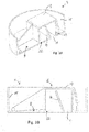
- Fig. 3A, Fig. 3B , Fig. 4A and Fig. 4B show a detailed view of the dosing cap 1, removed from the container 2, in a partially cut out view.
- Fig. 3 shows the cap in its transport position and Fig. 4 in the use position.
- Figures A show a perspective view whereas figures B show a sectional view.
- the cap member 4 has at its inside surface 8 adjacent the opening 11 some closing walls 12, 13.
- the opening 11 is provided at a position between a central point 22 of the cap member 4 and a side rim 15.
- Closing wall 12 is a lateral wall 12, whereas closing wall 13 is a closing side wall. At the opposite end of the opening 11 another closing side wall 13 is provided (not visible in this drawing).
- a dosing wall 14 is provided adjacent the opening 11 opposite with respect to the lateral closing wall 12. As can be seen in the embodiment of the present Fig. 3 and 4 , the dosing wall 14 is placed slanted, the end directing away from the inside surface 8 being placed away from the opening 11.
- the labyrinth 5 is accomplished by a box 16.
- the box 16 has a bottom 17 and walls 18, 19, 20 extending from said bottom 17. In a transport position the ends of the box walls 18, 19, 20 are positioned near the inside surface 8, whereas in a use position the said ends are positioned away from the inside surface 8, such that a chamber is obtained with an entrance 35 and an exit at opening 11.
- Box wall 19 is positioned away from dosing wall 14 so as to enable contents to reach the chamber and follow the flow path 5.
- a hinge 21 (see for example Fig. 9C hereafter) is provided. Said hinge 21 is positioned near side rim 15 opposite the opening 11 with respect to the central point 22.
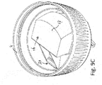
- Fig. 5A, 5B and 5C show a dosing cap not according to the present invention. No hinge construction is provided, so a very stable construction is easily obtained.
- a box shaped fixed construction 23 comprising fixed walls 24, 25, 26, 27 that extend from a fixed bottom 28 that substantially abuts the the inside surface 8 of the cap 4.
- the said walls are mutually connected to said fixed bottom 28 and surround the opening 11 at all sides thereof.
- a fixed dosing wall 29 is provided, ensuring that contents of the chamber cannot leave same unintentionally.
- the fixed dosing wall 29 is connected to the inside surface 8 of the cap 4, but it may be fixedly connected to the fixed bottom 28 optionally.
- the distance between fixed dosing wall 29 and wall 25 determines the amount of contents retained in the chamber when turning the container upside down. This distance may be changed as required.
- a control mechanism 30, also mentioned adjuster 30, is shown for maintaining the box 16 at a preset position.
- Such control mechanism 30 is part of an embodiment comprising a hinge 21 (see for example Fig. 9C hereafter) for changing the position of the box 16 as, for example, mentioned above.
- a first part of the adjuster 30 is provided, comprised of at least one recess 31.
- a mutually cooperating protruding element 32 is provided at the hingeable part, i.e. for example at the box 16.
- the protruding element 32 is received in said recess 31, such that the box 16 is retained in a substantially fixed position. Only by applying a sufficient force, the protruding element 32 is removed from the recess 31 and the box 16 can be moved to another position.
- the required force is larger than the force exerted by the contents of the container 2 acting on the box 16 when turning the container 2 upside down.
- the drawing shows only one embodiment which may be altered, for example by providing the recess 31 and protruding element 32 vice versa.
- the said recess 31 and protruding element 32 may be placed somewhere else, as long as the box 16 can be maintained at a changeable position with respect to the cap 4 or the covering plate 7 of the cap 4.
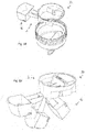
- Fig. 9A, 9B and 9C show an embodiment of the dosing cap 1 according to the invention, substantially identical to the embodiment of Fig. 3 and Fig. 4 .
- the inside surface 8 of the covering plate 7 is substantially flat, allowing a user to easy reach the box 16.
- Closing walls 12, 13, 14 are provided at the cap's inside surface 8.
- Fig. 9A shows an exploded view of the cap 4 and the box 16
- Fig. 9B shows the merged components in a transport position
- Fig. 9C shows the merged components in a use position.
- Fig. 10A, 10B and 10C show an embodiment of the dosing cap 1 according to the invention.
- the inside surface 8 of the cap 4 is substantially flat.
- the closing walls 12, 13, 14 are mutually provided at a first portion of a dosing element 3, whereas the box is provided at a second portion of dosing element 3.
- Fig. 10A shows an exploded view of the cap 4 and the dosing element 3 in an unfolded position (also shown in Fig. 15 )
- Fig. 10B shows the cap 4 and the dosing element 3 in a folded position (also shown in Fig. 14 )
- FIG. 10C shows the merged components in a transport position. Such position is shown in Fig. 11A and Fig. 11B as well. From the position of Fig. 10C , the box 16 may be moved upwards so as to reach a use position, as shown in Fig. 12A and Fig. 12B .
- the box 16 comprises projecting cams 33 at opposite edges, providing a gripping surface to fingers of a user, enabling same to place the box 16 in a desired position.
- Fig. 16 and Fig. 17 show an embodiment of a dosing element 3, wherein the box part 16 is rotated in clockwise direction so as to reach the folded position.
- Fig. 18 and Fig. 19 show an embodiment of a dosing element 3, wherein the box part 16 is rotated counterclockwise so as to reach the folded position.
- Fig. 10-19 show embodiments wherein the dosing element is comprised of a mutually and hingeably coupled combination of a base part 34 and a box part
- Fig. 20A and 20B show an embodiment of separate base part 34 and box part 16. Box part 16 is locked up between the cap member 4 and the base part 34, allowing a restricted motion of box 16, so as to choose between a transport position and a use position.
Landscapes
- Physics & Mathematics (AREA)
- Fluid Mechanics (AREA)
- General Physics & Mathematics (AREA)
- Engineering & Computer Science (AREA)
- Mechanical Engineering (AREA)
- Closures For Containers (AREA)
- Containers And Packaging Bodies Having A Special Means To Remove Contents (AREA)
Priority Applications (5)
| Application Number | Priority Date | Filing Date | Title |
|---|---|---|---|
| SI201630772T SI3306278T1 (sl) | 2016-10-06 | 2016-10-06 | Dozirni pokrov za vsebnik, dozirni element za dozirni pokrov in vsebnik z dozirnim pokrovom |
| EP16192633.2A EP3306278B1 (en) | 2016-10-06 | 2016-10-06 | A dosing cap for a container, a dosing element for the dosing cap and a container with the dosing cap |
| PL16192633T PL3306278T3 (pl) | 2016-10-06 | 2016-10-06 | Pokrywka dozująca do pojemnika, element dozujący do pokrywki dozującej oraz pojemnik z pokrywką dozującą |
| ES16192633T ES2794073T3 (es) | 2016-10-06 | 2016-10-06 | Capuchón de dosificación para un recipiente, un elemento de dosificación para el capuchón de dosificación y un recipiente con el capuchón de dosificación |
| HRP20200817TT HRP20200817T1 (hr) | 2016-10-06 | 2020-05-20 | Dozirni čep za spremnik, dozirni element za dozirni čep i spremnik sa dozirnim čepom |
Applications Claiming Priority (1)
| Application Number | Priority Date | Filing Date | Title |
|---|---|---|---|
| EP16192633.2A EP3306278B1 (en) | 2016-10-06 | 2016-10-06 | A dosing cap for a container, a dosing element for the dosing cap and a container with the dosing cap |
Publications (2)
| Publication Number | Publication Date |
|---|---|
| EP3306278A1 EP3306278A1 (en) | 2018-04-11 |
| EP3306278B1 true EP3306278B1 (en) | 2020-02-26 |
Family
ID=57133014
Family Applications (1)
| Application Number | Title | Priority Date | Filing Date |
|---|---|---|---|
| EP16192633.2A Active EP3306278B1 (en) | 2016-10-06 | 2016-10-06 | A dosing cap for a container, a dosing element for the dosing cap and a container with the dosing cap |
Country Status (5)
| Country | Link |
|---|---|
| EP (1) | EP3306278B1 (pl) |
| ES (1) | ES2794073T3 (pl) |
| HR (1) | HRP20200817T1 (pl) |
| PL (1) | PL3306278T3 (pl) |
| SI (1) | SI3306278T1 (pl) |
Families Citing this family (1)
| Publication number | Priority date | Publication date | Assignee | Title |
|---|---|---|---|---|
| JP7404149B2 (ja) * | 2020-04-30 | 2023-12-25 | 株式会社吉野工業所 | 振出しキャップ |
Family Cites Families (4)
| Publication number | Priority date | Publication date | Assignee | Title |
|---|---|---|---|---|
| US4151934A (en) * | 1976-11-02 | 1979-05-01 | Noriyoshi Saeki | Fixed volume discharge device |
| FR2382681A1 (fr) * | 1977-03-02 | 1978-09-29 | Guattari Jean | Dispositif doseur-verseur |
| DE19507402C2 (de) * | 1995-03-03 | 1997-03-20 | Henkel Kgaa | Verpackung für schüttfähige Güter |
| WO2003076304A1 (en) * | 2002-03-13 | 2003-09-18 | Nielsen Textil A/S | Dispensing device |
-
2016
- 2016-10-06 ES ES16192633T patent/ES2794073T3/es active Active
- 2016-10-06 EP EP16192633.2A patent/EP3306278B1/en active Active
- 2016-10-06 PL PL16192633T patent/PL3306278T3/pl unknown
- 2016-10-06 SI SI201630772T patent/SI3306278T1/sl unknown
-
2020
- 2020-05-20 HR HRP20200817TT patent/HRP20200817T1/hr unknown
Non-Patent Citations (1)
| Title |
|---|
| None * |
Also Published As
| Publication number | Publication date |
|---|---|
| ES2794073T3 (es) | 2020-11-17 |
| EP3306278A1 (en) | 2018-04-11 |
| HRP20200817T1 (hr) | 2020-10-02 |
| SI3306278T1 (sl) | 2020-11-30 |
| PL3306278T3 (pl) | 2020-07-27 |
Similar Documents
| Publication | Publication Date | Title |
|---|---|---|
| US7530478B2 (en) | Closure with one or more lids | |
| ES2703281T3 (es) | Cierre de dispensación | |
| HRP980177A2 (en) | Dispensing seal | |
| EP3131823B1 (en) | Container for delivering a prefixed number of products at a time and a process for making of said container | |
| EP2474482B1 (en) | Container with improved opening system | |
| ES2346527T3 (es) | Tapa de cja universal. | |
| US7445169B2 (en) | Product dispensing cap with pivotal directional spout | |
| US20070007310A1 (en) | Dispenser | |
| US20210030177A1 (en) | Utensil having self-storage handle | |
| EP3306278A1 (en) | A dosing cap for a container, a dosing element for the dosing cap and a container with the dosing cap | |
| US11634249B2 (en) | Slide-open dispenser package for loose articles | |
| KR101688623B1 (ko) | 튜브형 화장품 용기 | |
| KR101680474B1 (ko) | 유출 분출구 및 스푼을 가지는 용기 커버 | |
| EP3781001B1 (en) | Dispensing and mixing device | |
| EP1883331A1 (de) | Spendebehälter für fliessfähiges gut | |
| US1836561A (en) | Closure for containers | |
| US20160060018A1 (en) | Flexible dispensing package, in particular for fine food products and/or pharmaceutical products | |
| US9829362B2 (en) | Container and spout with open-position locking feature | |
| US11697529B2 (en) | Flow gate pour closure | |
| US20150096992A1 (en) | Sliding cap and tube | |
| KR20200044471A (ko) | 과자용기 | |
| KR102150786B1 (ko) | 용기 내의 액체의 배출량 조절이 가능한 캡 | |
| EP3489166B1 (en) | Dispenser for dry foodstuff | |
| KR20180048359A (ko) | 통과 장치 및 내용물 이동 기구 | |
| US20170001754A1 (en) | Container, A Device For Delivering A Material Capable Of Flowing, As Well As A Computer-readable Medium |
Legal Events
| Date | Code | Title | Description |
|---|---|---|---|
| PUAI | Public reference made under article 153(3) epc to a published international application that has entered the european phase |
Free format text: ORIGINAL CODE: 0009012 |
|
| STAA | Information on the status of an ep patent application or granted ep patent |
Free format text: STATUS: THE APPLICATION HAS BEEN PUBLISHED |
|
| AK | Designated contracting states |
Kind code of ref document: A1 Designated state(s): AL AT BE BG CH CY CZ DE DK EE ES FI FR GB GR HR HU IE IS IT LI LT LU LV MC MK MT NL NO PL PT RO RS SE SI SK SM TR |
|
| AX | Request for extension of the european patent |
Extension state: BA ME |
|
| STAA | Information on the status of an ep patent application or granted ep patent |
Free format text: STATUS: REQUEST FOR EXAMINATION WAS MADE |
|
| 17P | Request for examination filed |
Effective date: 20181010 |
|
| RBV | Designated contracting states (corrected) |
Designated state(s): AL AT BE BG CH CY CZ DE DK EE ES FI FR GB GR HR HU IE IS IT LI LT LU LV MC MK MT NL NO PL PT RO RS SE SI SK SM TR |
|
| STAA | Information on the status of an ep patent application or granted ep patent |
Free format text: STATUS: EXAMINATION IS IN PROGRESS |
|
| 17Q | First examination report despatched |
Effective date: 20181206 |
|
| RIC1 | Information provided on ipc code assigned before grant |
Ipc: G01F 11/26 20060101AFI20190704BHEP Ipc: G01F 11/00 20060101ALI20190704BHEP Ipc: B65D 51/24 20060101ALI20190704BHEP |
|
| GRAP | Despatch of communication of intention to grant a patent |
Free format text: ORIGINAL CODE: EPIDOSNIGR1 |
|
| STAA | Information on the status of an ep patent application or granted ep patent |
Free format text: STATUS: GRANT OF PATENT IS INTENDED |
|
| INTG | Intention to grant announced |
Effective date: 20191007 |
|
| GRAS | Grant fee paid |
Free format text: ORIGINAL CODE: EPIDOSNIGR3 |
|
| GRAA | (expected) grant |
Free format text: ORIGINAL CODE: 0009210 |
|
| STAA | Information on the status of an ep patent application or granted ep patent |
Free format text: STATUS: THE PATENT HAS BEEN GRANTED |
|
| AK | Designated contracting states |
Kind code of ref document: B1 Designated state(s): AL AT BE BG CH CY CZ DE DK EE ES FI FR GB GR HR HU IE IS IT LI LT LU LV MC MK MT NL NO PL PT RO RS SE SI SK SM TR |
|
| REG | Reference to a national code |
Ref country code: GB Ref legal event code: FG4D |
|
| REG | Reference to a national code |
Ref country code: CH Ref legal event code: EP |
|
| REG | Reference to a national code |
Ref country code: AT Ref legal event code: REF Ref document number: 1238202 Country of ref document: AT Kind code of ref document: T Effective date: 20200315 |
|
| REG | Reference to a national code |
Ref country code: IE Ref legal event code: FG4D |
|
| REG | Reference to a national code |
Ref country code: DE Ref legal event code: R096 Ref document number: 602016030458 Country of ref document: DE |
|
| REG | Reference to a national code |
Ref country code: HR Ref legal event code: TUEP Ref document number: P20200817T Country of ref document: HR |
|
| REG | Reference to a national code |
Ref country code: CH Ref legal event code: NV Representative=s name: INDUSTRIAL PROPERTY SERVICES GMBH, CH |
|
| REG | Reference to a national code |
Ref country code: NL Ref legal event code: FP |
|
| PG25 | Lapsed in a contracting state [announced via postgrant information from national office to epo] |
Ref country code: FI Free format text: LAPSE BECAUSE OF FAILURE TO SUBMIT A TRANSLATION OF THE DESCRIPTION OR TO PAY THE FEE WITHIN THE PRESCRIBED TIME-LIMIT Effective date: 20200226 Ref country code: NO Free format text: LAPSE BECAUSE OF FAILURE TO SUBMIT A TRANSLATION OF THE DESCRIPTION OR TO PAY THE FEE WITHIN THE PRESCRIBED TIME-LIMIT Effective date: 20200526 Ref country code: RS Free format text: LAPSE BECAUSE OF FAILURE TO SUBMIT A TRANSLATION OF THE DESCRIPTION OR TO PAY THE FEE WITHIN THE PRESCRIBED TIME-LIMIT Effective date: 20200226 |
|
| REG | Reference to a national code |
Ref country code: LT Ref legal event code: MG4D |
|
| PG25 | Lapsed in a contracting state [announced via postgrant information from national office to epo] |
Ref country code: IS Free format text: LAPSE BECAUSE OF FAILURE TO SUBMIT A TRANSLATION OF THE DESCRIPTION OR TO PAY THE FEE WITHIN THE PRESCRIBED TIME-LIMIT Effective date: 20200626 Ref country code: GR Free format text: LAPSE BECAUSE OF FAILURE TO SUBMIT A TRANSLATION OF THE DESCRIPTION OR TO PAY THE FEE WITHIN THE PRESCRIBED TIME-LIMIT Effective date: 20200527 Ref country code: SE Free format text: LAPSE BECAUSE OF FAILURE TO SUBMIT A TRANSLATION OF THE DESCRIPTION OR TO PAY THE FEE WITHIN THE PRESCRIBED TIME-LIMIT Effective date: 20200226 Ref country code: LV Free format text: LAPSE BECAUSE OF FAILURE TO SUBMIT A TRANSLATION OF THE DESCRIPTION OR TO PAY THE FEE WITHIN THE PRESCRIBED TIME-LIMIT Effective date: 20200226 Ref country code: BG Free format text: LAPSE BECAUSE OF FAILURE TO SUBMIT A TRANSLATION OF THE DESCRIPTION OR TO PAY THE FEE WITHIN THE PRESCRIBED TIME-LIMIT Effective date: 20200526 |
|
| REG | Reference to a national code |
Ref country code: HR Ref legal event code: T1PR Ref document number: P20200817 Country of ref document: HR |
|
| PG25 | Lapsed in a contracting state [announced via postgrant information from national office to epo] |
Ref country code: EE Free format text: LAPSE BECAUSE OF FAILURE TO SUBMIT A TRANSLATION OF THE DESCRIPTION OR TO PAY THE FEE WITHIN THE PRESCRIBED TIME-LIMIT Effective date: 20200226 Ref country code: LT Free format text: LAPSE BECAUSE OF FAILURE TO SUBMIT A TRANSLATION OF THE DESCRIPTION OR TO PAY THE FEE WITHIN THE PRESCRIBED TIME-LIMIT Effective date: 20200226 Ref country code: SM Free format text: LAPSE BECAUSE OF FAILURE TO SUBMIT A TRANSLATION OF THE DESCRIPTION OR TO PAY THE FEE WITHIN THE PRESCRIBED TIME-LIMIT Effective date: 20200226 Ref country code: PT Free format text: LAPSE BECAUSE OF FAILURE TO SUBMIT A TRANSLATION OF THE DESCRIPTION OR TO PAY THE FEE WITHIN THE PRESCRIBED TIME-LIMIT Effective date: 20200719 Ref country code: DK Free format text: LAPSE BECAUSE OF FAILURE TO SUBMIT A TRANSLATION OF THE DESCRIPTION OR TO PAY THE FEE WITHIN THE PRESCRIBED TIME-LIMIT Effective date: 20200226 Ref country code: RO Free format text: LAPSE BECAUSE OF FAILURE TO SUBMIT A TRANSLATION OF THE DESCRIPTION OR TO PAY THE FEE WITHIN THE PRESCRIBED TIME-LIMIT Effective date: 20200226 Ref country code: CZ Free format text: LAPSE BECAUSE OF FAILURE TO SUBMIT A TRANSLATION OF THE DESCRIPTION OR TO PAY THE FEE WITHIN THE PRESCRIBED TIME-LIMIT Effective date: 20200226 Ref country code: SK Free format text: LAPSE BECAUSE OF FAILURE TO SUBMIT A TRANSLATION OF THE DESCRIPTION OR TO PAY THE FEE WITHIN THE PRESCRIBED TIME-LIMIT Effective date: 20200226 |
|
| REG | Reference to a national code |
Ref country code: HR Ref legal event code: ODRP Ref document number: P20200817 Country of ref document: HR Payment date: 20201006 Year of fee payment: 5 |
|
| REG | Reference to a national code |
Ref country code: AT Ref legal event code: MK05 Ref document number: 1238202 Country of ref document: AT Kind code of ref document: T Effective date: 20200226 |
|
| REG | Reference to a national code |
Ref country code: ES Ref legal event code: FG2A Ref document number: 2794073 Country of ref document: ES Kind code of ref document: T3 Effective date: 20201117 |
|
| REG | Reference to a national code |
Ref country code: DE Ref legal event code: R097 Ref document number: 602016030458 Country of ref document: DE |
|
| PGFP | Annual fee paid to national office [announced via postgrant information from national office to epo] |
Ref country code: NL Payment date: 20201005 Year of fee payment: 5 |
|
| PLBE | No opposition filed within time limit |
Free format text: ORIGINAL CODE: 0009261 |
|
| STAA | Information on the status of an ep patent application or granted ep patent |
Free format text: STATUS: NO OPPOSITION FILED WITHIN TIME LIMIT |
|
| PG25 | Lapsed in a contracting state [announced via postgrant information from national office to epo] |
Ref country code: AT Free format text: LAPSE BECAUSE OF FAILURE TO SUBMIT A TRANSLATION OF THE DESCRIPTION OR TO PAY THE FEE WITHIN THE PRESCRIBED TIME-LIMIT Effective date: 20200226 |
|
| PGFP | Annual fee paid to national office [announced via postgrant information from national office to epo] |
Ref country code: IT Payment date: 20201019 Year of fee payment: 5 Ref country code: HR Payment date: 20201006 Year of fee payment: 5 Ref country code: FR Payment date: 20201026 Year of fee payment: 5 Ref country code: ES Payment date: 20201103 Year of fee payment: 5 Ref country code: GB Payment date: 20201020 Year of fee payment: 5 Ref country code: CH Payment date: 20201007 Year of fee payment: 5 Ref country code: DE Payment date: 20201029 Year of fee payment: 5 |
|
| 26N | No opposition filed |
Effective date: 20201127 |
|
| PGFP | Annual fee paid to national office [announced via postgrant information from national office to epo] |
Ref country code: SI Payment date: 20201006 Year of fee payment: 5 Ref country code: PL Payment date: 20201006 Year of fee payment: 5 |
|
| PG25 | Lapsed in a contracting state [announced via postgrant information from national office to epo] |
Ref country code: LU Free format text: LAPSE BECAUSE OF NON-PAYMENT OF DUE FEES Effective date: 20201006 Ref country code: MC Free format text: LAPSE BECAUSE OF FAILURE TO SUBMIT A TRANSLATION OF THE DESCRIPTION OR TO PAY THE FEE WITHIN THE PRESCRIBED TIME-LIMIT Effective date: 20200226 |
|
| REG | Reference to a national code |
Ref country code: BE Ref legal event code: MM Effective date: 20201031 |
|
| PG25 | Lapsed in a contracting state [announced via postgrant information from national office to epo] |
Ref country code: BE Free format text: LAPSE BECAUSE OF NON-PAYMENT OF DUE FEES Effective date: 20201031 |
|
| PG25 | Lapsed in a contracting state [announced via postgrant information from national office to epo] |
Ref country code: IE Free format text: LAPSE BECAUSE OF NON-PAYMENT OF DUE FEES Effective date: 20201006 |
|
| REG | Reference to a national code |
Ref country code: DE Ref legal event code: R119 Ref document number: 602016030458 Country of ref document: DE |
|
| REG | Reference to a national code |
Ref country code: HR Ref legal event code: PBON Ref document number: P20200817 Country of ref document: HR Effective date: 20211006 |
|
| REG | Reference to a national code |
Ref country code: CH Ref legal event code: PL |
|
| PG25 | Lapsed in a contracting state [announced via postgrant information from national office to epo] |
Ref country code: TR Free format text: LAPSE BECAUSE OF FAILURE TO SUBMIT A TRANSLATION OF THE DESCRIPTION OR TO PAY THE FEE WITHIN THE PRESCRIBED TIME-LIMIT Effective date: 20200226 Ref country code: MT Free format text: LAPSE BECAUSE OF FAILURE TO SUBMIT A TRANSLATION OF THE DESCRIPTION OR TO PAY THE FEE WITHIN THE PRESCRIBED TIME-LIMIT Effective date: 20200226 Ref country code: CY Free format text: LAPSE BECAUSE OF FAILURE TO SUBMIT A TRANSLATION OF THE DESCRIPTION OR TO PAY THE FEE WITHIN THE PRESCRIBED TIME-LIMIT Effective date: 20200226 |
|
| REG | Reference to a national code |
Ref country code: NL Ref legal event code: MM Effective date: 20211101 |
|
| GBPC | Gb: european patent ceased through non-payment of renewal fee |
Effective date: 20211006 |
|
| PG25 | Lapsed in a contracting state [announced via postgrant information from national office to epo] |
Ref country code: MK Free format text: LAPSE BECAUSE OF FAILURE TO SUBMIT A TRANSLATION OF THE DESCRIPTION OR TO PAY THE FEE WITHIN THE PRESCRIBED TIME-LIMIT Effective date: 20200226 Ref country code: AL Free format text: LAPSE BECAUSE OF FAILURE TO SUBMIT A TRANSLATION OF THE DESCRIPTION OR TO PAY THE FEE WITHIN THE PRESCRIBED TIME-LIMIT Effective date: 20200226 |
|
| PG25 | Lapsed in a contracting state [announced via postgrant information from national office to epo] |
Ref country code: NL Free format text: LAPSE BECAUSE OF NON-PAYMENT OF DUE FEES Effective date: 20211101 Ref country code: HR Free format text: LAPSE BECAUSE OF NON-PAYMENT OF DUE FEES Effective date: 20211006 Ref country code: GB Free format text: LAPSE BECAUSE OF NON-PAYMENT OF DUE FEES Effective date: 20211006 Ref country code: DE Free format text: LAPSE BECAUSE OF NON-PAYMENT OF DUE FEES Effective date: 20220503 |
|
| PG25 | Lapsed in a contracting state [announced via postgrant information from national office to epo] |
Ref country code: SI Free format text: LAPSE BECAUSE OF NON-PAYMENT OF DUE FEES Effective date: 20211007 Ref country code: LI Free format text: LAPSE BECAUSE OF NON-PAYMENT OF DUE FEES Effective date: 20211031 Ref country code: CH Free format text: LAPSE BECAUSE OF NON-PAYMENT OF DUE FEES Effective date: 20211031 |
|
| PG25 | Lapsed in a contracting state [announced via postgrant information from national office to epo] |
Ref country code: FR Free format text: LAPSE BECAUSE OF NON-PAYMENT OF DUE FEES Effective date: 20211031 |
|
| PG25 | Lapsed in a contracting state [announced via postgrant information from national office to epo] |
Ref country code: IT Free format text: LAPSE BECAUSE OF NON-PAYMENT OF DUE FEES Effective date: 20211006 |
|
| PG25 | Lapsed in a contracting state [announced via postgrant information from national office to epo] |
Ref country code: PL Free format text: LAPSE BECAUSE OF NON-PAYMENT OF DUE FEES Effective date: 20211006 |
|
| PG25 | Lapsed in a contracting state [announced via postgrant information from national office to epo] |
Ref country code: ES Free format text: LAPSE BECAUSE OF NON-PAYMENT OF DUE FEES Effective date: 20211007 |