EP3306179A1 - Lighting device and vehicle lamp including same - Google Patents
Lighting device and vehicle lamp including same Download PDFInfo
- Publication number
- EP3306179A1 EP3306179A1 EP16800348.1A EP16800348A EP3306179A1 EP 3306179 A1 EP3306179 A1 EP 3306179A1 EP 16800348 A EP16800348 A EP 16800348A EP 3306179 A1 EP3306179 A1 EP 3306179A1
- Authority
- EP
- European Patent Office
- Prior art keywords
- light
- lighting device
- guide member
- light guide
- circuit board
- Prior art date
- Legal status (The legal status is an assumption and is not a legal conclusion. Google has not performed a legal analysis and makes no representation as to the accuracy of the status listed.)
- Granted
Links
Images

Classifications
-
- F—MECHANICAL ENGINEERING; LIGHTING; HEATING; WEAPONS; BLASTING
- F21—LIGHTING
- F21S—NON-PORTABLE LIGHTING DEVICES; SYSTEMS THEREOF; VEHICLE LIGHTING DEVICES SPECIALLY ADAPTED FOR VEHICLE EXTERIORS
- F21S41/00—Illuminating devices specially adapted for vehicle exteriors, e.g. headlamps
- F21S41/20—Illuminating devices specially adapted for vehicle exteriors, e.g. headlamps characterised by refractors, transparent cover plates, light guides or filters
- F21S41/24—Light guides
-
- F—MECHANICAL ENGINEERING; LIGHTING; HEATING; WEAPONS; BLASTING
- F21—LIGHTING
- F21K—NON-ELECTRIC LIGHT SOURCES USING LUMINESCENCE; LIGHT SOURCES USING ELECTROCHEMILUMINESCENCE; LIGHT SOURCES USING CHARGES OF COMBUSTIBLE MATERIAL; LIGHT SOURCES USING SEMICONDUCTOR DEVICES AS LIGHT-GENERATING ELEMENTS; LIGHT SOURCES NOT OTHERWISE PROVIDED FOR
- F21K9/00—Light sources using semiconductor devices as light-generating elements, e.g. using light-emitting diodes [LED] or lasers
- F21K9/60—Optical arrangements integrated in the light source, e.g. for improving the colour rendering index or the light extraction
- F21K9/61—Optical arrangements integrated in the light source, e.g. for improving the colour rendering index or the light extraction using light guides
-
- F—MECHANICAL ENGINEERING; LIGHTING; HEATING; WEAPONS; BLASTING
- F21—LIGHTING
- F21S—NON-PORTABLE LIGHTING DEVICES; SYSTEMS THEREOF; VEHICLE LIGHTING DEVICES SPECIALLY ADAPTED FOR VEHICLE EXTERIORS
- F21S2/00—Systems of lighting devices, not provided for in main groups F21S4/00 - F21S10/00 or F21S19/00, e.g. of modular construction
-
- F—MECHANICAL ENGINEERING; LIGHTING; HEATING; WEAPONS; BLASTING
- F21—LIGHTING
- F21S—NON-PORTABLE LIGHTING DEVICES; SYSTEMS THEREOF; VEHICLE LIGHTING DEVICES SPECIALLY ADAPTED FOR VEHICLE EXTERIORS
- F21S2/00—Systems of lighting devices, not provided for in main groups F21S4/00 - F21S10/00 or F21S19/00, e.g. of modular construction
- F21S2/005—Systems of lighting devices, not provided for in main groups F21S4/00 - F21S10/00 or F21S19/00, e.g. of modular construction of modular construction
-
- F—MECHANICAL ENGINEERING; LIGHTING; HEATING; WEAPONS; BLASTING
- F21—LIGHTING
- F21S—NON-PORTABLE LIGHTING DEVICES; SYSTEMS THEREOF; VEHICLE LIGHTING DEVICES SPECIALLY ADAPTED FOR VEHICLE EXTERIORS
- F21S41/00—Illuminating devices specially adapted for vehicle exteriors, e.g. headlamps
- F21S41/10—Illuminating devices specially adapted for vehicle exteriors, e.g. headlamps characterised by the light source
- F21S41/19—Attachment of light sources or lamp holders
-
- F—MECHANICAL ENGINEERING; LIGHTING; HEATING; WEAPONS; BLASTING
- F21—LIGHTING
- F21S—NON-PORTABLE LIGHTING DEVICES; SYSTEMS THEREOF; VEHICLE LIGHTING DEVICES SPECIALLY ADAPTED FOR VEHICLE EXTERIORS
- F21S41/00—Illuminating devices specially adapted for vehicle exteriors, e.g. headlamps
- F21S41/30—Illuminating devices specially adapted for vehicle exteriors, e.g. headlamps characterised by reflectors
- F21S41/32—Optical layout thereof
-
- F—MECHANICAL ENGINEERING; LIGHTING; HEATING; WEAPONS; BLASTING
- F21—LIGHTING
- F21S—NON-PORTABLE LIGHTING DEVICES; SYSTEMS THEREOF; VEHICLE LIGHTING DEVICES SPECIALLY ADAPTED FOR VEHICLE EXTERIORS
- F21S41/00—Illuminating devices specially adapted for vehicle exteriors, e.g. headlamps
- F21S41/40—Illuminating devices specially adapted for vehicle exteriors, e.g. headlamps characterised by screens, non-reflecting members, light-shielding members or fixed shades
-
- F—MECHANICAL ENGINEERING; LIGHTING; HEATING; WEAPONS; BLASTING
- F21—LIGHTING
- F21S—NON-PORTABLE LIGHTING DEVICES; SYSTEMS THEREOF; VEHICLE LIGHTING DEVICES SPECIALLY ADAPTED FOR VEHICLE EXTERIORS
- F21S43/00—Signalling devices specially adapted for vehicle exteriors, e.g. brake lamps, direction indicator lights or reversing lights
- F21S43/10—Signalling devices specially adapted for vehicle exteriors, e.g. brake lamps, direction indicator lights or reversing lights characterised by the light source
- F21S43/13—Signalling devices specially adapted for vehicle exteriors, e.g. brake lamps, direction indicator lights or reversing lights characterised by the light source characterised by the type of light source
- F21S43/14—Light emitting diodes [LED]
- F21S43/145—Surface emitters, e.g. organic light emitting diodes [OLED]
-
- F—MECHANICAL ENGINEERING; LIGHTING; HEATING; WEAPONS; BLASTING
- F21—LIGHTING
- F21S—NON-PORTABLE LIGHTING DEVICES; SYSTEMS THEREOF; VEHICLE LIGHTING DEVICES SPECIALLY ADAPTED FOR VEHICLE EXTERIORS
- F21S43/00—Signalling devices specially adapted for vehicle exteriors, e.g. brake lamps, direction indicator lights or reversing lights
- F21S43/10—Signalling devices specially adapted for vehicle exteriors, e.g. brake lamps, direction indicator lights or reversing lights characterised by the light source
- F21S43/19—Attachment of light sources or lamp holders
-
- F—MECHANICAL ENGINEERING; LIGHTING; HEATING; WEAPONS; BLASTING
- F21—LIGHTING
- F21S—NON-PORTABLE LIGHTING DEVICES; SYSTEMS THEREOF; VEHICLE LIGHTING DEVICES SPECIALLY ADAPTED FOR VEHICLE EXTERIORS
- F21S43/00—Signalling devices specially adapted for vehicle exteriors, e.g. brake lamps, direction indicator lights or reversing lights
- F21S43/20—Signalling devices specially adapted for vehicle exteriors, e.g. brake lamps, direction indicator lights or reversing lights characterised by refractors, transparent cover plates, light guides or filters
- F21S43/235—Light guides
- F21S43/236—Light guides characterised by the shape of the light guide
- F21S43/237—Light guides characterised by the shape of the light guide rod-shaped
-
- F—MECHANICAL ENGINEERING; LIGHTING; HEATING; WEAPONS; BLASTING
- F21—LIGHTING
- F21S—NON-PORTABLE LIGHTING DEVICES; SYSTEMS THEREOF; VEHICLE LIGHTING DEVICES SPECIALLY ADAPTED FOR VEHICLE EXTERIORS
- F21S43/00—Signalling devices specially adapted for vehicle exteriors, e.g. brake lamps, direction indicator lights or reversing lights
- F21S43/20—Signalling devices specially adapted for vehicle exteriors, e.g. brake lamps, direction indicator lights or reversing lights characterised by refractors, transparent cover plates, light guides or filters
- F21S43/235—Light guides
- F21S43/236—Light guides characterised by the shape of the light guide
- F21S43/239—Light guides characterised by the shape of the light guide plate-shaped
-
- F—MECHANICAL ENGINEERING; LIGHTING; HEATING; WEAPONS; BLASTING
- F21—LIGHTING
- F21S—NON-PORTABLE LIGHTING DEVICES; SYSTEMS THEREOF; VEHICLE LIGHTING DEVICES SPECIALLY ADAPTED FOR VEHICLE EXTERIORS
- F21S43/00—Signalling devices specially adapted for vehicle exteriors, e.g. brake lamps, direction indicator lights or reversing lights
- F21S43/20—Signalling devices specially adapted for vehicle exteriors, e.g. brake lamps, direction indicator lights or reversing lights characterised by refractors, transparent cover plates, light guides or filters
- F21S43/235—Light guides
- F21S43/242—Light guides characterised by the emission area
- F21S43/245—Light guides characterised by the emission area emitting light from one or more of its major surfaces
-
- F—MECHANICAL ENGINEERING; LIGHTING; HEATING; WEAPONS; BLASTING
- F21—LIGHTING
- F21S—NON-PORTABLE LIGHTING DEVICES; SYSTEMS THEREOF; VEHICLE LIGHTING DEVICES SPECIALLY ADAPTED FOR VEHICLE EXTERIORS
- F21S43/00—Signalling devices specially adapted for vehicle exteriors, e.g. brake lamps, direction indicator lights or reversing lights
- F21S43/20—Signalling devices specially adapted for vehicle exteriors, e.g. brake lamps, direction indicator lights or reversing lights characterised by refractors, transparent cover plates, light guides or filters
- F21S43/26—Refractors, transparent cover plates, light guides or filters not provided in groups F21S43/235 - F21S43/255
-
- F—MECHANICAL ENGINEERING; LIGHTING; HEATING; WEAPONS; BLASTING
- F21—LIGHTING
- F21S—NON-PORTABLE LIGHTING DEVICES; SYSTEMS THEREOF; VEHICLE LIGHTING DEVICES SPECIALLY ADAPTED FOR VEHICLE EXTERIORS
- F21S43/00—Signalling devices specially adapted for vehicle exteriors, e.g. brake lamps, direction indicator lights or reversing lights
- F21S43/30—Signalling devices specially adapted for vehicle exteriors, e.g. brake lamps, direction indicator lights or reversing lights characterised by reflectors
- F21S43/31—Optical layout thereof
-
- F—MECHANICAL ENGINEERING; LIGHTING; HEATING; WEAPONS; BLASTING
- F21—LIGHTING
- F21S—NON-PORTABLE LIGHTING DEVICES; SYSTEMS THEREOF; VEHICLE LIGHTING DEVICES SPECIALLY ADAPTED FOR VEHICLE EXTERIORS
- F21S43/00—Signalling devices specially adapted for vehicle exteriors, e.g. brake lamps, direction indicator lights or reversing lights
- F21S43/40—Signalling devices specially adapted for vehicle exteriors, e.g. brake lamps, direction indicator lights or reversing lights characterised by the combination of reflectors and refractors
-
- F—MECHANICAL ENGINEERING; LIGHTING; HEATING; WEAPONS; BLASTING
- F21—LIGHTING
- F21V—FUNCTIONAL FEATURES OR DETAILS OF LIGHTING DEVICES OR SYSTEMS THEREOF; STRUCTURAL COMBINATIONS OF LIGHTING DEVICES WITH OTHER ARTICLES, NOT OTHERWISE PROVIDED FOR
- F21V7/00—Reflectors for light sources
-
- G—PHYSICS
- G02—OPTICS
- G02B—OPTICAL ELEMENTS, SYSTEMS OR APPARATUS
- G02B6/00—Light guides; Structural details of arrangements comprising light guides and other optical elements, e.g. couplings
- G02B6/0001—Light guides; Structural details of arrangements comprising light guides and other optical elements, e.g. couplings specially adapted for lighting devices or systems
-
- G—PHYSICS
- G02—OPTICS
- G02B—OPTICAL ELEMENTS, SYSTEMS OR APPARATUS
- G02B6/00—Light guides; Structural details of arrangements comprising light guides and other optical elements, e.g. couplings
- G02B6/0001—Light guides; Structural details of arrangements comprising light guides and other optical elements, e.g. couplings specially adapted for lighting devices or systems
- G02B6/0011—Light guides; Structural details of arrangements comprising light guides and other optical elements, e.g. couplings specially adapted for lighting devices or systems the light guides being planar or of plate-like form
- G02B6/0013—Means for improving the coupling-in of light from the light source into the light guide
- G02B6/0015—Means for improving the coupling-in of light from the light source into the light guide provided on the surface of the light guide or in the bulk of it
- G02B6/002—Means for improving the coupling-in of light from the light source into the light guide provided on the surface of the light guide or in the bulk of it by shaping at least a portion of the light guide, e.g. with collimating, focussing or diverging surfaces
- G02B6/0021—Means for improving the coupling-in of light from the light source into the light guide provided on the surface of the light guide or in the bulk of it by shaping at least a portion of the light guide, e.g. with collimating, focussing or diverging surfaces for housing at least a part of the light source, e.g. by forming holes or recesses
-
- H—ELECTRICITY
- H05—ELECTRIC TECHNIQUES NOT OTHERWISE PROVIDED FOR
- H05K—PRINTED CIRCUITS; CASINGS OR CONSTRUCTIONAL DETAILS OF ELECTRIC APPARATUS; MANUFACTURE OF ASSEMBLAGES OF ELECTRICAL COMPONENTS
- H05K1/00—Printed circuits
- H05K1/02—Details
- H05K1/0274—Optical details, e.g. printed circuits comprising integral optical means
-
- F—MECHANICAL ENGINEERING; LIGHTING; HEATING; WEAPONS; BLASTING
- F21—LIGHTING
- F21S—NON-PORTABLE LIGHTING DEVICES; SYSTEMS THEREOF; VEHICLE LIGHTING DEVICES SPECIALLY ADAPTED FOR VEHICLE EXTERIORS
- F21S41/00—Illuminating devices specially adapted for vehicle exteriors, e.g. headlamps
- F21S41/30—Illuminating devices specially adapted for vehicle exteriors, e.g. headlamps characterised by reflectors
- F21S41/37—Illuminating devices specially adapted for vehicle exteriors, e.g. headlamps characterised by reflectors characterised by their material, surface treatment or coatings
-
- F—MECHANICAL ENGINEERING; LIGHTING; HEATING; WEAPONS; BLASTING
- F21—LIGHTING
- F21S—NON-PORTABLE LIGHTING DEVICES; SYSTEMS THEREOF; VEHICLE LIGHTING DEVICES SPECIALLY ADAPTED FOR VEHICLE EXTERIORS
- F21S43/00—Signalling devices specially adapted for vehicle exteriors, e.g. brake lamps, direction indicator lights or reversing lights
- F21S43/20—Signalling devices specially adapted for vehicle exteriors, e.g. brake lamps, direction indicator lights or reversing lights characterised by refractors, transparent cover plates, light guides or filters
- F21S43/281—Materials thereof; Structures thereof; Properties thereof; Coatings thereof
- F21S43/28135—Structures encapsulating the light source
-
- F—MECHANICAL ENGINEERING; LIGHTING; HEATING; WEAPONS; BLASTING
- F21—LIGHTING
- F21S—NON-PORTABLE LIGHTING DEVICES; SYSTEMS THEREOF; VEHICLE LIGHTING DEVICES SPECIALLY ADAPTED FOR VEHICLE EXTERIORS
- F21S43/00—Signalling devices specially adapted for vehicle exteriors, e.g. brake lamps, direction indicator lights or reversing lights
- F21S43/30—Signalling devices specially adapted for vehicle exteriors, e.g. brake lamps, direction indicator lights or reversing lights characterised by reflectors
- F21S43/33—Signalling devices specially adapted for vehicle exteriors, e.g. brake lamps, direction indicator lights or reversing lights characterised by reflectors characterised by their material, surface treatment or coatings
-
- F—MECHANICAL ENGINEERING; LIGHTING; HEATING; WEAPONS; BLASTING
- F21—LIGHTING
- F21Y—INDEXING SCHEME ASSOCIATED WITH SUBCLASSES F21K, F21L, F21S and F21V, RELATING TO THE FORM OR THE KIND OF THE LIGHT SOURCES OR OF THE COLOUR OF THE LIGHT EMITTED
- F21Y2101/00—Point-like light sources
-
- F—MECHANICAL ENGINEERING; LIGHTING; HEATING; WEAPONS; BLASTING
- F21—LIGHTING
- F21Y—INDEXING SCHEME ASSOCIATED WITH SUBCLASSES F21K, F21L, F21S and F21V, RELATING TO THE FORM OR THE KIND OF THE LIGHT SOURCES OR OF THE COLOUR OF THE LIGHT EMITTED
- F21Y2115/00—Light-generating elements of semiconductor light sources
- F21Y2115/10—Light-emitting diodes [LED]
-
- G—PHYSICS
- G02—OPTICS
- G02B—OPTICAL ELEMENTS, SYSTEMS OR APPARATUS
- G02B6/00—Light guides; Structural details of arrangements comprising light guides and other optical elements, e.g. couplings
- G02B6/0001—Light guides; Structural details of arrangements comprising light guides and other optical elements, e.g. couplings specially adapted for lighting devices or systems
- G02B6/0011—Light guides; Structural details of arrangements comprising light guides and other optical elements, e.g. couplings specially adapted for lighting devices or systems the light guides being planar or of plate-like form
- G02B6/0033—Means for improving the coupling-out of light from the light guide
- G02B6/0035—Means for improving the coupling-out of light from the light guide provided on the surface of the light guide or in the bulk of it
- G02B6/004—Scattering dots or dot-like elements, e.g. microbeads, scattering particles, nanoparticles
- G02B6/0041—Scattering dots or dot-like elements, e.g. microbeads, scattering particles, nanoparticles provided in the bulk of the light guide
-
- G—PHYSICS
- G02—OPTICS
- G02B—OPTICAL ELEMENTS, SYSTEMS OR APPARATUS
- G02B6/00—Light guides; Structural details of arrangements comprising light guides and other optical elements, e.g. couplings
- G02B6/0001—Light guides; Structural details of arrangements comprising light guides and other optical elements, e.g. couplings specially adapted for lighting devices or systems
- G02B6/0011—Light guides; Structural details of arrangements comprising light guides and other optical elements, e.g. couplings specially adapted for lighting devices or systems the light guides being planar or of plate-like form
- G02B6/0065—Manufacturing aspects; Material aspects
-
- G—PHYSICS
- G02—OPTICS
- G02B—OPTICAL ELEMENTS, SYSTEMS OR APPARATUS
- G02B6/00—Light guides; Structural details of arrangements comprising light guides and other optical elements, e.g. couplings
- G02B6/0001—Light guides; Structural details of arrangements comprising light guides and other optical elements, e.g. couplings specially adapted for lighting devices or systems
- G02B6/0011—Light guides; Structural details of arrangements comprising light guides and other optical elements, e.g. couplings specially adapted for lighting devices or systems the light guides being planar or of plate-like form
- G02B6/0066—Light guides; Structural details of arrangements comprising light guides and other optical elements, e.g. couplings specially adapted for lighting devices or systems the light guides being planar or of plate-like form characterised by the light source being coupled to the light guide
- G02B6/0073—Light emitting diode [LED]
-
- G—PHYSICS
- G02—OPTICS
- G02B—OPTICAL ELEMENTS, SYSTEMS OR APPARATUS
- G02B6/00—Light guides; Structural details of arrangements comprising light guides and other optical elements, e.g. couplings
- G02B6/0001—Light guides; Structural details of arrangements comprising light guides and other optical elements, e.g. couplings specially adapted for lighting devices or systems
- G02B6/0011—Light guides; Structural details of arrangements comprising light guides and other optical elements, e.g. couplings specially adapted for lighting devices or systems the light guides being planar or of plate-like form
- G02B6/0081—Mechanical or electrical aspects of the light guide and light source in the lighting device peculiar to the adaptation to planar light guides, e.g. concerning packaging
- G02B6/0083—Details of electrical connections of light sources to drivers, circuit boards, or the like
-
- H—ELECTRICITY
- H05—ELECTRIC TECHNIQUES NOT OTHERWISE PROVIDED FOR
- H05K—PRINTED CIRCUITS; CASINGS OR CONSTRUCTIONAL DETAILS OF ELECTRIC APPARATUS; MANUFACTURE OF ASSEMBLAGES OF ELECTRICAL COMPONENTS
- H05K1/00—Printed circuits
- H05K1/18—Printed circuits structurally associated with non-printed electric components
- H05K1/189—Printed circuits structurally associated with non-printed electric components characterised by the use of flexible or folded printed circuits
-
- H—ELECTRICITY
- H05—ELECTRIC TECHNIQUES NOT OTHERWISE PROVIDED FOR
- H05K—PRINTED CIRCUITS; CASINGS OR CONSTRUCTIONAL DETAILS OF ELECTRIC APPARATUS; MANUFACTURE OF ASSEMBLAGES OF ELECTRICAL COMPONENTS
- H05K2201/00—Indexing scheme relating to printed circuits covered by H05K1/00
- H05K2201/01—Dielectrics
- H05K2201/0104—Properties and characteristics in general
- H05K2201/0108—Transparent
-
- H—ELECTRICITY
- H05—ELECTRIC TECHNIQUES NOT OTHERWISE PROVIDED FOR
- H05K—PRINTED CIRCUITS; CASINGS OR CONSTRUCTIONAL DETAILS OF ELECTRIC APPARATUS; MANUFACTURE OF ASSEMBLAGES OF ELECTRICAL COMPONENTS
- H05K2201/00—Indexing scheme relating to printed circuits covered by H05K1/00
- H05K2201/10—Details of components or other objects attached to or integrated in a printed circuit board
- H05K2201/10007—Types of components
- H05K2201/10106—Light emitting diode [LED]
Definitions
- Embodiments of the present invention relate to a lighting device structure that can increase the degree of freedom of a light emitting surface and realize an effect of changing the shape and a three-dimensional effect of a light.
- the lighting unit can be applied variously to a backlight unit applied to a flat plate display, an interior lamp used in an indoor environment, a headlight, a fog light, a retraction light, a car-width light, a number light, a tail light, a brake light, turn signal light, emergency flashing light which are installed outside a vehicle, an indoor lighting installed inside a vehicle, or the like.
- Most of these lighting are mostly approaches in terms of brightness of a surface light source by applying a member such as a light guide plate that efficiently transmits light.
- the present invention can provide a lighting device that does not limit a light exit surface to one direction but can realize lighting in a structure in which light is emitted in both directions, and thus the degree of freedom of design according to the direction of light emitting can be increased.
- a lighting device in which a light image can be realized as three-dimensional light having a depth feeling and a volume feeling in a bidirectional light emitting structure.
- a lighting device including: a light guide layer in which light exit surfaces are formed on one surface and on the other surface opposite to the one surface; a light emitting module that is embedded in the light guide layer and disposed at an outer periphery of a light exit surface of the light guide layer; and a light-transmitting printed circuit board that mounts an light emitting device on the light emitting module and is disposed under the light guide layer.
- a lighting device which can increase the degree of freedom of design according to a light exit direction by implementing the lighting having a structure in which light is exited in both directions without limiting the light exit surface to one direction.
- an effect is realized which changes shapes and a three-dimensional effect of light according to viewing angles by providing the optical member having a protruding optical pattern at a position corresponding to the light exit surface of the light guide member having the bidirectional light exit surface, and thus there is an effect that can provide a lighting device with improved aesthetics and an advantage that can be applied to various types of lighting device.
- the exit light exited from the light emitting module can be realized as three-dimensional light and the image of the surface light source can be realized, a separate external lens structure can be removed, thereby simplifying the structure of the lighting device.
- the embodiment of the present invention it is possible to control the length, thickness, and shape of the light that can be realized so that the three-dimensional feeling of the light itself can be sensed and at the same time, the flexibility of the device itself can be ensured, the device can be efficiently installed in various equipment or locations by guiding light by using a resin layer as a member for guiding light in a structure, and there are effects that the light efficiency can be increased, the number of light emitting units can be reduced, and the overall thickness of the lighting device can be reduced.
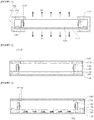
- Fig. 1 is a conceptual cross-sectional view illustrating main portions of a lighting device according to an embodiment of the present invention.
- the lighting device includes a light guide member 130 which has light exit surfaces x1 and x2 on a surface and the other surface facing the surface, a light emitting module 120 which is embedded in the light guide member 130 and disposed at an outer periphery of a light exit surface of the light guide member, and a light transmitting printed circuit board 110 on which a light emitting device in the light emitting module is mounted and is disposed under the light guide member.
- the lighting device according to the embodiment of the present invention can be realized so that light can be exited from both surfaces of the light guide member and thus the degree of freedom of design in a disposition location thereof is maximized.
- the light emitting module 120 is received in a structure of beings embedded in the light guide member 130 and the light exit direction of the light emitting module 120 is directed toward an inside portion of the light guide member 130.
- the light guide member 130 can diffuse and scatter light, and the surface light emission can be realized on the light exit surfaces x1 and x2, which are both surfaces of the light guide member, respectively.
- a light-transmitting printed circuit board is disposed on the other surface of the light guide member so that both-side light emission can be realized.
- the light-transmitting printed circuit board 110 is a printed circuit board on which a conductive pattern is formed on a transparent base substrate.
- the light-transmitting printed circuit board 110 may have a light transmittance of 80% or more.
- the light intensity exiting through the light emitting surface x2 of one surface of the light guide member 130 and the light intensity exiting through the light exit surface x1 of the other surface are implemented differently. In this case, the intensity of light exited to the light exit surface x2 of one surface of the light guide member 130 can be larger than the light intensity exited through the light exit surface x1 of the other surface.
- the light emitting module 120 may include one or a plurality of light emitting devices, a structure in which one light emitting device is provided in one light emitting module as a structure which can achieve a light efficiency with minimum cost will be described as an example.
- the light emitting device mounted on the light emitting module 120 may be a solid light emitting device and can apply any one light source selected from the group consisting of LED, OLED, laser diode (LD), laser, and VCSEL, as an example. In the present invention, the light emitting device to which the LED is applied will be described.
- the light emitting device mounted on the light emitting module may be a side view type LED.
- the light emitting diode having a structure in which the light exit direction is not directly directed upward but exits toward the side can be used as a light emitting device of the present invention.
- the lighting device 100a according to the embodiment of the present invention disposes the light emitting device 120 formed of a side view type light emitting diode directly inside the light guide member, it is possible to reduce the total number of the light emitting units and to innovatively reduce the total weight and thickness of the lighting device by the light being diffused and guided in the direction of the light exit surface by utilizing the light guide member which implements the light diffusion and reflection function.
- the light-transmitting printed circuit board may apply a flexible substrate as a structure in which a conductive pattern is formed on a base substrate, and preferably uses a substrate having a light transmittance of 80% or more.
- a substrate having a light transmittance of 80% or more any one of acrylic resin, polystyrene (PS), polymethyl methacrylate (PMMA), cyclic olefin copoly (COC), polyethylene terephthalate (PET) and polyimide film (PI) can be applied as the light-transmitting printed circuit board.
- the conductive pattern may be a circuit pattern realized by patterning an Ag paste or may be a Cu pattern patterned to have a thin thickness.
- the lighting device may include a bezel portion 200 for receiving and supporting outer peripheries of the light guide member 130 and the light-transmitting printed circuit board 110 in an inside thereof.
- the bezel portion 200 may be disposed at an outer periphery of the light exit surface and a light reflection portion 210 corresponding to the upper portion of a disposition location of the light emitting device may protrude from a center portion of the light guide member.
- the light reflection portion 210 may include any one of Al, PC, PP, ABS, and PBT which are reflection materials.
- a reflection material including any one of Al, TiO 2 , CaCo 3 , BaSo 4 , Al 2 O 3 , Silicon, and PS may be coated on the inner surface of a general synthetic resin or metal material.
- the light reflection portion 210 may be formed in a structure in which an end of the light reflection portion protrudes (a2) beyond a position where the light exit surface a1 of the light emitting device is disposed. This is for the purpose of maximizing the light utilization efficiency by reflecting the path of the light exited upward from the light emitting device and guiding the light to the inside portion of the light guide member again.
- the light reflection portion can also solve the hot spot problem, which is a deterioration phenomenon, on the upper surface of the light guide member formed of a resin material, which is generated as strong emitting light on one surface of the light guide member.
- the bezel portion 200 may be formed as a structure which has a side portion 220 and a bottom portion that are bent at one end of the light reflection portion 210 and has a receiving portion which receives the outer periphery of the light-transmitting printed circuit board therein.
- Such a structure makes it possible to realize a stable lighting device structure while securing a light exit surface.
- the light guide member 130 may be preferably formed of a flexible resin material so that the light guide member 130 can be freely designed in a narrow location where a housing of a vehicle lamp or an external lighting device is required.
- a further feature of high heat resistance is required with respect to the light guide member 130. Therefore, in this embodiment, an ultraviolet curing resin or a silicone resin having high heat resistance can be applied to the light guide member 130.
- the light guide member 130 may be made of an ultraviolet curing resin including an oligomer.
- the resin layer may be formed using a resin having urethane acrylate oligomer as a main raw material.
- a resin obtained by mixing a urethane acrylate oligomer and a polyacrylic polymer type which are synthetic oligomers may be used as the resin layer.
- it may further include monomers mixed with isobornyl acrylate (IBOA), hydroxypropyl acrylate (HPA), 2-hydroxyethyl acrylate (2-HEA), or the like which are low boiling point diluent type reactive monomers, and as a photoinitiator (for example, 1-hydroxycyclohexyl phenyl-ketone or the like) or an antioxidant can be mixed therein as an additive.
- IBOA isobornyl acrylate
- HPA hydroxypropyl acrylate
- 2-HEA 2-hydroxyethyl acrylate
- an antioxidant can be mixed therein as an additive.
- Such a mixture is advantageous in that not only high heat resistance is ensure
- Fig. 2 illustrates a structure of a lighting device according to another embodiment of the present invention.
- the optical members 140 and 150 disposed on the upper portion of the light guide member 130 or the lower portion 161 of the light-transmitting printed circuit board 110 are further provided.
- the optical members 140 and 150 perform a function of increasing the degree of diffusion of the exit light emitted through the light exit surface of the light guide member and securing the light uniformity.
- the optical members 140 and 150 may be formed of an acrylic resin having a sheet or film structure, the present invention is not limited thereto.
- optical members 140 and 150 may apply any material that can perform the diffusing function such as high permeability plastics including polystyrene (PS), polymethylmethacrylate (PMMA), and cyclic olefin copoly (COC), polyethylene terephthalate (PET), resin, or the like.
- high permeability plastics including polystyrene (PS), polymethylmethacrylate (PMMA), and cyclic olefin copoly (COC), polyethylene terephthalate (PET), resin, or the like.
- a light diffusion pattern 160 implemented as a light diffusing material can be further implemented on the optical member 150 among the light exit surface of the light guide member 130 in a location where the light-transmitting printed circuit board 110 is disposed. According to this, the intensity and diffusion of the light emitted through the light-transmitting printed circuit board 110 are increased to increase the uniformity of the light.
- the light guide member 130 may further include a diffusion member 131 thereon having a particle structure in order to increase light diffusion.
- the diffusion member 131 may further include a plurality of bead structures in which a hollow (or an openig) is formed therein with mixed and diffused forms, and the diffusion member 131 serves to improve reflection and diffusion characteristics of light. For example, when the light exited from the light emitting module is incident on the diffusion member 131 in the light guide member 130, the light is reflected and transmitted through the hollow of the diffusion member 131, is diffused and condensed, and is exited to an upper portion of a light receiving layer.
- the diffusion member may be made of any one selected from the group consisting of silicon, silica, glass bubble, PMMA, urethane, Zn, Zr, Al 2 O 3 , and acryl and a particle size thereof may be formed in a range of 1 ⁇ m m to 20 ⁇ m, the present invention is not limited thereto.
- a structure can be implemented in which light diffusion resin layers 170 and 180 are in close contact with a surface of the light guide member and a surface of the light-transmitting printed circuit board in place of the optical member described above.
- the structures of the other optical guide layer, the light emitting module, and the light transmitting printed circuit board are the same as those of Fig. 1 . Since the layer which is implemented by the optical diffusion resin layers 170 and 180 can realize the diffusion effect of light and there is an advantage that the stability can be structurally ensured because the layer and the light guide member is in close contact with each other. Furthermore, since the diffusion member in Fig.
- the diffusion member 131 may be also provided in the interior of the light guide member as described above in the embodiment of Fig. 4 .
- Fig. 6 is a modification structure of the embodiment of the present invention described above referring to Fig. 2 , there is a difference in that light can have a depth feeling and a three-dimensional feeling as illustrated in Fig. 6 , such that the image formed on the light exit surface progresses in the depth direction of the light guide member.
- an optical member can be disposed in which protruding optical patterns 320 and 420 protruding in the direction of the light exit surface are implemented on the surfaces of the optical members 310 and 410 on one surface or the other surface of the light guide member 130.
- the protruding optical patterns 320 and 420 may be formed on the surface of the optical member in the direction in which the light exit surface of the light guide layer is disposed.
- the protruding optical patterns 320 and 420 may be generally formed in a line pattern of which a cross-section of pattern protrudes from the surface of the transparent substrate 410 has a polygonal structure, or may be formed by any one of a prism sheet having a plurality of unit prism lens patterns, a microlens array sheet, and a lenticular lens sheet or a combination thereof.
- the light guide member is made of a resin having flexibility and the thickness of the light guiding plate of the related art can be innovatively reduced, the thinness of the entire product can be realized and since a transparent printed circuit board is used, and the light exit surface can be implemented in both directions, there are an advantage of being easily applicable to the bent surface of the installation location, an advantage of improving the degree of freedom of design, and an advantage of being capable of being also applied to other vehicle lighting or flexible displays.
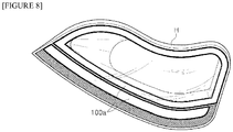
- Fig. 8 illustrates the application of the lighting device according to the embodiment of the present invention illustrated in Fig. 1 to Fig. 7 to a vehicle lamp.
- a lighting device 100a has a constant flexibility by being applied a light guide member using resin and a flexible circuit board. Further, since it is formed by implementing a double-sided light-emitting structure, the degree of freedom of design is increased. Therefore, the lighting device can be easily mounted on the headlight housing for a vehicle having the bent shape as illustrated in Fig. 8 and thus there are an effect that can improves the degree of design freedom of the finished product combined with the housing and an effect that can obtain uniform brightness and illumination despite of improving the degree of design freedom.
Landscapes
- Engineering & Computer Science (AREA)
- General Engineering & Computer Science (AREA)
- Physics & Mathematics (AREA)
- Optics & Photonics (AREA)
- Microelectronics & Electronic Packaging (AREA)
- General Physics & Mathematics (AREA)
- Planar Illumination Modules (AREA)
- Non-Portable Lighting Devices Or Systems Thereof (AREA)
- Manufacturing Of Printed Wiring (AREA)
Abstract
Description
- Embodiments of the present invention relate to a lighting device structure that can increase the degree of freedom of a light emitting surface and realize an effect of changing the shape and a three-dimensional effect of a light.
- The lighting unit can be applied variously to a backlight unit applied to a flat plate display, an interior lamp used in an indoor environment, a headlight, a fog light, a retraction light, a car-width light, a number light, a tail light, a brake light, turn signal light, emergency flashing light which are installed outside a vehicle, an indoor lighting installed inside a vehicle, or the like. Most of these lighting are mostly approaches in terms of brightness of a surface light source by applying a member such as a light guide plate that efficiently transmits light.
- In a case of vehicle lighting, LEDs, which realize high optical efficiency, recently are being developed as a light source, and the use of LED packages as a light source is becoming more frequent in a case of vehicle lighting in a form of a surface lighting. However, in a case where the LED package is used as a light source, it is inevitably necessary to increase the number of optical elements that are responsible for the light emitting surface in case of where high light quantity is required or for the surface emitting and there are many problems in implementation of circuit between elements due to a cost aspect, the problem of heat dissipation, a curved portion of the vehicle, a narrow space, or the like and thus there is a fatal drawback that leads to high cost and low efficiency. Particularly, in a case of vehicle lighting disposed on in a limited space, many various designs are required, and in recent years, there has been an increasing demand for realizing three-dimensional light (3D) in light of a specific shape.
- In addition, there is a growing need for a structure that can increase the degree of freedom of design and such attention is being extended to lighting that does not limit the light emitting surface to one direction.
- The embodiments of the present invention are devised to solve the problems described above. In particular, the present invention can provide a lighting device that does not limit a light exit surface to one direction but can realize lighting in a structure in which light is emitted in both directions, and thus the degree of freedom of design according to the direction of light emitting can be increased.
- In addition, a lighting device can be provided in which a light image can be realized as three-dimensional light having a depth feeling and a volume feeling in a bidirectional light emitting structure.
- As means of for solving the problems described above, according to an embodiment of the present invention, there is provided a lighting device including: a light guide layer in which light exit surfaces are formed on one surface and on the other surface opposite to the one surface; a light emitting module that is embedded in the light guide layer and disposed at an outer periphery of a light exit surface of the light guide layer; and a light-transmitting printed circuit board that mounts an light emitting device on the light emitting module and is disposed under the light guide layer.
- According to the embodiment of the present invention, there is an advantage that a lighting device is realized which can increase the degree of freedom of design according to a light exit direction by implementing the lighting having a structure in which light is exited in both directions without limiting the light exit surface to one direction.
- In addition, according to the embodiment of the present invention, an effect is realized which changes shapes and a three-dimensional effect of light according to viewing angles by providing the optical member having a protruding optical pattern at a position corresponding to the light exit surface of the light guide member having the bidirectional light exit surface, and thus there is an effect that can provide a lighting device with improved aesthetics and an advantage that can be applied to various types of lighting device.
- Furthermore, since the exit light exited from the light emitting module can be realized as three-dimensional light and the image of the surface light source can be realized, a separate external lens structure can be removed, thereby simplifying the structure of the lighting device.
- In addition, according to the embodiment of the present invention, it is possible to control the length, thickness, and shape of the light that can be realized so that the three-dimensional feeling of the light itself can be sensed and at the same time, the flexibility of the device itself can be ensured, the device can be efficiently installed in various equipment or locations by guiding light by using a resin layer as a member for guiding light in a structure, and there are effects that the light efficiency can be increased, the number of light emitting units can be reduced, and the overall thickness of the lighting device can be reduced.
-
-
Fig. 1 is a conceptual cross-sectional view illustrating main portions of a lighting device according to an embodiment of the present invention. -
Fig. 2 to Fig. 6 illustrate a structure of a lighting device according to another embodiment of the present invention. -
Fig. 7 illustrates a three-dimensional light image according toFig. 6 . -
Fig. 8 illustrates application of the lighting device according to the embodiments of the present invention illustrated inFig. 1 to Fig. 7 described above to a vehicle lamp. - Hereinafter, the configuration and operation according to the present invention will be described in detail referring to the accompanying drawings. In the following description referring to the accompanying drawings, the same reference numerals denote the same components regardless of the reference numerals and a duplicate description thereof will be omitted. Although the terms first, second, or the like may be used to describe various constituent elements, the constituent elements should not be limited by the terms. The terms are used only for the purpose of distinguishing one constituent element from another constituent element.
-
Fig. 1 is a conceptual cross-sectional view illustrating main portions of a lighting device according to an embodiment of the present invention. - Referring to
Fig. 1 , the lighting device according to an embodiment of the present invention includes alight guide member 130 which has light exit surfaces x1 and x2 on a surface and the other surface facing the surface, alight emitting module 120 which is embedded in thelight guide member 130 and disposed at an outer periphery of a light exit surface of the light guide member, and a light transmitting printedcircuit board 110 on which a light emitting device in the light emitting module is mounted and is disposed under the light guide member. In other words, the lighting device according to the embodiment of the present invention can be realized so that light can be exited from both surfaces of the light guide member and thus the degree of freedom of design in a disposition location thereof is maximized. - In other words, the
light emitting module 120 is received in a structure of beings embedded in thelight guide member 130 and the light exit direction of thelight emitting module 120 is directed toward an inside portion of thelight guide member 130. In this case, thelight guide member 130 can diffuse and scatter light, and the surface light emission can be realized on the light exit surfaces x1 and x2, which are both surfaces of the light guide member, respectively. - Particularly, in the embodiment of the present invention, a light-transmitting printed circuit board is disposed on the other surface of the light guide member so that both-side light emission can be realized. The light-transmitting printed
circuit board 110 is a printed circuit board on which a conductive pattern is formed on a transparent base substrate. In this embodiment, the light-transmitting printedcircuit board 110 may have a light transmittance of 80% or more. In addition, the light intensity exiting through the light emitting surface x2 of one surface of thelight guide member 130 and the light intensity exiting through the light exit surface x1 of the other surface are implemented differently. In this case, the intensity of light exited to the light exit surface x2 of one surface of thelight guide member 130 can be larger than the light intensity exited through the light exit surface x1 of the other surface. - Although the
light emitting module 120 may include one or a plurality of light emitting devices, a structure in which one light emitting device is provided in one light emitting module as a structure which can achieve a light efficiency with minimum cost will be described as an example. The light emitting device mounted on thelight emitting module 120 may be a solid light emitting device and can apply any one light source selected from the group consisting of LED, OLED, laser diode (LD), laser, and VCSEL, as an example. In the present invention, the light emitting device to which the LED is applied will be described. - The light emitting device mounted on the light emitting module may be a side view type LED. In this case, the light emitting diode having a structure in which the light exit direction is not directly directed upward but exits toward the side can be used as a light emitting device of the present invention. According to this, since the
lighting device 100a according to the embodiment of the present invention disposes thelight emitting device 120 formed of a side view type light emitting diode directly inside the light guide member, it is possible to reduce the total number of the light emitting units and to innovatively reduce the total weight and thickness of the lighting device by the light being diffused and guided in the direction of the light exit surface by utilizing the light guide member which implements the light diffusion and reflection function. - The light-transmitting printed circuit board may apply a flexible substrate as a structure in which a conductive pattern is formed on a base substrate, and preferably uses a substrate having a light transmittance of 80% or more. As an example, any one of acrylic resin, polystyrene (PS), polymethyl methacrylate (PMMA), cyclic olefin copoly (COC), polyethylene terephthalate (PET) and polyimide film (PI) can be applied as the light-transmitting printed circuit board. In addition, the conductive pattern may be a circuit pattern realized by patterning an Ag paste or may be a Cu pattern patterned to have a thin thickness.
- The lighting device according to the present embodiment may include a
bezel portion 200 for receiving and supporting outer peripheries of thelight guide member 130 and the light-transmitting printedcircuit board 110 in an inside thereof. Thebezel portion 200 may be disposed at an outer periphery of the light exit surface and alight reflection portion 210 corresponding to the upper portion of a disposition location of the light emitting device may protrude from a center portion of the light guide member. In particular, thelight reflection portion 210 may include any one of Al, PC, PP, ABS, and PBT which are reflection materials. Alternatively, a reflection material including any one of Al, TiO2, CaCo3, BaSo4, Al2O3, Silicon, and PS may be coated on the inner surface of a general synthetic resin or metal material. In particular, thelight reflection portion 210 may be formed in a structure in which an end of the light reflection portion protrudes (a2) beyond a position where the light exit surface a1 of the light emitting device is disposed. This is for the purpose of maximizing the light utilization efficiency by reflecting the path of the light exited upward from the light emitting device and guiding the light to the inside portion of the light guide member again. Furthermore, the light reflection portion can also solve the hot spot problem, which is a deterioration phenomenon, on the upper surface of the light guide member formed of a resin material, which is generated as strong emitting light on one surface of the light guide member. - In addition, in the present embodiment, the
bezel portion 200 may be formed as a structure which has aside portion 220 and a bottom portion that are bent at one end of thelight reflection portion 210 and has a receiving portion which receives the outer periphery of the light-transmitting printed circuit board therein. Such a structure makes it possible to realize a stable lighting device structure while securing a light exit surface. - The
light guide member 130 may be preferably formed of a flexible resin material so that thelight guide member 130 can be freely designed in a narrow location where a housing of a vehicle lamp or an external lighting device is required. Particularly, in the embodiment of the present invention, since the light emitting device is embedded in the light guide member, the light emitting surface of the light emitting device which exits light and the resin material are in close contact with each other, a further feature of high heat resistance is required with respect to thelight guide member 130. Therefore, in this embodiment, an ultraviolet curing resin or a silicone resin having high heat resistance can be applied to thelight guide member 130. As another example, thelight guide member 130 may be made of an ultraviolet curing resin including an oligomer. More specifically, the resin layer may be formed using a resin having urethane acrylate oligomer as a main raw material. For example, a resin obtained by mixing a urethane acrylate oligomer and a polyacrylic polymer type which are synthetic oligomers may be used as the resin layer. Of course, here, it may further include monomers mixed with isobornyl acrylate (IBOA), hydroxypropyl acrylate (HPA), 2-hydroxyethyl acrylate (2-HEA), or the like which are low boiling point diluent type reactive monomers, and as a photoinitiator (for example, 1-hydroxycyclohexyl phenyl-ketone or the like) or an antioxidant can be mixed therein as an additive. Such a mixture is advantageous in that not only high heat resistance is ensured but also the effect of dispersion and diffusion of light can be maximized. -
Fig. 2 illustrates a structure of a lighting device according to another embodiment of the present invention. - Referring to
Fig. 2 , although the basic structure is the same as that of the embodiment ofFig. 1 , there is a difference in that theoptical members light guide member 130 or thelower portion 161 of the light-transmitting printedcircuit board 110 are further provided. Theoptical members optical members optical members - In addition, as illustrated in
Fig. 3 , alight diffusion pattern 160 implemented as a light diffusing material can be further implemented on theoptical member 150 among the light exit surface of thelight guide member 130 in a location where the light-transmitting printedcircuit board 110 is disposed. According to this, the intensity and diffusion of the light emitted through the light-transmitting printedcircuit board 110 are increased to increase the uniformity of the light. - Furthermore, as illustrated in
Fig. 4 , thelight guide member 130 may further include adiffusion member 131 thereon having a particle structure in order to increase light diffusion. Thediffusion member 131 may further include a plurality of bead structures in which a hollow (or an openig) is formed therein with mixed and diffused forms, and thediffusion member 131 serves to improve reflection and diffusion characteristics of light. For example, when the light exited from the light emitting module is incident on thediffusion member 131 in thelight guide member 130, the light is reflected and transmitted through the hollow of thediffusion member 131, is diffused and condensed, and is exited to an upper portion of a light receiving layer. Although the diffusion member may be made of any one selected from the group consisting of silicon, silica, glass bubble, PMMA, urethane, Zn, Zr, Al2O3, and acryl and a particle size thereof may be formed in a range of 1 µm m to 20 µm, the present invention is not limited thereto. - In addition, referring to
Fig. 5 according to an embodiment of the present invention, a structure can be implemented in which light diffusion resin layers 170 and 180 are in close contact with a surface of the light guide member and a surface of the light-transmitting printed circuit board in place of the optical member described above. Of course, the structures of the other optical guide layer, the light emitting module, and the light transmitting printed circuit board are the same as those ofFig. 1 . Since the layer which is implemented by the optical diffusion resin layers 170 and 180 can realize the diffusion effect of light and there is an advantage that the stability can be structurally ensured because the layer and the light guide member is in close contact with each other. Furthermore, since the diffusion member inFig. 4 can be added to the interior of the light diffusion resin layer, it is very advantageous in ensuring uniformity of light. As illustrated inFig. 5 , thediffusion member 131 may be also provided in the interior of the light guide member as described above in the embodiment ofFig. 4 . -
Fig. 6 is a modification structure of the embodiment of the present invention described above referring toFig. 2 , there is a difference in that light can have a depth feeling and a three-dimensional feeling as illustrated inFig. 6 , such that the image formed on the light exit surface progresses in the depth direction of the light guide member. To this end, an optical member can be disposed in which protrudingoptical patterns optical members light guide member 130. In this case, the protrudingoptical patterns Fig. 7 ). - The protruding
optical patterns transparent substrate 410 has a polygonal structure, or may be formed by any one of a prism sheet having a plurality of unit prism lens patterns, a microlens array sheet, and a lenticular lens sheet or a combination thereof. - According to the embodiment of the present invention, since the light guide member is made of a resin having flexibility and the thickness of the light guiding plate of the related art can be innovatively reduced, the thinness of the entire product can be realized and since a transparent printed circuit board is used, and the light exit surface can be implemented in both directions, there are an advantage of being easily applicable to the bent surface of the installation location, an advantage of improving the degree of freedom of design, and an advantage of being capable of being also applied to other vehicle lighting or flexible displays.
-
Fig. 8 illustrates the application of the lighting device according to the embodiment of the present invention illustrated inFig. 1 to Fig. 7 to a vehicle lamp. - With referring to
Fig. 8 , alighting device 100a according to the embodiment of the present invention has a constant flexibility by being applied a light guide member using resin and a flexible circuit board. Further, since it is formed by implementing a double-sided light-emitting structure, the degree of freedom of design is increased. Therefore, the lighting device can be easily mounted on the headlight housing for a vehicle having the bent shape as illustrated inFig. 8 and thus there are an effect that can improves the degree of design freedom of the finished product combined with the housing and an effect that can obtain uniform brightness and illumination despite of improving the degree of design freedom. - Particularly, as described above, even if it is implemented in a very narrow space, light can be mixed to expand a light width and a structure can also be implemented which minimizes the space between the light emitting device and the three-dimensional light image having a depth feeling.
- In the foregoing detailed description of the present invention, specific embodiments have been described. However, various modifications are possible within the scope of the present invention. The technical idea of the present invention should not be limited to the embodiments of the present invention but should be determined by the claims and equivalents thereof.
Claims (15)
- A lighting device comprising:a light guide member in which light exit surfaces are formed on one surface and on the other surface opposite to the one surface;a light emitting module that is embedded in the light guide member and disposed at an outer periphery of a light exit surface of the light guide member; anda light-transmitting printed circuit board that mounts an light emitting device on the light emitting module and is disposed under the light guide member.
- The lighting device according to claim 1,
wherein the light-transmitting printed circuit board is in contact with the light exit surface on the other surface of the light guide member and includes a conductive pattern layer on the one surface thereof - The lighting device according to claim 2,
wherein the light-transmitting printed circuit board has a light transmittance of 80% or more. - The lighting device according to claim 2,
wherein the lighting device includes a bezel portion which receives and supports outer peripheries of the light guide member and the light-transmitting printed circuit board in an inside thereof. - The lighting device according to claim 4,
wherein the bezel portion is disposed at an outer periphery of the light exit surface, and
wherein a light reflection portion corresponding to the upper portion of a disposition location of the light emitting device protrudes toward a center portion of the light guide member. - The lighting device according to claim 5,
wherein an end of the light reflection portion protrudes beyond a position where the light exit surface of the light emitting device is disposed. - The lighting device according to claim 5,
wherein the bezel portion extends from the end of the light reflection portion adjacent to the upper surface of the light guide member, and
wherein the bezel portion is formed as a structure which has a receiving portion which receives the outer peripheries of the light guide member and the light-transmitting printed circuit board therein. - The lighting device according to any one of claims 1 to 7, further comprising:an optical member that is disposed on the upper portion of the light guide member or the lower portion of the light-transmitting printed circuit board.
- The lighting device according to claim 8,
wherein a protruding optical pattern which protrudes in a direction of the light exit surface is provided on the surface of the optical member. - The lighting device according to claim 8,
wherein a light diffusion pattern is provided between the light-transmitting printed circuit board and the light guide member. - The lighting device according to claim 8,
wherein a diffusion member is further provided in the light guide member. - The lighting device according to any one of claims 1 to 7, further comprising:a light diffusion resin layer which is in close contact with a surface of the light guide member and a surface of the light-transmitting printed circuit board.
- The lighting device according to claim 12,
wherein a diffusion member is further provided in the light guide member or the light diffusion resin layer. - The lighting device according to claim 12,
wherein the light diffusion resin layer is a light curing resin. - A vehicle lamp comprising:a lighting device according to any one of claims 1 to 7.
Applications Claiming Priority (2)
| Application Number | Priority Date | Filing Date | Title |
|---|---|---|---|
| KR1020150075398A KR102397362B1 (en) | 2015-05-28 | 2015-05-28 | Light unit and Lamp unit for automobile of using the same |
| PCT/KR2016/005648 WO2016190709A1 (en) | 2015-05-28 | 2016-05-27 | Lighting device and vehicle lamp including same |
Publications (3)
| Publication Number | Publication Date |
|---|---|
| EP3306179A1 true EP3306179A1 (en) | 2018-04-11 |
| EP3306179A4 EP3306179A4 (en) | 2018-04-11 |
| EP3306179B1 EP3306179B1 (en) | 2019-10-16 |
Family
ID=57394213
Family Applications (1)
| Application Number | Title | Priority Date | Filing Date |
|---|---|---|---|
| EP16800348.1A Active EP3306179B1 (en) | 2015-05-28 | 2016-05-27 | Lighting device and vehicle lamp including same |
Country Status (6)
| Country | Link |
|---|---|
| US (1) | US10436404B2 (en) |
| EP (1) | EP3306179B1 (en) |
| JP (1) | JP6974838B2 (en) |
| KR (1) | KR102397362B1 (en) |
| CN (1) | CN107683387B (en) |
| WO (1) | WO2016190709A1 (en) |
Cited By (4)
| Publication number | Priority date | Publication date | Assignee | Title |
|---|---|---|---|---|
| FR3104679A1 (en) * | 2019-12-13 | 2021-06-18 | Valeo Vision | Optical part and light module for motor vehicle |
| DE102020121008A1 (en) | 2020-08-10 | 2022-02-10 | Dr. Ing. H.C. F. Porsche Aktiengesellschaft | motor vehicle rear light |
| DE102021116099A1 (en) | 2020-11-02 | 2022-05-05 | Olsa S.P.A. | AUTOMOTIVE OPTICAL DEVICE, AUTOMOTIVE LAMP AND AMBIENT LIGHT |
| WO2024118627A1 (en) * | 2022-11-30 | 2024-06-06 | Valeo Vision | Luminous device for an automotive vehicle |
Families Citing this family (12)
| Publication number | Priority date | Publication date | Assignee | Title |
|---|---|---|---|---|
| CZ2017391A3 (en) * | 2017-07-03 | 2019-01-16 | Varroc Lighting Systems, s.r.o. | Lighting apparatus, in particular a signal lamp for motor vehicles |
| FR3070070A1 (en) * | 2017-08-14 | 2019-02-15 | Koito Manufacturing Co., Ltd. | ROD-SHAPED LIGHT GUIDE AND VEHICLE LAMP |
| KR102084914B1 (en) * | 2017-08-28 | 2020-03-06 | 현대모비스 주식회사 | Lamp module for vehicle |
| KR102575163B1 (en) * | 2018-03-05 | 2023-09-06 | 현대자동차주식회사 | Light guide for vehicle |
| CN111365676A (en) * | 2018-12-26 | 2020-07-03 | 深圳市绎立锐光科技开发有限公司 | a light-emitting device |
| KR102071220B1 (en) * | 2019-04-23 | 2020-01-31 | 현대모비스 주식회사 | Composite optical sheet and lamp module for vehicle comprising the same |
| EP3982039B1 (en) | 2019-06-04 | 2025-05-28 | LG Innotek Co., Ltd. | Lighting device |
| WO2021062156A1 (en) * | 2019-09-27 | 2021-04-01 | Flex-N-Gate Advanced Productdevelopment, Llc | Double-sided optical sheets |
| KR20210115236A (en) * | 2020-03-12 | 2021-09-27 | 엘지이노텍 주식회사 | LED Light source module |
| KR20210117726A (en) * | 2020-03-20 | 2021-09-29 | 엘지이노텍 주식회사 | Ligith emitting moudle and lighting device having thereof |
| DE102021001512B4 (en) * | 2021-03-23 | 2023-03-16 | Mercedes-Benz Group AG | Decorative part with a surface light guide |
| FR3135031B1 (en) * | 2022-04-27 | 2025-04-11 | Faurecia Interieur Ind | Vehicle trim element and method of manufacturing such a device |
Family Cites Families (33)
| Publication number | Priority date | Publication date | Assignee | Title |
|---|---|---|---|---|
| JP4576697B2 (en) * | 2000-10-25 | 2010-11-10 | セイコーエプソン株式会社 | LIGHTING DEVICE, LIQUID CRYSTAL DISPLAY DEVICE, AND ELECTRONIC DEVICE |
| JP4048844B2 (en) * | 2002-06-17 | 2008-02-20 | カシオ計算機株式会社 | Surface light source and display device using the same |
| US7286280B2 (en) * | 2004-05-07 | 2007-10-23 | The University Of British Columbia | Brightness enhancement film for backlit image displays |
| US8272758B2 (en) * | 2005-06-07 | 2012-09-25 | Oree, Inc. | Illumination apparatus and methods of forming the same |
| GB2454928B (en) * | 2007-11-23 | 2009-11-18 | Iti Scotland Ltd | Light guides |
| KR20110039313A (en) * | 2008-07-07 | 2011-04-15 | 글로 에이비 | Nanostructure LED |
| GB2468411A (en) | 2009-03-05 | 2010-09-08 | Iti Scotland Ltd | Light guide with heat sink |
| KR101751711B1 (en) * | 2009-03-05 | 2017-06-28 | 아이티아이 스코틀랜드 리미티드 | Light guides |
| US8794812B2 (en) * | 2009-05-01 | 2014-08-05 | Abl Ip Holding Llc | Light emitting devices and applications thereof |
| JP5401649B2 (en) * | 2009-05-26 | 2014-01-29 | 株式会社オプトデザイン | Lighting device |
| JP2011070865A (en) * | 2009-09-25 | 2011-04-07 | Shin Etsu Polymer Co Ltd | Light guide body |
| JP5441622B2 (en) * | 2009-11-04 | 2014-03-12 | 森ビル株式会社 | Panel type lighting fixture |
| DE102010018034A1 (en) * | 2010-04-23 | 2011-10-27 | Osram Opto Semiconductors Gmbh | Surface light guide and surface radiator |
| TWI425278B (en) * | 2010-05-05 | 2014-02-01 | 揚昇照明股份有限公司 | Backlight module |
| JP5300817B2 (en) * | 2010-10-18 | 2013-09-25 | 三菱電機株式会社 | Illumination light source and illumination device |
| KR101191213B1 (en) | 2010-11-02 | 2012-10-15 | 엘지전자 주식회사 | Lighting apparatus |
| WO2012120936A1 (en) * | 2011-03-07 | 2012-09-13 | 有限会社 エー・ジー・ケー | Display panel hanging and lighting device |
| KR101402814B1 (en) * | 2011-04-04 | 2014-06-03 | 엘지이노텍 주식회사 | Lamp device within resin layer for light-guide and LCD using the same |
| KR101839869B1 (en) * | 2011-05-27 | 2018-03-20 | 엘지이노텍 주식회사 | Lighting module |
| GB2498347A (en) * | 2012-01-10 | 2013-07-17 | Design Led Products Ltd | A lighting panel with side mounted top emitting LEDs |
| JP2013218059A (en) * | 2012-04-06 | 2013-10-24 | Fujikura Ltd | Planar light emitting device |
| KR101871374B1 (en) * | 2012-04-09 | 2018-06-27 | 엘지이노텍 주식회사 | A light emitting lamp |
| CN107883219B (en) * | 2012-08-10 | 2020-10-09 | Lg伊诺特有限公司 | Lighting device |
| US8944662B2 (en) * | 2012-08-13 | 2015-02-03 | 3M Innovative Properties Company | Diffractive luminaires |
| KR20140026019A (en) * | 2012-08-24 | 2014-03-05 | 에스케이씨하스디스플레이필름(유) | Optical sheet for surface light source apparatus |
| EP2902694B1 (en) * | 2012-09-27 | 2020-11-04 | LG Innotek Co., Ltd. | Illuminating device and vehicle lamp comprising same |
| GB2506625A (en) * | 2012-10-04 | 2014-04-09 | Bae Systems Plc | LCD backlight display |
| WO2014064582A1 (en) * | 2012-10-26 | 2014-05-01 | Koninklijke Philips N.V. | Lighting device and lighting system |
| WO2014065304A1 (en) * | 2012-10-26 | 2014-05-01 | 三菱レイヨン株式会社 | Light-guiding body, light-guiding body fabrication method, optical shutter, and planar light source device |
| KR102005529B1 (en) * | 2012-12-17 | 2019-07-30 | 엘지이노텍 주식회사 | Automobile lamp |
| KR20140078374A (en) * | 2012-12-17 | 2014-06-25 | 엘지이노텍 주식회사 | Light unit and Lamp unit for automobile of using the same |
| JP2015049983A (en) * | 2013-08-30 | 2015-03-16 | 市光工業株式会社 | Vehicular lighting system |
| CN104121516B (en) * | 2014-07-11 | 2016-08-17 | 京东方科技集团股份有限公司 | Lamp holder and desk lamp for desk lamp |
-
2015
- 2015-05-28 KR KR1020150075398A patent/KR102397362B1/en active Active
-
2016
- 2016-05-27 CN CN201680031026.XA patent/CN107683387B/en active Active
- 2016-05-27 US US15/577,264 patent/US10436404B2/en active Active
- 2016-05-27 WO PCT/KR2016/005648 patent/WO2016190709A1/en not_active Ceased
- 2016-05-27 EP EP16800348.1A patent/EP3306179B1/en active Active
- 2016-05-27 JP JP2017560935A patent/JP6974838B2/en active Active
Cited By (7)
| Publication number | Priority date | Publication date | Assignee | Title |
|---|---|---|---|---|
| FR3104679A1 (en) * | 2019-12-13 | 2021-06-18 | Valeo Vision | Optical part and light module for motor vehicle |
| DE102020121008A1 (en) | 2020-08-10 | 2022-02-10 | Dr. Ing. H.C. F. Porsche Aktiengesellschaft | motor vehicle rear light |
| DE102020121008B4 (en) | 2020-08-10 | 2022-02-17 | Dr. Ing. H.C. F. Porsche Aktiengesellschaft | motor vehicle rear light |
| DE102021116099A1 (en) | 2020-11-02 | 2022-05-05 | Olsa S.P.A. | AUTOMOTIVE OPTICAL DEVICE, AUTOMOTIVE LAMP AND AMBIENT LIGHT |
| US11472335B2 (en) | 2020-11-02 | 2022-10-18 | Olsa S.P.A. | Optical device for motorcars, lamp for motorcars and ambient lights |
| WO2024118627A1 (en) * | 2022-11-30 | 2024-06-06 | Valeo Vision | Luminous device for an automotive vehicle |
| US12152746B2 (en) | 2022-11-30 | 2024-11-26 | Valeo Vision | Luminous device for an automotive vehicle |
Also Published As
| Publication number | Publication date |
|---|---|
| WO2016190709A1 (en) | 2016-12-01 |
| CN107683387A (en) | 2018-02-09 |
| JP2018517248A (en) | 2018-06-28 |
| KR102397362B1 (en) | 2022-05-20 |
| US10436404B2 (en) | 2019-10-08 |
| CN107683387B (en) | 2021-04-27 |
| JP6974838B2 (en) | 2021-12-01 |
| US20180149325A1 (en) | 2018-05-31 |
| EP3306179A4 (en) | 2018-04-11 |
| EP3306179B1 (en) | 2019-10-16 |
| KR20160139831A (en) | 2016-12-07 |
Similar Documents
| Publication | Publication Date | Title |
|---|---|---|
| EP3306179B1 (en) | Lighting device and vehicle lamp including same | |
| EP3591285B1 (en) | Lighting device | |
| KR101446918B1 (en) | Illuminating device | |
| US10125949B2 (en) | Lighting device | |
| EP3144587B1 (en) | Light source module and lighting apparatus having same | |
| US20170227183A1 (en) | Lighting apparatus and vehicular lamp comprising same | |
| KR101934427B1 (en) | Illuminating device | |
| KR101379920B1 (en) | Lighting device | |
| KR102497470B1 (en) | Lighting package and Automobile lamp using the same | |
| KR20140078376A (en) | Lamp unit for automobile | |
| KR20140078930A (en) | Illuminating device | |
| KR20160139827A (en) | Light unit and Lamp unit for automobile of using the same | |
| KR101368852B1 (en) | Illuminating device | |
| KR102387192B1 (en) | Light unit and Lamp unit for automobile of using the same | |
| KR102292690B1 (en) | Illuminating device and lamp for vehicle including the same | |
| KR102034081B1 (en) | Illuminating device | |
| KR101368838B1 (en) | Illuminating device | |
| KR101368843B1 (en) | Illuminating device | |
| KR101446912B1 (en) | Illuminating device | |
| KR20140041115A (en) | Illuminating device | |
| KR102856401B1 (en) | Lighting device | |
| KR101368833B1 (en) | Illuminating device | |
| KR20220137406A (en) | Lighting device | |
| KR20160008141A (en) | Light device | |
| KR20140078929A (en) | Illuminating device |
Legal Events
| Date | Code | Title | Description |
|---|---|---|---|
| STAA | Information on the status of an ep patent application or granted ep patent |
Free format text: STATUS: THE INTERNATIONAL PUBLICATION HAS BEEN MADE |
|
| PUAI | Public reference made under article 153(3) epc to a published international application that has entered the european phase |
Free format text: ORIGINAL CODE: 0009012 |
|
| STAA | Information on the status of an ep patent application or granted ep patent |
Free format text: STATUS: REQUEST FOR EXAMINATION WAS MADE |
|
| 17P | Request for examination filed |
Effective date: 20171222 |
|
| A4 | Supplementary search report drawn up and despatched |
Effective date: 20180209 |
|
| AK | Designated contracting states |
Kind code of ref document: A1 Designated state(s): AL AT BE BG CH CY CZ DE DK EE ES FI FR GB GR HR HU IE IS IT LI LT LU LV MC MK MT NL NO PL PT RO RS SE SI SK SM TR |
|
| AX | Request for extension of the european patent |
Extension state: BA ME |
|
| DAV | Request for validation of the european patent (deleted) | ||
| DAX | Request for extension of the european patent (deleted) | ||
| STAA | Information on the status of an ep patent application or granted ep patent |
Free format text: STATUS: EXAMINATION IS IN PROGRESS |
|
| 17Q | First examination report despatched |
Effective date: 20181001 |
|
| RIC1 | Information provided on ipc code assigned before grant |
Ipc: F21S 41/155 20180101ALI20180921BHEP Ipc: F21V 7/00 20060101ALI20180921BHEP Ipc: F21S 2/00 20160101AFI20180921BHEP Ipc: F21V 8/00 20060101ALI20180921BHEP Ipc: F21S 41/24 20180101ALI20180921BHEP Ipc: H05K 1/18 20060101ALI20180921BHEP Ipc: F21K 9/61 20160101ALI20180921BHEP Ipc: F21Y 115/10 20160101ALN20180921BHEP Ipc: F21S 41/141 20180101ALI20180921BHEP |
|
| RIC1 | Information provided on ipc code assigned before grant |
Ipc: H05K 1/18 20060101ALI20190306BHEP Ipc: F21V 7/00 20060101ALI20190306BHEP Ipc: F21S 2/00 20160101AFI20190306BHEP Ipc: F21S 41/24 20180101ALI20190306BHEP Ipc: F21V 8/00 20060101ALI20190306BHEP Ipc: F21K 9/61 20160101ALI20190306BHEP Ipc: F21S 41/141 20180101ALI20190306BHEP Ipc: F21S 41/155 20180101ALI20190306BHEP Ipc: F21Y 115/10 20160101ALN20190306BHEP |
|
| GRAP | Despatch of communication of intention to grant a patent |
Free format text: ORIGINAL CODE: EPIDOSNIGR1 |
|
| STAA | Information on the status of an ep patent application or granted ep patent |
Free format text: STATUS: GRANT OF PATENT IS INTENDED |
|
| RIC1 | Information provided on ipc code assigned before grant |
Ipc: F21S 41/24 20180101ALI20190418BHEP Ipc: F21S 41/141 20180101ALI20190418BHEP Ipc: F21S 41/155 20180101ALI20190418BHEP Ipc: H05K 1/18 20060101ALI20190418BHEP Ipc: F21K 9/61 20160101ALI20190418BHEP Ipc: F21V 8/00 20060101ALI20190418BHEP Ipc: F21S 2/00 20160101AFI20190418BHEP Ipc: F21Y 115/10 20160101ALN20190418BHEP Ipc: F21V 7/00 20060101ALI20190418BHEP |
|
| INTG | Intention to grant announced |
Effective date: 20190503 |
|
| RIN1 | Information on inventor provided before grant (corrected) |
Inventor name: JIN, GYEONG IL Inventor name: LEE, BYOUNG EON Inventor name: PARK, KWANG HO |
|
| GRAS | Grant fee paid |
Free format text: ORIGINAL CODE: EPIDOSNIGR3 |
|
| GRAA | (expected) grant |
Free format text: ORIGINAL CODE: 0009210 |
|
| STAA | Information on the status of an ep patent application or granted ep patent |
Free format text: STATUS: THE PATENT HAS BEEN GRANTED |
|
| AK | Designated contracting states |
Kind code of ref document: B1 Designated state(s): AL AT BE BG CH CY CZ DE DK EE ES FI FR GB GR HR HU IE IS IT LI LT LU LV MC MK MT NL NO PL PT RO RS SE SI SK SM TR |
|
| REG | Reference to a national code |
Ref country code: GB Ref legal event code: FG4D |
|
| REG | Reference to a national code |
Ref country code: CH Ref legal event code: EP |
|
| REG | Reference to a national code |
Ref country code: DE Ref legal event code: R096 Ref document number: 602016022650 Country of ref document: DE |
|
| REG | Reference to a national code |
Ref country code: IE Ref legal event code: FG4D |
|
| REG | Reference to a national code |
Ref country code: AT Ref legal event code: REF Ref document number: 1191624 Country of ref document: AT Kind code of ref document: T Effective date: 20191115 |
|
| REG | Reference to a national code |
Ref country code: NL Ref legal event code: FP |
|
| REG | Reference to a national code |
Ref country code: LT Ref legal event code: MG4D |
|
| REG | Reference to a national code |
Ref country code: AT Ref legal event code: MK05 Ref document number: 1191624 Country of ref document: AT Kind code of ref document: T Effective date: 20191016 |
|
| PG25 | Lapsed in a contracting state [announced via postgrant information from national office to epo] |
Ref country code: BG Free format text: LAPSE BECAUSE OF FAILURE TO SUBMIT A TRANSLATION OF THE DESCRIPTION OR TO PAY THE FEE WITHIN THE PRESCRIBED TIME-LIMIT Effective date: 20200116 Ref country code: FI Free format text: LAPSE BECAUSE OF FAILURE TO SUBMIT A TRANSLATION OF THE DESCRIPTION OR TO PAY THE FEE WITHIN THE PRESCRIBED TIME-LIMIT Effective date: 20191016 Ref country code: GR Free format text: LAPSE BECAUSE OF FAILURE TO SUBMIT A TRANSLATION OF THE DESCRIPTION OR TO PAY THE FEE WITHIN THE PRESCRIBED TIME-LIMIT Effective date: 20200117 Ref country code: PT Free format text: LAPSE BECAUSE OF FAILURE TO SUBMIT A TRANSLATION OF THE DESCRIPTION OR TO PAY THE FEE WITHIN THE PRESCRIBED TIME-LIMIT Effective date: 20200217 Ref country code: LT Free format text: LAPSE BECAUSE OF FAILURE TO SUBMIT A TRANSLATION OF THE DESCRIPTION OR TO PAY THE FEE WITHIN THE PRESCRIBED TIME-LIMIT Effective date: 20191016 Ref country code: AT Free format text: LAPSE BECAUSE OF FAILURE TO SUBMIT A TRANSLATION OF THE DESCRIPTION OR TO PAY THE FEE WITHIN THE PRESCRIBED TIME-LIMIT Effective date: 20191016 Ref country code: PL Free format text: LAPSE BECAUSE OF FAILURE TO SUBMIT A TRANSLATION OF THE DESCRIPTION OR TO PAY THE FEE WITHIN THE PRESCRIBED TIME-LIMIT Effective date: 20191016 Ref country code: SE Free format text: LAPSE BECAUSE OF FAILURE TO SUBMIT A TRANSLATION OF THE DESCRIPTION OR TO PAY THE FEE WITHIN THE PRESCRIBED TIME-LIMIT Effective date: 20191016 Ref country code: NO Free format text: LAPSE BECAUSE OF FAILURE TO SUBMIT A TRANSLATION OF THE DESCRIPTION OR TO PAY THE FEE WITHIN THE PRESCRIBED TIME-LIMIT Effective date: 20200116 Ref country code: LV Free format text: LAPSE BECAUSE OF FAILURE TO SUBMIT A TRANSLATION OF THE DESCRIPTION OR TO PAY THE FEE WITHIN THE PRESCRIBED TIME-LIMIT Effective date: 20191016 |
|
| PG25 | Lapsed in a contracting state [announced via postgrant information from national office to epo] |
Ref country code: HR Free format text: LAPSE BECAUSE OF FAILURE TO SUBMIT A TRANSLATION OF THE DESCRIPTION OR TO PAY THE FEE WITHIN THE PRESCRIBED TIME-LIMIT Effective date: 20191016 Ref country code: RS Free format text: LAPSE BECAUSE OF FAILURE TO SUBMIT A TRANSLATION OF THE DESCRIPTION OR TO PAY THE FEE WITHIN THE PRESCRIBED TIME-LIMIT Effective date: 20191016 Ref country code: IS Free format text: LAPSE BECAUSE OF FAILURE TO SUBMIT A TRANSLATION OF THE DESCRIPTION OR TO PAY THE FEE WITHIN THE PRESCRIBED TIME-LIMIT Effective date: 20200224 |
|
| PG25 | Lapsed in a contracting state [announced via postgrant information from national office to epo] |
Ref country code: AL Free format text: LAPSE BECAUSE OF FAILURE TO SUBMIT A TRANSLATION OF THE DESCRIPTION OR TO PAY THE FEE WITHIN THE PRESCRIBED TIME-LIMIT Effective date: 20191016 |
|
| REG | Reference to a national code |
Ref country code: DE Ref legal event code: R097 Ref document number: 602016022650 Country of ref document: DE |
|
| PG2D | Information on lapse in contracting state deleted |
Ref country code: IS |
|
| PG25 | Lapsed in a contracting state [announced via postgrant information from national office to epo] |
Ref country code: ES Free format text: LAPSE BECAUSE OF FAILURE TO SUBMIT A TRANSLATION OF THE DESCRIPTION OR TO PAY THE FEE WITHIN THE PRESCRIBED TIME-LIMIT Effective date: 20191016 Ref country code: CZ Free format text: LAPSE BECAUSE OF FAILURE TO SUBMIT A TRANSLATION OF THE DESCRIPTION OR TO PAY THE FEE WITHIN THE PRESCRIBED TIME-LIMIT Effective date: 20191016 Ref country code: RO Free format text: LAPSE BECAUSE OF FAILURE TO SUBMIT A TRANSLATION OF THE DESCRIPTION OR TO PAY THE FEE WITHIN THE PRESCRIBED TIME-LIMIT Effective date: 20191016 Ref country code: EE Free format text: LAPSE BECAUSE OF FAILURE TO SUBMIT A TRANSLATION OF THE DESCRIPTION OR TO PAY THE FEE WITHIN THE PRESCRIBED TIME-LIMIT Effective date: 20191016 Ref country code: DK Free format text: LAPSE BECAUSE OF FAILURE TO SUBMIT A TRANSLATION OF THE DESCRIPTION OR TO PAY THE FEE WITHIN THE PRESCRIBED TIME-LIMIT Effective date: 20191016 Ref country code: IS Free format text: LAPSE BECAUSE OF FAILURE TO SUBMIT A TRANSLATION OF THE DESCRIPTION OR TO PAY THE FEE WITHIN THE PRESCRIBED TIME-LIMIT Effective date: 20200216 |
|
| PLBE | No opposition filed within time limit |
Free format text: ORIGINAL CODE: 0009261 |
|
| STAA | Information on the status of an ep patent application or granted ep patent |
Free format text: STATUS: NO OPPOSITION FILED WITHIN TIME LIMIT |
|
| PG25 | Lapsed in a contracting state [announced via postgrant information from national office to epo] |
Ref country code: SK Free format text: LAPSE BECAUSE OF FAILURE TO SUBMIT A TRANSLATION OF THE DESCRIPTION OR TO PAY THE FEE WITHIN THE PRESCRIBED TIME-LIMIT Effective date: 20191016 Ref country code: IT Free format text: LAPSE BECAUSE OF FAILURE TO SUBMIT A TRANSLATION OF THE DESCRIPTION OR TO PAY THE FEE WITHIN THE PRESCRIBED TIME-LIMIT Effective date: 20191016 Ref country code: SM Free format text: LAPSE BECAUSE OF FAILURE TO SUBMIT A TRANSLATION OF THE DESCRIPTION OR TO PAY THE FEE WITHIN THE PRESCRIBED TIME-LIMIT Effective date: 20191016 |
|
| 26N | No opposition filed |
Effective date: 20200717 |
|
| PG25 | Lapsed in a contracting state [announced via postgrant information from national office to epo] |
Ref country code: SI Free format text: LAPSE BECAUSE OF FAILURE TO SUBMIT A TRANSLATION OF THE DESCRIPTION OR TO PAY THE FEE WITHIN THE PRESCRIBED TIME-LIMIT Effective date: 20191016 |
|
| PG25 | Lapsed in a contracting state [announced via postgrant information from national office to epo] |
Ref country code: MC Free format text: LAPSE BECAUSE OF FAILURE TO SUBMIT A TRANSLATION OF THE DESCRIPTION OR TO PAY THE FEE WITHIN THE PRESCRIBED TIME-LIMIT Effective date: 20191016 Ref country code: CH Free format text: LAPSE BECAUSE OF NON-PAYMENT OF DUE FEES Effective date: 20200531 Ref country code: LI Free format text: LAPSE BECAUSE OF NON-PAYMENT OF DUE FEES Effective date: 20200531 |
|
| REG | Reference to a national code |
Ref country code: BE Ref legal event code: MM Effective date: 20200531 |
|
| PG25 | Lapsed in a contracting state [announced via postgrant information from national office to epo] |
Ref country code: LU Free format text: LAPSE BECAUSE OF NON-PAYMENT OF DUE FEES Effective date: 20200527 |
|
| PG25 | Lapsed in a contracting state [announced via postgrant information from national office to epo] |
Ref country code: FR Free format text: LAPSE BECAUSE OF NON-PAYMENT OF DUE FEES Effective date: 20200531 Ref country code: IE Free format text: LAPSE BECAUSE OF NON-PAYMENT OF DUE FEES Effective date: 20200527 |
|
| PG25 | Lapsed in a contracting state [announced via postgrant information from national office to epo] |
Ref country code: BE Free format text: LAPSE BECAUSE OF NON-PAYMENT OF DUE FEES Effective date: 20200531 |
|
| PG25 | Lapsed in a contracting state [announced via postgrant information from national office to epo] |
Ref country code: TR Free format text: LAPSE BECAUSE OF FAILURE TO SUBMIT A TRANSLATION OF THE DESCRIPTION OR TO PAY THE FEE WITHIN THE PRESCRIBED TIME-LIMIT Effective date: 20191016 Ref country code: MT Free format text: LAPSE BECAUSE OF FAILURE TO SUBMIT A TRANSLATION OF THE DESCRIPTION OR TO PAY THE FEE WITHIN THE PRESCRIBED TIME-LIMIT Effective date: 20191016 Ref country code: CY Free format text: LAPSE BECAUSE OF FAILURE TO SUBMIT A TRANSLATION OF THE DESCRIPTION OR TO PAY THE FEE WITHIN THE PRESCRIBED TIME-LIMIT Effective date: 20191016 |
|
| PG25 | Lapsed in a contracting state [announced via postgrant information from national office to epo] |
Ref country code: MK Free format text: LAPSE BECAUSE OF FAILURE TO SUBMIT A TRANSLATION OF THE DESCRIPTION OR TO PAY THE FEE WITHIN THE PRESCRIBED TIME-LIMIT Effective date: 20191016 |
|
| PGFP | Annual fee paid to national office [announced via postgrant information from national office to epo] |
Ref country code: NL Payment date: 20250422 Year of fee payment: 10 |
|
| PGFP | Annual fee paid to national office [announced via postgrant information from national office to epo] |
Ref country code: DE Payment date: 20250422 Year of fee payment: 10 |
|
| PGFP | Annual fee paid to national office [announced via postgrant information from national office to epo] |
Ref country code: GB Payment date: 20260324 Year of fee payment: 11 |