EP3306113A1 - Construction machine provided with preheating unit and method for preheating said machine - Google Patents
Construction machine provided with preheating unit and method for preheating said machine Download PDFInfo
- Publication number
- EP3306113A1 EP3306113A1 EP15893288.9A EP15893288A EP3306113A1 EP 3306113 A1 EP3306113 A1 EP 3306113A1 EP 15893288 A EP15893288 A EP 15893288A EP 3306113 A1 EP3306113 A1 EP 3306113A1
- Authority
- EP
- European Patent Office
- Prior art keywords
- circulation
- channel
- bypass
- circulation channel
- fluid
- Prior art date
- Legal status (The legal status is an assumption and is not a legal conclusion. Google has not performed a legal analysis and makes no representation as to the accuracy of the status listed.)
- Withdrawn
Links
- 238000010276 construction Methods 0.000 title claims abstract description 30
- 238000000034 method Methods 0.000 title claims abstract description 21
- 239000012530 fluid Substances 0.000 claims abstract description 36
- 239000003921 oil Substances 0.000 claims description 69
- 230000005540 biological transmission Effects 0.000 claims description 66
- 239000010720 hydraulic oil Substances 0.000 claims description 38
- 239000000498 cooling water Substances 0.000 claims description 16
- 238000010438 heat treatment Methods 0.000 claims description 12
- 239000010687 lubricating oil Substances 0.000 claims description 7
- 238000011144 upstream manufacturing Methods 0.000 claims description 4
- 238000009420 retrofitting Methods 0.000 abstract description 3
- 238000005461 lubrication Methods 0.000 description 14
- 238000005516 engineering process Methods 0.000 description 7
- 238000002485 combustion reaction Methods 0.000 description 5
- 238000007710 freezing Methods 0.000 description 3
- 230000008014 freezing Effects 0.000 description 3
- QVGXLLKOCUKJST-UHFFFAOYSA-N atomic oxygen Chemical compound [O] QVGXLLKOCUKJST-UHFFFAOYSA-N 0.000 description 2
- 229910052760 oxygen Inorganic materials 0.000 description 2
- 239000001301 oxygen Substances 0.000 description 2
- 239000007787 solid Substances 0.000 description 2
- XEEYBQQBJWHFJM-UHFFFAOYSA-N Iron Chemical compound [Fe] XEEYBQQBJWHFJM-UHFFFAOYSA-N 0.000 description 1
- 238000001816 cooling Methods 0.000 description 1
- 230000002950 deficient Effects 0.000 description 1
- 230000000694 effects Effects 0.000 description 1
- 238000005265 energy consumption Methods 0.000 description 1
- 230000010365 information processing Effects 0.000 description 1
- 239000007788 liquid Substances 0.000 description 1
- 230000001050 lubricating effect Effects 0.000 description 1
- 238000012423 maintenance Methods 0.000 description 1
- 239000000725 suspension Substances 0.000 description 1
Images


Classifications
-
- E—FIXED CONSTRUCTIONS
- E02—HYDRAULIC ENGINEERING; FOUNDATIONS; SOIL SHIFTING
- E02F—DREDGING; SOIL-SHIFTING
- E02F9/00—Component parts of dredgers or soil-shifting machines, not restricted to one of the kinds covered by groups E02F3/00 - E02F7/00
- E02F9/08—Superstructures; Supports for superstructures
- E02F9/0858—Arrangement of component parts installed on superstructures not otherwise provided for, e.g. electric components, fenders, air-conditioning units
- E02F9/0866—Engine compartment, e.g. heat exchangers, exhaust filters, cooling devices, silencers, mufflers, position of hydraulic pumps in the engine compartment
-
- B—PERFORMING OPERATIONS; TRANSPORTING
- B60—VEHICLES IN GENERAL
- B60K—ARRANGEMENT OR MOUNTING OF PROPULSION UNITS OR OF TRANSMISSIONS IN VEHICLES; ARRANGEMENT OR MOUNTING OF PLURAL DIVERSE PRIME-MOVERS IN VEHICLES; AUXILIARY DRIVES FOR VEHICLES; INSTRUMENTATION OR DASHBOARDS FOR VEHICLES; ARRANGEMENTS IN CONNECTION WITH COOLING, AIR INTAKE, GAS EXHAUST OR FUEL SUPPLY OF PROPULSION UNITS IN VEHICLES
- B60K11/00—Arrangement in connection with cooling of propulsion units
- B60K11/02—Arrangement in connection with cooling of propulsion units with liquid cooling
- B60K11/04—Arrangement or mounting of radiators, radiator shutters, or radiator blinds
-
- E—FIXED CONSTRUCTIONS
- E02—HYDRAULIC ENGINEERING; FOUNDATIONS; SOIL SHIFTING
- E02F—DREDGING; SOIL-SHIFTING
- E02F9/00—Component parts of dredgers or soil-shifting machines, not restricted to one of the kinds covered by groups E02F3/00 - E02F7/00
- E02F9/20—Drives; Control devices
- E02F9/22—Hydraulic or pneumatic drives
- E02F9/226—Safety arrangements, e.g. hydraulic driven fans, preventing cavitation, leakage, overheating
-
- E—FIXED CONSTRUCTIONS
- E02—HYDRAULIC ENGINEERING; FOUNDATIONS; SOIL SHIFTING
- E02F—DREDGING; SOIL-SHIFTING
- E02F9/00—Component parts of dredgers or soil-shifting machines, not restricted to one of the kinds covered by groups E02F3/00 - E02F7/00
- E02F9/26—Indicating devices
- E02F9/267—Diagnosing or detecting failure of vehicles
- E02F9/268—Diagnosing or detecting failure of vehicles with failure correction follow-up actions
-
- F—MECHANICAL ENGINEERING; LIGHTING; HEATING; WEAPONS; BLASTING
- F01—MACHINES OR ENGINES IN GENERAL; ENGINE PLANTS IN GENERAL; STEAM ENGINES
- F01M—LUBRICATING OF MACHINES OR ENGINES IN GENERAL; LUBRICATING INTERNAL COMBUSTION ENGINES; CRANKCASE VENTILATING
- F01M1/00—Pressure lubrication
- F01M1/16—Controlling lubricant pressure or quantity
-
- F—MECHANICAL ENGINEERING; LIGHTING; HEATING; WEAPONS; BLASTING
- F01—MACHINES OR ENGINES IN GENERAL; ENGINE PLANTS IN GENERAL; STEAM ENGINES
- F01M—LUBRICATING OF MACHINES OR ENGINES IN GENERAL; LUBRICATING INTERNAL COMBUSTION ENGINES; CRANKCASE VENTILATING
- F01M5/00—Heating, cooling, or controlling temperature of lubricant; Lubrication means facilitating engine starting
- F01M5/001—Heating
-
- F—MECHANICAL ENGINEERING; LIGHTING; HEATING; WEAPONS; BLASTING
- F01—MACHINES OR ENGINES IN GENERAL; ENGINE PLANTS IN GENERAL; STEAM ENGINES
- F01P—COOLING OF MACHINES OR ENGINES IN GENERAL; COOLING OF INTERNAL-COMBUSTION ENGINES
- F01P3/00—Liquid cooling
- F01P3/20—Cooling circuits not specific to a single part of engine or machine
-
- F—MECHANICAL ENGINEERING; LIGHTING; HEATING; WEAPONS; BLASTING
- F02—COMBUSTION ENGINES; HOT-GAS OR COMBUSTION-PRODUCT ENGINE PLANTS
- F02D—CONTROLLING COMBUSTION ENGINES
- F02D41/00—Electrical control of supply of combustible mixture or its constituents
- F02D41/02—Circuit arrangements for generating control signals
- F02D41/04—Introducing corrections for particular operating conditions
- F02D41/06—Introducing corrections for particular operating conditions for engine starting or warming up
- F02D41/062—Introducing corrections for particular operating conditions for engine starting or warming up for starting
- F02D41/064—Introducing corrections for particular operating conditions for engine starting or warming up for starting at cold start
-
- F—MECHANICAL ENGINEERING; LIGHTING; HEATING; WEAPONS; BLASTING
- F02—COMBUSTION ENGINES; HOT-GAS OR COMBUSTION-PRODUCT ENGINE PLANTS
- F02N—STARTING OF COMBUSTION ENGINES; STARTING AIDS FOR SUCH ENGINES, NOT OTHERWISE PROVIDED FOR
- F02N19/00—Starting aids for combustion engines, not otherwise provided for
- F02N19/02—Aiding engine start by thermal means, e.g. using lighted wicks
- F02N19/04—Aiding engine start by thermal means, e.g. using lighted wicks by heating of fluids used in engines
- F02N19/10—Aiding engine start by thermal means, e.g. using lighted wicks by heating of fluids used in engines by heating of engine coolants
-
- F—MECHANICAL ENGINEERING; LIGHTING; HEATING; WEAPONS; BLASTING
- F16—ENGINEERING ELEMENTS AND UNITS; GENERAL MEASURES FOR PRODUCING AND MAINTAINING EFFECTIVE FUNCTIONING OF MACHINES OR INSTALLATIONS; THERMAL INSULATION IN GENERAL
- F16H—GEARING
- F16H57/00—General details of gearing
- F16H57/04—Features relating to lubrication or cooling or heating
- F16H57/0412—Cooling or heating; Control of temperature
-
- B—PERFORMING OPERATIONS; TRANSPORTING
- B60—VEHICLES IN GENERAL
- B60Y—INDEXING SCHEME RELATING TO ASPECTS CROSS-CUTTING VEHICLE TECHNOLOGY
- B60Y2200/00—Type of vehicle
- B60Y2200/40—Special vehicles
- B60Y2200/41—Construction vehicles, e.g. graders, excavators
- B60Y2200/412—Excavators
-
- E—FIXED CONSTRUCTIONS
- E02—HYDRAULIC ENGINEERING; FOUNDATIONS; SOIL SHIFTING
- E02F—DREDGING; SOIL-SHIFTING
- E02F3/00—Dredgers; Soil-shifting machines
- E02F3/04—Dredgers; Soil-shifting machines mechanically-driven
- E02F3/28—Dredgers; Soil-shifting machines mechanically-driven with digging tools mounted on a dipper- or bucket-arm, i.e. there is either one arm or a pair of arms, e.g. dippers, buckets
- E02F3/30—Dredgers; Soil-shifting machines mechanically-driven with digging tools mounted on a dipper- or bucket-arm, i.e. there is either one arm or a pair of arms, e.g. dippers, buckets with a dipper-arm pivoted on a cantilever beam, i.e. boom
- E02F3/32—Dredgers; Soil-shifting machines mechanically-driven with digging tools mounted on a dipper- or bucket-arm, i.e. there is either one arm or a pair of arms, e.g. dippers, buckets with a dipper-arm pivoted on a cantilever beam, i.e. boom working downwardly and towards the machine, e.g. with backhoes
-
- E—FIXED CONSTRUCTIONS
- E02—HYDRAULIC ENGINEERING; FOUNDATIONS; SOIL SHIFTING
- E02F—DREDGING; SOIL-SHIFTING
- E02F9/00—Component parts of dredgers or soil-shifting machines, not restricted to one of the kinds covered by groups E02F3/00 - E02F7/00
- E02F9/20—Drives; Control devices
- E02F9/2058—Electric or electro-mechanical or mechanical control devices of vehicle sub-units
- E02F9/2062—Control of propulsion units
- E02F9/2066—Control of propulsion units of the type combustion engines
-
- F—MECHANICAL ENGINEERING; LIGHTING; HEATING; WEAPONS; BLASTING
- F01—MACHINES OR ENGINES IN GENERAL; ENGINE PLANTS IN GENERAL; STEAM ENGINES
- F01M—LUBRICATING OF MACHINES OR ENGINES IN GENERAL; LUBRICATING INTERNAL COMBUSTION ENGINES; CRANKCASE VENTILATING
- F01M5/00—Heating, cooling, or controlling temperature of lubricant; Lubrication means facilitating engine starting
- F01M5/02—Conditioning lubricant for aiding engine starting, e.g. heating
- F01M5/021—Conditioning lubricant for aiding engine starting, e.g. heating by heating
-
- F—MECHANICAL ENGINEERING; LIGHTING; HEATING; WEAPONS; BLASTING
- F01—MACHINES OR ENGINES IN GENERAL; ENGINE PLANTS IN GENERAL; STEAM ENGINES
- F01P—COOLING OF MACHINES OR ENGINES IN GENERAL; COOLING OF INTERNAL-COMBUSTION ENGINES
- F01P2037/00—Controlling
- F01P2037/02—Controlling starting
-
- F—MECHANICAL ENGINEERING; LIGHTING; HEATING; WEAPONS; BLASTING
- F01—MACHINES OR ENGINES IN GENERAL; ENGINE PLANTS IN GENERAL; STEAM ENGINES
- F01P—COOLING OF MACHINES OR ENGINES IN GENERAL; COOLING OF INTERNAL-COMBUSTION ENGINES
- F01P2060/00—Cooling circuits using auxiliaries
- F01P2060/18—Heater
Definitions
- the present invention relates to a construction machine provided with a preheating unit for preheating fluid such as the cooling water of a prime mover (an engine and an electric motor), a transmission oil, and a hydraulic oil, and a preheating method of the construction machine.
- a preheating unit for preheating fluid such as the cooling water of a prime mover (an engine and an electric motor), a transmission oil, and a hydraulic oil, and a preheating method of the construction machine.
- various kinds of fluid such as the cooling water of a prime mover (an engine and an electric motor), a lubricating oil of a transmission (a transmission oil), and a hydraulic oil of an actuator.
- a prime mover an engine and an electric motor
- a lubricating oil of a transmission a transmission oil
- a hydraulic oil of an actuator a hydraulic oil of an actuator.
- PATENT LITERATURE 1 As a technology for improving the engine starting performance under a cold condition, in PATENT LITERATURE 1 described below, for example, such technology is proposed that a heater is provided in the suction piping that connects a hydraulic pump and a hydraulic oil tank to each other, a hydraulic oil within the suction piping is warmed up before starting an engine, and thereby the starting performance of the engine is improved.
- PATENT LITERATURE 2 described below such technology is proposed that preheaters are provided in an engine, a cab, and the like, and the engine, the cab, and the like are preheated by these preheaters.
- PATENT LITERATURE 3 such technology is proposed that a hydraulic oil of the entire vehicle body is warmed by driving both of a main electric motor and an electric heater, the main electric motor driving the vehicle body.
- This transmission employs a forced circulation method that uses a pump operated by the electric motor of the transmission, and includes plural narrow pipes for directly supplying the lubricating oil to bearings and gears. Therefore, when the viscosity of the transmission oil becomes high and the mission oil is frozen in the inside of these narrow pipes and supply becomes insufficient or stops, there is a risk that defective lubrication occurs locally, and the bearings and the gears are seized and broken. Therefore, it is necessary to sufficiently preheat not only the suction piping of the hydraulic oil but also this transmission.
- the present invention has been worked out for solving these problems, and its object is to provide a construction machine provided with a novel preheating unit that can efficiently preheat the entire circulation channel where fluid flows, and a preheating method of the construction machine.
- a first invention is a construction machine including a bypass channel in parallel with a circulation channel that circulates fluid, and a preheating unit that consists of a heater and a bypass pump in the middle of bypass channel. According to such configuration, even in a state circulation of the fluid may stop in the circulation channel, the fluid can be heated while the fluid is circulated through the bypass channel, and therefore the entire circulation channel can be efficiently preheated. Also, since retrofitting to an existing circulation channel is possible, sound versatility can be exerted.
- a second invention is the construction machine of the first invention in which the bypass channel is arranged between an upstream side and a downstream side of a circulation pump that is arranged in the circulation channel, and the bypass pump of the preheating unit circulates the fluid in the direction same to that of the pump of the circulation channel. According to such configuration, even in a state the circulation pump may stop, the fluid can be heated while the fluid is positively circulated in the direction same to that of the pump of the circulation channel, and therefore the entire circulation channel can be efficiently preheated.
- a third invention is the construction machine of the first invention in which the circulation channel is configured to circulate a lubricating oil between a hydraulic oil tank and a main pump, the bypass channel is arranged in the circulation channel that is provided between the hydraulic oil tank and the main pump, and the circulation channel and the bypass channel form a circulation loop of the hydraulic oil.
- the circulation channel is configured to circulate a lubricating oil between a hydraulic oil tank and a main pump
- the bypass channel is arranged in the circulation channel that is provided between the hydraulic oil tank and the main pump
- the circulation channel and the bypass channel form a circulation loop of the hydraulic oil.
- a fourth invention is the construction machine of the first or second invention in which the circulation channel is a circulation channel that circulates a transmission oil for a transmission. According to such configuration, even in a state the transmission and the circulation pump of the transmission may stop, the transmission oil can be heated while being positively circulated within the circulation channel of the transmission, and therefore the entire transmission can be efficiently preheated.
- a fifth invention is the construction machine of the first to third invention in which the circulation channel is a circulation channel that circulates cooling water for a prime mover.
- the circulation channel is a circulation channel that circulates cooling water for a prime mover.
- a sixth invention is the construction machine of the third invention in which the bypass channel connects the hydraulic oil tank and a suction tank to each other. According to such configuration, even in a state circulation of the hydraulic oil within the hydraulic oil tank may stop, while the hydraulic oil is positively circulated between the hydraulic oil tank and the suction tank, the entirety of them can be efficiently preheated.
- a seventh invention is a preheating method with respect to the first to sixth invention in which an outside air temperature and temperature of the fluid when the prime mover is stopped are measured, heating of the fluid by the heater of the preheating unit and fluid circulation by the bypass pump are executed when the outside air temperature is lower than a first predetermined value T1 and the temperature of the fluid is lower than a second predetermined value T2 (where T1 ⁇ T2), and only fluid circulation by the bypass pump of the preheating unit is executed when the outside air temperature is lower than the first predetermined value T1 and the temperature of the fluid is equal to or higher than the second predetermined value T2.
- T1 ⁇ T2 where T1 ⁇ T2
- the fluid can be heated through the bypass channel while being circulated, and therefore the entire circulation channel can be efficiently preheated.
- the preheating unit since it is constructed so that the bypass channel is branched from the existing circulation channel and the preheating unit is attached to the bypass channel, the preheating unit can be easily retrofitted also to an existing construction machine. Further, since circulation and heating of the fluid by the preheating unit are finely controlled according to the change of the outside temperature, the oil temperature, and the like which occurs while the engine is stopped, efficient preheating processing can be effected while suppressing wasteful energy consumption.
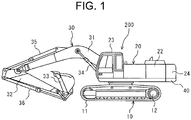
- FIG. 1 shows one embodiment of a hydraulic excavator 100 that is one of the construction machines related to the present invention.
- this hydraulic excavator 100 is configured mainly of an undercarriage 10, and a revolving upperstructure 20 that is turnably arranged on the undercarriage 10.
- the undercarriage 10 includes a pair of crawlers 11 that are positioned in parallel with a travel base frame which is not illustrated in Fig. 1 , and the crawler 11 is provided with a travel motor 12 of a hydraulic drive type that is for driving each crawler for traveling.
- the revolving upperstructure 20 is configured mainly of an engine chamber 22 that is installed on a revolving upperstructure frame 40, a cab 23 that is arranged on the front left side of this engine chamber 22, a front working mechanism 30 that extends forward from the right side of this cab 23, and a counterweight 24 that is arranged behind the engine chamber 22 so as to keep weight balance with this front working mechanism 30.
- the front working mechanism 30 is configured mainly of a boom 31 that extends forward from the revolving upperstructure frame 40 side, an arm 32 that is swingably arranged at the distal end of this boom 31, and a bucket 33 that is swingably arranged at the distal end of this arm 32, and these boom 31, arm 32, and bucket 33 respectively operate by a boom cylinder 34, an arm cylinder 35, and a bucket cylinder 36 which respectively expand/shrink by the hydraulic pressure.
- these boom cylinder 34, arm cylinder 35, bucket cylinder 36, travel motors 12, and the like are configured to operate by a pressure oil (hydraulic oil) that is supplied from a main pump 50 ( Fig. 2 ) that is arranged within the engine chamber 22.
- This main pump 50 is connected to an engine 70 through a transmission 60 as shown in Fig. 2 , and is configured to suck the hydraulic oil within a hydraulic oil tank 80 through suction pipe 81a, a suction tank 82, and a suction pipe 83 by a drive force of the engine 70, and to feed the pressure oil to actuators of the boom cylinder 34, the arm cylinder 35, the bucket cylinder 36, the travel motors 12, and the like described above.
- This main pump 50 is arranged by plural numbers for one transmission 60, and it is configured that the hydraulic oil within the hydraulic oil tank 80 dividedly flows from the suction tank 82 to plural suction pipes 83, 83... and is sucked by respective main pumps 50, 50....
- the transmission 60 is a speed change gear that increases or reduces the speed of rotational drive of the engine 70 and transmits the rotational drive to the respective main pumps 50, 50... by gears, and it is configured that the lubricating oil (transmission oil) is constantly supplied by a lubrication pump 61 when the transmission 60 is operated.
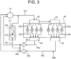
- Fig. 3 is a schematic view that shows a flow of the transmission oil in this transmission 60. As shown in Fig. 3 , it is configured that the transmission oil sent out from the lubrication pump 61 flows dividedly to respective narrow pipes 62a, 62a... from a flow divide-cum-relay block 62 through an oil pipe 61a, and is supplied to respective bearings B, B... and gears to lubricate them.
- this flow divide-cum-relay block 62 flows to a flow divide block 63 as it is, branches from this flow divide block 63 to respective narrow pipes 63a, 63a..., and is supplied to other respective bearings B, B... and gears to lubricate them.
- the transmission oil having been supplied to the respective bearings B, B... and the gears flows to confluence blocks 64, 65 through the respective narrow pipes 62b, 62b..., 63b, 63b... to be merged, and returns to the lubrication pump 61 side through respective return oil pipes 64a, 65a.
- the transmission oil circulates within a circulation channel 60A that is formed of the oil pipe 61a, the narrow pipes 62a, 62a..., 62b, 62b..., 63a, 63a..., 63b, 63b..., and the return oil pipes 64a, 65a.
- suction filters 64b, 65b are arranged respectively, and it is configured that, when a solid object such as iron powder is mixed into the transmission oil, the solid object is filtered and separated.
- a bypass pipe 66 is connected between the oil pipe 61 and the return oil pipes 64a, 65a in this circulation channel 60A so as to detour around the lubrication pump 61, and it is configured that the transmission oil flowing through the return oil pipes 64a, 65a and immediately after coming out of the suction filters 64b, 65b is drawn out through a connection pipe 66a, and is made flow directly to the oil pipe 61 in the same direction.
- a preheating unit 67 is arranged which integrates a bypass pump 67a and a heater 67b of an electro-thermal type, and it is configured that the transmission oil is drawn out to the bypass pipe 66 side by the bypass pump 67a, and that the transmission oil having been drawn out is heated by the heater 67b and is thereafter made flow to the oil pipe 61 side.
- a circulation channel 70A through which the cooling water flows is formed in the engine 70 also.
- This circulation channel 70A is configured of a first circulation channel 71a that is formed within the engine 70, and a second circulation channel 71b that is formed between the engine 70 and a radiator.
- the cooling water is circulated within the engine 70 by a circulation pump 72 that is arranged in the first circulation channel 71a, when the temperature of the cooling water rises, a thermostat 73 works to make the first circulation channel 71a and the second circulation channel 71b communicate to each other to make the cooling water having become hot flow to the second circulation channel 71b side, and the cooling water is air-cooled by a radiator 74 and a cooling fan 75 and is returned to the first circulation channel 71a side.
- a bypass pipe 76 and a preheating unit 77 are arranged also in the circulation channel 70A of this engine 70 so as to detour around the circulation pump 72, and it is configured that the cooling water that flows though this circulation channel 70A is drawn out, is heated, and is returned to the circulation channel 70A in the same direction.
- this preheating unit 77 is also configured of one that integrates a bypass pump 77a and a heater 77b of an electro-thermal type.
- the hydraulic oil tank 80 and the suction tank 82 are also connected to each other in parallel with the suction pipe 81a by a bypass pipe 84 that includes a preheating unit 85, and it is configured that the hydraulic oil within the suction tank 82 is drawn out by a bypass pump 84a of the preheating unit 85, is heated by a heater 84b of an electro-thermal type, and is directly returned to the middle of the hydraulic oil tank 80.
- a circulation channel of a small loop is formed in parallel with the circulation channel 80A of a large loop by this bypass pipe 84.
- controller 90 is configured to control these respective preheating units 67, 77, 85 based on input signals from various kind of sensors (oil temperature sensor, air temperature sensor) and an engine control unit (ECU) which are not illustrated in Fig. 2 , and so on.
- Fig. 4 shows a flow of control with respect to the preheating unit 67 for the transmission 60 by this controller 90.
- this controller 90 determines whether or not the engine 70 is stopped in the first step S100, finishes the process when it is determined that the engine 70 is not stopped (NO), and shifts to the next step S102 when it is determined that the engine 70 is stopped (YES).
- step S102 whether or not the outside temperature is below -10°C is determined based on an input value from the temperature sensor, the process is finished as it is when it is determined not to be -10°C, namely -10°C or above and there is no risk of a freeze of the transmission oil (NO), however, when it is determined that the outside temperature is below -10°C and there is a risk of a freeze (YES), the process shifts to the next step S104.
- step S104 whether or not the temperature (oil temperature) of the transmission oil is below 30°C is determined based on an input value from the oil temperature sensor, when it is determined to be below 30°C (YES), the process shifts to the step S108, the heater 67b and the bypass pump 67a of the preheating unit 67 are started, and the transmission oil within the circulation channel 60A is drawn out from the upstream side of the lubrication pump 61 to the bypass pipe 66 side as shown in Fig. 2 , is heated by the heater 67b, and is sent out to the downstream side of the lubrication pump 61.
- the transmission oil having been sent out to the downstream side of the lubrication pump 61 does not flow to the lubrication pump 61 side but flows from the oil pipe 61a to the side of the flow divide-cum-relay block 62 and the flow divide block 63, passes through the respective narrow pipes 62a, 62a..., 63a, 63a..., the respective bearings B, B... and gears, and the respective narrow pipes 62b, 62b..., 63b, 63b...
- the process shifts to the next step S106, only the bypass pump 67a of the preheating unit 67 is started, and the transmission oil within the circulation channel 60A is drawn out from the upstream side of the lubrication pump 61 to the bypass pipe 66 side and is sent out to the downstream side of the lubrication pump 61.
- the transmission oil whose oil temperature is 30°C or above is circulated in the inside of the circulation channel 60A, the entire transmission 60 is kept at a proper temperature by the heat of the transmission oil itself, therefore wasteful heating by the heater 67b can be prevented, and electric power consumption can be suppressed.
- next step S110 whether or not the oil temperature has become lower than 30°C by drop of the outside air temperature and the like during circulation only by the lubrication pump 61 is determined, the process shifts to the step S113 when it is determined that the oil temperature has not become lower than 30°C (NO), but when it is determined that the oil temperature has become lower than 30°C (YES), the process shifts to the step S112, and the heater 67b of the electro-thermal type is started (energized).
- the heater 67b of the electro-thermal type is started (energized).
- next step S114 whether or not the engine 70 has started is determined based on an input signal from the ECU and the like not illustrated. Circulation of the transmission oil is continued as it is when it is determined that the engine 70 has not started (NO), but when it is determined that the engine 70 has started (YES), the process shifts to the next step S116, the heater 67b and the bypass pump 67a are stopped, circulation and heating of the transmission oil by the preheating unit 67 are stopped, and the process is finished.
- step S113 in the step S113 described above also, whether or not the engine 70 has started is determined based on an input signal from the ECU and the like not illustrated, circulation of the transmission oil only by the bypass pump 67a is continued as it is when it is determined that the engine 70 has not started (NO), but when it is determined that the engine 70 has started (YES), the process shifts to the next step S115, the bypass pump 67a is stopped, thereby circulation of the transmission oil by the preheating unit 67 is stopped, and the process is finished.
- a freeze of the hydraulic oil and the cooling water can be efficiently prevented.
- the starting temperature thereof is adjusted properly according to the freezing temperature of each oil kind, more efficient preheating processing can be effected.
- the freezing temperature of the transmission oil and the cooling water is -10°C and the freezing temperature of the hydraulic oil is -20°C
- preheating processing only by the preheating units 67 and 77 is executed when the outside air temperature becomes -10°C and preheating processing by the preheating unit 85 on the hydraulic oil tank 80 side is further executed when the outside air temperature becomes -20°C, wasteful electric power consumption can be further suppressed.
- the engine 70 stops and circulation of the fluid such as the transmission oil stops in the circulation channel 60A of the transmission 60 and so on, the fluid can be heated while being circulated in the same direction through the bypass pipe 66, and therefore the entire circulation channel 60A can be efficiently preheated.
- the bypass pipe 66 is branched with respect to the existing circulation channel 60A and the preheating unit 67 is attached to the bypass pipe 66, easy retrofitting to an existing construction machine is possible, and therefore sound versatility can be exerted.
- Fig. 5 shows a configuration example of a related art which does not include such preheating unit as that of the present invention.
- the bypass pipe 76 is provided in the circulation channel 70A similarly to the present invention, the cooling water is drawn out from the circulation channel 70A to the bypass pipe 76 side and is heated, however, since the heating means uses a heater 78 of a combustion type, sound combustion is hard in a place such as the highlands where the oxygen concentration is low, and the configuration thereof becomes complicated.
- plural bar heaters 86, 86 are attached to the suction tank 82, are energized, and are intended to heat the hydraulic oil within the suction tank 82, however, with such configuration, the heating position is local, and it is hard to efficiently heat the entirety. Furthermore, in the transmission 60 in which seizure and the like caused by a freeze of the lubricating oil (transmission oil) should be prevented, the transmission 60 could not be efficiently preheated.
Landscapes
- Engineering & Computer Science (AREA)
- General Engineering & Computer Science (AREA)
- Mechanical Engineering (AREA)
- Chemical & Material Sciences (AREA)
- Combustion & Propulsion (AREA)
- Structural Engineering (AREA)
- Civil Engineering (AREA)
- Mining & Mineral Resources (AREA)
- Transportation (AREA)
- General Details Of Gearings (AREA)
- Analytical Chemistry (AREA)
- Physics & Mathematics (AREA)
- Fluid Mechanics (AREA)
Abstract
Description
- The present invention relates to a construction machine provided with a preheating unit for preheating fluid such as the cooling water of a prime mover (an engine and an electric motor), a transmission oil, and a hydraulic oil, and a preheating method of the construction machine.
- In a construction machine such as a hydraulic excavator, various kinds of fluid (liquid) is used such as the cooling water of a prime mover (an engine and an electric motor), a lubricating oil of a transmission (a transmission oil), and a hydraulic oil of an actuator. When such construction machine is used in an extremely cold region of -40°C or below, for example, there is a case that, once the prime mover is stopped, such fluid is frozen, and restarting becomes hard. Also, when the prime mover is started in a state the lubricating oil such as the transmission oil is frozen and the lubricating performance thereof is lost, there is a risk of breakage of the transmission, hydraulic pump, actuator and the like.
- As a technology for improving the engine starting performance under a cold condition, in PATENT LITERATURE 1 described below, for example, such technology is proposed that a heater is provided in the suction piping that connects a hydraulic pump and a hydraulic oil tank to each other, a hydraulic oil within the suction piping is warmed up before starting an engine, and thereby the starting performance of the engine is improved. Moreover, in PATENT LITERATURE 2 described below, such technology is proposed that preheaters are provided in an engine, a cab, and the like, and the engine, the cab, and the like are preheated by these preheaters. Further, in PATENT LITERATURE 3 described below, such technology is proposed that a hydraulic oil of the entire vehicle body is warmed by driving both of a main electric motor and an electric heater, the main electric motor driving the vehicle body.
-
- PATENT LITERATURE 1:
JP-A No. Heisei 8-284907 - PATENT LITERATURE 2:
JP-A No. 2000-80679 - PATENT LITERATURE 3: Japanese Patent No.
5271500 - In the meantime, in such preheating methods of the related arts as described above, there are such problems as described below. That is to say, according to the technology shown in PATENT LITERATURE 1 described above, since the hydraulic oil is warmed in a restricted area of only the suction piping, sufficient preheating is hard in an extremely cold region of -40°C or below. In particular, in an electromotive type hydraulic excavator, a transmission for amplifying the pump rotational speed is arranged at a position for connecting a main electric motor and a pump to each other.
- This transmission employs a forced circulation method that uses a pump operated by the electric motor of the transmission, and includes plural narrow pipes for directly supplying the lubricating oil to bearings and gears. Therefore, when the viscosity of the transmission oil becomes high and the mission oil is frozen in the inside of these narrow pipes and supply becomes insufficient or stops, there is a risk that defective lubrication occurs locally, and the bearings and the gears are seized and broken. Therefore, it is necessary to sufficiently preheat not only the suction piping of the hydraulic oil but also this transmission.
- In contrast, since such technology as shown in PATENT LITERATURE 2 described above is a method of heating the cooling water of an engine by a combustion type heater, in a region of high elevation exceeding 2,000 m above the sea level, the oxygen concentration is low, and sound combustion is hard. Moreover, according to such technology as shown in PATENT LITERATURE 3 described above, there is a problem that, although the heating function is sufficient, when the main electric motor is stopped because of maintenance and the like, the main electric motor does not function.
- Therefore, the present invention has been worked out for solving these problems, and its object is to provide a construction machine provided with a novel preheating unit that can efficiently preheat the entire circulation channel where fluid flows, and a preheating method of the construction machine.
- In order to solve the problems described above, a first invention is a construction machine including a bypass channel in parallel with a circulation channel that circulates fluid, and a preheating unit that consists of a heater and a bypass pump in the middle of bypass channel. According to such configuration, even in a state circulation of the fluid may stop in the circulation channel, the fluid can be heated while the fluid is circulated through the bypass channel, and therefore the entire circulation channel can be efficiently preheated. Also, since retrofitting to an existing circulation channel is possible, sound versatility can be exerted.
- A second invention is the construction machine of the first invention in which the bypass channel is arranged between an upstream side and a downstream side of a circulation pump that is arranged in the circulation channel, and the bypass pump of the preheating unit circulates the fluid in the direction same to that of the pump of the circulation channel. According to such configuration, even in a state the circulation pump may stop, the fluid can be heated while the fluid is positively circulated in the direction same to that of the pump of the circulation channel, and therefore the entire circulation channel can be efficiently preheated.
- A third invention is the construction machine of the first invention in which the circulation channel is configured to circulate a lubricating oil between a hydraulic oil tank and a main pump, the bypass channel is arranged in the circulation channel that is provided between the hydraulic oil tank and the main pump, and the circulation channel and the bypass channel form a circulation loop of the hydraulic oil. According to such configuration, since a circulation channel of a small loop can be formed by the bypass channel in a circulation channel of a large loop that is formed between the hydraulic oil tank and the main pump, even in a state the main pump may stop, the hydraulic oil within the hydraulic oil tank can be circulated by a small heat quantity while being preheated through the bypass channel.
- A fourth invention is the construction machine of the first or second invention in which the circulation channel is a circulation channel that circulates a transmission oil for a transmission. According to such configuration, even in a state the transmission and the circulation pump of the transmission may stop, the transmission oil can be heated while being positively circulated within the circulation channel of the transmission, and therefore the entire transmission can be efficiently preheated.
- A fifth invention is the construction machine of the first to third invention in which the circulation channel is a circulation channel that circulates cooling water for a prime mover. According to such configuration, even in a state the prime mover such as an engine (internal combustion engine) and an electric motor and the circulation pump of the prime mover may stop, since the cooling water can be heated while being positively circulated within the circulation channel thereof, the entire engine can be efficiently preheated.
- A sixth invention is the construction machine of the third invention in which the bypass channel connects the hydraulic oil tank and a suction tank to each other. According to such configuration, even in a state circulation of the hydraulic oil within the hydraulic oil tank may stop, while the hydraulic oil is positively circulated between the hydraulic oil tank and the suction tank, the entirety of them can be efficiently preheated.
- A seventh invention is a preheating method with respect to the first to sixth invention in which an outside air temperature and temperature of the fluid when the prime mover is stopped are measured, heating of the fluid by the heater of the preheating unit and fluid circulation by the bypass pump are executed when the outside air temperature is lower than a first predetermined value T1 and the temperature of the fluid is lower than a second predetermined value T2 (where T1<T2), and only fluid circulation by the bypass pump of the preheating unit is executed when the outside air temperature is lower than the first predetermined value T1 and the temperature of the fluid is equal to or higher than the second predetermined value T2. According to such preheating method, since the fluid (oil kind) can be heated only when preheating is required, effective preheating without a loss can be effected.
- According to the present invention, even in a state the engine stops and circulation of the fluid such as the transmission oil stops in the circulation channel of the transmission and the like, the fluid can be heated through the bypass channel while being circulated, and therefore the entire circulation channel can be efficiently preheated. Moreover, since it is constructed so that the bypass channel is branched from the existing circulation channel and the preheating unit is attached to the bypass channel, the preheating unit can be easily retrofitted also to an existing construction machine. Further, since circulation and heating of the fluid by the preheating unit are finely controlled according to the change of the outside temperature, the oil temperature, and the like which occurs while the engine is stopped, efficient preheating processing can be effected while suppressing wasteful energy consumption.
-
- [
Fig. 1] Fig. 1 is a vertical cross-sectional view that shows one embodiment of a construction machine (hydraulic excavator) 100 related to the present invention. - [
Fig. 2] Fig. 2 is a schematic view that shows a configuration of the vicinity of a power train of the construction machine (hydraulic excavator) 100. - [
Fig. 3] Fig. 3 is a schematic view that shows a configuration of acirculation channel 60A of atransmission 60. - [
Fig. 4] Fig. 4 is a flowchart that shows a flow of the preheating control using apreheating unit 67 related to the present invention. - [
Fig. 5] Fig. 5 is a schematic view that shows a configuration of the vicinity of a power train of a construction machine (hydraulic excavator) of a related art. - Next, an embodiment of the present invention will be explained referring to the attached drawings.
Fig. 1 shows one embodiment of ahydraulic excavator 100 that is one of the construction machines related to the present invention. As shown inFig. 1 , thishydraulic excavator 100 is configured mainly of anundercarriage 10, and a revolvingupperstructure 20 that is turnably arranged on theundercarriage 10. Theundercarriage 10 includes a pair ofcrawlers 11 that are positioned in parallel with a travel base frame which is not illustrated inFig. 1 , and thecrawler 11 is provided with atravel motor 12 of a hydraulic drive type that is for driving each crawler for traveling. - In contrast, the revolving
upperstructure 20 is configured mainly of anengine chamber 22 that is installed on a revolvingupperstructure frame 40, acab 23 that is arranged on the front left side of thisengine chamber 22, afront working mechanism 30 that extends forward from the right side of thiscab 23, and acounterweight 24 that is arranged behind theengine chamber 22 so as to keep weight balance with thisfront working mechanism 30. - The
front working mechanism 30 is configured mainly of aboom 31 that extends forward from the revolvingupperstructure frame 40 side, anarm 32 that is swingably arranged at the distal end of thisboom 31, and abucket 33 that is swingably arranged at the distal end of thisarm 32, and theseboom 31,arm 32, andbucket 33 respectively operate by aboom cylinder 34, anarm cylinder 35, and abucket cylinder 36 which respectively expand/shrink by the hydraulic pressure. Moreover, theseboom cylinder 34,arm cylinder 35,bucket cylinder 36,travel motors 12, and the like are configured to operate by a pressure oil (hydraulic oil) that is supplied from a main pump 50 (Fig. 2 ) that is arranged within theengine chamber 22. - This
main pump 50 is connected to anengine 70 through atransmission 60 as shown inFig. 2 , and is configured to suck the hydraulic oil within ahydraulic oil tank 80 throughsuction pipe 81a, asuction tank 82, and a suction pipe 83 by a drive force of theengine 70, and to feed the pressure oil to actuators of theboom cylinder 34, thearm cylinder 35, thebucket cylinder 36, thetravel motors 12, and the like described above. Thismain pump 50 is arranged by plural numbers for onetransmission 60, and it is configured that the hydraulic oil within thehydraulic oil tank 80 dividedly flows from thesuction tank 82 to plural suction pipes 83, 83... and is sucked by respectivemain pumps - Then, it is configured that the hydraulic oil of a high pressure discharged from the respective
main pumps hydraulic oil tank 80 throughreturn pipe 81b. In other words, between thishydraulic oil tank 80 and the respectivemain pumps circulation channel 80A of a large loop in one direction is formed by thesuction pipe 81a, thesuction tank 82, the suction pipes 83, and thereturn pipe 81b. - The
transmission 60 is a speed change gear that increases or reduces the speed of rotational drive of theengine 70 and transmits the rotational drive to the respectivemain pumps lubrication pump 61 when thetransmission 60 is operated.Fig. 3 is a schematic view that shows a flow of the transmission oil in thistransmission 60. As shown inFig. 3 , it is configured that the transmission oil sent out from thelubrication pump 61 flows dividedly to respectivenarrow pipes relay block 62 through anoil pipe 61a, and is supplied to respective bearings B, B... and gears to lubricate them. Furthermore, it is configured that a part of the oil having flown to this flow divide-cum-relay block 62 flows to aflow divide block 63 as it is, branches from thisflow divide block 63 to respectivenarrow pipes - Further, it is configured that the transmission oil having been supplied to the respective bearings B, B... and the gears flows to confluence blocks 64, 65 through the respective
narrow pipes lubrication pump 61 side through respectivereturn oil pipes circulation channel 60A that is formed of theoil pipe 61a, thenarrow pipes return oil pipes return oil pipes suction filters - Also, a
bypass pipe 66 is connected between theoil pipe 61 and thereturn oil pipes circulation channel 60A so as to detour around thelubrication pump 61, and it is configured that the transmission oil flowing through thereturn oil pipes connection pipe 66a, and is made flow directly to theoil pipe 61 in the same direction. Further, in thisbypass pipe 66, a preheatingunit 67 is arranged which integrates abypass pump 67a and aheater 67b of an electro-thermal type, and it is configured that the transmission oil is drawn out to thebypass pipe 66 side by thebypass pump 67a, and that the transmission oil having been drawn out is heated by theheater 67b and is thereafter made flow to theoil pipe 61 side. - In contrast, as shown in
Fig. 2 , acirculation channel 70A through which the cooling water flows is formed in theengine 70 also. Thiscirculation channel 70A is configured of afirst circulation channel 71a that is formed within theengine 70, and asecond circulation channel 71b that is formed between theengine 70 and a radiator. Also, it is configured that the cooling water is circulated within theengine 70 by acirculation pump 72 that is arranged in thefirst circulation channel 71a, when the temperature of the cooling water rises, athermostat 73 works to make thefirst circulation channel 71a and thesecond circulation channel 71b communicate to each other to make the cooling water having become hot flow to thesecond circulation channel 71b side, and the cooling water is air-cooled by a radiator 74 and a coolingfan 75 and is returned to thefirst circulation channel 71a side. - Further, as shown in
Fig. 2 , similarly to thetransmission 60 described above, abypass pipe 76 and a preheating unit 77 are arranged also in thecirculation channel 70A of thisengine 70 so as to detour around thecirculation pump 72, and it is configured that the cooling water that flows though thiscirculation channel 70A is drawn out, is heated, and is returned to thecirculation channel 70A in the same direction. Furthermore, this preheating unit 77 is also configured of one that integrates a bypass pump 77a and aheater 77b of an electro-thermal type. - Moreover, as shown in
Fig. 2 , thehydraulic oil tank 80 and thesuction tank 82 are also connected to each other in parallel with thesuction pipe 81a by a bypass pipe 84 that includes a preheatingunit 85, and it is configured that the hydraulic oil within thesuction tank 82 is drawn out by a bypass pump 84a of the preheatingunit 85, is heated by a heater 84b of an electro-thermal type, and is directly returned to the middle of thehydraulic oil tank 80. In other words, it is configured that a circulation channel of a small loop is formed in parallel with thecirculation channel 80A of a large loop by this bypass pipe 84. - Moreover, operation of these
respective preheating units respective preheating units Fig. 2 , and so on. -
Fig. 4 shows a flow of control with respect to the preheatingunit 67 for thetransmission 60 by this controller 90. First, this controller 90 determines whether or not theengine 70 is stopped in the first step S100, finishes the process when it is determined that theengine 70 is not stopped (NO), and shifts to the next step S102 when it is determined that theengine 70 is stopped (YES). - In the step S102, whether or not the outside temperature is below -10°C is determined based on an input value from the temperature sensor, the process is finished as it is when it is determined not to be -10°C, namely -10°C or above and there is no risk of a freeze of the transmission oil (NO), however, when it is determined that the outside temperature is below -10°C and there is a risk of a freeze (YES), the process shifts to the next step S104. In the step S104, whether or not the temperature (oil temperature) of the transmission oil is below 30°C is determined based on an input value from the oil temperature sensor, when it is determined to be below 30°C (YES), the process shifts to the step S108, the
heater 67b and thebypass pump 67a of the preheatingunit 67 are started, and the transmission oil within thecirculation channel 60A is drawn out from the upstream side of thelubrication pump 61 to thebypass pipe 66 side as shown inFig. 2 , is heated by theheater 67b, and is sent out to the downstream side of thelubrication pump 61. - At this time, in the
lubrication pump 61 in suspension, since the flow of the transmission oil is stopped, the transmission oil having been sent out to the downstream side of thelubrication pump 61 does not flow to thelubrication pump 61 side but flows from theoil pipe 61a to the side of the flow divide-cum-relay block 62 and theflow divide block 63, passes through the respectivenarrow pipes narrow pipes return oil pipes bypass pipe 66, is heated again by theheater 67b, and comes to circulate within thecirculation channel 60A as shown inFig. 3 . Thus, since theentire transmission 60 is kept warm at a proper temperature, even when the outside air temperature becomes an extremely cold state of -40°C or below, for example, such problems that the transmission oil freezes and so on can be prevented. - On the other hand, when it is determined that the temperature (oil temperature) of the transmission oil is not below 30°C, namely, is 30°C or above (NO) in the step S104 described above, the process shifts to the next step S106, only the
bypass pump 67a of the preheatingunit 67 is started, and the transmission oil within thecirculation channel 60A is drawn out from the upstream side of thelubrication pump 61 to thebypass pipe 66 side and is sent out to the downstream side of thelubrication pump 61. Thus, the transmission oil whose oil temperature is 30°C or above is circulated in the inside of thecirculation channel 60A, theentire transmission 60 is kept at a proper temperature by the heat of the transmission oil itself, therefore wasteful heating by theheater 67b can be prevented, and electric power consumption can be suppressed. - In the next step S110, whether or not the oil temperature has become lower than 30°C by drop of the outside air temperature and the like during circulation only by the
lubrication pump 61 is determined, the process shifts to the step S113 when it is determined that the oil temperature has not become lower than 30°C (NO), but when it is determined that the oil temperature has become lower than 30°C (YES), the process shifts to the step S112, and theheater 67b of the electro-thermal type is started (energized). Thus, since the transmission oil having been drawn out to thebypass pipe 66 is heated and is made flow in thecirculation channel 60A, a freeze of the transmission oil caused by drop of the oil temperature can be prevented more positively. Further, it is also possible to stop only thisheater 67b when the oil temperature exceeds 30°C to a large degree by heating of thisheater 67b, and so on. - In the next step S114, whether or not the
engine 70 has started is determined based on an input signal from the ECU and the like not illustrated. Circulation of the transmission oil is continued as it is when it is determined that theengine 70 has not started (NO), but when it is determined that theengine 70 has started (YES), the process shifts to the next step S116, theheater 67b and thebypass pump 67a are stopped, circulation and heating of the transmission oil by the preheatingunit 67 are stopped, and the process is finished. - On the other hand, in a similar manner, in the step S113 described above also, whether or not the
engine 70 has started is determined based on an input signal from the ECU and the like not illustrated, circulation of the transmission oil only by thebypass pump 67a is continued as it is when it is determined that theengine 70 has not started (NO), but when it is determined that theengine 70 has started (YES), the process shifts to the next step S115, thebypass pump 67a is stopped, thereby circulation of the transmission oil by the preheatingunit 67 is stopped, and the process is finished. Thus, when circulation and heating of the transmission oil by the preheatingunit 67 are finely controlled according to the change of the outside air temperature, the oil temperature, and the like which occurs while theengine 70 is stopped, efficient preheating processing can be effected while suppressing wasteful electric power consumption. - Moreover, by executing control similar to the above also in the other preheating
units 77, 85, a freeze of the hydraulic oil and the cooling water can be efficiently prevented. In this case, when the starting temperature thereof is adjusted properly according to the freezing temperature of each oil kind, more efficient preheating processing can be effected. For example, in a case where the freezing temperature of the transmission oil and the cooling water is -10°C and the freezing temperature of the hydraulic oil is -20°C, if preheating processing only by the preheatingunits 67 and 77 is executed when the outside air temperature becomes -10°C and preheating processing by the preheatingunit 85 on thehydraulic oil tank 80 side is further executed when the outside air temperature becomes -20°C, wasteful electric power consumption can be further suppressed. - As described above, in the present invention, even in a state the
engine 70 stops and circulation of the fluid such as the transmission oil stops in thecirculation channel 60A of thetransmission 60 and so on, the fluid can be heated while being circulated in the same direction through thebypass pipe 66, and therefore theentire circulation channel 60A can be efficiently preheated. Moreover, since it has a construction that thebypass pipe 66 is branched with respect to the existingcirculation channel 60A and the preheatingunit 67 is attached to thebypass pipe 66, easy retrofitting to an existing construction machine is possible, and therefore sound versatility can be exerted. Further, as described above, when circulation and heating of the transmission oil by the preheatingunit 67 are finely controlled according to the change of the outside air temperature, the oil temperature, and the like which occurs while theengine 70 is stopped, efficient preheating processing can be effected while suppressing wasteful electric power consumption. -
Fig. 5 shows a configuration example of a related art which does not include such preheating unit as that of the present invention. In other words, with respect to preheating of the cooling water of theengine 70, thebypass pipe 76 is provided in thecirculation channel 70A similarly to the present invention, the cooling water is drawn out from thecirculation channel 70A to thebypass pipe 76 side and is heated, however, since the heating means uses aheater 78 of a combustion type, sound combustion is hard in a place such as the highlands where the oxygen concentration is low, and the configuration thereof becomes complicated. Further,plural bar heaters suction tank 82, are energized, and are intended to heat the hydraulic oil within thesuction tank 82, however, with such configuration, the heating position is local, and it is hard to efficiently heat the entirety. Furthermore, in thetransmission 60 in which seizure and the like caused by a freeze of the lubricating oil (transmission oil) should be prevented, thetransmission 60 could not be efficiently preheated. - Moreover, although it was configured that the
transmission 60 was driven by theengine 70 in the present embodiment, it is a matter of course that the present invention can be applied in a similar manner also to a case an electric motor is used as a prime mover instead of thisengine 70. -
- 100 ... Construction machine (hydraulic excavator)
- 50 ... Main pump
- 60 ... Transmission
- 60A, 70A, 80A ... Circulation channel
- 61 ... Lubrication pump
- 66, 76, 84 ... Bypass pipe (channel)
- 67, 77, 85 ... Preheating unit
- 67b, 77b, 84b ... Electro-thermal type heater
- 67a, 77a, 84a ... Bypass pump
- 70 ... Engine (prime mover)
- 72 ... Circulation pump
- 80 ... Hydraulic oil tank
- 81a ... Suction pipe
- 81b ... Return pipe
- 82 ... Suction tank
- 83 ... Suction pipe
- 90 ... Controller
Claims (7)
- A construction machine, comprising:a bypass channel in parallel with a circulation channel that circulates fluid; anda preheating unit that consists of a heater and a bypass pump in the middle of bypass channel.
- The construction machine according to Claim 1,
wherein the bypass channel is arranged between an upstream side and a downstream side of a circulation pump that is arranged in the circulation channel, and
the bypass pump of the preheating unit circulates the fluid in the direction same to that of the pump of the circulation channel. - The construction machine according to Claim 1,
wherein the circulation channel is configured to circulate a lubricating oil between a hydraulic oil tank and a main pump,
the bypass channel is arranged in the circulation channel that is provided between the hydraulic oil tank and the main pump, and
the circulation channel and the bypass channel form a circulation loop of the hydraulic oil. - The construction machine according to Claim 1 or 2, wherein the circulation channel is a circulation channel that circulates a transmission oil for a transmission.
- The construction machine according to Claim 1 or 2, wherein the circulation channel is a circulation channel that circulates cooling water for a prime mover.
- The construction machine according to Claim 3, wherein the bypass channel connects the hydraulic oil tank and a suction tank to each other.
- A preheating method of the construction machine according to any one of Claims 1 to 6, comprising:measuring an outside air temperature and a temperature of the fluid when the prime mover is stopped;executing heating of the fluid by the heater of the preheating unit and fluid circulation by the bypass pump when the outside air temperature is lower than a first predetermined value T1 and the temperature of the fluid is lower than a second predetermined value T2 (where T1<T2); andexecuting only fluid circulation by the bypass pump of the preheating unit when the outside air temperature is lower than the first predetermined value T1 and the temperature of the fluid is equal to or higher than the second predetermined value T2.
Applications Claiming Priority (1)
| Application Number | Priority Date | Filing Date | Title |
|---|---|---|---|
| PCT/JP2015/065097 WO2016189653A1 (en) | 2015-05-26 | 2015-05-26 | Construction machine provided with preheating unit and method for preheating said machine |
Publications (2)
| Publication Number | Publication Date |
|---|---|
| EP3306113A1 true EP3306113A1 (en) | 2018-04-11 |
| EP3306113A4 EP3306113A4 (en) | 2019-01-09 |
Family
ID=57392642
Family Applications (1)
| Application Number | Title | Priority Date | Filing Date |
|---|---|---|---|
| EP15893288.9A Withdrawn EP3306113A4 (en) | 2015-05-26 | 2015-05-26 | Construction machine provided with preheating unit and method for preheating said machine |
Country Status (4)
| Country | Link |
|---|---|
| US (1) | US10407869B2 (en) |
| EP (1) | EP3306113A4 (en) |
| CN (1) | CN107407304B (en) |
| WO (1) | WO2016189653A1 (en) |
Families Citing this family (15)
| Publication number | Priority date | Publication date | Assignee | Title |
|---|---|---|---|---|
| US9303715B2 (en) | 2013-03-10 | 2016-04-05 | Oshkosh Defense, Llc | Limiting system for a vehicle suspension component |
| US10414266B1 (en) * | 2017-04-28 | 2019-09-17 | Oshkosh Defense, Llc | Vehicle cooling systems and methods |
| US12491943B1 (en) | 2013-03-10 | 2025-12-09 | Oshkosh Defense, Llc | Systems and methods for a military vehicle |
| JP2019116198A (en) * | 2017-12-27 | 2019-07-18 | ヤマハ発動機株式会社 | vehicle |
| DE102018109568A1 (en) * | 2018-04-20 | 2019-10-24 | Wacker Neuson Linz Gmbh | Work vehicle with a hydraulic circuit with activated as required flow resistance |
| CN108978766A (en) * | 2018-06-28 | 2018-12-11 | 柳州柳工挖掘机有限公司 | Hydraulic crawler excavator cooling system arragement construction |
| US10704433B2 (en) * | 2018-08-23 | 2020-07-07 | Ford Global Technologies, Llc | Engine oil warm up using inductive heating |
| US11137002B2 (en) * | 2019-05-01 | 2021-10-05 | Oshkosh Corporation | Temperature regulation system for vehicle hydraulic system |
| KR102140567B1 (en) * | 2020-02-27 | 2020-08-03 | 전현철 | Oil circulation system for preheating, lubrication and cooling used for internal combustion engine and industrial facilities |
| CN113153864B (en) * | 2020-12-23 | 2024-04-12 | 曾俊 | Protective device with good cooling effect and protective method thereof |
| US11448117B2 (en) * | 2021-02-02 | 2022-09-20 | Fca Us Llc | Auxiliary coolant pump with bypass |
| CN113154241B (en) * | 2021-04-28 | 2022-04-29 | 三一重机有限公司 | Storage container and heating system |
| CN114704348A (en) * | 2022-04-19 | 2022-07-05 | 奇瑞汽车股份有限公司 | Engine oil collector, engine oil heating method and engine lubricating system |
| CN115263488B (en) * | 2022-07-20 | 2023-07-28 | 广州汽车集团股份有限公司 | Oil pump control method, device, electronic equipment and storage medium |
| CN115507169B (en) * | 2022-09-27 | 2026-04-14 | 中联重科股份有限公司 | Gearbox oil way system, crane and starting method of gearbox oil way system |
Family Cites Families (11)
| Publication number | Priority date | Publication date | Assignee | Title |
|---|---|---|---|---|
| JPS58137106U (en) * | 1982-03-12 | 1983-09-14 | 日立建機株式会社 | Hydraulic oil heating device |
| DE4232542C1 (en) * | 1993-11-19 | 1994-01-27 | Orenstein & Koppel Ag | Hydraulic-excavator oil-cooling circuit - has buffer-stores hot oil separately before pumping through cooled into storage tank |
| JPH08284907A (en) | 1995-04-18 | 1996-11-01 | Hitachi Constr Mach Co Ltd | Hydraulic oil warming-up device for construction machine |
| JP2000080679A (en) | 1998-09-04 | 2000-03-21 | Hitachi Constr Mach Co Ltd | Construction machinery |
| US6354089B1 (en) * | 2000-03-08 | 2002-03-12 | Case Corporation | Apparatus and method for cooling multiple fluids on a work vehicle |
| JP2005188434A (en) * | 2003-12-26 | 2005-07-14 | Hitachi Constr Mach Co Ltd | Drive protection device for construction machinery |
| JP5271500B2 (en) | 2007-03-19 | 2013-08-21 | 日立建機株式会社 | Battery-powered construction machinery |
| DE102008018532A1 (en) | 2008-04-08 | 2009-10-15 | Siemens Aktiengesellschaft | Device for cooling or heating an internal combustion engine |
| ATE503092T1 (en) * | 2009-06-29 | 2011-04-15 | Joseph Voegele Ag | SELF-PROPELLED MACHINE |
| CN202247977U (en) * | 2011-08-17 | 2012-05-30 | 上海三一重机有限公司 | Working device heating system of excavator |
| JP5583150B2 (en) | 2012-01-20 | 2014-09-03 | 日立建機株式会社 | Cold region work machine |
-
2015
- 2015-05-26 WO PCT/JP2015/065097 patent/WO2016189653A1/en not_active Ceased
- 2015-05-26 EP EP15893288.9A patent/EP3306113A4/en not_active Withdrawn
- 2015-05-26 CN CN201580076817.XA patent/CN107407304B/en not_active Expired - Fee Related
- 2015-05-26 US US15/555,799 patent/US10407869B2/en active Active
Also Published As
| Publication number | Publication date |
|---|---|
| US10407869B2 (en) | 2019-09-10 |
| EP3306113A4 (en) | 2019-01-09 |
| WO2016189653A1 (en) | 2016-12-01 |
| CN107407304A (en) | 2017-11-28 |
| US20180038074A1 (en) | 2018-02-08 |
| CN107407304B (en) | 2019-02-19 |
Similar Documents
| Publication | Publication Date | Title |
|---|---|---|
| EP3306113A1 (en) | Construction machine provided with preheating unit and method for preheating said machine | |
| CS238602B2 (en) | Apparatus for heating of operator cabin in machine driven by combustion motor | |
| US6577909B1 (en) | Method for automatically shutting down a machine during an operator's absence | |
| US20180149260A1 (en) | Apparatus for active thermal management of transmission lubricant | |
| EP3267007B1 (en) | Utility vehicle fluid cooling | |
| DE102010060319A1 (en) | cooling system | |
| CN204553798U (en) | Gear box lubricating oil temperature control system | |
| US10967704B2 (en) | Climate system for providing air to a cab of a vehicle | |
| US4069972A (en) | Heat systems for vehicles | |
| EP4112890A1 (en) | Oil circulation system for preheating, lubrication, and cooling used in internal combustion engine or industrial facility | |
| CN104085270A (en) | Automobile exhaust heating device and control method thereof | |
| JP5997684B2 (en) | Construction machine equipped with preheating unit and preheating method thereof | |
| US6135065A (en) | Cooling system for a machine | |
| DE102008034973A1 (en) | Cooling system, in particular of a motor vehicle | |
| CN102109037A (en) | Cooling system of hydraulic excavator transfer case | |
| CN105156342A (en) | Automatic temperature control vehicle-mounted hydraulic driven fan system and control method adopting same | |
| RU200014U1 (en) | Mobile pumping unit for pumping fluids and mixtures into bottomhole zones of wells | |
| EP2787166A2 (en) | Radial piston hydraulic motor | |
| US20150135694A1 (en) | Gearbox Hydraulic Circuit | |
| BR102015010274B1 (en) | HYDRAULIC FLUID SUPPLY SYSTEM | |
| EP2162585B1 (en) | Hydraulic system with thermal shock protection | |
| CN203957787U (en) | Vehicle exhaust heating installation | |
| CN105723063A (en) | Work vehicle | |
| JP2003532017A (en) | Cooling circulation system for multi-cylinder internal combustion engine | |
| JP2001355612A (en) | Backhoe hydraulic system |
Legal Events
| Date | Code | Title | Description |
|---|---|---|---|
| STAA | Information on the status of an ep patent application or granted ep patent |
Free format text: STATUS: THE INTERNATIONAL PUBLICATION HAS BEEN MADE |
|
| PUAI | Public reference made under article 153(3) epc to a published international application that has entered the european phase |
Free format text: ORIGINAL CODE: 0009012 |
|
| STAA | Information on the status of an ep patent application or granted ep patent |
Free format text: STATUS: REQUEST FOR EXAMINATION WAS MADE |
|
| 17P | Request for examination filed |
Effective date: 20180102 |
|
| AK | Designated contracting states |
Kind code of ref document: A1 Designated state(s): AL AT BE BG CH CY CZ DE DK EE ES FI FR GB GR HR HU IE IS IT LI LT LU LV MC MK MT NL NO PL PT RO RS SE SI SK SM TR |
|
| AX | Request for extension of the european patent |
Extension state: BA ME |
|
| DAV | Request for validation of the european patent (deleted) | ||
| DAX | Request for extension of the european patent (deleted) | ||
| A4 | Supplementary search report drawn up and despatched |
Effective date: 20181210 |
|
| RIC1 | Information provided on ipc code assigned before grant |
Ipc: F01M 5/00 20060101ALI20181204BHEP Ipc: F01M 1/16 20060101ALI20181204BHEP Ipc: F02N 19/04 20100101ALI20181204BHEP Ipc: F02N 19/10 20100101ALI20181204BHEP Ipc: E02F 9/08 20060101ALI20181204BHEP Ipc: B60K 11/02 20060101ALI20181204BHEP Ipc: F01M 5/02 20060101ALN20181204BHEP Ipc: F02D 41/06 20060101ALI20181204BHEP Ipc: F16H 57/04 20100101ALI20181204BHEP Ipc: F15B 21/04 20060101AFI20181204BHEP Ipc: E02F 9/20 20060101ALN20181204BHEP Ipc: B60K 11/04 20060101ALI20181204BHEP Ipc: E02F 9/22 20060101ALI20181204BHEP Ipc: F01M 1/20 20060101ALI20181204BHEP Ipc: E02F 9/26 20060101ALI20181204BHEP Ipc: E02F 3/32 20060101ALN20181204BHEP |
|
| STAA | Information on the status of an ep patent application or granted ep patent |
Free format text: STATUS: EXAMINATION IS IN PROGRESS |
|
| 17Q | First examination report despatched |
Effective date: 20220317 |
|
| GRAP | Despatch of communication of intention to grant a patent |
Free format text: ORIGINAL CODE: EPIDOSNIGR1 |
|
| STAA | Information on the status of an ep patent application or granted ep patent |
Free format text: STATUS: GRANT OF PATENT IS INTENDED |
|
| INTG | Intention to grant announced |
Effective date: 20230607 |
|
| STAA | Information on the status of an ep patent application or granted ep patent |
Free format text: STATUS: THE APPLICATION IS DEEMED TO BE WITHDRAWN |
|
| 18D | Application deemed to be withdrawn |
Effective date: 20231018 |