EP3306071A1 - Plunger-type high-pressure pump, and high-pressure assembly and plunger sleeve thereof - Google Patents
Plunger-type high-pressure pump, and high-pressure assembly and plunger sleeve thereof Download PDFInfo
- Publication number
- EP3306071A1 EP3306071A1 EP17195118.9A EP17195118A EP3306071A1 EP 3306071 A1 EP3306071 A1 EP 3306071A1 EP 17195118 A EP17195118 A EP 17195118A EP 3306071 A1 EP3306071 A1 EP 3306071A1
- Authority
- EP
- European Patent Office
- Prior art keywords
- plunger
- disposed
- communication
- drainage channel
- pressure assembly
- Prior art date
- Legal status (The legal status is an assumption and is not a legal conclusion. Google has not performed a legal analysis and makes no representation as to the accuracy of the status listed.)
- Granted
Links
- 238000007789 sealing Methods 0.000 claims abstract description 8
- 239000003921 oil Substances 0.000 description 34
- 239000000446 fuel Substances 0.000 description 10
- 238000001816 cooling Methods 0.000 description 2
- 230000002708 enhancing effect Effects 0.000 description 2
- 239000012634 fragment Substances 0.000 description 2
- 239000002828 fuel tank Substances 0.000 description 2
- 238000005461 lubrication Methods 0.000 description 2
- 238000007792 addition Methods 0.000 description 1
- 230000032683 aging Effects 0.000 description 1
- 230000004075 alteration Effects 0.000 description 1
- 238000010586 diagram Methods 0.000 description 1
- 230000000694 effects Effects 0.000 description 1
- 239000010687 lubricating oil Substances 0.000 description 1
- 239000000463 material Substances 0.000 description 1
- 239000004033 plastic Substances 0.000 description 1
- 229920003023 plastic Polymers 0.000 description 1
- 238000006467 substitution reaction Methods 0.000 description 1
Images


Classifications
-
- F—MECHANICAL ENGINEERING; LIGHTING; HEATING; WEAPONS; BLASTING
- F02—COMBUSTION ENGINES; HOT-GAS OR COMBUSTION-PRODUCT ENGINE PLANTS
- F02M—SUPPLYING COMBUSTION ENGINES IN GENERAL WITH COMBUSTIBLE MIXTURES OR CONSTITUENTS THEREOF
- F02M59/00—Pumps specially adapted for fuel-injection and not provided for in groups F02M39/00 -F02M57/00, e.g. rotary cylinder-block type of pumps
- F02M59/02—Pumps specially adapted for fuel-injection and not provided for in groups F02M39/00 -F02M57/00, e.g. rotary cylinder-block type of pumps of reciprocating-piston or reciprocating-cylinder type
- F02M59/10—Pumps specially adapted for fuel-injection and not provided for in groups F02M39/00 -F02M57/00, e.g. rotary cylinder-block type of pumps of reciprocating-piston or reciprocating-cylinder type characterised by the piston-drive
- F02M59/102—Mechanical drive, e.g. tappets or cams
-
- F—MECHANICAL ENGINEERING; LIGHTING; HEATING; WEAPONS; BLASTING
- F02—COMBUSTION ENGINES; HOT-GAS OR COMBUSTION-PRODUCT ENGINE PLANTS
- F02M—SUPPLYING COMBUSTION ENGINES IN GENERAL WITH COMBUSTIBLE MIXTURES OR CONSTITUENTS THEREOF
- F02M55/00—Fuel-injection apparatus characterised by their fuel conduits or their venting means; Arrangements of conduits between fuel tank and pump F02M37/00
- F02M55/007—Venting means
-
- F—MECHANICAL ENGINEERING; LIGHTING; HEATING; WEAPONS; BLASTING
- F02—COMBUSTION ENGINES; HOT-GAS OR COMBUSTION-PRODUCT ENGINE PLANTS
- F02M—SUPPLYING COMBUSTION ENGINES IN GENERAL WITH COMBUSTIBLE MIXTURES OR CONSTITUENTS THEREOF
- F02M59/00—Pumps specially adapted for fuel-injection and not provided for in groups F02M39/00 -F02M57/00, e.g. rotary cylinder-block type of pumps
- F02M59/44—Details, components parts, or accessories not provided for in, or of interest apart from, the apparatus of groups F02M59/02 - F02M59/42; Pumps having transducers, e.g. to measure displacement of pump rack or piston
- F02M59/442—Details, components parts, or accessories not provided for in, or of interest apart from, the apparatus of groups F02M59/02 - F02M59/42; Pumps having transducers, e.g. to measure displacement of pump rack or piston means preventing fuel leakage around pump plunger, e.g. fluid barriers
-
- F—MECHANICAL ENGINEERING; LIGHTING; HEATING; WEAPONS; BLASTING
- F04—POSITIVE - DISPLACEMENT MACHINES FOR LIQUIDS; PUMPS FOR LIQUIDS OR ELASTIC FLUIDS
- F04B—POSITIVE-DISPLACEMENT MACHINES FOR LIQUIDS; PUMPS
- F04B1/00—Multi-cylinder machines or pumps characterised by number or arrangement of cylinders
- F04B1/04—Multi-cylinder machines or pumps characterised by number or arrangement of cylinders having cylinders in star- or fan-arrangement
- F04B1/0404—Details or component parts
- F04B1/0421—Cylinders
-
- F—MECHANICAL ENGINEERING; LIGHTING; HEATING; WEAPONS; BLASTING
- F04—POSITIVE - DISPLACEMENT MACHINES FOR LIQUIDS; PUMPS FOR LIQUIDS OR ELASTIC FLUIDS
- F04B—POSITIVE-DISPLACEMENT MACHINES FOR LIQUIDS; PUMPS
- F04B1/00—Multi-cylinder machines or pumps characterised by number or arrangement of cylinders
- F04B1/04—Multi-cylinder machines or pumps characterised by number or arrangement of cylinders having cylinders in star- or fan-arrangement
- F04B1/0404—Details or component parts
- F04B1/0439—Supporting or guiding means for the pistons
-
- F—MECHANICAL ENGINEERING; LIGHTING; HEATING; WEAPONS; BLASTING
- F04—POSITIVE - DISPLACEMENT MACHINES FOR LIQUIDS; PUMPS FOR LIQUIDS OR ELASTIC FLUIDS
- F04B—POSITIVE-DISPLACEMENT MACHINES FOR LIQUIDS; PUMPS
- F04B1/00—Multi-cylinder machines or pumps characterised by number or arrangement of cylinders
- F04B1/04—Multi-cylinder machines or pumps characterised by number or arrangement of cylinders having cylinders in star- or fan-arrangement
- F04B1/0404—Details or component parts
- F04B1/0443—Draining of the housing; Arrangements for handling leaked fluids
-
- F—MECHANICAL ENGINEERING; LIGHTING; HEATING; WEAPONS; BLASTING
- F04—POSITIVE - DISPLACEMENT MACHINES FOR LIQUIDS; PUMPS FOR LIQUIDS OR ELASTIC FLUIDS
- F04B—POSITIVE-DISPLACEMENT MACHINES FOR LIQUIDS; PUMPS
- F04B53/00—Component parts, details or accessories not provided for in, or of interest apart from, groups F04B1/00 - F04B23/00 or F04B39/00 - F04B47/00
- F04B53/16—Casings; Cylinders; Cylinder liners or heads; Fluid connections
- F04B53/162—Adaptations of cylinders
-
- F—MECHANICAL ENGINEERING; LIGHTING; HEATING; WEAPONS; BLASTING
- F04—POSITIVE - DISPLACEMENT MACHINES FOR LIQUIDS; PUMPS FOR LIQUIDS OR ELASTIC FLUIDS
- F04B—POSITIVE-DISPLACEMENT MACHINES FOR LIQUIDS; PUMPS
- F04B53/00—Component parts, details or accessories not provided for in, or of interest apart from, groups F04B1/00 - F04B23/00 or F04B39/00 - F04B47/00
- F04B53/18—Lubricating
Definitions
- the present invention relates to a high-pressure pump, in particular to a plunger-type high-pressure pump, and a high-pressure assembly and a plunger sleeve thereof.
- Plunger-type high-pressure pumps are widely used in the field of high-pressure fuel pumps.
- a camshaft pushes a plunger so as to pressurize fuel in a plunger cavity, and a control valve controls the supply of high-pressure fuel to the outside.
- figs. 1 and 2 schematically show the basic structure of a plunger-type high-pressure pump in the prior art.
- the plunger-type high-pressure pump 900 comprises a housing 90; a high-pressure assembly accommodating cavity 901 and a camshaft cavity 902 are provided in the housing 90, wherein the high-pressure assembly accommodating cavity 901 and the camshaft cavity 902 are in communication with each other.
- a camshaft 92 is disposed in the camshaft cavity 902; a high-pressure assembly 91 is disposed in the high-pressure assembly accommodating cavity 901.
- the high-pressure assembly 91 comprises a plunger sleeve 910, and a plunger 911 that is disposed in a plunger cavity 915 of the plunger sleeve 910 and is capable of reciprocating in the plunger cavity 915.
- a driven element 93 is further disposed between the high-pressure assembly 91 and the camshaft 92; the driven element 93 is pushed by a cam on the camshaft 92, and thereby pushes the abovementioned plunger 911 to reciprocate in the plunger cavity 915.
- a seal accommodating chamber 912 is provided on a lower side of the plunger sleeve 910; a plunger seal 913 is disposed in the seal accommodating chamber 912, and provides sealing between the plunger 911 and the plunger sleeve 910.
- An oil storage groove 916 is disposed at the plunger sleeve 910, above the abovementioned seal accommodating chamber 912; the oil storage groove 916 is used for holding a portion of fuel located between the plunger 913 and the plunger sleeve 910, and guiding same to a fuel tank (not shown in the figures) through an oil drainage channel 917.
- the oil drainage channel 917 is a channel drilled from outside the plunger sleeve 910 to the plunger cavity 915; a stopper 918 is needed to close the oil drainage channel 917 at one end thereof.
- the plunger seal 913 is generally made of a plastics material, there is a possibility that fragments will form when the plunger 911 rubs against it at high speed, and there is a possibility that fragments will form if the temperature is too high when the oil storage groove 916 rubs against it at high speed; the oil storage groove 916 and the plunger seal 913 are relatively far apart, therefore the cooling effect of fuel on the plunger seal 913 is limited. Furthermore, the presence of the stopper will also result in complex processing steps and components.
- the object of the present invention is to provide a plunger-type high-pressure pump, and a high-pressure assembly and plunger sleeve thereof, which are structurally simple and convenient to form by processing.
- the present invention provides a plunger-type high-pressure pump, comprising a pump housing, with a high-pressure assembly accommodating cavity and a camshaft cavity being provided in the pump housing, a high-pressure assembly being disposed in the high-pressure assembly accommodating cavity, a camshaft being disposed in the camshaft cavity, and the camshaft being able to drive the high-pressure assembly, by means of a cam driven apparatus, to perform pressurization, characterized in that the high-pressure assembly comprises a plunger sleeve fixed in the high-pressure assembly accommodating cavity, a plunger that is disposed in a plunger chamber in the plunger sleeve and is capable of reciprocating in the plunger chamber, and a valve assembly disposed in a valve cavity in the plunger sleeve; the plunger chamber is in communication with the valve cavity, a seal accommodating chamber is disposed on the plunger sleeve, a plunger seal is disposed in the seal accommodating chamber, to provide sealing between the plunger and the plunger slee
- the seal accommodating chamber is in communication with the oil drainage channel via an annular groove or directly.
- the other end of the oil drainage channel is in communication with the outside of the plunger-type high-pressure pump via an oil outlet.
- the present invention additionally provides a type of the high-pressure assembly, characterized by comprising a plunger sleeve, a plunger that is disposed in a plunger chamber in the plunger sleeve and is capable of reciprocating in the plunger chamber, and a valve assembly disposed in a valve cavity in the plunger sleeve; the plunger chamber is in communication with the valve cavity, a seal accommodating chamber is disposed on the plunger sleeve, a plunger seal is disposed in the seal accommodating chamber, to provide sealing between the plunger and the plunger sleeve, and an oil drainage channel is further disposed on the plunger sleeve, the oil drainage channel having one end in communication with the seal accommodating chamber and another end in communication with the outside of the high-pressure assembly.
- the seal accommodating chamber is in communication with the oil drainage channel via an annular groove or directly.
- the other end of the oil drainage channel is in communication with the outside of the high-pressure assembly via an oil outlet.
- the present invention also provides a plunger sleeve of a high-pressure assembly; a seal accommodating chamber housing a plunger seal, and an oil drainage channel, are disposed on the plunger sleeve, the oil drainage channel having one end in communication with the seal accommodating chamber and another end in communication with the outside of the plunger sleeve via an oil outlet.
- an extended line of the central axis of the oil drainage channel does not intersect with a bottom end of the plunger sleeve, and the oil drainage channel is in communication with the seal accommodating chamber via an annular groove.
- the oil drainage channel is in communication with a sealing ring accommodating chamber, and is therefore structurally simple and convenient to form by processing.
- the plunger-type high-pressure pump 100 comprises a pump housing 20; a high-pressure assembly 30 and a camshaft 40 disposed in the pump housing 20; and a cam driven apparatus 50 located between the high-pressure assembly 30 and the camshaft 40.
- a high-pressure assembly accommodating cavity 201 and a camshaft cavity 202 are provided in the pump housing 20; the high-pressure assembly accommodating cavity 201 and camshaft cavity 202 are in communication with each other, and arranged perpendicular to each other.
- Two high-pressure assembly accommodating cavities are shown in fig.
- the high-pressure assembly 30 is disposed in the high-pressure assembly accommodating cavity 201, the camshaft 40 is disposed in the camshaft cavity 202, and the camshaft 40 can drive the high-pressure assembly 30, by means of the cam driven apparatus 50, to perform pressurization.
- the high-pressure assembly 30 comprises a plunger sleeve 31 fixed in the high-pressure assembly accommodating cavity 201; a plunger cavity 311 and a valve cavity 312 in communication with each other are provided in the plunger sleeve 31.
- a plunger 32 is installed in the plunger cavity 311, a valve assembly 33 is disposed in the valve cavity 312, and a high-pressure cavity is formed between the plunger 32 and the valve assembly 33, at the top of the plunger cavity 311.
- the plunger 32 can reciprocate in the plunger cavity 311 under the driving action of the cam driven apparatus 50, so as to perform oil suction and oil pressurizing operations.
- a seal accommodating chamber 314 is formed by processing at the bottom of the plunger seal 31, i.e. in a part close to the cam driven apparatus 50.
- An annular groove 316 is formed at an upper part of the seal accommodating chamber 314, and an oil drainage channel 315 is formed by processing so as to run from the annular groove 316 obliquely upwards into the plunger sleeve 31, such that an extended line of the central axis of the oil drainage channel 315 does not intersect with the bottom end of the plunger sleeve 31.
- the oil drainage channel 315 is further connected to an oil outlet 317, so as to discharge drained oil from the annular groove 316.
- the seal accommodating chamber 314 is connected to the oil drainage channel 315 via the annular groove 316, but in other embodiments, the annular groove 316 could also be omitted, such that the seal accommodating chamber 314 is in direct communication with the oil drainage channel 315.
- the plunger 32 is installed in the plunger cavity 311, and a plunger seal 34 is disposed in the seal accommodating chamber 314.
- a plunger seal 34 is disposed in the seal accommodating chamber 314.
- high-pressure fuel in the high-pressure cavity will partially drain into a gap between the plunger 32 and the plunger sleeve 31, thereby providing lubrication at this site.
- fuel that has drained to the seal accommodating chamber 314 can also carry away some of the heat generated by friction between the plunger seal 34 and the plunger 32, and be discharged out of the plunger sleeve 31 through the oil outlet 317.
- the oil drainage channel is in communication with a sealing ring accommodating chamber, and is therefore structurally simple and convenient to form by processing.
- the robustness of the product is improved in two ways at the same time: the distance between the annular groove 316 and the plunger seal 34 is shortened, enhancing the cooling of the plunger seal 34 by fuel, lowering the operating temperature thereof and thereby reducing the speed of ageing thereof, to increase the lifespan; and enhancing lubrication between the plunger sleeve 31 and the plunger 32 at an upper part of the plunger seal 34, to reduce the risk of seizing.
Abstract
Description
- The present invention relates to a high-pressure pump, in particular to a plunger-type high-pressure pump, and a high-pressure assembly and a plunger sleeve thereof.
- Plunger-type high-pressure pumps are widely used in the field of high-pressure fuel pumps. In a plunger-type high-pressure pump, a camshaft pushes a plunger so as to pressurize fuel in a plunger cavity, and a control valve controls the supply of high-pressure fuel to the outside. Reference is made to
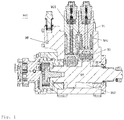
figs. 1 and2 , which schematically show the basic structure of a plunger-type high-pressure pump in the prior art. The plunger-type high-pressure pump 900 comprises ahousing 90; a high-pressureassembly accommodating cavity 901 and acamshaft cavity 902 are provided in thehousing 90, wherein the high-pressureassembly accommodating cavity 901 and thecamshaft cavity 902 are in communication with each other. Acamshaft 92 is disposed in thecamshaft cavity 902; a high-pressure assembly 91 is disposed in the high-pressureassembly accommodating cavity 901. The high-pressure assembly 91 comprises aplunger sleeve 910, and aplunger 911 that is disposed in aplunger cavity 915 of theplunger sleeve 910 and is capable of reciprocating in theplunger cavity 915. A drivenelement 93 is further disposed between the high-pressure assembly 91 and thecamshaft 92; the drivenelement 93 is pushed by a cam on thecamshaft 92, and thereby pushes theabovementioned plunger 911 to reciprocate in theplunger cavity 915. - To prevent lubricating oil in the
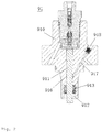
camshaft cavity 902 from entering fuel under the driving action of theplunger 911 and lowering the quality of the fuel, aseal accommodating chamber 912 is provided on a lower side of theplunger sleeve 910; aplunger seal 913 is disposed in theseal accommodating chamber 912, and provides sealing between theplunger 911 and theplunger sleeve 910. Anoil storage groove 916 is disposed at theplunger sleeve 910, above the abovementionedseal accommodating chamber 912; theoil storage groove 916 is used for holding a portion of fuel located between theplunger 913 and theplunger sleeve 910, and guiding same to a fuel tank (not shown in the figures) through anoil drainage channel 917. Theoil drainage channel 917 is a channel drilled from outside theplunger sleeve 910 to theplunger cavity 915; astopper 918 is needed to close theoil drainage channel 917 at one end thereof. - However, since the
plunger seal 913 is generally made of a plastics material, there is a possibility that fragments will form when theplunger 911 rubs against it at high speed, and there is a possibility that fragments will form if the temperature is too high when the oil storage groove 916 rubs against it at high speed; theoil storage groove 916 and theplunger seal 913 are relatively far apart, therefore the cooling effect of fuel on theplunger seal 913 is limited. Furthermore, the presence of the stopper will also result in complex processing steps and components. - The object of the present invention is to provide a plunger-type high-pressure pump, and a high-pressure assembly and plunger sleeve thereof, which are structurally simple and convenient to form by processing.
- The present invention provides a plunger-type high-pressure pump, comprising a pump housing, with a high-pressure assembly accommodating cavity and a camshaft cavity being provided in the pump housing, a high-pressure assembly being disposed in the high-pressure assembly accommodating cavity, a camshaft being disposed in the camshaft cavity, and the camshaft being able to drive the high-pressure assembly, by means of a cam driven apparatus, to perform pressurization, characterized in that the high-pressure assembly comprises a plunger sleeve fixed in the high-pressure assembly accommodating cavity, a plunger that is disposed in a plunger chamber in the plunger sleeve and is capable of reciprocating in the plunger chamber, and a valve assembly disposed in a valve cavity in the plunger sleeve; the plunger chamber is in communication with the valve cavity, a seal accommodating chamber is disposed on the plunger sleeve, a plunger seal is disposed in the seal accommodating chamber, to provide sealing between the plunger and the plunger sleeve, and an oil drainage channel is further disposed on the plunger sleeve, the oil drainage channel having one end in communication with the seal accommodating chamber and another end in communication with the outside of the plunger-type high-pressure pump.
- Preferably, the seal accommodating chamber is in communication with the oil drainage channel via an annular groove or directly.
- Preferably, the other end of the oil drainage channel is in communication with the outside of the plunger-type high-pressure pump via an oil outlet.
- The present invention additionally provides a type of the high-pressure assembly, characterized by comprising a plunger sleeve, a plunger that is disposed in a plunger chamber in the plunger sleeve and is capable of reciprocating in the plunger chamber, and a valve assembly disposed in a valve cavity in the plunger sleeve; the plunger chamber is in communication with the valve cavity, a seal accommodating chamber is disposed on the plunger sleeve, a plunger seal is disposed in the seal accommodating chamber, to provide sealing between the plunger and the plunger sleeve, and an oil drainage channel is further disposed on the plunger sleeve, the oil drainage channel having one end in communication with the seal accommodating chamber and another end in communication with the outside of the high-pressure assembly.
- Preferably, the seal accommodating chamber is in communication with the oil drainage channel via an annular groove or directly.
- Preferably, the other end of the oil drainage channel is in communication with the outside of the high-pressure assembly via an oil outlet.
- The present invention also provides a plunger sleeve of a high-pressure assembly; a seal accommodating chamber housing a plunger seal, and an oil drainage channel, are disposed on the plunger sleeve, the oil drainage channel having one end in communication with the seal accommodating chamber and another end in communication with the outside of the plunger sleeve via an oil outlet.
- Preferably, an extended line of the central axis of the oil drainage channel does not intersect with a bottom end of the plunger sleeve, and the oil drainage channel is in communication with the seal accommodating chamber via an annular groove.
- In the plunger-type high-pressure pump, and high-pressure assembly and plunger sleeve thereof, of the present invention, the oil drainage channel is in communication with a sealing ring accommodating chamber, and is therefore structurally simple and convenient to form by processing.
- Demonstrative embodiments of the present invention will be explained in detail below with reference to the accompanying drawings. It should be understood that the embodiments described below are merely intended to explain the present invention, without limiting the scope thereof. In the accompanying drawings:
-
Fig. 1 is a sectional view of a plunger-type high-pressure pump in the prior art, intended to show the structure and positions of a camshaft and a high-pressure assembly in the high-pressure pump; -
Fig. 2 is a sectional view of a high-pressure assembly of a plunger-type high-pressure pump of the prior art, intended to show the structural design inside the high-pressure assembly, in particular inside a plunger cavity; -
Fig. 3 is a sectional view of an embodiment of the plunger-type high-pressure pump of the present invention, intended to show the positions of the camshaft and high-pressure assembly in the high-pressure pump; -
Fig. 4 is a sectional view of an embodiment of the high-pressure assembly of the plunger-type high-pressure pump of the present invention, intended to show the structural design inside the high-pressure assembly; -
Fig. 5 is a sectional view of an embodiment of the plunger sleeve in the high-pressure assembly of the plunger-type high-pressure pump of the present invention, intended to show the structural design inside the plunger sleeve, in particular inside the plunger cavity. - Identical or similar components in different accompanying drawings are indicated by identical reference labels.
- It should be understood that the accompanying drawings are merely intended to explain the present invention, wherein component sizes, proportional relations and component quantities are not restrictions on the present invention.
- Reference is made to
fig. 3 , which is a schematic structural diagram of an embodiment of a plunger-type high-pressure pump of the present invention. The plunger-type high-pressure pump 100 comprises apump housing 20; a high-pressure assembly 30 and acamshaft 40 disposed in thepump housing 20; and a cam drivenapparatus 50 located between the high-pressure assembly 30 and thecamshaft 40. A high-pressureassembly accommodating cavity 201 and acamshaft cavity 202 are provided in thepump housing 20; the high-pressureassembly accommodating cavity 201 andcamshaft cavity 202 are in communication with each other, and arranged perpendicular to each other. Two high-pressure assembly accommodating cavities are shown infig. 1 ; in other embodiments, other numbers of the high-pressureassembly accommodating cavity 201 are possible. The high-pressure assembly 30 is disposed in the high-pressureassembly accommodating cavity 201, thecamshaft 40 is disposed in thecamshaft cavity 202, and thecamshaft 40 can drive the high-pressure assembly 30, by means of the cam drivenapparatus 50, to perform pressurization. - Referring to
fig. 4 in a coordinated manner, the high-pressure assembly 30 comprises aplunger sleeve 31 fixed in the high-pressureassembly accommodating cavity 201; aplunger cavity 311 and avalve cavity 312 in communication with each other are provided in theplunger sleeve 31. Aplunger 32 is installed in theplunger cavity 311, avalve assembly 33 is disposed in thevalve cavity 312, and a high-pressure cavity is formed between theplunger 32 and thevalve assembly 33, at the top of theplunger cavity 311. Theplunger 32 can reciprocate in theplunger cavity 311 under the driving action of the cam drivenapparatus 50, so as to perform oil suction and oil pressurizing operations. - Referring to
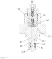
fig. 5 in a coordinated manner, aseal accommodating chamber 314 is formed by processing at the bottom of theplunger seal 31, i.e. in a part close to the cam drivenapparatus 50. Anannular groove 316 is formed at an upper part of theseal accommodating chamber 314, and anoil drainage channel 315 is formed by processing so as to run from theannular groove 316 obliquely upwards into theplunger sleeve 31, such that an extended line of the central axis of theoil drainage channel 315 does not intersect with the bottom end of theplunger sleeve 31. Theoil drainage channel 315 is further connected to anoil outlet 317, so as to discharge drained oil from theannular groove 316. In this embodiment, it will be discharged to a fuel tank, but in other embodiments, it may be discharged to any other place outside theplunger sleeve 31. In this embodiment, the sealaccommodating chamber 314 is connected to theoil drainage channel 315 via theannular groove 316, but in other embodiments, theannular groove 316 could also be omitted, such that theseal accommodating chamber 314 is in direct communication with theoil drainage channel 315. - Referring to
figs. 4 and5 in combination, theplunger 32 is installed in theplunger cavity 311, and aplunger seal 34 is disposed in theseal accommodating chamber 314. When theplunger 32 reciprocates in theplunger cavity 311, high-pressure fuel in the high-pressure cavity will partially drain into a gap between theplunger 32 and theplunger sleeve 31, thereby providing lubrication at this site. Furthermore, fuel that has drained to theseal accommodating chamber 314 can also carry away some of the heat generated by friction between theplunger seal 34 and theplunger 32, and be discharged out of theplunger sleeve 31 through theoil outlet 317. - In the plunger-type high-pressure pump, and high-pressure assembly and plunger sleeve thereof, of the present invention, the oil drainage channel is in communication with a sealing ring accommodating chamber, and is therefore structurally simple and convenient to form by processing. The robustness of the product is improved in two ways at the same time: the distance between the
annular groove 316 and theplunger seal 34 is shortened, enhancing the cooling of theplunger seal 34 by fuel, lowering the operating temperature thereof and thereby reducing the speed of ageing thereof, to increase the lifespan; and enhancing lubrication between theplunger sleeve 31 and theplunger 32 at an upper part of theplunger seal 34, to reduce the risk of seizing. - The present invention is described above merely with reference to the most practical preferred embodiments considered at the present time. It must be understood that the explanation above is not a limitation of the present invention, and the present invention is not limited to the examples given above. Changes, alterations in form, additions or substitutions made by those skilled in the art within the substantive scope of the present invention should also be included in the scope of protection of the present invention.
Claims (11)
- A plunger-type high-pressure pump (100), comprising a pump housing (20), with a high-pressure assembly accommodating cavity (201) and a camshaft cavity (202) being provided in the pump housing (20), a high-pressure assembly (30) being disposed in the high-pressure assembly accommodating cavity (201), a camshaft (40) being disposed in the camshaft cavity (202), and the camshaft (40) being able to drive the high-pressure assembly (30), by means of a cam driven apparatus (50), to perform pressurization, characterized in that the high-pressure assembly (30) comprises a plunger sleeve (31) fixed in the high-pressure assembly accommodating cavity (201), a plunger (32) that is disposed in a plunger chamber (311) in the plunger sleeve (31) and is capable of reciprocating in the plunger chamber (311), and a valve assembly (33) disposed in a valve cavity (312) in the plunger sleeve (31); the plunger chamber (311) is in communication with the valve cavity (312), a seal accommodating chamber (314) is disposed on the plunger sleeve (31), a plunger seal (34) is disposed in the seal accommodating chamber (314), to provide sealing between the plunger (32) and the plunger sleeve (31), and an oil drainage channel (315) is further disposed on the plunger sleeve, the oil drainage channel (315) having one end in communication with the seal accommodating chamber (314) and another end in communication with the outside of the plunger-type high-pressure pump (100).
- The plunger-type high-pressure pump (100) as claimed in Claim 1, characterized in that the seal accommodating chamber (314) is in communication with the oil drainage channel (315) via an annular groove (316).
- The plunger-type high-pressure pump (100) as claimed in Claim 1, characterized in that the seal accommodating chamber (314) is in direct communication with the oil drainage channel (315).
- The plunger-type high-pressure pump (100) as claimed in Claim 2 or 3, characterized in that the other end of the oil drainage channel (315) is in communication with the outside of the plunger-type high-pressure pump (100) via an oil outlet (317).
- A type of the high-pressure assembly (30), characterized by comprising a plunger sleeve (31), a plunger (32) that is disposed in a plunger chamber (311) in the plunger sleeve (31) and is capable of reciprocating in the plunger chamber (311), and a valve assembly (33) disposed in a valve cavity (312) in the plunger sleeve (31); the plunger chamber (311) is in communication with the valve cavity (312), a seal accommodating chamber (314) is disposed on the plunger sleeve (31), a plunger seal (34) is disposed in the seal accommodating chamber (314), to provide sealing between the plunger (32) and the plunger sleeve (31), and an oil drainage channel (315) is further disposed on the plunger sleeve (31), the oil drainage channel (315) having one end in communication with the seal accommodating chamber (314) and another end in communication with the outside of the high-pressure assembly (30).
- The high-pressure assembly (30) as claimed in Claim 5, characterized in that the seal accommodating chamber (314) is in communication with the oil drainage channel (315) via an annular groove (316).
- The high-pressure assembly (30) as claimed in Claim 5, characterized in that the seal accommodating chamber (314) is in direct communication with the oil drainage channel (315).
- The high-pressure assembly (30) as claimed in Claim 6 or 7, characterized in that the other end of the oil drainage channel (315) is in communication with the outside of the high-pressure assembly (30) via an oil outlet (317).
- A plunger sleeve (31) of a high-pressure assembly, characterized in that a seal accommodating chamber (314) housing a plunger seal (34), and an oil drainage channel (315), are disposed on the plunger sleeve (31), the oil drainage channel (315) having one end in communication with the seal accommodating chamber (314) and another end in communication with the outside of the plunger sleeve (31) via an oil outlet (317).
- The plunger sleeve (31) as claimed in Claim 9, characterized in that an extended line of the central axis of the oil drainage channel (315) does not intersect with a bottom end of the plunger sleeve (31).
- The plunger sleeve (31) as claimed in Claim 9, characterized in that the oil drainage channel (315) is in communication with the seal accommodating chamber (314) via an annular groove (316).
Applications Claiming Priority (1)
| Application Number | Priority Date | Filing Date | Title |
|---|---|---|---|
| CN201610884335.3A CN107917028B (en) | 2016-10-10 | 2016-10-10 | Plunger type high-pressure pump and high-pressure assembly and plunger sleeve thereof |
Publications (2)
| Publication Number | Publication Date |
|---|---|
| EP3306071A1 true EP3306071A1 (en) | 2018-04-11 |
| EP3306071B1 EP3306071B1 (en) | 2021-01-06 |
Family
ID=60043034
Family Applications (1)
| Application Number | Title | Priority Date | Filing Date |
|---|---|---|---|
| EP17195118.9A Active EP3306071B1 (en) | 2016-10-10 | 2017-10-06 | Plunger-type high-pressure pump, and high-pressure assembly and plunger sleeve thereof |
Country Status (2)
| Country | Link |
|---|---|
| EP (1) | EP3306071B1 (en) |
| CN (1) | CN107917028B (en) |
Cited By (2)
| Publication number | Priority date | Publication date | Assignee | Title |
|---|---|---|---|---|
| CN108412652A (en) * | 2018-05-07 | 2018-08-17 | 郑国璋 | A kind of diesel engine pluralities of fuel oil spout pump configuration |
| GB2568542A (en) * | 2017-11-21 | 2019-05-22 | Delphi Tech Ip Ltd | High pressure pump with plunger seal protection |
Families Citing this family (1)
| Publication number | Priority date | Publication date | Assignee | Title |
|---|---|---|---|---|
| CN109653921A (en) * | 2018-10-30 | 2019-04-19 | 中国北方发动机研究所(天津) | A kind of injection pump plunger set of anti-plunger clamping stagnation |
Citations (7)
| Publication number | Priority date | Publication date | Assignee | Title |
|---|---|---|---|---|
| DE10322598A1 (en) * | 2003-05-20 | 2004-12-09 | Robert Bosch Gmbh | High-pressure piston pump for internal combustion engine, comprises a holding mechanism, which is radially centered through the cylinder bushing |
| EP1975402A1 (en) * | 2006-01-16 | 2008-10-01 | Nok Corporation | High-pressure fuel pump and seal system for high-pressure fuel pump |
| US20100226795A1 (en) * | 2009-03-05 | 2010-09-09 | Cummins Intellectual Properties, Inc. | High pressure fuel pump with parallel cooling fuel flow |
| WO2012065566A1 (en) * | 2010-11-18 | 2012-05-24 | Robert Bosch Gmbh | High-pressure fuel pump |
| EP2620633A1 (en) * | 2012-01-30 | 2013-07-31 | Delphi Technologies Holding S.à.r.l. | Pump head for a fuel pump |
| WO2015022094A1 (en) * | 2013-08-13 | 2015-02-19 | Continental Automotive Gmbh | High-pressure pump |
| DE102015201444A1 (en) * | 2015-01-28 | 2016-07-28 | Robert Bosch Gmbh | High pressure pump for conveying a medium |
Family Cites Families (3)
| Publication number | Priority date | Publication date | Assignee | Title |
|---|---|---|---|---|
| US9151289B2 (en) * | 2008-08-21 | 2015-10-06 | Cummins Inc. | Fuel pump |
| JP6293994B2 (en) * | 2012-10-31 | 2018-03-14 | 日立オートモティブシステムズ株式会社 | High pressure fuel supply pump |
| DE102014214291A1 (en) * | 2014-07-22 | 2016-01-28 | Robert Bosch Gmbh | High-pressure fuel pump, in particular plug-in pump |
-
2016
- 2016-10-10 CN CN201610884335.3A patent/CN107917028B/en active Active
-
2017
- 2017-10-06 EP EP17195118.9A patent/EP3306071B1/en active Active
Patent Citations (7)
| Publication number | Priority date | Publication date | Assignee | Title |
|---|---|---|---|---|
| DE10322598A1 (en) * | 2003-05-20 | 2004-12-09 | Robert Bosch Gmbh | High-pressure piston pump for internal combustion engine, comprises a holding mechanism, which is radially centered through the cylinder bushing |
| EP1975402A1 (en) * | 2006-01-16 | 2008-10-01 | Nok Corporation | High-pressure fuel pump and seal system for high-pressure fuel pump |
| US20100226795A1 (en) * | 2009-03-05 | 2010-09-09 | Cummins Intellectual Properties, Inc. | High pressure fuel pump with parallel cooling fuel flow |
| WO2012065566A1 (en) * | 2010-11-18 | 2012-05-24 | Robert Bosch Gmbh | High-pressure fuel pump |
| EP2620633A1 (en) * | 2012-01-30 | 2013-07-31 | Delphi Technologies Holding S.à.r.l. | Pump head for a fuel pump |
| WO2015022094A1 (en) * | 2013-08-13 | 2015-02-19 | Continental Automotive Gmbh | High-pressure pump |
| DE102015201444A1 (en) * | 2015-01-28 | 2016-07-28 | Robert Bosch Gmbh | High pressure pump for conveying a medium |
Cited By (3)
| Publication number | Priority date | Publication date | Assignee | Title |
|---|---|---|---|---|
| GB2568542A (en) * | 2017-11-21 | 2019-05-22 | Delphi Tech Ip Ltd | High pressure pump with plunger seal protection |
| CN108412652A (en) * | 2018-05-07 | 2018-08-17 | 郑国璋 | A kind of diesel engine pluralities of fuel oil spout pump configuration |
| CN108412652B (en) * | 2018-05-07 | 2024-01-16 | 梁跃中 | Multi-fuel injection pump structure of diesel engine |
Also Published As
| Publication number | Publication date |
|---|---|
| CN107917028B (en) | 2022-01-18 |
| CN107917028A (en) | 2018-04-17 |
| EP3306071B1 (en) | 2021-01-06 |
Similar Documents
| Publication | Publication Date | Title |
|---|---|---|
| EP3306071A1 (en) | Plunger-type high-pressure pump, and high-pressure assembly and plunger sleeve thereof | |
| ITUD20110007U1 (en) | "ALTERNATIVE PISTON PUMP FOR CRYOGENIC FLUIDS" | |
| JP6553969B2 (en) | Reciprocating compressor | |
| EP2860396A1 (en) | A pump | |
| CN108474337B (en) | High-pressure pump with pump spring sealing sleeve | |
| JP2015505011A (en) | Pump head for fuel pump | |
| KR101683515B1 (en) | Variable compression ratio engine | |
| CN106662062B (en) | High-pressure fuel pump, particularly for the fuel injection device of internal combustion engine | |
| JP6552932B2 (en) | Fuel pump | |
| RU2518796C1 (en) | Machine of positive displacement action | |
| DE50301519D1 (en) | PUMP FOR A HIGH-PRESSURE CLEANER | |
| AU2018256615A1 (en) | Lubricating-grease pump and method for recovery of leakage grease of a lubricating-grease pump | |
| CN110691903B (en) | Fuel pump for supplying fuel to internal combustion piston engine | |
| EP3976967B1 (en) | Variable displacement lubricant pump | |
| KR20150116158A (en) | Mechanical seal for submerged pump | |
| RU2592661C1 (en) | Piston machine operation method and device for its implementation | |
| EP3150842A1 (en) | A high pressure fuel pump | |
| JP5147581B2 (en) | Reciprocating pump | |
| CN110709598B (en) | Fuel pump for supplying fuel to internal combustion piston engine | |
| US1579587A (en) | Double-stroke deep-well pump | |
| CN107322979A (en) | A kind of oil tank of hydraulic machine | |
| KR101658358B1 (en) | Air pressure motors | |
| JP6428361B2 (en) | pump | |
| CN106062353A (en) | High pressure fuel pump | |
| KR20180079526A (en) | Relief valve for oil pump |
Legal Events
| Date | Code | Title | Description |
|---|---|---|---|
| PUAI | Public reference made under article 153(3) epc to a published international application that has entered the european phase |
Free format text: ORIGINAL CODE: 0009012 |
|
| STAA | Information on the status of an ep patent application or granted ep patent |
Free format text: STATUS: THE APPLICATION HAS BEEN PUBLISHED |
|
| AK | Designated contracting states |
Kind code of ref document: A1 Designated state(s): AL AT BE BG CH CY CZ DE DK EE ES FI FR GB GR HR HU IE IS IT LI LT LU LV MC MK MT NL NO PL PT RO RS SE SI SK SM TR |
|
| AX | Request for extension of the european patent |
Extension state: BA ME |
|
| STAA | Information on the status of an ep patent application or granted ep patent |
Free format text: STATUS: REQUEST FOR EXAMINATION WAS MADE |
|
| 17P | Request for examination filed |
Effective date: 20181011 |
|
| RBV | Designated contracting states (corrected) |
Designated state(s): AL AT BE BG CH CY CZ DE DK EE ES FI FR GB GR HR HU IE IS IT LI LT LU LV MC MK MT NL NO PL PT RO RS SE SI SK SM TR |
|
| STAA | Information on the status of an ep patent application or granted ep patent |
Free format text: STATUS: EXAMINATION IS IN PROGRESS |
|
| 17Q | First examination report despatched |
Effective date: 20200131 |
|
| RAP1 | Party data changed (applicant data changed or rights of an application transferred) |
Owner name: ROBERT BOSCH GMBH |
|
| RIC1 | Information provided on ipc code assigned before grant |
Ipc: F04B 53/18 20060101ALI20200806BHEP Ipc: F04B 1/0443 20200101ALI20200806BHEP Ipc: F04B 1/0421 20200101ALI20200806BHEP Ipc: F02M 55/00 20060101AFI20200806BHEP Ipc: F04B 1/0439 20200101ALI20200806BHEP Ipc: F02M 59/44 20060101ALI20200806BHEP Ipc: F02M 59/10 20060101ALI20200806BHEP Ipc: F04B 53/16 20060101ALI20200806BHEP |
|
| GRAP | Despatch of communication of intention to grant a patent |
Free format text: ORIGINAL CODE: EPIDOSNIGR1 |
|
| STAA | Information on the status of an ep patent application or granted ep patent |
Free format text: STATUS: GRANT OF PATENT IS INTENDED |
|
| INTG | Intention to grant announced |
Effective date: 20200929 |
|
| GRAS | Grant fee paid |
Free format text: ORIGINAL CODE: EPIDOSNIGR3 |
|
| GRAA | (expected) grant |
Free format text: ORIGINAL CODE: 0009210 |
|
| STAA | Information on the status of an ep patent application or granted ep patent |
Free format text: STATUS: THE PATENT HAS BEEN GRANTED |
|
| AK | Designated contracting states |
Kind code of ref document: B1 Designated state(s): AL AT BE BG CH CY CZ DE DK EE ES FI FR GB GR HR HU IE IS IT LI LT LU LV MC MK MT NL NO PL PT RO RS SE SI SK SM TR |
|
| REG | Reference to a national code |
Ref country code: GB Ref legal event code: FG4D |
|
| REG | Reference to a national code |
Ref country code: AT Ref legal event code: REF Ref document number: 1352636 Country of ref document: AT Kind code of ref document: T Effective date: 20210115 Ref country code: CH Ref legal event code: EP |
|
| REG | Reference to a national code |
Ref country code: DE Ref legal event code: R096 Ref document number: 602017030816 Country of ref document: DE |
|
| REG | Reference to a national code |
Ref country code: IE Ref legal event code: FG4D |
|
| REG | Reference to a national code |
Ref country code: NL Ref legal event code: MP Effective date: 20210106 |
|
| REG | Reference to a national code |
Ref country code: AT Ref legal event code: MK05 Ref document number: 1352636 Country of ref document: AT Kind code of ref document: T Effective date: 20210106 |
|
| REG | Reference to a national code |
Ref country code: LT Ref legal event code: MG9D |
|
| PG25 | Lapsed in a contracting state [announced via postgrant information from national office to epo] |
Ref country code: BG Free format text: LAPSE BECAUSE OF FAILURE TO SUBMIT A TRANSLATION OF THE DESCRIPTION OR TO PAY THE FEE WITHIN THE PRESCRIBED TIME-LIMIT Effective date: 20210406 Ref country code: LT Free format text: LAPSE BECAUSE OF FAILURE TO SUBMIT A TRANSLATION OF THE DESCRIPTION OR TO PAY THE FEE WITHIN THE PRESCRIBED TIME-LIMIT Effective date: 20210106 Ref country code: NO Free format text: LAPSE BECAUSE OF FAILURE TO SUBMIT A TRANSLATION OF THE DESCRIPTION OR TO PAY THE FEE WITHIN THE PRESCRIBED TIME-LIMIT Effective date: 20210406 Ref country code: PT Free format text: LAPSE BECAUSE OF FAILURE TO SUBMIT A TRANSLATION OF THE DESCRIPTION OR TO PAY THE FEE WITHIN THE PRESCRIBED TIME-LIMIT Effective date: 20210506 Ref country code: FI Free format text: LAPSE BECAUSE OF FAILURE TO SUBMIT A TRANSLATION OF THE DESCRIPTION OR TO PAY THE FEE WITHIN THE PRESCRIBED TIME-LIMIT Effective date: 20210106 Ref country code: GR Free format text: LAPSE BECAUSE OF FAILURE TO SUBMIT A TRANSLATION OF THE DESCRIPTION OR TO PAY THE FEE WITHIN THE PRESCRIBED TIME-LIMIT Effective date: 20210407 Ref country code: HR Free format text: LAPSE BECAUSE OF FAILURE TO SUBMIT A TRANSLATION OF THE DESCRIPTION OR TO PAY THE FEE WITHIN THE PRESCRIBED TIME-LIMIT Effective date: 20210106 |
|
| PG25 | Lapsed in a contracting state [announced via postgrant information from national office to epo] |
Ref country code: PL Free format text: LAPSE BECAUSE OF FAILURE TO SUBMIT A TRANSLATION OF THE DESCRIPTION OR TO PAY THE FEE WITHIN THE PRESCRIBED TIME-LIMIT Effective date: 20210106 Ref country code: LV Free format text: LAPSE BECAUSE OF FAILURE TO SUBMIT A TRANSLATION OF THE DESCRIPTION OR TO PAY THE FEE WITHIN THE PRESCRIBED TIME-LIMIT Effective date: 20210106 Ref country code: AT Free format text: LAPSE BECAUSE OF FAILURE TO SUBMIT A TRANSLATION OF THE DESCRIPTION OR TO PAY THE FEE WITHIN THE PRESCRIBED TIME-LIMIT Effective date: 20210106 Ref country code: SE Free format text: LAPSE BECAUSE OF FAILURE TO SUBMIT A TRANSLATION OF THE DESCRIPTION OR TO PAY THE FEE WITHIN THE PRESCRIBED TIME-LIMIT Effective date: 20210106 |
|
| PG25 | Lapsed in a contracting state [announced via postgrant information from national office to epo] |
Ref country code: IS Free format text: LAPSE BECAUSE OF FAILURE TO SUBMIT A TRANSLATION OF THE DESCRIPTION OR TO PAY THE FEE WITHIN THE PRESCRIBED TIME-LIMIT Effective date: 20210506 |
|
| REG | Reference to a national code |
Ref country code: DE Ref legal event code: R097 Ref document number: 602017030816 Country of ref document: DE |
|
| PG25 | Lapsed in a contracting state [announced via postgrant information from national office to epo] |
Ref country code: SM Free format text: LAPSE BECAUSE OF FAILURE TO SUBMIT A TRANSLATION OF THE DESCRIPTION OR TO PAY THE FEE WITHIN THE PRESCRIBED TIME-LIMIT Effective date: 20210106 Ref country code: EE Free format text: LAPSE BECAUSE OF FAILURE TO SUBMIT A TRANSLATION OF THE DESCRIPTION OR TO PAY THE FEE WITHIN THE PRESCRIBED TIME-LIMIT Effective date: 20210106 |
|
| PLBE | No opposition filed within time limit |
Free format text: ORIGINAL CODE: 0009261 |
|
| STAA | Information on the status of an ep patent application or granted ep patent |
Free format text: STATUS: NO OPPOSITION FILED WITHIN TIME LIMIT |
|
| PG25 | Lapsed in a contracting state [announced via postgrant information from national office to epo] |
Ref country code: DK Free format text: LAPSE BECAUSE OF FAILURE TO SUBMIT A TRANSLATION OF THE DESCRIPTION OR TO PAY THE FEE WITHIN THE PRESCRIBED TIME-LIMIT Effective date: 20210106 Ref country code: RO Free format text: LAPSE BECAUSE OF FAILURE TO SUBMIT A TRANSLATION OF THE DESCRIPTION OR TO PAY THE FEE WITHIN THE PRESCRIBED TIME-LIMIT Effective date: 20210106 Ref country code: SK Free format text: LAPSE BECAUSE OF FAILURE TO SUBMIT A TRANSLATION OF THE DESCRIPTION OR TO PAY THE FEE WITHIN THE PRESCRIBED TIME-LIMIT Effective date: 20210106 |
|
| 26N | No opposition filed |
Effective date: 20211007 |
|
| PG25 | Lapsed in a contracting state [announced via postgrant information from national office to epo] |
Ref country code: AL Free format text: LAPSE BECAUSE OF FAILURE TO SUBMIT A TRANSLATION OF THE DESCRIPTION OR TO PAY THE FEE WITHIN THE PRESCRIBED TIME-LIMIT Effective date: 20210106 Ref country code: ES Free format text: LAPSE BECAUSE OF FAILURE TO SUBMIT A TRANSLATION OF THE DESCRIPTION OR TO PAY THE FEE WITHIN THE PRESCRIBED TIME-LIMIT Effective date: 20210106 |
|
| PG25 | Lapsed in a contracting state [announced via postgrant information from national office to epo] |
Ref country code: SI Free format text: LAPSE BECAUSE OF FAILURE TO SUBMIT A TRANSLATION OF THE DESCRIPTION OR TO PAY THE FEE WITHIN THE PRESCRIBED TIME-LIMIT Effective date: 20210106 |
|
| PG25 | Lapsed in a contracting state [announced via postgrant information from national office to epo] |
Ref country code: IT Free format text: LAPSE BECAUSE OF FAILURE TO SUBMIT A TRANSLATION OF THE DESCRIPTION OR TO PAY THE FEE WITHIN THE PRESCRIBED TIME-LIMIT Effective date: 20210106 |
|
| REG | Reference to a national code |
Ref country code: CH Ref legal event code: PL |
|
| PG25 | Lapsed in a contracting state [announced via postgrant information from national office to epo] |
Ref country code: IS Free format text: LAPSE BECAUSE OF FAILURE TO SUBMIT A TRANSLATION OF THE DESCRIPTION OR TO PAY THE FEE WITHIN THE PRESCRIBED TIME-LIMIT Effective date: 20210506 |
|
| REG | Reference to a national code |
Ref country code: BE Ref legal event code: MM Effective date: 20211031 |
|
| GBPC | Gb: european patent ceased through non-payment of renewal fee |
Effective date: 20211006 |
|
| PG25 | Lapsed in a contracting state [announced via postgrant information from national office to epo] |
Ref country code: MC Free format text: LAPSE BECAUSE OF FAILURE TO SUBMIT A TRANSLATION OF THE DESCRIPTION OR TO PAY THE FEE WITHIN THE PRESCRIBED TIME-LIMIT Effective date: 20210106 |
|
| PG25 | Lapsed in a contracting state [announced via postgrant information from national office to epo] |
Ref country code: LU Free format text: LAPSE BECAUSE OF NON-PAYMENT OF DUE FEES Effective date: 20211006 Ref country code: GB Free format text: LAPSE BECAUSE OF NON-PAYMENT OF DUE FEES Effective date: 20211006 Ref country code: BE Free format text: LAPSE BECAUSE OF NON-PAYMENT OF DUE FEES Effective date: 20211031 |
|
| PG25 | Lapsed in a contracting state [announced via postgrant information from national office to epo] |
Ref country code: LI Free format text: LAPSE BECAUSE OF NON-PAYMENT OF DUE FEES Effective date: 20211031 Ref country code: CH Free format text: LAPSE BECAUSE OF NON-PAYMENT OF DUE FEES Effective date: 20211031 |
|
| PG25 | Lapsed in a contracting state [announced via postgrant information from national office to epo] |
Ref country code: IE Free format text: LAPSE BECAUSE OF NON-PAYMENT OF DUE FEES Effective date: 20211006 |
|
| PGFP | Annual fee paid to national office [announced via postgrant information from national office to epo] |
Ref country code: DE Payment date: 20221215 Year of fee payment: 6 |
|
| PG25 | Lapsed in a contracting state [announced via postgrant information from national office to epo] |
Ref country code: RS Free format text: LAPSE BECAUSE OF FAILURE TO SUBMIT A TRANSLATION OF THE DESCRIPTION OR TO PAY THE FEE WITHIN THE PRESCRIBED TIME-LIMIT Effective date: 20210106 Ref country code: HU Free format text: LAPSE BECAUSE OF FAILURE TO SUBMIT A TRANSLATION OF THE DESCRIPTION OR TO PAY THE FEE WITHIN THE PRESCRIBED TIME-LIMIT; INVALID AB INITIO Effective date: 20171006 |
|
| PG25 | Lapsed in a contracting state [announced via postgrant information from national office to epo] |
Ref country code: NL Free format text: LAPSE BECAUSE OF NON-PAYMENT OF DUE FEES Effective date: 20210206 Ref country code: CY Free format text: LAPSE BECAUSE OF FAILURE TO SUBMIT A TRANSLATION OF THE DESCRIPTION OR TO PAY THE FEE WITHIN THE PRESCRIBED TIME-LIMIT Effective date: 20210106 |
|
| PGFP | Annual fee paid to national office [announced via postgrant information from national office to epo] |
Ref country code: CZ Payment date: 20230926 Year of fee payment: 7 |
|
| PGFP | Annual fee paid to national office [announced via postgrant information from national office to epo] |
Ref country code: FR Payment date: 20231023 Year of fee payment: 7 |