EP3305694B1 - Film supplying device in horizontal package making and filling machine - Google Patents
Film supplying device in horizontal package making and filling machine Download PDFInfo
- Publication number
- EP3305694B1 EP3305694B1 EP17194123.0A EP17194123A EP3305694B1 EP 3305694 B1 EP3305694 B1 EP 3305694B1 EP 17194123 A EP17194123 A EP 17194123A EP 3305694 B1 EP3305694 B1 EP 3305694B1
- Authority
- EP
- European Patent Office
- Prior art keywords
- film
- side rotation
- rotation member
- roll
- support
- Prior art date
- Legal status (The legal status is an assumption and is not a legal conclusion. Google has not performed a legal analysis and makes no representation as to the accuracy of the status listed.)
- Active
Links
- 238000013459 approach Methods 0.000 claims description 3
- 230000007246 mechanism Effects 0.000 description 9
- 238000004806 packaging method and process Methods 0.000 description 5
- 238000004519 manufacturing process Methods 0.000 description 4
- 230000002093 peripheral effect Effects 0.000 description 3
- 230000003014 reinforcing effect Effects 0.000 description 3
- 230000008878 coupling Effects 0.000 description 2
- 238000010168 coupling process Methods 0.000 description 2
- 238000005859 coupling reaction Methods 0.000 description 2
- 239000000463 material Substances 0.000 description 2
- 238000012986 modification Methods 0.000 description 2
- 230000004048 modification Effects 0.000 description 2
- 230000009471 action Effects 0.000 description 1
- 210000000078 claw Anatomy 0.000 description 1
- 230000001419 dependent effect Effects 0.000 description 1
- 238000001514 detection method Methods 0.000 description 1
- 238000011161 development Methods 0.000 description 1
- 230000018109 developmental process Effects 0.000 description 1
- 230000000694 effects Effects 0.000 description 1
- 239000002184 metal Substances 0.000 description 1
- 238000000034 method Methods 0.000 description 1
- 230000003287 optical effect Effects 0.000 description 1
- 238000012545 processing Methods 0.000 description 1
- 230000004044 response Effects 0.000 description 1
- 238000011144 upstream manufacturing Methods 0.000 description 1
- 238000004804 winding Methods 0.000 description 1
Images


Classifications
-
- B—PERFORMING OPERATIONS; TRANSPORTING
- B65—CONVEYING; PACKING; STORING; HANDLING THIN OR FILAMENTARY MATERIAL
- B65H—HANDLING THIN OR FILAMENTARY MATERIAL, e.g. SHEETS, WEBS, CABLES
- B65H20/00—Advancing webs
- B65H20/02—Advancing webs by friction roller
-
- B—PERFORMING OPERATIONS; TRANSPORTING
- B65—CONVEYING; PACKING; STORING; HANDLING THIN OR FILAMENTARY MATERIAL
- B65B—MACHINES, APPARATUS OR DEVICES FOR, OR METHODS OF, PACKAGING ARTICLES OR MATERIALS; UNPACKING
- B65B35/00—Supplying, feeding, arranging or orientating articles to be packaged
- B65B35/10—Feeding, e.g. conveying, single articles
- B65B35/24—Feeding, e.g. conveying, single articles by endless belts or chains
-
- B—PERFORMING OPERATIONS; TRANSPORTING
- B65—CONVEYING; PACKING; STORING; HANDLING THIN OR FILAMENTARY MATERIAL
- B65B—MACHINES, APPARATUS OR DEVICES FOR, OR METHODS OF, PACKAGING ARTICLES OR MATERIALS; UNPACKING
- B65B41/00—Supplying or feeding container-forming sheets or wrapping material
- B65B41/12—Feeding webs from rolls
- B65B41/16—Feeding webs from rolls by rollers
-
- B—PERFORMING OPERATIONS; TRANSPORTING
- B65—CONVEYING; PACKING; STORING; HANDLING THIN OR FILAMENTARY MATERIAL
- B65B—MACHINES, APPARATUS OR DEVICES FOR, OR METHODS OF, PACKAGING ARTICLES OR MATERIALS; UNPACKING
- B65B9/00—Enclosing successive articles, or quantities of material, e.g. liquids or semiliquids, in flat, folded, or tubular webs of flexible sheet material; Subdividing filled flexible tubes to form packages
- B65B9/06—Enclosing successive articles, or quantities of material, in a longitudinally-folded web, or in a web folded into a tube about the articles or quantities of material placed upon it
-
- B—PERFORMING OPERATIONS; TRANSPORTING
- B65—CONVEYING; PACKING; STORING; HANDLING THIN OR FILAMENTARY MATERIAL
- B65H—HANDLING THIN OR FILAMENTARY MATERIAL, e.g. SHEETS, WEBS, CABLES
- B65H2301/00—Handling processes for sheets or webs
- B65H2301/50—Auxiliary process performed during handling process
- B65H2301/51—Modifying a characteristic of handled material
- B65H2301/512—Changing form of handled material
- B65H2301/5121—Bending, buckling, curling, bringing a curvature
- B65H2301/51214—Bending, buckling, curling, bringing a curvature parallel to direction of displacement of handled material
- B65H2301/512145—Forming a tube
-
- B—PERFORMING OPERATIONS; TRANSPORTING
- B65—CONVEYING; PACKING; STORING; HANDLING THIN OR FILAMENTARY MATERIAL
- B65H—HANDLING THIN OR FILAMENTARY MATERIAL, e.g. SHEETS, WEBS, CABLES
- B65H2301/00—Handling processes for sheets or webs
- B65H2301/50—Auxiliary process performed during handling process
- B65H2301/52—Auxiliary process performed during handling process for starting
- B65H2301/522—Threading web into machine
-
- B—PERFORMING OPERATIONS; TRANSPORTING
- B65—CONVEYING; PACKING; STORING; HANDLING THIN OR FILAMENTARY MATERIAL
- B65H—HANDLING THIN OR FILAMENTARY MATERIAL, e.g. SHEETS, WEBS, CABLES
- B65H2404/00—Parts for transporting or guiding the handled material
- B65H2404/10—Rollers
- B65H2404/14—Roller pairs
- B65H2404/143—Roller pairs driving roller and idler roller arrangement
-
- B—PERFORMING OPERATIONS; TRANSPORTING
- B65—CONVEYING; PACKING; STORING; HANDLING THIN OR FILAMENTARY MATERIAL
- B65H—HANDLING THIN OR FILAMENTARY MATERIAL, e.g. SHEETS, WEBS, CABLES
- B65H2404/00—Parts for transporting or guiding the handled material
- B65H2404/10—Rollers
- B65H2404/14—Roller pairs
- B65H2404/144—Roller pairs with relative movement of the rollers to / from each other
-
- B—PERFORMING OPERATIONS; TRANSPORTING
- B65—CONVEYING; PACKING; STORING; HANDLING THIN OR FILAMENTARY MATERIAL
- B65H—HANDLING THIN OR FILAMENTARY MATERIAL, e.g. SHEETS, WEBS, CABLES
- B65H2701/00—Handled material; Storage means
- B65H2701/10—Handled articles or webs
- B65H2701/17—Nature of material
- B65H2701/175—Plastic
- B65H2701/1752—Polymer film
-
- B—PERFORMING OPERATIONS; TRANSPORTING
- B65—CONVEYING; PACKING; STORING; HANDLING THIN OR FILAMENTARY MATERIAL
- B65H—HANDLING THIN OR FILAMENTARY MATERIAL, e.g. SHEETS, WEBS, CABLES
- B65H2801/00—Application field
- B65H2801/69—Form fill-and-seal machines
Description
- The present invention relates to a film supplying device for a horizontal package making and filling machine, which includes a pair of rolls for drawing a film from a film roll.
- A horizontal package making and filling machine has been widely put to practical use that, while feeding a belt-like film (hereinafter referred to as film), overlaps widthwise both end edges of the film with each other to form a tubular shape, and applies a longitudinal seal to the overlapped part along the feeding direction of the tubular film, and applies lateral seals to the film at the front and rear of articles, filled in the tubular film at predetermined intervals, along a direction crossing the feeding direction of the tubular film. A known way of this horizontal package making and filling machine includes a feed roll composed of a drive roll and a driven roll, which is provided in a film feed course between the film roll and a package former, and draws a film from the film roll by way of the feed roll (for example, refer to
JP 3721534 B2 -
US 2015/259168 A1 further discloses methods and systems for processing films in packaging machines according to the preamble of claim 1. - The feed roll disclosed in
JP 3721534 B2 - As the open-and-close mechanism, an eccentric mechanism is adopted in which a shaft on which a driven roll is rotatably supported is rotatably provided on both frames via an eccentric holder to which the shaft is eccentrically connected, and an operation lever provided on the eccentric holder is turned to eccentrically move the shaft to thereby separate the driven roll from the drive roll. The film setting operation is carried out by the operator by separating both rolls to pass the leading end of the film through openings (holes) formed by both rolls and both frames, and then setting the film on a guide roll, a package former, or the like provided downstream of the openings in the film feed course.
- In such a film setting operation, an operation of drawing the film from the heavy film roll requires a large force. In addition, since the width by which both rolls can be separated by the eccentric mechanism is narrow, the film is drawn out by a slightly excess amount from the roll beforehand, and the leading end of the film is passed through the narrow openings to avoid simultaneous execution of an operation requiring delicacy and an operation requiring force. However, an operator who is unfamiliar with such a setting operation may draw the film too much in the film setting operation, and have a trouble in handling the film when passing the leading end of the film through the narrow openings. Also, care should be taken not to damage the film that is drawn out much, thus lowering the operating efficiency. That is, the time required for the film setting operation varies depending on the skills of the operators, which may interfere with the efficient production.
- The present invention has been made and proposed in consideration of, and to solve, the above-mentioned problems of the related art, and provides a film supplying device in a horizontal package making and filling machine that can increase the efficiency of an operation of setting a film.
- The above mentioned problem is solved and the desired purpose is achieved by a film supplying device for a horizontal package making and filling machine according to a first aspect of the invention set forth in claim 1. Further developments of the present invention are described in dependent claims.
- According to the first aspect of the invention set forth in claim 1 , the second support member that supports the drive side rotation member is configured to be movable between the sandwiched position in which the driven side rotation member approaches the drive side rotation member supported on the first support member, and the retract position spaced apart therefrom, so that the driven side rotation member and the drive side rotation member may be greatly spaced apart from each other to facilitate a film setting operation.
- That is, it is possible to eliminate a troublesome delicate operation of passing the leading end of the film through a narrow opening, which may improve the operability of setting the film, and prevent the production efficiency from varying depending on the skills of the operators. In addition, the drive side rotation member is configured to be supported on the first support member fixed to the main body, so that the structure of coupling the drive system to the drive side rotation member may be simplified.
- According to the second aspect of the invention set forth in claim 2, the second support member is configured to be horizontally movable, so that the operator need not hold the second support member moved to the retract position, ensuring a proper operability.
- According to the third aspect of the invention set forth in claim 3, the cover that covers the upper side of the facing region of the drive side rotation member and the driven side rotation member in the sandwiched position is provided in the second support member, making it possible to prevent a foreign matter or the like from entering the facing region during a packaging operation. In addition, since the cover is also separated from the upper side of the facing region by moving the second support member at the time of setting the film, the cover does not interfere with the film setting operation to smoothly proceed with the film setting operation.
- According to the fourth aspect of the invention set forth in claim 4, even when an operator releases hands with the film wound on the drive side rotation member during the film setting operation, the film does not come off the drive side rotation member, resulting in an improved operability.
- The film supplying device for a horizontal package making and filling machine according to the present invention may enhance the operability of the film setting operation to improve the production efficiency.
-
- [
FIG. 1 ] A schematic side view illustrating a horizontal package making and filling machine using a film supplying device according to an embodiment of the invention. - [
FIG. 2 ] A schematic perspective view illustrating a state where a second support in the film supplying device according to the embodiment is moved to a retract position. - [
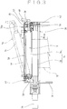
FIG. 3 ] A schematic cross-sectional view taken along line A-A inFIG. 1 of the film supplying device according to the embodiment. - [
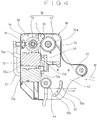
FIG. 4 ] A schematic cross-sectional view taken along line B-B inFIG. 3 of the film supplying device according to the embodiment. - Next, a film supplying device for a horizontal package making and filling machine according to the invention is described with reference to the accompanying drawings by raising the preferred embodiment.
-
FIG. 1 illustrates a horizontal package making and filling machine provided with a film supplying device according to an embodiment. The horizontal package making and filling machine includes tube former 14 for overlapping both widthwise end edges of afilm 12, drawn from afilm roll 10, in a folded shape to form atubular film 12a, asupply conveyor 18 for supplyingarticles 16 toward thetubular film 12a at predetermined intervals,longitudinal seal device 20 for applying a longitudinal seal to the overlapped portion of thetubular film 12a overlapped in the folded shape,film conveying device 22 for holding the overlapped portion of thetubular film 12a, and conveying thetubular film 12a toward thelongitudinal seal device 20, andlateral seal device 24 for holding thetubular film 12a at the front and rear positions of thearticles 16 supplied inside thetubular film 12a, and applying a lateral seal to thetubular film 12a in a direction crossing the conveying direction of thetubular film 12a. The horizontal package making and filling machine also includes approachingangle adjusting device 49 for adjusting the approaching angle of thefilm 12 directed toward the tube former 14 in the film feed course between thefilm roll 10 and the tube former 14, and has a film supplying device provided in the film feed course between thefilm roll 10 and the approachingangle adjusting device 49 for feeding thefilm 12, drawn from thefilm roll 10, toward the tube former 14. - The
supply conveyor 18, the tube former 14, and the like are disposed on the front side of a main frame 26 (part of which is shown inFIGs. 1 and2 ) constituting the frame of the horizontal package making and filling machine, where an operator performs a drive operation, a film setting operation, and so forth. A plurality of (two in the embodiment)loading shafts 28 to which thefilm roll 10 is rotatably loaded are cantilever-supported on themain frame 26 so as to extend horizontally toward the front side above the supply conveyor 18 (seeFIG. 2 ). Further, the film supplying device and the approachingangle adjusting device 49 are disposed on themain frame 26 at positions spaced apart rightward from theloading shaft 28 located on the right side (the side approaching the lateral seal device 24) inFIG. 1 , and between thefilm roll 10 and the tube former 14 at the height position. As shown inFIG. 3 , the film supplying device includes afeed roll 36 composed of adrive roll 32 as drive side rotation member, which is rotated by adrive motor 30 such as a servomotor, and a drivenroll 34 as driven side rotation member, which may hold thefilm 12 with thedrive roll 32, and also includes afirst support 38 and asecond support 56. While the surface of thedrive roll 32 is metal, the drivenroll 34 is composed of a rubber roll whose surface is made of a rubber material. With thefilm 12 being sandwiched between thedrive roll 32 extending along the width direction of thefilm 12 and the drivenroll 34 moved to a sandwiched position to be described later, the drivenroll 34 is driven responsive to the rotation of thedrive roll 32 to draw out thefilm 12 from thefilm roll 10 and deliver thefilm 12 downstream. - The first support (first support member) 38 includes a
fixed panel 31 fixed to themain frame 26, a reinforcing stay 40 (seeFIG. 4 ) extending frontward along the axis of thedrive roll 32 rotatably supported by thefixed panel 31, and asub frame 42 connected to the extending end of thereinforcing stay 40. Thedrive roll 32 has one end directed to the back side and inserted into a hole formed in thefixed panel 31 to be drivingly connected to adrive motor 30 such as a servo motor fixed to the back surface of thefixed panel 31. The other end of thedrive roll 32 is rotatably supported by thefirst support 38 fixed to thefixed panel 31 at a position spaced apart frontward from the fixedpanel 31. That is, thedrive roll 32 is rotatebly supported on both sides in the rotational axial direction so that its rotational axis extends along the horizontal direction with respect to thefirst support 38. Thus, thedrive roll 32 is kept parallel to theloading shaft 28 cantilever-supported by themain frame 26. That is, thedrive roll 32 is supported by themain frame 26 so as to extend in an orthogonal direction to the film drawing direction (the width direction of the film in the intersecting direction). As separate from thedrive roll 32,guide rolls first support 38 and can guide winding of thefilm 12, are disposed between the fixedpanel 31 and thesub frame 42 so as to be parallel to thedrive roll 32 as shown inFIG. 1 . - The four
guide rolls guide rolls panel 31 and thesub frame 42, and twoguide rolls panel 31 and thesub frame 42 and are rotatably supported by a pair ofswing arms 48, 48 (only one is shown inFIGs. 1 and2 ) spaced apart in the axial direction of thedrive roll 32. Theguide roll 45 is disposed on the upstream side of thedrive roll 32 in the film feed course, and theguide roll 44 is located just below thedrive roll 32 and spaced apart therefrom. That is, thefilm 12 drawn from thefilm roll 10 is wound on theguide roll 45 through aguide roll 19 disposed on themain frame 26 so as to extend frontward from themain frame 26, and is then guided to thedrive roll 32 from the side (more specifically, from obliquely below the left side), and is wound on the outer peripheral surface of thedrive roll 32 from the upper side. Then, thefilm 12 passed through thedrive roll 32 is fed out just under so that the film feeding direction becomes the upward and downward direction to be wound on theguide roll 44. Theguide roll 19 is provided at such a position that even if thefilm 12 is drawn out from any of thefilm rolls film rolls loading shafts film 12 can be guided to be wound on theguide roll 19. Then, the position of theguide roll 45 in the film supplying device is set in such a way that thefilm 12 can be guided to be wounded on theguide roll 45 at a height position where interference between thefilm 12 fed from theguide roll 19 and thefilm roll 10 on the right side inFIG. 1 can be avoided. - One ends of the
swing arms guide roll 44. Thesub frame 42 is provided with a locating member 50 (seeFIG. 4 ) in which a plurality of locatingslots 50a are provided in a circumferential direction of a circle centered on the rotation center of theswing arm 48. Further, an engaging portion (not shown) which is detachably engaged with the locatingslot 50a is provided on theswing arm 48 on the sub frame side, and changing the position of the locatingslot 50a engaged with the engaging portion changes the inclination angle of the pair ofswing arms guide rolls swing arms like film 12 passed through thedownstream guide roll 44 is wound on the twoguide rolls guide rolls swing arms operation handle 52, which is disposed in thesub frame 42 and coupled to the ball screw mechanism, is operated to actuate the ball screw mechanism, the guide rolls 46, 46 can be moved and adjusted in the longitudinal direction of theswing arms angle adjusting device 49. Changing the angle of theswing arms swing arms film 12 approaching the tube former 14 from the guide rolls (approaching angle adjusting roll) 46 located immediately before the tube former 14 according to the sizes of thearticles 16 or the like. - An arm locking member (not shown) capable of switching between a lockable state and an unlocked state is provided on the
first support 38 with the engaging portion of theswing arm 48 being engaged with the locatingslot 50a of the locatingmember 50 in response to the forward/reverse rotational operation of anoperation lever 53. The arm locking member is configured in such a way that with the arm locking member being unlocked, as theswing arms slot 50a, and selective switching operation to engage with an anotherlocating slot 50a is enabled. The locked state that is set by the arm locking member enhances further the rigidity of thefirst support 38. As shown inFIGs. 2 and4 , thefirst support 38 is provided with afirst cover 54 having anotch 54a so as to expose the upper outer peripheral surface of thedrive roll 32, so that thefirst cover 54 does not contact the belt-like film 12 moving in the film feed course extending from theguide roll 45 to thedrive roll 32. Thefirst cover 54 is also formed so as not to contact or interfere with thefilm 12 moving along the film feed course extending from theguide roll 44 to theguide roll 46. - As shown by a solid line in
FIG. 3 , the second support (second support member) 56 includes a pair ofside walls outer wall 60 disposed between theside walls first support 38 is formed in a box shape whose side facing thefirst support 38 is dented. The rotational shaft of the drivenroll 34 extends in the horizontal direction and is rotatably supported by theside walls second support 56 is supported, byhinges 61 disposed above and below with respect to the fixedpanel 31, so as to be rotatable about a single vertical axis extending in the vertical direction. As a result, thesecond support 56 rotates along the horizontal plane with thehinges 61 serving as a fulcrum, so that the front side of thesecond support 56 can open and close with respect to thefirst support 38. As a result, thesecond support 56 can horizontally rotate between the sandwiched position (the solid line position inFIG. 3 ) where the drivenroll 34 may approach thedrive roll 32 so as to be aligned in the horizontal direction and may hold thefilm 12, and the retract position (the position indicated by a two-dot chain line inFIG. 3 ) in which the drivenroll 34 is spaced laterally from thedrive roll 32. It should be noted that thesecond support 56 can rotate substantially 90 degrees at which the drivenroll 34 is separated from thedrive roll 32 with reference to the sandwiched position. Thesecond support 56 is supported by the fixedpanel 31 on the side opposite to the side where thefilm 12 is guided to thedrive roll 32 via theguide roll 45 with respect to thefirst support 38. - A second cover (a cover) 66 is provided on the
second support 56 so as to cover thedrive roll 32, which is exposed upward from thenotch 54a of thefirst cover 54, from the upper side in the sandwiched position. That is, as shown inFIG. 4 , thesecond cover 66 is configured to cover the upper side of the facing region S where the drivenroll 34 and thedrive roll 32 face each other in the sandwiched position to prevent entry of a foreign matter other than the film from the outside. Further, anoperation handle 57 is provided on thesecond support 56 at the front-side end portion. - The driven
roll 34 is rotatably disposed with respect to a support shaft (a rotational shaft) 35 supported between bothside walls support shaft 35 is rotated by theoperation lever 68, the drivenroll 34 moves away from thedrive roll 32 in the sandwiched position by way of the action of the eccentric mechanism, so that thefilm 12 can be free from the pinching force applied by bothrolls -
Support locking member 70 which engage with each other to keep thesecond support 56 in the sandwiched position are respectively provided on thesub frame 42 of thefirst support 38 and the front-side side wall 58 of thesecond support 56. Thesupport locking member 70 is configured in such a way that the locked state may be released by operating an unlockinglever 70a disposed on thesecond support 56. As long as the unlockinglever 70a is not operated, the locking state of thesecond support 56 with respect to thefirst support 38 is maintained by thesupport locking member 70. Further, thesupport locking member 70 is configured so that when thesecond support 56 is rotated to the sandwiched position, thefirst support 38 and thesecond support 56 are automatically locked by a claw (not shown) energized by a spring. - As shown in
FIG. 4 , opticaltype sensor units 72 including a CIS (Contact Image Sensor) that scans a pattern, a bar code or the like printed at regular intervals on thefilm 12 are disposed directly below thefeed roll 36 on both sides in the film feed course. Thesensor unit 72 includes amain body 72a disposed on thefirst support 38 and areflector 72b disposed on thesecond support 56 so as to face themain body 72a, so that the pattern, the bar code or the like can be detected based on the light receiving state from thereflector 72b of the light irradiated from themain body 72a. Thesensor unit 72 is configured so that its length is set longer than the length of thefeed roll 36 in the width direction, and the pattern or the like across the entire width of thefilm 12 can be detected. In the embodiment, the entire width of thefilm 12 can be detected by shifting and arranging two pairs ofmain bodies 72a andreflectors 72b in the lateral direction so that a part of the detection region overlaps. - Next, the operation of the film supplying device according to the embodiment is described. To set the
film 12 in the horizontal package making and filling machine, with thesupport locking member 70 being unlocked, holding thehandle 57 provided on the front side of thesecond support 56, thesecond support 56 is horizontally rotated about thehinges 61 as a fulcrum. As a result, the drivenroll 34 is separated laterally from the drive roll 32 (seeFIG. 2 ). Then, after the belt-like film 12, drawn out from thefilm roll 10, is wound on theguide roll 45, the belt-like film 12 is wound on the outer peripheral surface of thedrive roll 32 exposed from thenotch 54a of thefirst cover 54 from the side. Next, after thefilm 12 wound on thedrive roll 32 is wound on theguide roll 44, thefilm 12 is wound on the two guide rolls 46, 46 and set so as to reach the tube former 14 and thelongitudinal seal device 20. - When the
second support 56 is rotated to the sandwiched position after the operation of setting thefilm 12 is completed, thefilm 12 wound on thedrive roll 32 is pinched by thedrive roll 32 and the drivenroll 34. In addition, thesupport locking member 70 locks thesecond support 56 to thefirst support 38 to keep thesecond support 56 in the sandwiched position. With the above operation being completed, when thedrive roll 32 is rotated by thedrive motor 30, thefilm 12 drawn from thefilm roll 10 and guided from the side to thedrive roll 32 is fed downward from the sandwiched position of bothrolls feed roll 36. - Since the film supplying device in the embodiment is configured so that the
second support 56 can be horizontally rotated about thehinge 61 provided at the back-side end portion of thesecond support 56, the front side of the drivenroll 34 may be largely separated from thedrive roll 32, thus facilitating the operation of passing thefilm 12 between therolls film 12 from thefilm roll 10 to a greater extent, the drivenroll 34 can be greatly separated from thedrive roll 32, so that thefilm 12 may be easily passed through the space between therolls second support 56 is cantilever-supported with respect to themain frame 26, there is not any member that interferes with the operation on the front side of thesecond support 56 moved to the retract position, and the wearing state of the drivenroll 34 made of a rubber material may be easily viewed from the front side. Furthermore, since thefirst support 38 for supporting thedrive roll 32 is fixed and thesecond support 56 for supporting the drivenroll 34 is configured to be movable, it is possible to simplify the coupling structure of thedrive roll 32 to thedrive motor 30 or the like. In addition, disposing thedrive motor 30 on the side of the fixedfirst support 38 may make it easy to suppress the generation of a vibration and noise which generate when thedrive motor 30 is driven. - Further, the
film 12 is guided to thedrive roll 32 from the side opposite to the side on which the drivenroll 34 is disposed, and is wound on thedrive roll 32, and then is fed downward, and the facing region S where thedrive roll 32 and the drivenroll 34 sandwich thefilm 12 is covered from the upper side by thesecond cover 66 provided on thesecond support 56, so that it is possible to prevent a foreign matter from being caught in the facing region S during the packaging operation, thus preventing the occurrence of a packaging failure or the like caused by the entry of a foreign matter. Further, since thesecond cover 66 covering the facing region S of bothrolls second support 56, thesecond cover 66 is separated, together with thesecond support 56, sideward from the upper side of thedrive roll 32. Therefore, the film setting operation is not hindered by thesecond cover 66, and a proper operability may be guaranteed. - The
second support 56 is configured to be rotated in the horizontal direction, so that the operator does not need to support thesecond support 56 and can easily move thesecond support 56 with one hand. Since it is unnecessary to hold thesecond support 56 not to move thesecond support 56 after the movement of thesecond support 56 is complete, both hands of the operator are free so that the film setting operation can be easily performed. Further, if thefilm 12 drawn from thefilm roll 10 is wound on thedrive roll 32 from the upper side, thefilm 12 may not come off thedrive roll 32 even if the grip of the hands on thefilm 12 is released. This allows the operator to set both hands free to increase operability. Theguide roll 45 for guiding thefilm 12 guided from theguide roll 19 provided at the intermediate position between the two film rolls 10 so as not to interfere with the film rolls 10 is rotatably supported by the fixedpanel 31 and thesub frame 42, so that the rigidity of the film supplying device may be enhanced (strengthened), leading to simplification of the configuration. Furthermore, at a height position (between thefilm roll 10 and the tube former 14) where thefilm 12 guided from theguide roll 45 does not interfere with the film feed course between theguide roll 19 and theguide roll 45 by setting the approachingangle adjusting device 49 between the fixedpanel 31 and thesub frame 42 so as to adjust the position of the approachingangle adjusting roll 46 according to the kind of the packaged product or the like, the rigidity can be increased, thereby simplifying the configuration. - The present invention is not limited to the configuration of the embodiment, and may be modified, for example, as follows. In addition, the present invention is not limited to the following modifications, and various configurations may be adopted for the configurations described with reference to the embodiment within the scope and spirit of the subject matter of the invention.
- (1) Although the
second support 56 is configured to be supported by the fixedpanel 31 of themain frame 26 by thehinge 61, thesecond support 56 may be directly supported on themain frame 26 or thesecond support 56 may be rotatably supported on thefirst support 38 fixed to themain frame 26. That is, it is possible to adopt various support structures for supporting thesecond support 56 to themain frame 26 directly, or indirectly via a separate member. - (2) It is possible to adopt such a configuration that instead of the
hinge 61, a rail or the like may be used to movably support thesecond support 56 to the fixedpanel 31 or themain frame 26 so that as the drivenroll 34 is moved closer to or away from thedrive roll 32, the one end side (front side) of thefeed roll 36 which intersects the film drawing direction is widely opened. - (3) The configuration may be adapted to the configuration that feeds the
film 12 from the lower side of thefeed roll 36 to the upper side. - (4) The
support locking member 70 that keeps thesecond support 56 in the sandwiched position may be configured to lock thesecond support 56 with respect to themain frame 26. - (5) The driven
roll 34 is not limited to the configuration in which the drivenroll 34 rotates with respect to thesupport shaft 35, but the support shaft integrally provided with the drivenroll 34 may be rotatably supported with respect to thesecond support 56 so that the drivenroll 34 may rotate together with the support shaft. - (6) The first support (first support member) 38 may take a configuration in which the
drive roll 32 may be rotatably supported between a pair of side walls provided at both ends of the reinforcingstay 40, with one side wall being fixed to themain frame 26, instead of the configuration of supporting one axial end of thedrive roll 32 with themain frame 26. - (7) The supply conveyor is not indispensable as a horizontal package making and filling machine.
- (8) The configuration may be applied to a horizontal package making and filling machine that forms the overlapped portion of both ends of the
film 12, fed to the tube former 14 from a position lower than the tube former 14, on the upper portion of the tubular film, or a film supplying device of a horizontal package making and filling machine that forms the overlapped portion on a side portion of the tubular film. The horizontal package making and filling machine in which the overlapped portion is formed on the side portion of the tubular film may take a configuration in which the entire structure shown inFIG. 2 including the film supplying device is rotated 90 degrees so that the free end side of theloading shaft 28 faces upward. Further, it is possible to adopt a configuration in which the entire structure ofFIG. 2 except the approachingangle adjusting device 49 is rotated by 90 degrees. That is, the drive roll (drive side rotation member) and the driven roll (driven side rotation member) of the film supplying device may take any configuration as long as the driven roll (driven side rotation member) may be aligned with the side of the drive roll (drive side rotation member) to be able to pinch the film in the sandwiched position, and the driven roll (driven side rotation member) may be separated from the drive roll (drive side rotation member) in the retract position. - (9) It is possible to adopt such a configuration that the
film 12 may be sandwiched by a pair of belts (drive side and driven side rotation member) or the like, which are driven to run, instead of thedrive roll 32 and the drivenroll 34, to draw thefilm 12 from thefilm roll 10. - (10) The approaching
angle adjusting device 49 is not limited to the configuration in which the approachingangle adjusting device 49 is provided on the first support 38 (film supplying device), and may take a configuration in which the approachingangle adjusting device 49 is separately provided on themain frame 26 or the like on the downstream side of the film supplying device. -
- 10
- film roll
- 12
- film
- 14
- tube former
- 26
- main frame (main body)
- 32
- drive roll (drive side rotation member)
- 34
- driven roll (driven side rotation member)
- 38
- first support (first support member)
- 49
- approaching angle adjusting device
- 56
- second support (second support member)
- 66
- second cover part (cover part)
- S
- facing region
Claims (4)
- A film supplying device for a horizontal package making and filling machine provided with an approaching angle adjusting device (49) adjusting an approaching angle of a film (12) toward a tube former (14), the approaching angle adjusting device (49) being provided in a film feed course between a film roll (10) and the tube former (14), the film supplying device comprising:a drive side rotation member (32) provided in the film feed course between the film roll (10) and the approaching angle adjusting device (49), and extending along a width direction of the film (12);a driven side rotation member (34) that rotates responsive to the drive side rotation member (32) with the film (12) being sandwiched between the drive side rotation member (32) and the driven side rotation member (34);a first support member (38) fixed to a main body (26) and supporting the drive side rotation member (32) rotatably on both sides in a rotational axial direction of the drive side rotation member (32); characterized in thatthe film supplying device further comprises a second support member (56) rotatably supporting the driven side rotation member (34) on both sides in the rotational axial direction of the driven side rotation member (34),wherein the second support member (56) is supported on the main body (26) in such a way as to be movable between a sandwiched position in which the driven side rotation member (34) approaches the drive side rotation member (32) to be aligned therewith to sandwich the film (12), and a retract position spaced apart from the sandwiched position, andthe drive side rotation member (32) that moves the second support member (56) to the sandwiched position to sandwich the film (12) with the driven side rotation member (34) is rotated to draw the film (12) downstream from the film roll.
- The film supplying device according to claim 1, wherein
the drive side rotation member (32) is supported on the first support member (38) so that a rotational axis of the drive side rotation member (32) extends along a horizontal direction, and the driven side rotation member (34) is supported on the second support member (56) so that the rotational axis of the driven side rotation member (34) extends along the horizontal direction, and
the second support member (56) is supported on the main body (26) so as to be horizontally movable between the sandwiched position in which the driven side rotation member (34) is horizontally arranged with the drive side rotation member (32), and the retract position. - The film supplying device according to claim 2, wherein
the film (12) which is drawn from the film roll (10) is wound on the drive side rotation member (32) from a side, and the film (12) sandwiched by the drive side rotation member (32) and the driven side rotation member (34) is fed out upward and downward, and
the second support member (56) is provided with a cover (66) to cover a facing region (S) of the drive side rotation member (32) and the driven side rotation member (34) from above in the sandwiched position. - The film supplying device according to claim 2 or 3, wherein
the film (12) sandwiched by the drive side rotation member (32) and the driven side rotation member (34) is fed out downstream.
Applications Claiming Priority (1)
| Application Number | Priority Date | Filing Date | Title |
|---|---|---|---|
| JP2016191919A JP6594836B2 (en) | 2016-09-29 | 2016-09-29 | Film supply device in horizontal bag making and filling machine |
Publications (2)
| Publication Number | Publication Date |
|---|---|
| EP3305694A1 EP3305694A1 (en) | 2018-04-11 |
| EP3305694B1 true EP3305694B1 (en) | 2021-03-10 |
Family
ID=59997274
Family Applications (1)
| Application Number | Title | Priority Date | Filing Date |
|---|---|---|---|
| EP17194123.0A Active EP3305694B1 (en) | 2016-09-29 | 2017-09-29 | Film supplying device in horizontal package making and filling machine |
Country Status (4)
| Country | Link |
|---|---|
| US (1) | US10807821B2 (en) |
| EP (1) | EP3305694B1 (en) |
| JP (1) | JP6594836B2 (en) |
| ES (1) | ES2865506T3 (en) |
Families Citing this family (4)
| Publication number | Priority date | Publication date | Assignee | Title |
|---|---|---|---|---|
| CN109095249A (en) * | 2018-06-29 | 2018-12-28 | 广东思沃精密机械有限公司 | Automatic film-changing type laminator |
| CN109095241B (en) * | 2018-10-16 | 2023-09-26 | 汕头市邦德机械有限公司 | Automatic register compound equipment for color film point-to-point online non-deceleration connection new film |
| CN109292509B (en) * | 2018-12-01 | 2023-11-03 | 天津瑞泰包装机械股份有限公司 | A high-efficient paper feed device for bagging-off machinery production facility |
| JP7362246B2 (en) * | 2018-12-12 | 2023-10-17 | 日東電工株式会社 | How to pass optical film |
Family Cites Families (12)
| Publication number | Priority date | Publication date | Assignee | Title |
|---|---|---|---|---|
| US3545166A (en) * | 1967-12-08 | 1970-12-08 | Riegel Paper Corp | Method and machine for forming and filling bags |
| US5463842A (en) * | 1991-08-19 | 1995-11-07 | Lantech, Inc. | Method and apparatus for stretch wrapping the top and sides of a load |
| JPH072415A (en) * | 1993-06-15 | 1995-01-06 | Tokyo Autom Mach Works Ltd | Web connection feeder |
| FI101282B (en) * | 1996-12-02 | 1998-05-29 | Haloila M Oy Ab | Winder |
| JP3611186B2 (en) * | 1999-05-17 | 2005-01-19 | ノーリツ鋼機株式会社 | Film feeder |
| JP3721534B2 (en) * | 2000-03-02 | 2005-11-30 | 株式会社フジキカイ | Film roll setting device in horizontal packaging machine |
| JP2003267601A (en) * | 2002-03-18 | 2003-09-25 | Seiko Epson Corp | Mounting device of roll paper, and printer using it |
| WO2007100598A2 (en) * | 2006-02-23 | 2007-09-07 | Lantech.Com, Llc | Ring wrapping apparatus including metered pre-stretch film delivery assembly |
| EP2060493B1 (en) * | 2007-11-13 | 2010-06-23 | Oy M. Haloila Ab | Film delivery device and use of same |
| JP5894623B2 (en) * | 2014-03-17 | 2016-03-30 | 株式会社フジキカイ | Film processing method and apparatus in packaging machine |
| JP6154796B2 (en) * | 2014-11-21 | 2017-06-28 | 株式会社フジキカイ | Sealing device for horizontal bag making and filling machine |
| IT201600094253A1 (en) * | 2016-09-20 | 2018-03-20 | Ravizza Packaging S R L | MACHINE FOR PACKAGING ITEMS WITH FILLED-UP MATERIALS |
-
2016
- 2016-09-29 JP JP2016191919A patent/JP6594836B2/en active Active
-
2017
- 2017-09-28 US US15/719,264 patent/US10807821B2/en active Active
- 2017-09-29 EP EP17194123.0A patent/EP3305694B1/en active Active
- 2017-09-29 ES ES17194123T patent/ES2865506T3/en active Active
Non-Patent Citations (1)
| Title |
|---|
| None * |
Also Published As
| Publication number | Publication date |
|---|---|
| EP3305694A1 (en) | 2018-04-11 |
| JP6594836B2 (en) | 2019-10-23 |
| JP2018052556A (en) | 2018-04-05 |
| US10807821B2 (en) | 2020-10-20 |
| ES2865506T3 (en) | 2021-10-15 |
| US20180086582A1 (en) | 2018-03-29 |
Similar Documents
| Publication | Publication Date | Title |
|---|---|---|
| EP3305694B1 (en) | Film supplying device in horizontal package making and filling machine | |
| US7966790B2 (en) | Apparatus for pulling foil hood down over large object | |
| JP2002059906A (en) | Cargo packaging apparatus and method | |
| JPH07315311A (en) | Packing machine using beltlike packing material such as film | |
| CN115320947B (en) | Tectorial membrane packing integrated device with accurate distance cutting function | |
| JP5220476B2 (en) | Packaging machine | |
| RU2215682C2 (en) | Device to feed to user's machine | |
| KR102245785B1 (en) | Adhesive apparatus of tape for box package | |
| JP2019001466A (en) | Paper splicing auxiliary apparatus in packaging machine | |
| JP3153415B2 (en) | Sheet cutting device for winder | |
| JP4101072B2 (en) | Vertical bag making and filling machine | |
| JP5440280B2 (en) | Bag loading device | |
| JP7450934B2 (en) | Film feeding device | |
| JP2932971B2 (en) | Stretch film packaging machine | |
| JP7016162B2 (en) | Conveyor belt device | |
| KR20190112665A (en) | Filling and packaging machine | |
| JP2810849B2 (en) | Film switching delivery device in stretch film packaging machine | |
| JP2023169629A (en) | Bag making and filling device | |
| JP3993945B2 (en) | Wrapping material transport device for upper packaging machine | |
| JPH07696A (en) | Expanding device for rectangular cloth piece | |
| JP2021169346A (en) | Paper folding device | |
| EP1044881A2 (en) | Packaging system | |
| JPH0999915A (en) | Vacant bag supplying device for bag filling machine | |
| JPH06239317A (en) | Interlocking mechanism between packaging body feeding-switching device and packaging body folding device in packaging machine | |
| JP5898845B2 (en) | Upper holding conveyor device for horizontal bag making and packaging machine |
Legal Events
| Date | Code | Title | Description |
|---|---|---|---|
| PUAI | Public reference made under article 153(3) epc to a published international application that has entered the european phase |
Free format text: ORIGINAL CODE: 0009012 |
|
| STAA | Information on the status of an ep patent application or granted ep patent |
Free format text: STATUS: THE APPLICATION HAS BEEN PUBLISHED |
|
| AK | Designated contracting states |
Kind code of ref document: A1 Designated state(s): AL AT BE BG CH CY CZ DE DK EE ES FI FR GB GR HR HU IE IS IT LI LT LU LV MC MK MT NL NO PL PT RO RS SE SI SK SM TR |
|
| AX | Request for extension of the european patent |
Extension state: BA ME |
|
| STAA | Information on the status of an ep patent application or granted ep patent |
Free format text: STATUS: REQUEST FOR EXAMINATION WAS MADE |
|
| 17P | Request for examination filed |
Effective date: 20180502 |
|
| RBV | Designated contracting states (corrected) |
Designated state(s): AL AT BE BG CH CY CZ DE DK EE ES FI FR GB GR HR HU IE IS IT LI LT LU LV MC MK MT NL NO PL PT RO RS SE SI SK SM TR |
|
| REG | Reference to a national code |
Ref country code: DE Ref legal event code: R079 Ref document number: 602017034207 Country of ref document: DE Free format text: PREVIOUS MAIN CLASS: B65H0020020000 Ipc: B65B0035240000 |
|
| RIC1 | Information provided on ipc code assigned before grant |
Ipc: B65B 9/06 20120101ALI20200827BHEP Ipc: B65B 35/24 20060101AFI20200827BHEP Ipc: B65B 41/16 20060101ALI20200827BHEP Ipc: B65H 20/02 20060101ALI20200827BHEP |
|
| GRAP | Despatch of communication of intention to grant a patent |
Free format text: ORIGINAL CODE: EPIDOSNIGR1 |
|
| STAA | Information on the status of an ep patent application or granted ep patent |
Free format text: STATUS: GRANT OF PATENT IS INTENDED |
|
| INTG | Intention to grant announced |
Effective date: 20201005 |
|
| STAA | Information on the status of an ep patent application or granted ep patent |
Free format text: STATUS: GRANT OF PATENT IS INTENDED |
|
| GRAS | Grant fee paid |
Free format text: ORIGINAL CODE: EPIDOSNIGR3 |
|
| GRAA | (expected) grant |
Free format text: ORIGINAL CODE: 0009210 |
|
| STAA | Information on the status of an ep patent application or granted ep patent |
Free format text: STATUS: THE PATENT HAS BEEN GRANTED |
|
| AK | Designated contracting states |
Kind code of ref document: B1 Designated state(s): AL AT BE BG CH CY CZ DE DK EE ES FI FR GB GR HR HU IE IS IT LI LT LU LV MC MK MT NL NO PL PT RO RS SE SI SK SM TR |
|
| REG | Reference to a national code |
Ref country code: GB Ref legal event code: FG4D |
|
| REG | Reference to a national code |
Ref country code: AT Ref legal event code: REF Ref document number: 1369586 Country of ref document: AT Kind code of ref document: T Effective date: 20210315 Ref country code: CH Ref legal event code: EP |
|
| REG | Reference to a national code |
Ref country code: DE Ref legal event code: R096 Ref document number: 602017034207 Country of ref document: DE |
|
| REG | Reference to a national code |
Ref country code: IE Ref legal event code: FG4D |
|
| REG | Reference to a national code |
Ref country code: LT Ref legal event code: MG9D |
|
| PG25 | Lapsed in a contracting state [announced via postgrant information from national office to epo] |
Ref country code: BG Free format text: LAPSE BECAUSE OF FAILURE TO SUBMIT A TRANSLATION OF THE DESCRIPTION OR TO PAY THE FEE WITHIN THE PRESCRIBED TIME-LIMIT Effective date: 20210610 Ref country code: LT Free format text: LAPSE BECAUSE OF FAILURE TO SUBMIT A TRANSLATION OF THE DESCRIPTION OR TO PAY THE FEE WITHIN THE PRESCRIBED TIME-LIMIT Effective date: 20210310 Ref country code: NO Free format text: LAPSE BECAUSE OF FAILURE TO SUBMIT A TRANSLATION OF THE DESCRIPTION OR TO PAY THE FEE WITHIN THE PRESCRIBED TIME-LIMIT Effective date: 20210610 Ref country code: GR Free format text: LAPSE BECAUSE OF FAILURE TO SUBMIT A TRANSLATION OF THE DESCRIPTION OR TO PAY THE FEE WITHIN THE PRESCRIBED TIME-LIMIT Effective date: 20210611 Ref country code: HR Free format text: LAPSE BECAUSE OF FAILURE TO SUBMIT A TRANSLATION OF THE DESCRIPTION OR TO PAY THE FEE WITHIN THE PRESCRIBED TIME-LIMIT Effective date: 20210310 Ref country code: FI Free format text: LAPSE BECAUSE OF FAILURE TO SUBMIT A TRANSLATION OF THE DESCRIPTION OR TO PAY THE FEE WITHIN THE PRESCRIBED TIME-LIMIT Effective date: 20210310 |
|
| REG | Reference to a national code |
Ref country code: AT Ref legal event code: MK05 Ref document number: 1369586 Country of ref document: AT Kind code of ref document: T Effective date: 20210310 |
|
| REG | Reference to a national code |
Ref country code: NL Ref legal event code: MP Effective date: 20210310 |
|
| PG25 | Lapsed in a contracting state [announced via postgrant information from national office to epo] |
Ref country code: SE Free format text: LAPSE BECAUSE OF FAILURE TO SUBMIT A TRANSLATION OF THE DESCRIPTION OR TO PAY THE FEE WITHIN THE PRESCRIBED TIME-LIMIT Effective date: 20210310 Ref country code: LV Free format text: LAPSE BECAUSE OF FAILURE TO SUBMIT A TRANSLATION OF THE DESCRIPTION OR TO PAY THE FEE WITHIN THE PRESCRIBED TIME-LIMIT Effective date: 20210310 Ref country code: RS Free format text: LAPSE BECAUSE OF FAILURE TO SUBMIT A TRANSLATION OF THE DESCRIPTION OR TO PAY THE FEE WITHIN THE PRESCRIBED TIME-LIMIT Effective date: 20210310 |
|
| PG25 | Lapsed in a contracting state [announced via postgrant information from national office to epo] |
Ref country code: NL Free format text: LAPSE BECAUSE OF FAILURE TO SUBMIT A TRANSLATION OF THE DESCRIPTION OR TO PAY THE FEE WITHIN THE PRESCRIBED TIME-LIMIT Effective date: 20210310 |
|
| REG | Reference to a national code |
Ref country code: ES Ref legal event code: FG2A Ref document number: 2865506 Country of ref document: ES Kind code of ref document: T3 Effective date: 20211015 |
|
| PG25 | Lapsed in a contracting state [announced via postgrant information from national office to epo] |
Ref country code: CZ Free format text: LAPSE BECAUSE OF FAILURE TO SUBMIT A TRANSLATION OF THE DESCRIPTION OR TO PAY THE FEE WITHIN THE PRESCRIBED TIME-LIMIT Effective date: 20210310 Ref country code: EE Free format text: LAPSE BECAUSE OF FAILURE TO SUBMIT A TRANSLATION OF THE DESCRIPTION OR TO PAY THE FEE WITHIN THE PRESCRIBED TIME-LIMIT Effective date: 20210310 Ref country code: SM Free format text: LAPSE BECAUSE OF FAILURE TO SUBMIT A TRANSLATION OF THE DESCRIPTION OR TO PAY THE FEE WITHIN THE PRESCRIBED TIME-LIMIT Effective date: 20210310 Ref country code: AT Free format text: LAPSE BECAUSE OF FAILURE TO SUBMIT A TRANSLATION OF THE DESCRIPTION OR TO PAY THE FEE WITHIN THE PRESCRIBED TIME-LIMIT Effective date: 20210310 |
|
| PG25 | Lapsed in a contracting state [announced via postgrant information from national office to epo] |
Ref country code: IS Free format text: LAPSE BECAUSE OF FAILURE TO SUBMIT A TRANSLATION OF THE DESCRIPTION OR TO PAY THE FEE WITHIN THE PRESCRIBED TIME-LIMIT Effective date: 20210710 Ref country code: PT Free format text: LAPSE BECAUSE OF FAILURE TO SUBMIT A TRANSLATION OF THE DESCRIPTION OR TO PAY THE FEE WITHIN THE PRESCRIBED TIME-LIMIT Effective date: 20210712 Ref country code: PL Free format text: LAPSE BECAUSE OF FAILURE TO SUBMIT A TRANSLATION OF THE DESCRIPTION OR TO PAY THE FEE WITHIN THE PRESCRIBED TIME-LIMIT Effective date: 20210310 Ref country code: RO Free format text: LAPSE BECAUSE OF FAILURE TO SUBMIT A TRANSLATION OF THE DESCRIPTION OR TO PAY THE FEE WITHIN THE PRESCRIBED TIME-LIMIT Effective date: 20210310 Ref country code: SK Free format text: LAPSE BECAUSE OF FAILURE TO SUBMIT A TRANSLATION OF THE DESCRIPTION OR TO PAY THE FEE WITHIN THE PRESCRIBED TIME-LIMIT Effective date: 20210310 |
|
| REG | Reference to a national code |
Ref country code: DE Ref legal event code: R097 Ref document number: 602017034207 Country of ref document: DE |
|
| PLBE | No opposition filed within time limit |
Free format text: ORIGINAL CODE: 0009261 |
|
| STAA | Information on the status of an ep patent application or granted ep patent |
Free format text: STATUS: NO OPPOSITION FILED WITHIN TIME LIMIT |
|
| PG25 | Lapsed in a contracting state [announced via postgrant information from national office to epo] |
Ref country code: DK Free format text: LAPSE BECAUSE OF FAILURE TO SUBMIT A TRANSLATION OF THE DESCRIPTION OR TO PAY THE FEE WITHIN THE PRESCRIBED TIME-LIMIT Effective date: 20210310 Ref country code: AL Free format text: LAPSE BECAUSE OF FAILURE TO SUBMIT A TRANSLATION OF THE DESCRIPTION OR TO PAY THE FEE WITHIN THE PRESCRIBED TIME-LIMIT Effective date: 20210310 |
|
| 26N | No opposition filed |
Effective date: 20211213 |
|
| PG25 | Lapsed in a contracting state [announced via postgrant information from national office to epo] |
Ref country code: SI Free format text: LAPSE BECAUSE OF FAILURE TO SUBMIT A TRANSLATION OF THE DESCRIPTION OR TO PAY THE FEE WITHIN THE PRESCRIBED TIME-LIMIT Effective date: 20210310 |
|
| REG | Reference to a national code |
Ref country code: CH Ref legal event code: PL |
|
| REG | Reference to a national code |
Ref country code: BE Ref legal event code: MM Effective date: 20210930 |
|
| PG25 | Lapsed in a contracting state [announced via postgrant information from national office to epo] |
Ref country code: IS Free format text: LAPSE BECAUSE OF FAILURE TO SUBMIT A TRANSLATION OF THE DESCRIPTION OR TO PAY THE FEE WITHIN THE PRESCRIBED TIME-LIMIT Effective date: 20210710 Ref country code: MC Free format text: LAPSE BECAUSE OF FAILURE TO SUBMIT A TRANSLATION OF THE DESCRIPTION OR TO PAY THE FEE WITHIN THE PRESCRIBED TIME-LIMIT Effective date: 20210310 |
|
| PG25 | Lapsed in a contracting state [announced via postgrant information from national office to epo] |
Ref country code: LU Free format text: LAPSE BECAUSE OF NON-PAYMENT OF DUE FEES Effective date: 20210929 Ref country code: IE Free format text: LAPSE BECAUSE OF NON-PAYMENT OF DUE FEES Effective date: 20210929 Ref country code: FR Free format text: LAPSE BECAUSE OF NON-PAYMENT OF DUE FEES Effective date: 20210930 Ref country code: BE Free format text: LAPSE BECAUSE OF NON-PAYMENT OF DUE FEES Effective date: 20210930 |
|
| PG25 | Lapsed in a contracting state [announced via postgrant information from national office to epo] |
Ref country code: LI Free format text: LAPSE BECAUSE OF NON-PAYMENT OF DUE FEES Effective date: 20210930 Ref country code: CH Free format text: LAPSE BECAUSE OF NON-PAYMENT OF DUE FEES Effective date: 20210930 |
|
| PG25 | Lapsed in a contracting state [announced via postgrant information from national office to epo] |
Ref country code: HU Free format text: LAPSE BECAUSE OF FAILURE TO SUBMIT A TRANSLATION OF THE DESCRIPTION OR TO PAY THE FEE WITHIN THE PRESCRIBED TIME-LIMIT; INVALID AB INITIO Effective date: 20170929 |
|
| PG25 | Lapsed in a contracting state [announced via postgrant information from national office to epo] |
Ref country code: CY Free format text: LAPSE BECAUSE OF FAILURE TO SUBMIT A TRANSLATION OF THE DESCRIPTION OR TO PAY THE FEE WITHIN THE PRESCRIBED TIME-LIMIT Effective date: 20210310 |
|
| PGFP | Annual fee paid to national office [announced via postgrant information from national office to epo] |
Ref country code: GB Payment date: 20230921 Year of fee payment: 7 |
|
| PGFP | Annual fee paid to national office [announced via postgrant information from national office to epo] |
Ref country code: ES Payment date: 20231019 Year of fee payment: 7 |
|
| PGFP | Annual fee paid to national office [announced via postgrant information from national office to epo] |
Ref country code: IT Payment date: 20230929 Year of fee payment: 7 Ref country code: DE Payment date: 20230927 Year of fee payment: 7 |