EP3305447B1 - Step-structured twist drill - Google Patents
Step-structured twist drill Download PDFInfo
- Publication number
- EP3305447B1 EP3305447B1 EP16889695.9A EP16889695A EP3305447B1 EP 3305447 B1 EP3305447 B1 EP 3305447B1 EP 16889695 A EP16889695 A EP 16889695A EP 3305447 B1 EP3305447 B1 EP 3305447B1
- Authority
- EP
- European Patent Office
- Prior art keywords
- cutting blades
- cutting
- twist drill
- drill
- drill bit
- Prior art date
- Legal status (The legal status is an assumption and is not a legal conclusion. Google has not performed a legal analysis and makes no representation as to the accuracy of the status listed.)
- Active
Links
- 238000005520 cutting process Methods 0.000 claims description 101
- 238000005553 drilling Methods 0.000 claims description 33
- 230000001154 acute effect Effects 0.000 claims 1
- 238000010586 diagram Methods 0.000 description 6
- 239000002184 metal Substances 0.000 description 5
- 238000000034 method Methods 0.000 description 5
- 230000009286 beneficial effect Effects 0.000 description 1
- 230000001419 dependent effect Effects 0.000 description 1
- 238000004519 manufacturing process Methods 0.000 description 1
- 239000000463 material Substances 0.000 description 1
Images


Classifications
-
- B—PERFORMING OPERATIONS; TRANSPORTING
- B23—MACHINE TOOLS; METAL-WORKING NOT OTHERWISE PROVIDED FOR
- B23B—TURNING; BORING
- B23B51/00—Tools for drilling machines
- B23B51/02—Twist drills
-
- B—PERFORMING OPERATIONS; TRANSPORTING
- B23—MACHINE TOOLS; METAL-WORKING NOT OTHERWISE PROVIDED FOR
- B23B—TURNING; BORING
- B23B51/00—Tools for drilling machines
- B23B51/009—Stepped drills
-
- B—PERFORMING OPERATIONS; TRANSPORTING
- B23—MACHINE TOOLS; METAL-WORKING NOT OTHERWISE PROVIDED FOR
- B23B—TURNING; BORING
- B23B51/00—Tools for drilling machines
- B23B51/10—Bits for countersinking
- B23B51/108—Bits for countersinking having a centering drill
Definitions
- the present disclosure relates to an efficient twist drill for layered drilling.
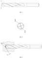
- a usual twist drill comprising a straight shank and a taper shank
- Fig. 1 the straight shank
- the drilling efficiency is greatly constrained due to limitation of arm strength of a worker, power of the electric tool and the like, thereby resulting in difficult drilling positioning, low speed and low efficiency.
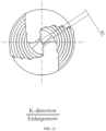
- Fig. 1 when the twist drill with such a conventional structure is used for drilling, the processing of a metal cutting amount in a corresponding size is simultaneously completed by two symmetrically distributed linear cutting blades so that a relatively large power is required during drilling. Meanwhile, relatively large reaction forces are also applied to two cutting edges so that the cutting edges are easy to be damaged. Processing and cutting processes of the twist drill are analyzed and shown in Fig. 2 .
- a traditional twist drill is not easy to be positioned during drilling. Two linear cutting blades always cut simultaneously during drilling.
- the traditional twist drill has an equal cutting metal amount in the entire processing process, has a relatively large cutting torque and power, and is hard to drill.
- CN1375373A discloses a twist drill according to the preamble of claim 1.
- An efficient twist drill for layered drilling according to the invention comprises the features of claim 1.
- the twist drill can be positioned easily during layered drilling operation, has low cutting resistance, produces less cutting heat, has high drilling efficiency and long service life, and greatly improves drilling performance of the drill bit so that a processed circular hole has high precision and few burrs at an edge where the drill bit exits.
- a cutting area of an ordinary twist drill during drilling is generally described at first, as shown in Figs. 1-4 .
- An existing traditional twist drill is not easy to be positioned during drilling. Two linear cutting blades (i.e., main cutting blades 1) always cut simultaneously during drilling.
- the traditional twist drill has an equal cutting metal amount in the entire processing process, has a relatively large cutting torque and power, and is hard to drill.
- An efficient twist drill for layered drilling of the present disclosure comprises a drill bit body 2 which can be the ordinary twist drill.
- the drill body 2 usually comprises a shank portion and an operation portion; the operation portion has a cutting portion at a front end and a guide portion at a rear end; and the shank portion is connected with the guide portion.
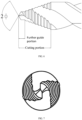
- a plurality of flutes 4 distributed in parallel and at intervals are symmetrically arranged along a flank surface 3 of the cutting portion; the flutes 4 divide main cutting blades into a plurality of first cutting blades 5 and second cutting blades 6; and connecting lines of the first cutting blades 5 and the second cutting blades 6 form a step-like structure (which can also be called a ladder-like structure), i.e., the main cutting blades of the present disclosure are step-like structures. Meanwhile, a cross section of the entire flank surface 3 is also a step-like structure. Certainly, except the main cutting blades, all flank surface portions can also be of other shapes.
- the flank surface adopts a ladder-like structure so that the flank surface does not touch workpieces during cutting; secondly, the strength of the flank surface is enhanced; and thirdly, the flank surface is processed conveniently during manufacturing.
- the second cutting blades 6 are parallel to an axis line of the drill bit body, or an angle of 0-20 degrees is formed between the second cutting blades 6 and the axis line of the drill bit body so that tail ends of the second cutting blades 6 are inclined downwards, and only starting ends of the second cutting blades (i.e., tops of the first cutting blades) touch the workpieces during cutting, as shown in Fig. 13 .
- the second cutting blades 6 are parallel to the axis line of the drill bit body; an angle a of 90-140 degrees is formed between the first cutting blades 5 and the second cutting blades 6; and the first cutting blades are parallel to each other, and certainly, can also be set to be unparallel structures according to actual needs.
- the first cutting blades are parallel to each other in the present disclosure. Since flutes need to be dug in the flank surface to form the ladder-like main cutting blades, the area of the flank surface 3 will be set to be slightly larger, and an angle b formed by the connecting lines of the top endpoints of the first cutting blades 5 (i.e., the angle formed between two main cutting blades) is 20-60 degrees, as shown in Fig. 8 .
- a foremost end of the cutting portion of the present disclosure can also be set in a shape as shown in Fig. 13 .
- a further guide portion i.e., for the first cutting blade and the second cutting blade at the foremost end of the drill bit body, the first cutting blade is in contact with the workpiece at first
- An apex angle of the further guide portion is an angle of 90-140 degrees, and preferably, 118 degrees is set as an optimal angle.
- the angle of the further guide portion can be changed properly according to different processing materials, as shown in Fig. 6 .
- the cutting blades of the further guide portion are relatively short, so the drilling will be relatively stable.
- the main cutting blades are divided into the first cutting blades with relatively small areas, the cutting torque and the power are dispersed by the first cutting blades so as to save efforts during drilling with force.
- the flutes of the present disclosure may be arc-shaped flutes adapted to a radian of the flank surface, or the connecting lines of the flutes form a spiral structure.
- the ladder-like cutting blade of the present disclosure can be applied to drilling cutting tools such as screw taps, expanding drills, countersink drills, reamers, etc. Even only one ladder-like drill bit is arranged, while the ladder-like drill bit can be combined with different cutting tools.
- the flank surface between the flutes forms a step-like circular arc; and a diameter d of the circular arc between the two opposite second cutting blades is gradually increased to form a step-like structure.
- the diameters show a gradually increasing trend; and the increased size can be constant or variable.
- the number of steps and the lengths of the first cutting blades and the second cutting blades can be flexibly selected according to the size of drilled holes and the area of the flank surface. In general, on the flank surfaces with the equal area, the more the number of the divided first cutting blades and second cutting blades is, the better.
- the step-like cutting blades should be provided as many as possible; the diameter between the foremost second cutting blades should be set as small as possible, but the diameter between the foremost second cutting blades will be limited by a standard drill core thickness of the drill bit.
- two linear main cutting blades of the twist drill are designed as a plurality of ladder-like blades to decompose the resistance of the to-be-cut metal layer.
- a guide hole is first drilled by a very small drill point (i.e., the guide portion) of the first section.
- the small drill point is easy to be positioned and drill the small hole due to a small diameter.
- the small hole is gradually expanded by a subsequent gradually-widened ladder blade until a final size of the twist drill is reached.
- the cutting resistance is reduced and the feeding is easy and fast.
Description
- The present disclosure relates to an efficient twist drill for layered drilling.
- If a usual twist drill (comprising a straight shank and a taper shank), with reference to
Fig. 1 (the straight shank), is used in a workplace away from a drilling machine and other metal cutting machine tools, when a handheld electric tool is used for drilling operation, the drilling efficiency is greatly constrained due to limitation of arm strength of a worker, power of the electric tool and the like, thereby resulting in difficult drilling positioning, low speed and low efficiency. - As shown in
Fig. 1 , when the twist drill with such a conventional structure is used for drilling, the processing of a metal cutting amount in a corresponding size is simultaneously completed by two symmetrically distributed linear cutting blades so that a relatively large power is required during drilling. Meanwhile, relatively large reaction forces are also applied to two cutting edges so that the cutting edges are easy to be damaged. Processing and cutting processes of the twist drill are analyzed and shown inFig. 2 . - A traditional twist drill is not easy to be positioned during drilling. Two linear cutting blades always cut simultaneously during drilling. The traditional twist drill has an equal cutting metal amount in the entire processing process, has a relatively large cutting torque and power, and is hard to drill.
-
CN1375373A discloses a twist drill according to the preamble ofclaim 1. - The purpose of the present disclosure is to provide a tool capable of cutting rapidly and drilling while prolonging service life of the tool and increasing operation efficiency. The above purpose is realized by the following technical solution:
An efficient twist drill for layered drilling according to the invention comprises the features ofclaim 1. - Preferable embodiments are defined in the dependent claims.
- Through step-like cutting, the twist drill can be positioned easily during layered drilling operation, has low cutting resistance, produces less cutting heat, has high drilling efficiency and long service life, and greatly improves drilling performance of the drill bit so that a processed circular hole has high precision and few burrs at an edge where the drill bit exits.
-
-
Fig. 1 is a structural schematic diagram of an existing twist drill, wherein cutting blades are two linear cutting edges; -
Fig. 2 is a side view ofFig. 1 ; -
Fig. 3 is a schematic diagram of cutting of cutting edges during drilling of an existing twist drill; -
Fig. 4 is a partial enlarged view ofFig. 3 ; -
Fig. 5 is a schematic diagram of the present disclosure; -
Fig. 6 is a partial enlarged view ofFig. 5 ; -
Fig. 7 is a side view ofFig. 5 ; -
Fig. 8 is a partial enlarged view ofFig. 5 ; -
Fig. 9 is a schematic diagram of the present disclosure during drilling; -
Fig. 10 is a partial enlarged view ofFig. 9 ; -
Fig. 11 is a schematic diagram of the present disclosure; -
Fig. 12 is a side view ofFig. 11 ; and -
Fig. 13 is another structural schematic diagram of a cutting portion of the present disclosure. - The present disclosure is described in detail below with reference to drawings.
- A cutting area of an ordinary twist drill during drilling is generally described at first, as shown in
Figs. 1-4 . - An existing traditional twist drill is not easy to be positioned during drilling. Two linear cutting blades (i.e., main cutting blades 1) always cut simultaneously during drilling. The traditional twist drill has an equal cutting metal amount in the entire processing process, has a relatively large cutting torque and power, and is hard to drill. The traditional twist drill has a single-blade cutting area of S1= S2 = W × h and a total cutting area of S = 2S1 = 2S2 = 2 × W × h during drilling.
- Then, a structure of the present disclosure is described in detail below, as shown in
Figs. 5-12 . - An efficient twist drill for layered drilling of the present disclosure comprises a
drill bit body 2 which can be the ordinary twist drill. Thedrill body 2 usually comprises a shank portion and an operation portion; the operation portion has a cutting portion at a front end and a guide portion at a rear end; and the shank portion is connected with the guide portion. A plurality offlutes 4 distributed in parallel and at intervals are symmetrically arranged along aflank surface 3 of the cutting portion; theflutes 4 divide main cutting blades into a plurality offirst cutting blades 5 andsecond cutting blades 6; and connecting lines of thefirst cutting blades 5 and thesecond cutting blades 6 form a step-like structure (which can also be called a ladder-like structure), i.e., the main cutting blades of the present disclosure are step-like structures. Meanwhile, a cross section of theentire flank surface 3 is also a step-like structure. Certainly, except the main cutting blades, all flank surface portions can also be of other shapes. The flank surface adopts a ladder-like structure so that the flank surface does not touch workpieces during cutting; secondly, the strength of the flank surface is enhanced; and thirdly, the flank surface is processed conveniently during manufacturing. Thesecond cutting blades 6 are parallel to an axis line of the drill bit body, or an angle of 0-20 degrees is formed between thesecond cutting blades 6 and the axis line of the drill bit body so that tail ends of thesecond cutting blades 6 are inclined downwards, and only starting ends of the second cutting blades (i.e., tops of the first cutting blades) touch the workpieces during cutting, as shown inFig. 13 . - Preferably, the
second cutting blades 6 are parallel to the axis line of the drill bit body; an angle a of 90-140 degrees is formed between thefirst cutting blades 5 and thesecond cutting blades 6; and the first cutting blades are parallel to each other, and certainly, can also be set to be unparallel structures according to actual needs. Preferably, the first cutting blades are parallel to each other in the present disclosure. Since flutes need to be dug in the flank surface to form the ladder-like main cutting blades, the area of theflank surface 3 will be set to be slightly larger, and an angle b formed by the connecting lines of the top endpoints of the first cutting blades 5 (i.e., the angle formed between two main cutting blades) is 20-60 degrees, as shown inFig. 8 . Certainly, a foremost end of the cutting portion of the present disclosure can also be set in a shape as shown inFig. 13 .
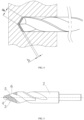
In order to drill stably, a further guide portion (i.e., for the first cutting blade and the second cutting blade at the foremost end of the drill bit body, the first cutting blade is in contact with the workpiece at first) is formed at the foremost end of thedrill bit body 2. An apex angle of the further guide portion is an angle of 90-140 degrees, and preferably, 118 degrees is set as an optimal angle. Certainly, the angle of the further guide portion can be changed properly according to different processing materials, as shown inFig. 6 .
The cutting blades of the further guide portion are relatively short, so the drilling will be relatively stable. Moreover, since the main cutting blades are divided into the first cutting blades with relatively small areas, the cutting torque and the power are dispersed by the first cutting blades so as to save efforts during drilling with force. It should be noted that the foremost first cutting blade in contact with the workpiece at first in the present disclosure may be unparallel to the subsequent first cutting blade.
The flutes of the present disclosure may be arc-shaped flutes adapted to a radian of the flank surface, or the connecting lines of the flutes form a spiral structure. The ladder-like cutting blade of the present disclosure can be applied to drilling cutting tools such as screw taps, expanding drills, countersink drills, reamers, etc. Even only one ladder-like drill bit is arranged, while the ladder-like drill bit can be combined with different cutting tools.
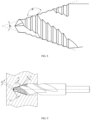
As shown inFig. 11 , the flank surface between the flutes forms a step-like circular arc; and a diameter d of the circular arc between the two opposite second cutting blades is gradually increased to form a step-like structure. For example, from a diameter d1 between the foremost second cutting blades to a diameter dn between the last second cutting blades, the diameters show a gradually increasing trend; and the increased size can be constant or variable.
In the present disclosure, the number of steps and the lengths of the first cutting blades and the second cutting blades can be flexibly selected according to the size of drilled holes and the area of the flank surface. In general, on the flank surfaces with the equal area, the more the number of the divided first cutting blades and second cutting blades is, the better. In this case, the smaller the contact area between the first cutting blades and the workpiece is, the smaller the resistance borne by the cutting tool during drilling is, and the easier the drilling is. In view of the above characteristics, the step-like cutting blades should be provided as many as possible; the diameter between the foremost second cutting blades should be set as small as possible, but the diameter between the foremost second cutting blades will be limited by a standard drill core thickness of the drill bit. - In the present disclosure, two linear main cutting blades of the twist drill are designed as a plurality of ladder-like blades to decompose the resistance of the to-be-cut metal layer. As shown in
Figs. 9 and10 , a cut large block S is decomposed into n small blocks Si; the area of each small block Si is Si = Wi × hi, Sn = Wn × hi; and the total cutting area is S = S1 + ... + Si + ... + Sn. - When the drill bit starts to come into contact with the surface of the workpiece, a guide hole is first drilled by a very small drill point (i.e., the guide portion) of the first section. The small drill point is easy to be positioned and drill the small hole due to a small diameter. Then, the small hole is gradually expanded by a subsequent gradually-widened ladder blade until a final size of the twist drill is reached. In the gradual drilling and hole expanding processes, compared with the one-process continuous cutting of the linear cutting blade of a conventional twist drill, the cutting resistance is reduced and the feeding is easy and fast.
- The beneficial effects brought by the technical solutions of the present disclosure are as follows:
- (1) in the whole processing process, the drilling force is relatively small, uniform and reasonable;
- (2) the artificial hand-held electric tools can be operated stably and durably;
- (3) the drilling processing precision is ensured, and the occurrence of equipment and personal accidents is avoided;
- (4) all the step-like cutting edges of the cutting tool are worn uniformly and consistently, thereby prolonging service of the cutting tool (about 3-8 times);
- (5) unnecessary damage of the cutting tool during use and scrapped workpieces are reduced;
- (6) the processing difficulty and cost are reduced, and processing efficiency is increased; and
- (7) a flange has few burrs at an edge where the drill bit exits.
- The above are only preferred embodiments of the present disclosure and are not intended to limit the embodiments of the present disclosure.
Claims (4)
- An efficient twist drill for layered drilling, comprising a drill bit body (2),wherein the drill bit body (2) comprises a shank portion and an operation portion; the shank portion is connected with the operation portion; the operation portion has a cutting portion at a front end and a guide portion at a rear end, and the shank portion is connected with the guide portion, wherein a plurality of flutes (4) forming a spiral structure and distributed in parallel and at intervals are symmetrically arranged along a flank surface (3) of the cutting portion and the guide portion; the flutes (4) divide main cutting blades into a plurality of first cutting blades (5) and second cutting blades (6), and the first cutting blades (5) on a respective step are equal in height,wherein from a diameter (d) between the foremost second cutting blades (d1) to a diameter of the last second cutting blades (d2), the diameters show a gradually increasing trend,wherein a length (L1) of the guide portion at the rear end is larger than the length (L3) of the cutting portion at the front end;characterized in thatin a front view of the twist drill, connecting lines of the first cutting blades (5) andthe second cutting blades (6) form a step-like structure.
- The efficient twist drill for layered drilling according to claim 1, wherein the second cutting blades (6) are parallel to an axis line of the drill bit body (2); and an angle of 90-140 degrees is formed between the first cutting blades (5) and the second cutting blades (6).
- The efficient twist drill for layered drilling according to claim 1, wherein an acute angle is formed between the second cutting blades (6) and the axis line of the drill bit body (2), so that tail ends of the second cutting blades (6) are inclined downwards.
- The efficient twist drill for layered drilling according to claim 1, wherein an angle formed by connecting lines of top endpoints of the first cutting blades (5) is 20-60 degrees.
Priority Applications (1)
| Application Number | Priority Date | Filing Date | Title |
|---|---|---|---|
| EP23163838.8A EP4227031A1 (en) | 2016-02-14 | 2016-02-14 | High efficiency step-structured twist drill |
Applications Claiming Priority (1)
| Application Number | Priority Date | Filing Date | Title |
|---|---|---|---|
| PCT/CN2016/073767 WO2017136966A1 (en) | 2016-02-14 | 2016-02-14 | High efficiency step-structured twist drill |
Related Child Applications (1)
| Application Number | Title | Priority Date | Filing Date |
|---|---|---|---|
| EP23163838.8A Division EP4227031A1 (en) | 2016-02-14 | 2016-02-14 | High efficiency step-structured twist drill |
Publications (3)
| Publication Number | Publication Date |
|---|---|
| EP3305447A1 EP3305447A1 (en) | 2018-04-11 |
| EP3305447A4 EP3305447A4 (en) | 2019-02-13 |
| EP3305447B1 true EP3305447B1 (en) | 2023-03-29 |
Family
ID=59563715
Family Applications (2)
| Application Number | Title | Priority Date | Filing Date |
|---|---|---|---|
| EP23163838.8A Pending EP4227031A1 (en) | 2016-02-14 | 2016-02-14 | High efficiency step-structured twist drill |
| EP16889695.9A Active EP3305447B1 (en) | 2016-02-14 | 2016-02-14 | Step-structured twist drill |
Family Applications Before (1)
| Application Number | Title | Priority Date | Filing Date |
|---|---|---|---|
| EP23163838.8A Pending EP4227031A1 (en) | 2016-02-14 | 2016-02-14 | High efficiency step-structured twist drill |
Country Status (7)
| Country | Link |
|---|---|
| US (1) | US20180133808A1 (en) |
| EP (2) | EP4227031A1 (en) |
| DK (1) | DK3305447T3 (en) |
| ES (1) | ES2947506T3 (en) |
| FI (1) | FI3305447T3 (en) |
| PL (1) | PL3305447T3 (en) |
| WO (1) | WO2017136966A1 (en) |
Families Citing this family (12)
| Publication number | Priority date | Publication date | Assignee | Title |
|---|---|---|---|---|
| US11007583B2 (en) * | 2016-02-14 | 2021-05-18 | Hongjia Wang | Twist drill |
| US20210154749A1 (en) * | 2018-01-29 | 2021-05-27 | Milwaukee Electric Tool Corporation | Drill bit |
| CN110802259B (en) * | 2019-11-28 | 2021-07-06 | 上海钰工机电有限公司 | Twist drill |
| DE102019135404A1 (en) * | 2019-12-20 | 2021-06-24 | Gühring KG | Twist drill with a stepped cutting tip |
| CN214720850U (en) | 2021-06-11 | 2021-11-16 | 江苏锋源工具有限公司 | Spiral stepped drill point twist drill |
| DE102021121199A1 (en) | 2021-08-16 | 2023-02-16 | Gühring KG | Twist drills with a step-structured cutting tip and undercuts |
| DE202021004071U1 (en) | 2021-08-16 | 2022-08-01 | Gühring KG | Twist drills with a step-structured cutting tip and undercuts |
| DE202021004070U1 (en) | 2021-08-16 | 2022-08-01 | Gühring KG | Twist drills with a stepped structured cutting tip with divergent riser sections |
| DE202021004067U1 (en) | 2021-08-16 | 2022-08-04 | Gühring KG | Twist drills with a stepped structured cutting tip with convergent riser sections |
| DE202021004069U1 (en) | 2021-08-19 | 2022-08-22 | Gühring KG | Twist drills with a step-structured cutting tip and different cutting angles |
| DE102022110659A1 (en) * | 2022-05-02 | 2023-11-02 | Yuzheng Chen | Step drill |
| CN117655377A (en) * | 2022-08-24 | 2024-03-08 | 上海钰工工具有限公司 | Step drill and method for drilling and cutting workpiece by using step drill |
Citations (21)
| Publication number | Priority date | Publication date | Assignee | Title |
|---|---|---|---|---|
| US2193186A (en) | 1938-06-06 | 1940-03-12 | Herbert G Hard | Twist drill |
| JPH0435812U (en) | 1990-07-17 | 1992-03-25 | ||
| WO1997031741A1 (en) * | 1996-03-01 | 1997-09-04 | Kloester, Ian, Albert | Drill |
| CN1375373A (en) * | 2001-03-21 | 2002-10-23 | 周安善 | Efficient universal twist drill with two milling cutter edges and its sharpening method |
| DE20303656U1 (en) | 2003-03-06 | 2003-05-08 | Quanz Reiner | Conical drill bit adjacent step-graduated sections linked by conical transition zones |
| US6652203B1 (en) | 2002-08-30 | 2003-11-25 | Credo Technology Corporation | Precision drill bits |
| EP1512476A2 (en) | 2003-09-08 | 2005-03-09 | BLACK & DECKER INC. | Self-centering drill bit with pilot tip |
| US20060210949A1 (en) | 2003-03-13 | 2006-09-21 | Hans Stoop | Pilot drill, step drill, and drill set for dental implant technology |
| DE202008000368U1 (en) | 2008-01-09 | 2008-03-13 | RUKO GmbH Präzisionswerkzeuge | Multi-stage drill with drill stop |
| US20080166195A1 (en) | 2007-01-05 | 2008-07-10 | Gentry Charles L | Spiral drill bit and method of forming same |
| KR20090014835A (en) | 2007-08-07 | 2009-02-11 | 오스템임플란트 주식회사 | A dental implant drill having a multi-step structure |
| CN201223962Y (en) | 2008-07-21 | 2009-04-22 | 哈尔滨汽轮机厂有限责任公司 | Step chip dividing groove deep hole drill |
| CN101977713A (en) | 2008-03-19 | 2011-02-16 | 李仕清 | A helical bit tool |
| CN202180238U (en) * | 2011-06-09 | 2012-04-04 | 上海钰工机电有限公司 | Combined-land fixed-feeding-amount step drill |
| WO2013042874A1 (en) | 2011-09-22 | 2013-03-28 | Osstemimplant Co., Ltd. | Dental drill, drill set, and method of drilling alveolar bone |
| WO2013143348A1 (en) | 2012-03-27 | 2013-10-03 | 北京迪蒙集智科技有限公司 | Twist drill for drilling fine holes on high-strength and high-hardness alloy material |
| CN203356678U (en) | 2013-02-01 | 2013-12-25 | 周安善 | Twist drill with segmented main cutting blades and asymmetric blade opening height |
| CN203711939U (en) | 2013-05-23 | 2014-07-16 | 常州市卡特精密工具有限公司 | Step forming drill |
| US20140363244A1 (en) | 2013-06-06 | 2014-12-11 | Milwaukee Electric Tool Corporation | Step drill bit |
| CN204953985U (en) | 2015-08-26 | 2016-01-13 | 浙江欣兴工具有限公司 | Twist drill |
| WO2016207728A1 (en) | 2015-06-23 | 2016-12-29 | The Research Foundation For The State University Of New York | Multi-diameter drill bit |
Family Cites Families (12)
| Publication number | Priority date | Publication date | Assignee | Title |
|---|---|---|---|---|
| GB123605A (en) * | 1918-03-05 | 1919-03-05 | Vickers Ltd | Improvements in or relating to Boring Tools. |
| US4582458A (en) * | 1984-08-09 | 1986-04-15 | American Saw & Mfg. Company | Stepped drill construction |
| JPS6316912A (en) * | 1986-07-10 | 1988-01-23 | Gotou Matsue | Multi-stage drill |
| DE9414659U1 (en) * | 1994-09-09 | 1994-11-17 | Duerr Praezisionswerkzeuge Gmb | Multi-step drill |
| US5466100A (en) * | 1994-10-24 | 1995-11-14 | Alfa Manufacturing Industries, Inc. | Multi-stepped power drill bit having handle chuck adaptor |
| GB2318072A (en) * | 1996-09-21 | 1998-04-15 | Plansee Tizit Gmbh | Masonry bit |
| DE29904042U1 (en) * | 1999-03-05 | 1999-07-29 | Daehn & Klein Gmbh | Step drill |
| US6890133B2 (en) * | 2002-10-18 | 2005-05-10 | Irwin Industrial Tool Company | Stepped drill bit having split tip |
| CN102126039A (en) * | 2011-01-22 | 2011-07-20 | 李仕清 | Spiral cutter for composite positioned cutting |
| CN103084629A (en) * | 2013-02-01 | 2013-05-08 | 周安善 | Twist drill with segmented main cutting blades and asymmetric blade opening height |
| CN203649486U (en) * | 2013-12-23 | 2014-06-18 | 广东鸿泰科技股份有限公司 | Stepped drill and hole site processing device with stepped drill |
| CN205551557U (en) * | 2016-02-14 | 2016-09-07 | 上海钰工机电有限公司 | High -efficient fluted drill of layering drilling |
-
2016
- 2016-02-14 EP EP23163838.8A patent/EP4227031A1/en active Pending
- 2016-02-14 WO PCT/CN2016/073767 patent/WO2017136966A1/en unknown
- 2016-02-14 FI FIEP16889695.9T patent/FI3305447T3/en active
- 2016-02-14 ES ES16889695T patent/ES2947506T3/en active Active
- 2016-02-14 DK DK16889695.9T patent/DK3305447T3/en active
- 2016-02-14 EP EP16889695.9A patent/EP3305447B1/en active Active
- 2016-02-14 PL PL16889695.9T patent/PL3305447T3/en unknown
-
2017
- 2017-12-19 US US15/847,900 patent/US20180133808A1/en not_active Abandoned
Patent Citations (22)
| Publication number | Priority date | Publication date | Assignee | Title |
|---|---|---|---|---|
| US2193186A (en) | 1938-06-06 | 1940-03-12 | Herbert G Hard | Twist drill |
| JPH0435812U (en) | 1990-07-17 | 1992-03-25 | ||
| WO1997031741A1 (en) * | 1996-03-01 | 1997-09-04 | Kloester, Ian, Albert | Drill |
| CN1375373A (en) * | 2001-03-21 | 2002-10-23 | 周安善 | Efficient universal twist drill with two milling cutter edges and its sharpening method |
| US6652203B1 (en) | 2002-08-30 | 2003-11-25 | Credo Technology Corporation | Precision drill bits |
| DE20303656U1 (en) | 2003-03-06 | 2003-05-08 | Quanz Reiner | Conical drill bit adjacent step-graduated sections linked by conical transition zones |
| US20060210949A1 (en) | 2003-03-13 | 2006-09-21 | Hans Stoop | Pilot drill, step drill, and drill set for dental implant technology |
| EP1512476A2 (en) | 2003-09-08 | 2005-03-09 | BLACK & DECKER INC. | Self-centering drill bit with pilot tip |
| US20080166195A1 (en) | 2007-01-05 | 2008-07-10 | Gentry Charles L | Spiral drill bit and method of forming same |
| KR20090014835A (en) | 2007-08-07 | 2009-02-11 | 오스템임플란트 주식회사 | A dental implant drill having a multi-step structure |
| DE202008000368U1 (en) | 2008-01-09 | 2008-03-13 | RUKO GmbH Präzisionswerkzeuge | Multi-stage drill with drill stop |
| CN101977713A (en) | 2008-03-19 | 2011-02-16 | 李仕清 | A helical bit tool |
| US20110116884A1 (en) | 2008-03-19 | 2011-05-19 | Shiqing Li | Helical bit tool |
| CN201223962Y (en) | 2008-07-21 | 2009-04-22 | 哈尔滨汽轮机厂有限责任公司 | Step chip dividing groove deep hole drill |
| CN202180238U (en) * | 2011-06-09 | 2012-04-04 | 上海钰工机电有限公司 | Combined-land fixed-feeding-amount step drill |
| WO2013042874A1 (en) | 2011-09-22 | 2013-03-28 | Osstemimplant Co., Ltd. | Dental drill, drill set, and method of drilling alveolar bone |
| WO2013143348A1 (en) | 2012-03-27 | 2013-10-03 | 北京迪蒙集智科技有限公司 | Twist drill for drilling fine holes on high-strength and high-hardness alloy material |
| CN203356678U (en) | 2013-02-01 | 2013-12-25 | 周安善 | Twist drill with segmented main cutting blades and asymmetric blade opening height |
| CN203711939U (en) | 2013-05-23 | 2014-07-16 | 常州市卡特精密工具有限公司 | Step forming drill |
| US20140363244A1 (en) | 2013-06-06 | 2014-12-11 | Milwaukee Electric Tool Corporation | Step drill bit |
| WO2016207728A1 (en) | 2015-06-23 | 2016-12-29 | The Research Foundation For The State University Of New York | Multi-diameter drill bit |
| CN204953985U (en) | 2015-08-26 | 2016-01-13 | 浙江欣兴工具有限公司 | Twist drill |
Non-Patent Citations (3)
| Title |
|---|
| MARCUS ABBOUD; RAFAEL ARCESIO DELGADO‐RUIZ; ALLAN KUCINE; SIHANA RUGOVA; JULIAN BALANTA; JOSE LUIS CALVO‐GUIRADO: "Multistepped Drill Design for Single‐Stage Implant Site Preparation: Experimental Study in Type 2 Bone", CLINICAL IMPLANT DENTISTRY AND RELATED RESEARCH, DECKER, HAMILTON, CA, vol. 17, 29 September 2014 (2014-09-29), CA , pages e472 - e485, XP072269589, ISSN: 1523-0899, DOI: 10.1111/cid.12273 |
| THOMAS J. DROZDA: "Tool and Manufacturing Engineers Handbook, 4th ed", 1 January 1983, pages: 9.14, 9.15, 9.90, 9.91, 9.96, XP093152436 |
| VIKTOR P ASTAKHOV: "Drills - Science and Technology of Advanced Operations", 1 January 2014, CRC PRESS, pages: 266 - 268, XP093152441 |
Also Published As
| Publication number | Publication date |
|---|---|
| ES2947506T3 (en) | 2023-08-10 |
| EP4227031A1 (en) | 2023-08-16 |
| PL3305447T3 (en) | 2023-07-31 |
| EP3305447A4 (en) | 2019-02-13 |
| WO2017136966A1 (en) | 2017-08-17 |
| EP3305447A1 (en) | 2018-04-11 |
| DK3305447T3 (en) | 2023-07-03 |
| FI3305447T3 (en) | 2023-06-13 |
| US20180133808A1 (en) | 2018-05-17 |
Similar Documents
| Publication | Publication Date | Title |
|---|---|---|
| EP3305447B1 (en) | Step-structured twist drill | |
| US7357606B1 (en) | Self-advancing step-tap tool | |
| EP2535129B1 (en) | Drill bit | |
| EP2217417B1 (en) | Auger bit including a reamer | |
| HU229112B1 (en) | Thread milling tool having helical flutes | |
| JP2011104766A (en) | Drill for composite material, and machining method and apparatus using the same | |
| US11865627B1 (en) | Twist drill | |
| CN205551557U (en) | High -efficient fluted drill of layering drilling | |
| CN214392488U (en) | Annular cutter for drilling composite material | |
| KR102027299B1 (en) | Carbon fiber reinforced plastic processing shape drill | |
| KR100628885B1 (en) | Carbide step drill to process final hole of material without steel having reserve hole | |
| CN203197391U (en) | Backwards-pulled taper reamer | |
| GB2443543A (en) | Improved spade-type bit | |
| CN215786995U (en) | Composite forming milling cutter | |
| JP2006198685A (en) | Screw machining tool | |
| CN203304646U (en) | Chip dividing straight flute bit | |
| JP3808455B2 (en) | Chip cutting tool for tapping and female thread machining method | |
| EP1153685A1 (en) | Multi-fluted milling cutter | |
| CN215824341U (en) | Integrated drill | |
| CN210789369U (en) | Drill bit capable of reducing burrs and drilling machine assembly | |
| CN217727373U (en) | Diamond reamer | |
| CN210789376U (en) | Quick chamfer drill bit and drilling machine assembly | |
| CN214720850U (en) | Spiral stepped drill point twist drill | |
| CN219130877U (en) | PCD drill bit | |
| CN203738091U (en) | Auger bit with annular blades |
Legal Events
| Date | Code | Title | Description |
|---|---|---|---|
| STAA | Information on the status of an ep patent application or granted ep patent |
Free format text: STATUS: THE INTERNATIONAL PUBLICATION HAS BEEN MADE |
|
| PUAI | Public reference made under article 153(3) epc to a published international application that has entered the european phase |
Free format text: ORIGINAL CODE: 0009012 |
|
| STAA | Information on the status of an ep patent application or granted ep patent |
Free format text: STATUS: REQUEST FOR EXAMINATION WAS MADE |
|
| 17P | Request for examination filed |
Effective date: 20180103 |
|
| AK | Designated contracting states |
Kind code of ref document: A1 Designated state(s): AL AT BE BG CH CY CZ DE DK EE ES FI FR GB GR HR HU IE IS IT LI LT LU LV MC MK MT NL NO PL PT RO RS SE SI SK SM TR |
|
| AX | Request for extension of the european patent |
Extension state: BA ME |
|
| A4 | Supplementary search report drawn up and despatched |
Effective date: 20190110 |
|
| RIC1 | Information provided on ipc code assigned before grant |
Ipc: B23B 51/02 20060101AFI20190104BHEP Ipc: B23B 51/00 20060101ALI20190104BHEP |
|
| DAV | Request for validation of the european patent (deleted) | ||
| DAX | Request for extension of the european patent (deleted) | ||
| STAA | Information on the status of an ep patent application or granted ep patent |
Free format text: STATUS: EXAMINATION IS IN PROGRESS |
|
| STAA | Information on the status of an ep patent application or granted ep patent |
Free format text: STATUS: EXAMINATION IS IN PROGRESS |
|
| 17Q | First examination report despatched |
Effective date: 20210111 |
|
| STAA | Information on the status of an ep patent application or granted ep patent |
Free format text: STATUS: EXAMINATION IS IN PROGRESS |
|
| RAP1 | Party data changed (applicant data changed or rights of an application transferred) |
Owner name: TEC-SPIRAL ENTERPRISES TOOLS CO., LTD. |
|
| GRAP | Despatch of communication of intention to grant a patent |
Free format text: ORIGINAL CODE: EPIDOSNIGR1 |
|
| STAA | Information on the status of an ep patent application or granted ep patent |
Free format text: STATUS: GRANT OF PATENT IS INTENDED |
|
| INTG | Intention to grant announced |
Effective date: 20221130 |
|
| GRAS | Grant fee paid |
Free format text: ORIGINAL CODE: EPIDOSNIGR3 |
|
| GRAA | (expected) grant |
Free format text: ORIGINAL CODE: 0009210 |
|
| STAA | Information on the status of an ep patent application or granted ep patent |
Free format text: STATUS: THE PATENT HAS BEEN GRANTED |
|
| AK | Designated contracting states |
Kind code of ref document: B1 Designated state(s): AL AT BE BG CH CY CZ DE DK EE ES FI FR GB GR HR HU IE IS IT LI LT LU LV MC MK MT NL NO PL PT RO RS SE SI SK SM TR |
|
| REG | Reference to a national code |
Ref country code: GB Ref legal event code: FG4D |
|
| REG | Reference to a national code |
Ref country code: CH Ref legal event code: EP |
|
| REG | Reference to a national code |
Ref country code: AT Ref legal event code: REF Ref document number: 1556323 Country of ref document: AT Kind code of ref document: T Effective date: 20230415 |
|
| REG | Reference to a national code |
Ref country code: DE Ref legal event code: R096 Ref document number: 602016078592 Country of ref document: DE |
|
| REG | Reference to a national code |
Ref country code: IE Ref legal event code: FG4D |
|
| REG | Reference to a national code |
Ref country code: DE Ref legal event code: R026 Ref document number: 602016078592 Country of ref document: DE |
|
| REG | Reference to a national code |
Ref country code: SE Ref legal event code: TRGR |
|
| PLBI | Opposition filed |
Free format text: ORIGINAL CODE: 0009260 |
|
| P01 | Opt-out of the competence of the unified patent court (upc) registered |
Effective date: 20230508 |
|
| REG | Reference to a national code |
Ref country code: DK Ref legal event code: T3 Effective date: 20230629 |
|
| REG | Reference to a national code |
Ref country code: NL Ref legal event code: FP |
|
| REG | Reference to a national code |
Ref country code: LT Ref legal event code: MG9D |
|
| 26 | Opposition filed |
Opponent name: RUKO GMBH PRAEZISIONSWERKZEUGE Effective date: 20230605 |
|
| PG25 | Lapsed in a contracting state [announced via postgrant information from national office to epo] |
Ref country code: RS Free format text: LAPSE BECAUSE OF FAILURE TO SUBMIT A TRANSLATION OF THE DESCRIPTION OR TO PAY THE FEE WITHIN THE PRESCRIBED TIME-LIMIT Effective date: 20230329 Ref country code: LV Free format text: LAPSE BECAUSE OF FAILURE TO SUBMIT A TRANSLATION OF THE DESCRIPTION OR TO PAY THE FEE WITHIN THE PRESCRIBED TIME-LIMIT Effective date: 20230329 Ref country code: LT Free format text: LAPSE BECAUSE OF FAILURE TO SUBMIT A TRANSLATION OF THE DESCRIPTION OR TO PAY THE FEE WITHIN THE PRESCRIBED TIME-LIMIT Effective date: 20230329 Ref country code: HR Free format text: LAPSE BECAUSE OF FAILURE TO SUBMIT A TRANSLATION OF THE DESCRIPTION OR TO PAY THE FEE WITHIN THE PRESCRIBED TIME-LIMIT Effective date: 20230329 |
|
| REG | Reference to a national code |
Ref country code: NO Ref legal event code: T2 Effective date: 20230329 |
|
| REG | Reference to a national code |
Ref country code: ES Ref legal event code: FG2A Ref document number: 2947506 Country of ref document: ES Kind code of ref document: T3 Effective date: 20230810 |
|
| PG25 | Lapsed in a contracting state [announced via postgrant information from national office to epo] |
Ref country code: GR Free format text: LAPSE BECAUSE OF FAILURE TO SUBMIT A TRANSLATION OF THE DESCRIPTION OR TO PAY THE FEE WITHIN THE PRESCRIBED TIME-LIMIT Effective date: 20230630 |
|
| PG25 | Lapsed in a contracting state [announced via postgrant information from national office to epo] |
Ref country code: SM Free format text: LAPSE BECAUSE OF FAILURE TO SUBMIT A TRANSLATION OF THE DESCRIPTION OR TO PAY THE FEE WITHIN THE PRESCRIBED TIME-LIMIT Effective date: 20230329 Ref country code: RO Free format text: LAPSE BECAUSE OF FAILURE TO SUBMIT A TRANSLATION OF THE DESCRIPTION OR TO PAY THE FEE WITHIN THE PRESCRIBED TIME-LIMIT Effective date: 20230329 Ref country code: PT Free format text: LAPSE BECAUSE OF FAILURE TO SUBMIT A TRANSLATION OF THE DESCRIPTION OR TO PAY THE FEE WITHIN THE PRESCRIBED TIME-LIMIT Effective date: 20230731 Ref country code: EE Free format text: LAPSE BECAUSE OF FAILURE TO SUBMIT A TRANSLATION OF THE DESCRIPTION OR TO PAY THE FEE WITHIN THE PRESCRIBED TIME-LIMIT Effective date: 20230329 |
|
| PG25 | Lapsed in a contracting state [announced via postgrant information from national office to epo] |
Ref country code: SK Free format text: LAPSE BECAUSE OF FAILURE TO SUBMIT A TRANSLATION OF THE DESCRIPTION OR TO PAY THE FEE WITHIN THE PRESCRIBED TIME-LIMIT Effective date: 20230329 Ref country code: IS Free format text: LAPSE BECAUSE OF FAILURE TO SUBMIT A TRANSLATION OF THE DESCRIPTION OR TO PAY THE FEE WITHIN THE PRESCRIBED TIME-LIMIT Effective date: 20230729 |
|
| TPAC | Observations filed by third parties |
Free format text: ORIGINAL CODE: EPIDOSNTIPA |
|
| TPAC | Observations filed by third parties |
Free format text: ORIGINAL CODE: EPIDOSNTIPA |
|
| PLBI | Opposition filed |
Free format text: ORIGINAL CODE: 0009260 |
|
| PLAB | Opposition data, opponent's data or that of the opponent's representative modified |
Free format text: ORIGINAL CODE: 0009299OPPO |
|
| PLBI | Opposition filed |
Free format text: ORIGINAL CODE: 0009260 |
|
| PLAX | Notice of opposition and request to file observation + time limit sent |
Free format text: ORIGINAL CODE: EPIDOSNOBS2 |
|
| 26 | Opposition filed |
Opponent name: PTG PRAEZISIONS-TECHNIK HANDELSGESELLSCHAFT MBH Effective date: 20231229 |
|
| 26 | Opposition filed |
Opponent name: STANLEY BLACK & DECKER, INC. Effective date: 20231229 |
|
| R26 | Opposition filed (corrected) |
Opponent name: PTG PRAEZISIONS-TECHNIK HANDELSGESELLSCHAFT MBH Effective date: 20231229 |
|
| REG | Reference to a national code |
Ref country code: DE Ref legal event code: R082 Ref document number: 602016078592 Country of ref document: DE Representative=s name: WUESTHOFF & WUESTHOFF PATENTANWAELTE UND RECHT, DE |
|
| PGFP | Annual fee paid to national office [announced via postgrant information from national office to epo] |
Ref country code: NL Payment date: 20240229 Year of fee payment: 9 Ref country code: IE Payment date: 20240221 Year of fee payment: 9 Ref country code: ES Payment date: 20240306 Year of fee payment: 9 |