EP3305433A1 - Device for manufacturing coil spring and method for manufacturing coil spring - Google Patents
Device for manufacturing coil spring and method for manufacturing coil spring Download PDFInfo
- Publication number
- EP3305433A1 EP3305433A1 EP16802919.7A EP16802919A EP3305433A1 EP 3305433 A1 EP3305433 A1 EP 3305433A1 EP 16802919 A EP16802919 A EP 16802919A EP 3305433 A1 EP3305433 A1 EP 3305433A1
- Authority
- EP
- European Patent Office
- Prior art keywords
- pin
- continuous
- coil spring
- distal end
- continuous material
- Prior art date
- Legal status (The legal status is an assumption and is not a legal conclusion. Google has not performed a legal analysis and makes no representation as to the accuracy of the status listed.)
- Withdrawn
Links
Images




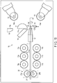


Classifications
-
- B—PERFORMING OPERATIONS; TRANSPORTING
- B21—MECHANICAL METAL-WORKING WITHOUT ESSENTIALLY REMOVING MATERIAL; PUNCHING METAL
- B21F—WORKING OR PROCESSING OF METAL WIRE
- B21F35/00—Making springs from wire
- B21F35/02—Bending or deforming ends of coil springs to special shape
-
- B—PERFORMING OPERATIONS; TRANSPORTING
- B21—MECHANICAL METAL-WORKING WITHOUT ESSENTIALLY REMOVING MATERIAL; PUNCHING METAL
- B21F—WORKING OR PROCESSING OF METAL WIRE
- B21F1/00—Bending wire other than coiling; Straightening wire
- B21F1/02—Straightening
-
- B—PERFORMING OPERATIONS; TRANSPORTING
- B21—MECHANICAL METAL-WORKING WITHOUT ESSENTIALLY REMOVING MATERIAL; PUNCHING METAL
- B21F—WORKING OR PROCESSING OF METAL WIRE
- B21F1/00—Bending wire other than coiling; Straightening wire
- B21F1/02—Straightening
- B21F1/026—Straightening and cutting
-
- B—PERFORMING OPERATIONS; TRANSPORTING
- B21—MECHANICAL METAL-WORKING WITHOUT ESSENTIALLY REMOVING MATERIAL; PUNCHING METAL
- B21F—WORKING OR PROCESSING OF METAL WIRE
- B21F11/00—Cutting wire
-
- B—PERFORMING OPERATIONS; TRANSPORTING
- B21—MECHANICAL METAL-WORKING WITHOUT ESSENTIALLY REMOVING MATERIAL; PUNCHING METAL
- B21F—WORKING OR PROCESSING OF METAL WIRE
- B21F11/00—Cutting wire
- B21F11/005—Cutting wire springs
-
- B—PERFORMING OPERATIONS; TRANSPORTING
- B21—MECHANICAL METAL-WORKING WITHOUT ESSENTIALLY REMOVING MATERIAL; PUNCHING METAL
- B21F—WORKING OR PROCESSING OF METAL WIRE
- B21F23/00—Feeding wire in wire-working machines or apparatus
-
- B—PERFORMING OPERATIONS; TRANSPORTING
- B21—MECHANICAL METAL-WORKING WITHOUT ESSENTIALLY REMOVING MATERIAL; PUNCHING METAL
- B21F—WORKING OR PROCESSING OF METAL WIRE
- B21F23/00—Feeding wire in wire-working machines or apparatus
- B21F23/002—Feeding means specially adapted for handling various diameters of wire or rod
-
- B—PERFORMING OPERATIONS; TRANSPORTING
- B21—MECHANICAL METAL-WORKING WITHOUT ESSENTIALLY REMOVING MATERIAL; PUNCHING METAL
- B21F—WORKING OR PROCESSING OF METAL WIRE
- B21F23/00—Feeding wire in wire-working machines or apparatus
- B21F23/005—Feeding discrete lengths of wire or rod
-
- B—PERFORMING OPERATIONS; TRANSPORTING
- B21—MECHANICAL METAL-WORKING WITHOUT ESSENTIALLY REMOVING MATERIAL; PUNCHING METAL
- B21F—WORKING OR PROCESSING OF METAL WIRE
- B21F3/00—Coiling wire into particular forms
- B21F3/02—Coiling wire into particular forms helically
- B21F3/04—Coiling wire into particular forms helically externally on a mandrel or the like
-
- B—PERFORMING OPERATIONS; TRANSPORTING
- B21—MECHANICAL METAL-WORKING WITHOUT ESSENTIALLY REMOVING MATERIAL; PUNCHING METAL
- B21F—WORKING OR PROCESSING OF METAL WIRE
- B21F35/00—Making springs from wire
-
- F—MECHANICAL ENGINEERING; LIGHTING; HEATING; WEAPONS; BLASTING
- F16—ENGINEERING ELEMENTS AND UNITS; GENERAL MEASURES FOR PRODUCING AND MAINTAINING EFFECTIVE FUNCTIONING OF MACHINES OR INSTALLATIONS; THERMAL INSULATION IN GENERAL
- F16F—SPRINGS; SHOCK-ABSORBERS; MEANS FOR DAMPING VIBRATION
- F16F2224/00—Materials; Material properties
- F16F2224/02—Materials; Material properties solids
- F16F2224/0208—Alloys
-
- F—MECHANICAL ENGINEERING; LIGHTING; HEATING; WEAPONS; BLASTING
- F16—ENGINEERING ELEMENTS AND UNITS; GENERAL MEASURES FOR PRODUCING AND MAINTAINING EFFECTIVE FUNCTIONING OF MACHINES OR INSTALLATIONS; THERMAL INSULATION IN GENERAL
- F16F—SPRINGS; SHOCK-ABSORBERS; MEANS FOR DAMPING VIBRATION
- F16F2226/00—Manufacturing; Treatments
- F16F2226/04—Assembly or fixing methods; methods to form or fashion parts
-
- F—MECHANICAL ENGINEERING; LIGHTING; HEATING; WEAPONS; BLASTING
- F16—ENGINEERING ELEMENTS AND UNITS; GENERAL MEASURES FOR PRODUCING AND MAINTAINING EFFECTIVE FUNCTIONING OF MACHINES OR INSTALLATIONS; THERMAL INSULATION IN GENERAL
- F16F—SPRINGS; SHOCK-ABSORBERS; MEANS FOR DAMPING VIBRATION
- F16F2238/00—Type of springs or dampers
- F16F2238/02—Springs
- F16F2238/026—Springs wound- or coil-like
Definitions
- the present invention relates to a device for manufacturing a coil spring which manufactures a coil spring by using a long continuous material or a short material which is cut to a predetermined length, and a method for manufacturing the coil spring.
- Patent Literature 1 or Patent Literature 2 relates to an example of a coiling machine not having a mandrel.
- This type of coiling machine bends a material of a coil spring sent out from a distal end of a material guide in an arc shape by a first pin and a second pin, and also pitches the coil spring by a pitch tool.
- the positions of the first pin and the second pin are controlled based on a computer program stored in a control unit, and control data corresponding to a shape of the coil spring.
- a long material (a continuous material) supplied continuously to the coiling machine is wound like a hoop so that it can be conveniently carried or stored.
- This continuous material is mounted on a reel of a continuous material mounting portion. By rotating the reel, a material of the coil spring is reeled out from the continuous material. The material reeled out is supplied to the coiling machine.
- a coil spring formed of the same type of material can be manufactured in quantity efficiently.
- a material cut to a predetermined length in advance i.e., a short material
- the distal end portion shaping operation has conventionally been performed by a worker who manually operates an actuator. In this manual operation, while a distal end portion of the material is moved toward the first pin, the distal end portion of the material is bent to some degree by moving the first pin. After that, the material is bent in an arc shape while moving the distal end portion of the material toward the second pin.
- an object of the present invention is to provide a coil spring manufacturing device capable of efficiently manufacturing a coil spring by using a long continuous material or a short material which is cut to a predetermined length, and a method for manufacturing the coil spring.
- a coil spring manufacturing device comprises a coiling machine, a continuous material feed portion, a straightener, a cutter, a short material mounting portion, and guide means (for example, a guide roller).
- the continuous material feed portion supplies a material reeled out from a continuous material wound like a hoop to the coiling machine.
- the straightener is disposed between the continuous material feed portion and the coiling machine, and corrects the material reeled out from the continuous material to be straight.
- the cutter is arranged at a downstream side of a movement direction of the material with respect to the straightener, and cuts the material. On the short material mounting portion, a short material cut to a predetermined length is mounted.
- the guide means supplies the material reeled out from the continuous material feed portion, or the short material taken out from the short material mounting portion to the coiling machine.
- An example of the continuous material feed portion includes a first continuous material mounting portion and a second continuous material mounting portion. On the first continuous material mounting portion, a first continuous material wound like a hoop is mounted. On the second continuous material mounting portion, a second continuous material wound like a hoop is mounted.
- An example of the coiling machine includes a material feed roller, a material guide, a first pin, a second pin, a pitch tool, a cutting tool, and a control unit.
- the material feed roller moves the material.
- the material is inserted into the material guide.
- the material which is sent out from a distal end of the material guide contacts the first pin.
- the second pin is disposed at a front side of a movement direction of the material with respect to the first pin. By bending the material between the first pin and the second pin, an arc portion is formed between the first pin and the second pin.
- the pitch tool is disposed at the front side of the movement direction of the material with respect to the second pin, and the material contacts the pitch tool.
- the cutting tool is disposed between the second pin and the pitch tool, and cuts the material between the cutting tool and the mandrel.
- the control unit automates a distal end portion shaping operation of the material.
- the control unit includes means for advancing a distal end portion of the material toward the first pin, and detection means for detecting a position of the distal end portion of the material. Further, the control unit includes means for bending the distal end portion in a direction of approaching the mandrel by the first pin in a state in which the distal end portion reached the first pin, and means for forming a distal-end-side arc portion by bending the distal end portion between the first pin and the second pin.
- a material reeled out from a long and hooplike continuous material mounted on a long material feed portion, or a short material taken out from the short material mounting portion can be selectively used according to need, and a plurality of kinds of coil springs can be manufactured efficiently.
- FIG. 1 shows a coil spring manufacturing device 1 according to a first embodiment.
- the coil spring manufacturing device 1 manufactures a coil spring 3 by forming a rod-shaped material 2 made of spring steel into a helical shape.
- the coil spring 3 is manufactured by forming the material 2 spirally at a certain pitch (which may not be constant).
- the shape of the coil spring 3 can be various, and a coil diameter and a pitch, for example, may be changed according to the position of turns from an end.
- the coil spring may be formed in various shapes such as a cylindrical coil spring, a barrel-shaped coil spring, an hourglass coil spring, a tapered coil spring, a variable pitch coil spring, or a coil spring having a negative pitch portion.
- the coil spring manufacturing device 1 includes a continuous material mounting portion 4 which functions as a continuous material feed portion W, a straightener 7, a cutter 8 (for example, a cutting grinder), a short material mounting portion 9, guide rollers 9a which function as guide means, a coiling machine 10, etc.
- a continuous material 2A is mounted rotatably about a vertical axis.
- the continuous material 2A is composed of a long material 2 wound like a hoop.
- the continuous material 2A may be referred to as a hoop material.
- the continuous material 2A is a heavy load which may weigh several tons in some cases, and the entire length of the material 2 which is unwound may be several hundred meters or more.
- the continuous material 2A wound like a hoop has more or less of a bend. For this reason, the material 2 which is reeled out from the continuous material 2A is corrected to be straight by the straightener 7.
- a short material 2' of a predetermined length (for example, several meters or so) is obtained.
- the cutter 8 is arranged at a downstream side of a movement direction of the material 2 with respect to the straightener 7.
- the short material 2' obtained by the cutting is mounted on a material stand of the short material mounting portion 9.
- the coil spring manufacturing device 1 of the present embodiment manufactures the coil spring 3 by using the continuous material 2A on the continuous material mounting portion 4.
- the material 2 which is reeled out from the continuous material 2A is corrected to be straight by the straightener 7. Further, the continuous material 2A is supplied to the coiling machine 10 via the guide rollers 9a.
- the coiling machine 10 manufactures the coil spring 3 by forming the supplied continuous material 2A into a helical shape. For example, the material 2 which is reeled out from the continuous material 2A passes by the cutter 8 (without having the material 2 cut), and is supplied to the coiling machine 10. The structure and the operation of the coiling machine 10 will be described later.
- the coil spring manufacturing device 1 ( FIG. 1 ) can manufacture the short material 2'.
- the short material 2' can be obtained by cutting the material 2, which is reeled out from the continuous material 2A on the continuous material mounting portion 4, to a predetermined length by the cutter 8.
- the short material 2' obtained by the cutting is mounted on the material stand of the short material mounting portion 9.
- the short material 2' is supplied to the coiling machine 10 one by one from the short material mounting portion 9.
- the coiling machine 10 manufactures the coil spring 3 by using the short material 2'.
- the short material may be manufactured by cutting the continuous material by a cutting apparatus provided at a position different from where the cutter 8 is provided.
- the short material obtained by the cutting is mounted on the short material mounting portion 9.
- FIG. 2 shows a coil spring manufacturing device 1A according to a second embodiment.
- the coil spring manufacturing device 1A includes a first continuous material mounting portion 4, a second continuous material mounting portion 5, a straightener 7, a cutter 8, a short material mounting portion 9, guide rollers 9a which function as guide means, a coiling machine 10, etc.
- first continuous material 2A (a first hoop material) composed of a long material 2 wound like a hoop is mounted on the first continuous material mounting portion 4.
- second continuous material 2B (a second hoop material) composed of long material 2 wound like a hoop is mounted on the first continuous material mounting portion 5.
- the first continuous material 2A and the second continuous material 2B may be different from each other in terms of the type (wire diameter or steel type) or the same as each other.
- the first continuous material mounting portion 4 and the second continuous material mounting portion 5 serve as continuous material feed portions W.
- FIG. 3 illustrates a case where the coil spring 3 is manufactured from the material 2 which is reeled out from the first continuous material 2A in the coil spring manufacturing device 1A shown in FIG. 2 .
- the material 2 which is reeled out from the continuous material 2A on the first continuous material mounting portion 4 is corrected to be straight by the straightener 7. Further, the material 2 is supplied to the coiling machine 10 via the guide rollers 9a, and the coil spring 3 is manufactured. Since the second continuous material mounting portion 5 is not used at this time, a spare time is brought about for the second continuous material mounting portion 5. By using this spare time, a continuous material (a hoop material) of a desired wire diameter or steel type can be mounted on the second continuous material mounting portion 5.
- FIG. 4 illustrates a case where the coil spring 3 is manufactured by using the continuous material 2B on the second continuous material mounting portion 5.
- the material 2 which is reeled out from the second continuous material 2B is corrected to be straight by the straightener 7.
- the material 2 is supplied to the coiling machine 10 via the guide rollers 9a, and the coil spring 3 is manufactured. Since the first continuous material mounting portion 4 is not used at this time, a spare time is brought about for the first continuous material mounting portion 4. By using this spare time, a continuous material (a hoop material) of a desired wire diameter or steel type can be mounted on the first continuous material mounting portion 4.
- FIG. 3 shows the state in which the coil spring is produced in quantity by using the first continuous material 2A.
- FIG. 4 shows the state in which the coil spring is produced in quantity by using the second continuous material 2B.
- the operation can be switched from a mass production state of the coil spring using the second continuous material 2B ( FIG. 4 ) to a mass production state of the coil spring using the first continuous material 2A ( FIG. 3 ).
- supply of the second continuous material 2B is stopped in FIG. 4 , and the second continuous material 2B is cut by using the cutter 8.
- the first continuous material 2A conveyed from the first continuous material mounting portion 4 is supplied to the coiling machine 10, as shown in FIG. 3 .
- a coil spring can be manufactured by alternately switching the continuous materials (the first continuous material 2A and the second continuous material 2B) which are different from each other in their types. More specifically, of the first continuous material mounting portion 4 and the second continuous material mounting portion 5, preparation of the material (an initial setup operation) can be carried out by using the spare time of the continuous material mounting portion not being used. Consequently, two types of coil springs can be manufactured efficiently.
- a third continuous material mounting portion 6 may be provided, as shown by a two-dot chain line in FIG. 2 .
- four or more continuous material mounting portions may be provided.
- the necessary continuous material mounting portion is selected from among these continuous material mounting portions and used, and the continuous material is also prepared by using the spare time of the continuous material mounting portion not being used. In this way, more variety of coil springs can be manufactured efficiently, and it is possible to adapt to mass production of a wide variety of springs.
- FIG. 5 shows a short material manufacturing process for manufacturing the short material 2'.
- the material 2 (the second continuous material 2B) which is supplied from the second continuous material mounting portion 5 is corrected to be straight by the straightener 7.
- the corrected material 2 is cut by the cutter 8, the short material 2' is manufactured.
- the short material 2' obtained by the cutting is mounted on the short material mounting portion 9.
- FIG. 6 shows an example in which the coil spring 3 is manufactured by using the material 2 which is reeled out from the continuous material 2A on the first continuous material mounting portion 4, and the short material 2' is manufactured by the material 2 which is reeled out from the continuous material 2B on the second continuous material mounting portion 5.
- the coil spring 3 is produced in quantity.
- the material 2, which is reeled out from the second continuous material 2B is cut to a predetermined length by the cutter 8, and is mounted on the short material mounting portion 9.
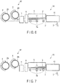
- FIG. 7 illustrates an example in which the coil spring 3 is manufactured by using the short material 2' mounted on the short material mounting portion 9.
- the material 2 more specifically, the short material 2', which is taken out one by one from the short material mounting portion 9 is supplied to the coiling machine 10, and the coil spring 3 is manufactured. Accordingly, this device is suitable for manufacturing of a wide variety of coil springs in small quantities according to the type of the short material 2'.
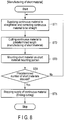
- FIG. 8 is a flowchart showing an example of a short material manufacturing process.
- the short material 2' is manufactured by using the first continuous material 2A or the second continuous material 2B.
- the first continuous material 2A or the second continuous material 2B is supplied to the straightener 7, and is corrected to be straight.
- step ST2 as the continuous material, which is supplied to the cutter 8, is cut to a predetermined length by the cutter 8, the short material 2' is manufactured.
- the short material 2' which is the material cut to the predetermined length, is mounted on the material stand of the short material mounting portion 9 in step ST3.
- step ST4 when it is determined that a predetermined number of short materials 2' have been stocked, supply of the continuous material is stopped in step ST5, and the manufacturing of the short material is finished.
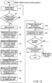
- FIGS. 9 and 10 are flowchart of a case where the coil spring 3 is manufactured by the coil spring manufacturing device 1A.
- FIG. 9 shows steps of selecting the material
- FIG. 10 shows a coil spring manufacturing process.
- step ST10 of FIG. 9 it is determined whether the first continuous material 2A is used or not.
- the process proceeds to step ST11.
- step ST11 the material 2 (the first continuous material 2A) which is placed on the first continuous material mounting portion 4 is supplied to the straightener 7.
- the material 2 is corrected to be straight by the straightener 7 in step ST12, and is supplied to the coiling machine 10 by passing by the cutter 8.
- step ST13 of FIG. 9 it is determined whether the second continuous material 2B is used or not.
- the process proceeds to step ST14.
- step ST14 the material 2 (the second continuous material 2B) which is placed on the second continuous material mounting portion 5 is conveyed to the straightener 7. After the material 2 has been corrected to be straight by the straightener 7 in step ST12, the material 2 is supplied to the coiling machine 10 by passing by the cutter 8.
- step ST13 When it is determined that the short material 2' is to be used in step ST13, the process proceeds to step ST15.
- step ST15 the short material 2' mounted on the short material mounting portion 9 is supplied to the coiling machine 10 one by one via the guide rollers 9a.
- FIG. 10 is a flowchart showing the coil spring manufacturing process.
- a coil spring is manufactured by using the material 2 (the continuous material 2A or 2B, or the short material 2') conveyed to the coiling machine 10.
- the material 2 the continuous material 2A or 2B, or the short material 2'
- a case where the first continuous material 2A is used is referred to as a first continuous material coiling process
- a case where the second continuous material 2B is used is referred to as a second continuous material coiling process
- a case where the short material 2' is used is referred to as a short material coiling process. Note that the structure and the operation of the coiling machine 10 will be described in detail later by referring to FIGS. 11 to 21 .
- step ST21 of FIG. 10 The shape of the coil spring 3 formed by the coiling machine 10 is inspected in step ST21 of FIG. 10 . If the spring shape is rejected, the process proceeds to step ST22, and the coiling condition, etc., is changed. After that, the process returns to step ST20, and the coiling is performed again.
- steps such as a strain relief annealing step (step ST23), a first setting step (step ST24), a shot peening step (step ST25), and a second setting step (step ST26) are carried out. Only one of the first setting step (step ST24) and the second setting step (step ST26) may be carried out.
- the strain relief annealing step (step ST23) is carried out in order to eliminate a processing strain of the coil spring produced by cold working. In step ST23, the coil spring is heated by using a heating furnace, for example.
- step ST27 characteristic of the spring is inspected, and if the characteristic of the spring is acceptable, the process proceeds to step ST28.
- step ST28 when it is determined that a predetermined number of coil springs have been manufactured, coil spring manufacturing is finished. If the predetermined number of coil springs are not obtained, the process returns to step ST20 and the coil spring manufacturing is continued.
- step ST27 if the characteristic of the spring is determined as not being acceptable, the process proceeds to step ST29.
- step ST29 the manufacturing condition, etc., is adjusted, and the process returns to step ST20 to perform the coiling again.
- the present embodiment includes the first continuous material coiling process, the second continuous material coiling process, and the short material coiling process.
- the first continuous material coiling process by supplying the material reeled out from the first continuous material 2A to the coiling machine 10, the coil spring is manufactured.
- the second continuous material coiling process by supplying the material reeled out from the second continuous material 2B to the coiling machine 10, the coil spring is manufactured.
- the short material coiling process by supplying the short material 2' to the coiling machine 10, the coil spring is manufactured.
- FIGS. 11 to 21 The structure and the operation, etc., of the coiling machine 10 will be described by referring to FIGS. 11 to 21 .
- FIG. 11 schematically shows a part of the coiling machine 10.
- the coiling machine 10 comprises a plurality of material feed rollers (feed rollers) 11a and 11b.
- the material feed rollers 11a and 11b move the material 2 of the coil spring in a direction indicated by arrow F (i.e., a direction along an axis X1 of the material 2).
- the material feed rollers 11a and 11b can be moved between a clamping position (a position of sandwiching the material 2) shown in FIG. 11 and an unclamping position (i.e., a position of releasing the material 2) shown in FIG. 14 .
- the coiling machine 10 includes a material guide 12 into which the material 2 is inserted, a first pin 13, and a second pin 14.
- the material 2 bent by the first pin 13 contacts the second pin 14.
- circumferentially continuous grooves 13a and 14a are formed, respectively.
- Each of the first pin 13 and the second pin 14 of the present embodiment is a roller member rotatable about an axis.
- each of the first pin and the second pin may be a pin member which does not rotate.
- the coiling machine 10 includes a pitch tool 15, a cutting tool 16, and a mandrel 17 having a receiving blade 17a.
- the pitch tool 15 is arranged at a front side of a movement direction of the material 2 with respect to the second pin 14. As the material 2 bent by the second pin 14 contacts the pitch tool 15, the coil spring is pitched.
- the cutting tool 16 includes a blade portion 16a. When the cutting tool 16 is moved in a direction indicated by arrow Z1 ( FIG. 11 ) toward the mandrel 17, the material 2 is cut (sheared) between the blade portion 16a and the receiving blade 17a.
- the mandrel 17 can be moved between a first position and a second position by an actuator.
- the first position is an elevated position indicated by a solid line in FIGS. 11 , 14 , 15 , etc.
- the second position is a lowered position indicated by a solid line in FIG. 16 .
- the coiling machine 10 includes a sensor 18 and a material rotation apparatus 20.
- the sensor 18 functions as detection means for detecting a position of a distal end portion 2a ( FIG. 15 ) of the material 2.
- the material rotation apparatus 20 is disposed on an upstream side of the material feed rollers 11a and 11b with respect to the movement direction of the material 2.
- An example of the material rotation apparatus 20 includes a pinch roller unit 21 and a rotation mechanism 25 ( FIG. 12 ).
- the rotation mechanism 25 rotates the pinch roller unit 21 about the axis X1 ( FIG. 11 ) of the material 2.
- the pinch roller unit 21 includes pinch rollers 21a and 21b, an actuator 26 ( FIG. 12 ), a pressure mechanism, etc.
- the pinch rollers 21a and 21b pinch the material 2 radially.
- the actuator 26 rotates the pinch rollers 21a and 21b in a feed direction of the material 2.
- the pressure mechanism urges the pinch rollers 21a and 21b in a direction in which they become close to each other.
- the pinch rollers 21a and 21b can be moved between a clamping position V1 shown by a two-dot chain line in FIG. 11 and an unclamping position V2 shown by a solid line.
- the first pin 13 is disposed at the front side of the movement direction of the material 2 with respect to the distal end 12a of the material guide 12 (i.e., at the downstream side of the movement direction).
- the second pin 14 is disposed at the front side of the movement direction of the material 2 with respect to the first pin 13.
- the material 2 sent out from the distal end 12a of the material guide 12 toward the first pin 13 is bent between the material guide 12 and the first pin 13 with the distal end 12a of the material guide 12 being a substantial bend starting point.
- FIG. 12 is a block diagram showing an electrical structure of the coiling machine 10.
- the coiling machine 10 comprises a central processing unit (CPU) 40 which functions as a controller.
- CPU central processing unit
- ROM read only memory
- RAM random access memory
- communication interface portion 44 a display/operation driver 45, a material feeding driver 46, a first pin moving driver 47, a second pin moving driver 48, a pitch tool driver 49, a cutting tool driver 50, a pinch roller rotation driver 51, a mandrel moving driver 52, a rotation mechanism driver 53, the sensor 18, etc.
- ROM read only memory
- RAM random access memory
- display/operation driver 45 a material feeding driver 46
- first pin moving driver 47 a second pin moving driver 48
- pitch tool driver 49 a cutting tool driver 50
- pinch roller rotation driver 51 a mandrel moving driver 52
- rotation mechanism driver 53 the sensor 18, etc.
- the ROM 42 a program for controlling the CPU 40 and various kinds of fixed data are stored.
- the RAM 43 includes a memory area in which various kinds of data, etc., necessary for forming a coil spring is stored.
- the communication interface portion 44 controls data communication performed with external devices through a communication line (a network).
- the display/operation driver 45 controls a display operation portion 55 comprising a display (a display panel). By operating the display operation portion 55, information necessary for forming the coil spring can be stored in the memories such as the RAM 43.
- the material feeding driver 46 controls a motor 60 for rotating the material feed rollers 11a and 11b.
- the first pin moving driver 47 controls a first pin drive mechanism 61 comprising an actuator for driving the first pin 13.
- the second pin moving driver 48 controls a second pin drive mechanism 62 comprising an actuator for driving the second pin 14.
- the pitch tool driver 49 controls a pitch tool drive mechanism 63 comprising an actuator for driving the pitch tool 15.
- the cutting tool driver 50 controls a cutting tool drive mechanism 64 comprising an actuator for driving the cutting tool 16.
- the pinch roller rotation driver 51 controls the actuator 26 of the pinch roller unit 21.
- the mandrel moving driver 52 controls a mandrel moving actuator 65 for moving the mandrel 17 (up and down, for example).
- the rotation mechanism driver 53 controls an actuator of the rotation mechanism 25.
- the electrical structure including the CPU 40 of the coiling machine 10 includes, for example, a control circuit for controlling the rotation of the rollers 11a and 11b, a control circuit for controlling the pin drive mechanisms 61 and 62, a control circuit for controlling the pitch tool drive mechanism 63, and a control circuit for controlling the cutting tool drive mechanism 64.
- These control circuits function as a control unit 70 which controls the operation or the like of the coiling machine 10.
- the control unit 70 controls the pin drive mechanisms 61 and 62 such that the positions of the first pin 13 and the second pin 14 are changed in accordance with shape data (for example, a coil diameter) of the coil spring that has been input.
- a personal computer 80 can be connected to the control unit 70 of the present embodiment through the communication interface portion 44.
- the personal computer 80 includes a display unit 81 including a display panel, an input operation portion 82 including a keyboard, a pointing device 83 such as a mouse, etc.
- the personal computer 80 includes a storage medium 84 which is removably attached, if necessary.
- the distal end portion shaping operation is an operation which is performed first when starting the forming of the coil spring, that is, the operation of forming the distal end portion 2a of the material 2.
- This distal end portion shaping operation is automated by the CPU 40 based on a computer program stored in the control unit 70 and the shape data for control.
- FIG. 13 is a flowchart showing an example of a function of a computer program stored in the control unit 70. This computer program is activated when performing the distal end portion shaping operation of the coil spring. However, depending on the situation, a part of the distal end portion shaping operation may be carried out manually by a worker.
- FIG. 14 shows the coiling machine 10 before the material 2 is supplied.
- the material feed rollers 11a and 11b wait in a position separated from each other vertically (i.e., in the unclamping position) so as not to obstruct movement of the material 2.
- step S1 of FIG. 13 the material 2 is moved toward the material guide 12 by the pinch rollers 21a and 21b. Consequently, the distal end portion 2a of the material 2 moves forward toward the first pin 13. At this time, the pinch rollers 21a and 21b are moved to the clamping position. The material feed rollers 11a and 11b are moved to the unclamping position. When the material 2 is moved forward toward the material guide 12, the distal end portion 2a of the material 2 projects from the distal end 12a of the material guide 12, as shown in FIG. 15 .
- step S2 of FIG. 13 it is determined whether the distal end portion 2a has reached a predetermined position or not. If the distal end portion 2a has not reached the predetermined position, the process returns to step S1 and the material 2 is further moved forward. For example, when the distal end portion 2a of the material 2 is detected by the detection means (sensor 18), the process proceeds to step S3 and the movement of the material 2 is stopped. At this time, the distal end portion 2a of the material 2 may be stopped at a position projected from the distal end 12a of the material guide 12 by a predetermined distance L1.
- step S4 of FIG. 13 the material feed rollers 11a and 11b are moved to the clamping position.
- the material 2 is sandwiched between the material feed rollers 11a and 11b, and the pinch rollers 21a and 21b are moved to the unclamping position.
- the material 2 is moved by the material feed rollers 11a and 11b.
- step S5 the material 2 sandwiched between the material feed rollers 11a and 11b is moved toward the first pin 13, as shown in FIG. 16 .
- the first pin 13 is driven in a state in which the distal end portion 2a of the material 2 has reached the first pin 13, the distal end portion 2a is bent by the first pin 13.
- the distal end portion 2a of the material 2 is bent in a direction of approaching the mandrel 17 by the first pin 13.
- the mandrel 17 is moved in a direction indicated by arrow Z2 from the first position indicated by a two-dot chain line in FIG. 16 .
- a lower surface of the mandrel 17 is switched from the first position to the second position closest to the distal end 12a of the material guide 12. After the distal end portion 2a of the material 2 has been bent by the first pin 13, the mandrel 17 is moved back to the first position (shown by the two-dot chain line in FIG. 16 ).
- positions of the first pin 13 and the second pin 14 are separated from each other by distance G in a direction along axes X2 and X3 of the pins, as shown in FIG. 17A .
- the distal end portion 2a of the material 2 may be deviated from a groove 14a of the second pin 14.
- the greater distance L2 between the first pin 13 and the second pin 14 becomes, the more it is likely that the distal end portion 2a will be deviated from the groove 14a of the second pin 14. Accordingly, conventionally, the worker needed to correct the orientation of the distal end portion 2a of the material 2 by a jig, etc.
- the second pin 14 is inclined at angle ⁇ 3 ahead of the first pin 13. Also in this case, when the distal end portion 2a of the material 2 is moved forward, the distal end portion 2a may be deviated from the groove 14a of the second pin 14. Accordingly, the worker needed to correct the orientation of the distal end portion 2a of the material 2 by a jig, etc.
- the material 2 is rotated about axis X1 by the pinch rollers 21a and 21b. More specifically, in a state in which the distal end portion 2a of the material 2 is bent by the first pin 13, as shown in FIG. 16 , the material 2 is rotated about axis X1 by the pinch rollers 21a and 21b. At this time, the mandrel 17 is moved to the second position (shown by the two-dot chain). The distal end portion 2a of the material 2 is located between the first pin 13 and the second pin 14.
- steps S6 and S7 of FIG. 13 The above operations are carried out in steps S6 and S7 of FIG. 13 . That is, the material feed rollers 11a and 11b are moved to the unclamping position (shown by two-dot chain line Y in FIG. 16 ). Also, the pinch rollers 21a and 21b are moved to the clamping position (step S6). In this state, by driving the material rotation apparatus 20, the pinch roller unit 21 is rotated such that the distal end portion 2a of the material 2 faces the groove 14a of the second pin 14 (step S7).
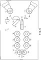
- the distal end portion 2a of the material 2 is inclined by angle ⁇ as shown in FIG. 18 . In this way, when the distal end portion 2a of the material 2 is moved from the first pin 13 toward the second pin 14, the distal end portion 2a can be placed in the groove 14a of the second pin 14.
- step S8 of FIG. 13 the material feed rollers 11a and 11b are moved to the clamping position. Also, the pinch rollers 21a and 21b are moved to the unclamping position. Further, as the material feed rollers 11a and 11b are rotated and the material 2 is moved forward (step S9), the distal end portion 2a enters the groove 14a of the second pin 14 (step S10).
- step S13 of FIG. 13 After the distal-end-side arc portion 2b' of a predetermined shape has been formed, by moving the cutting tool 16 toward the receiving blade 17a as shown in FIG. 21 , a scrap portion 2x at the front end side is cut off (step S13 of FIG. 13 ).
- this cutting operation (step S13) is performed automatically, the worker may perform the cutting operation manually in some cases. In other words, by having the worker check the situation of the coil spring and operate a switch such as a button if no abnormality is found, the cutting tool 16 is operated to cut the scrap portion 2x.
- the distal end portion shaping operation of a coil spring 3 is finished.
- the distal-end-side arc portion 2b' When the scrap portion 2x is cut off, the distal-end-side arc portion 2b' is left.
- the distal-end-side arc portion 2b' constitutes a part of the coil spring (i.e., an end turn portion).
- the coil spring 3 After the above process, by continuously moving the material 2 by the material feed rollers 11a and 11b, the coil spring 3 is formed (coiled). More specifically, the material 2 discharged from the distal end 12a of the material guide 12 is moved toward the second pin 14 via the first pin 13. As the material 2 is formed in an arc shape by the first pin 13 and the second pin 14, an arc portion 2b is formed continuously as shown in FIG. 11 .
- a position of the second pin 14, etc. is controlled.
- a rear end of the coil spring (a front end of a coil spring to be formed next) is cut.
- a continuous material such as the first continuous material 2A or the second continuous material 2B is used, forming of the next one coil spring is performed continuously.
- a coil spring of a number corresponding to the length of the short material 2' (for example, one) is formed.
- a method of shaping a distal end portion of a coil spring of the present embodiment includes the following steps automated by the control unit 70:
- the form such as the structure and arrangement of each of the elements which constitute the coil spring manufacturing device including the continuous material mounting portion on which a continuous material such as a hoop material is mounted, the short material mounting portion, the straightener, and the cutter, may be modified variously if necessary.
- a guide member having a shape different from the guide rollers 9a may be used for the guide means for guiding the material to the coiling machine.
- constituent elements of the coiling machine such as the first pin and the second pin, the pitch tool, and the cutting tool can also be modified variously in embodying the present invention, if necessary.
Landscapes
- Engineering & Computer Science (AREA)
- Mechanical Engineering (AREA)
- Wire Processing (AREA)
Abstract
Description
- The present invention relates to a device for manufacturing a coil spring which manufactures a coil spring by using a long continuous material or a short material which is cut to a predetermined length, and a method for manufacturing the coil spring.
- As a coiling machine suitable for manufacturing coil springs of various shapes in quantity, a coiling machine not having a mandrel is known.
Patent Literature 1 orPatent Literature 2 relates to an example of a coiling machine not having a mandrel. This type of coiling machine bends a material of a coil spring sent out from a distal end of a material guide in an arc shape by a first pin and a second pin, and also pitches the coil spring by a pitch tool. The positions of the first pin and the second pin are controlled based on a computer program stored in a control unit, and control data corresponding to a shape of the coil spring. - A long material (a continuous material) supplied continuously to the coiling machine is wound like a hoop so that it can be conveniently carried or stored. This continuous material is mounted on a reel of a continuous material mounting portion. By rotating the reel, a material of the coil spring is reeled out from the continuous material. The material reeled out is supplied to the coiling machine. By using the continuous material, a coil spring formed of the same type of material can be manufactured in quantity efficiently.
-
- Patent Literature 1:
JP H11-197775 A - Patent Literature 2:
JP 2013-226584 A - In the case of a coiling machine which uses the above-mentioned continuous material, if a material needs to be changed according to the type of the spring (wire diameter or steel type), the continuous material mounted on the continuous material mounting portion must be exchanged. Accordingly, it takes time and manpower to perform the preparation operation for the material exchange. For this reason, manufacturing of a coil spring which uses a hoop material is unsuitable for limited production of diversified products.
- In order to manufacture a wide variety of coil springs in small quantities, using a material cut to a predetermined length in advance (i.e., a short material) is considered. However, in manufacturing a coil spring by the short material, it is necessary to perform a distal end portion shaping operation necessary at the time of starting the coiling for each coil spring. The distal end portion shaping operation has conventionally been performed by a worker who manually operates an actuator. In this manual operation, while a distal end portion of the material is moved toward the first pin, the distal end portion of the material is bent to some degree by moving the first pin. After that, the material is bent in an arc shape while moving the distal end portion of the material toward the second pin. These kinds of works require skill. Furthermore, performing the distal end portion shaping operation for each and every short material is extremely inefficient, and extra caution must be paid for safety. For such reasons, conventional techniques leave room for improvement.
- Accordingly, an object of the present invention is to provide a coil spring manufacturing device capable of efficiently manufacturing a coil spring by using a long continuous material or a short material which is cut to a predetermined length, and a method for manufacturing the coil spring.
- A coil spring manufacturing device according to one embodiment comprises a coiling machine, a continuous material feed portion, a straightener, a cutter, a short material mounting portion, and guide means (for example, a guide roller). The continuous material feed portion supplies a material reeled out from a continuous material wound like a hoop to the coiling machine. The straightener is disposed between the continuous material feed portion and the coiling machine, and corrects the material reeled out from the continuous material to be straight. The cutter is arranged at a downstream side of a movement direction of the material with respect to the straightener, and cuts the material. On the short material mounting portion, a short material cut to a predetermined length is mounted. The guide means supplies the material reeled out from the continuous material feed portion, or the short material taken out from the short material mounting portion to the coiling machine. An example of the continuous material feed portion includes a first continuous material mounting portion and a second continuous material mounting portion. On the first continuous material mounting portion, a first continuous material wound like a hoop is mounted. On the second continuous material mounting portion, a second continuous material wound like a hoop is mounted.
- An example of the coiling machine includes a material feed roller, a material guide, a first pin, a second pin, a pitch tool, a cutting tool, and a control unit. The material feed roller moves the material. The material is inserted into the material guide. The material which is sent out from a distal end of the material guide contacts the first pin. The second pin is disposed at a front side of a movement direction of the material with respect to the first pin. By bending the material between the first pin and the second pin, an arc portion is formed between the first pin and the second pin. The pitch tool is disposed at the front side of the movement direction of the material with respect to the second pin, and the material contacts the pitch tool. The cutting tool is disposed between the second pin and the pitch tool, and cuts the material between the cutting tool and the mandrel.
- The control unit automates a distal end portion shaping operation of the material. The control unit includes means for advancing a distal end portion of the material toward the first pin, and detection means for detecting a position of the distal end portion of the material. Further, the control unit includes means for bending the distal end portion in a direction of approaching the mandrel by the first pin in a state in which the distal end portion reached the first pin, and means for forming a distal-end-side arc portion by bending the distal end portion between the first pin and the second pin.
- According to the present invention, a material reeled out from a long and hooplike continuous material mounted on a long material feed portion, or a short material taken out from the short material mounting portion can be selectively used according to need, and a plurality of kinds of coil springs can be manufactured efficiently.
-
-
FIG. 1 is a plan view schematically showing a coil spring manufacturing device according to a first embodiment. -
FIG. 2 is a plan view schematically showing a coil spring manufacturing device according to a second embodiment. -
FIG. 3 is a plan view of a case where the coil spring manufacturing device shown inFIG. 2 is used, and a coil spring is manufactured by a first continuous material. -
FIG. 4 is a plan view of a case where the coil spring manufacturing device shown inFIG. 2 is used, and a coil spring is manufactured by a second continuous material. -
FIG. 5 is a plan view of a case where the coil spring manufacturing device is used, and a short material is manufactured by the second continuous material. -
FIG. 6 is a plan view of a case where the coil spring manufacturing device is used, and a coil spring is manufactured by the first continuous material and a short material is manufactured by the second continuous material. -
FIG. 7 is a plan view of a case where the coil spring manufacturing device is used, and a coil spring is manufactured by the short material. -
FIG. 8 is a flowchart showing a short material manufacturing process. -
FIG. 9 is a flowchart showing steps of selecting the material. -
FIG. 10 is a flowchart showing a coil spring manufacturing process. -
FIG. 11 is a front view which schematically shows a coiling machine according to one embodiment. -
FIG. 12 is a block diagram showing an electrical structure of the coiling machine. -
FIG. 13 is a flowchart showing an example of a function of a control unit of the coiling machine. -
FIG. 14 is a front view of the coiling machine before a material is supplied. -
FIG. 15 is a front view showing a state in which a distal end portion of a material is projected from a material guide in the coiling machine. -
FIG. 16 is a front view showing a state in which the distal end portion of the material contacts a first pin in the coiling machine. -
FIG. 17A is a side view showing one example of a positional relationship between the first pin and a second pin of the coiling machine. -
FIG. 17B is a side view showing another example of a positional relationship between the first pin and the second pin of the coiling machine. -
FIG. 18 is a cross-sectional view showing one example of a direction in which the distal end portion of the material is rotated. -
FIG. 19 is a front view showing a state in which the distal end portion of the material is moved near the second pin in the coiling machine. -
FIG. 20 is a front view showing a state in which the distal end portion of the material is moved near a pitch tool in the coiling machine. -
FIG. 21 is a front view showing a state in which a scrap portion of the material is cut off in the coiling machine. -
FIG. 1 shows a coilspring manufacturing device 1 according to a first embodiment. The coilspring manufacturing device 1 manufactures acoil spring 3 by forming a rod-shapedmaterial 2 made of spring steel into a helical shape. - The
coil spring 3 is manufactured by forming thematerial 2 spirally at a certain pitch (which may not be constant). The shape of thecoil spring 3 can be various, and a coil diameter and a pitch, for example, may be changed according to the position of turns from an end. The coil spring may be formed in various shapes such as a cylindrical coil spring, a barrel-shaped coil spring, an hourglass coil spring, a tapered coil spring, a variable pitch coil spring, or a coil spring having a negative pitch portion. - The coil
spring manufacturing device 1 according to the present embodiment includes a continuousmaterial mounting portion 4 which functions as a continuous material feed portion W, astraightener 7, a cutter 8 (for example, a cutting grinder), a shortmaterial mounting portion 9, guiderollers 9a which function as guide means, a coilingmachine 10, etc. - On a reel of the continuous
material mounting portion 4, acontinuous material 2A is mounted rotatably about a vertical axis. Thecontinuous material 2A is composed of along material 2 wound like a hoop. Thecontinuous material 2A may be referred to as a hoop material. Thecontinuous material 2A is a heavy load which may weigh several tons in some cases, and the entire length of thematerial 2 which is unwound may be several hundred meters or more. - The
continuous material 2A wound like a hoop has more or less of a bend. For this reason, thematerial 2 which is reeled out from thecontinuous material 2A is corrected to be straight by thestraightener 7. By cutting thecontinuous material 2A corrected to be straight by thecutter 8, a short material 2' of a predetermined length (for example, several meters or so) is obtained. Thecutter 8 is arranged at a downstream side of a movement direction of thematerial 2 with respect to thestraightener 7. The short material 2' obtained by the cutting is mounted on a material stand of the shortmaterial mounting portion 9. - The coil
spring manufacturing device 1 of the present embodiment (FIG. 1 ) manufactures thecoil spring 3 by using thecontinuous material 2A on the continuousmaterial mounting portion 4. Thematerial 2 which is reeled out from thecontinuous material 2A is corrected to be straight by thestraightener 7. Further, thecontinuous material 2A is supplied to the coilingmachine 10 via theguide rollers 9a. The coilingmachine 10 manufactures thecoil spring 3 by forming the suppliedcontinuous material 2A into a helical shape. For example, thematerial 2 which is reeled out from thecontinuous material 2A passes by the cutter 8 (without having thematerial 2 cut), and is supplied to the coilingmachine 10. The structure and the operation of the coilingmachine 10 will be described later. - The coil spring manufacturing device 1 (
FIG. 1 ) can manufacture the short material 2'. The short material 2' can be obtained by cutting thematerial 2, which is reeled out from thecontinuous material 2A on the continuousmaterial mounting portion 4, to a predetermined length by thecutter 8. The short material 2' obtained by the cutting is mounted on the material stand of the shortmaterial mounting portion 9. When thecoil spring 3 is to be manufactured by using the short material 2', the short material 2' is supplied to the coilingmachine 10 one by one from the shortmaterial mounting portion 9. The coilingmachine 10 manufactures thecoil spring 3 by using the short material 2'. Alternatively, the short material may be manufactured by cutting the continuous material by a cutting apparatus provided at a position different from where thecutter 8 is provided. The short material obtained by the cutting is mounted on the shortmaterial mounting portion 9. -
FIG. 2 shows a coilspring manufacturing device 1A according to a second embodiment. The coilspring manufacturing device 1A includes a first continuousmaterial mounting portion 4, a second continuousmaterial mounting portion 5, astraightener 7, acutter 8, a shortmaterial mounting portion 9, guiderollers 9a which function as guide means, a coilingmachine 10, etc. - On the first continuous
material mounting portion 4, a firstcontinuous material 2A (a first hoop material) composed of along material 2 wound like a hoop is mounted. Also on the second continuousmaterial mounting portion 5, a secondcontinuous material 2B (a second hoop material) composed oflong material 2 wound like a hoop is mounted. The firstcontinuous material 2A and the secondcontinuous material 2B may be different from each other in terms of the type (wire diameter or steel type) or the same as each other. The first continuousmaterial mounting portion 4 and the second continuousmaterial mounting portion 5 serve as continuous material feed portions W. -
FIG. 3 illustrates a case where thecoil spring 3 is manufactured from thematerial 2 which is reeled out from the firstcontinuous material 2A in the coilspring manufacturing device 1A shown inFIG. 2 . In this example, thematerial 2 which is reeled out from thecontinuous material 2A on the first continuousmaterial mounting portion 4 is corrected to be straight by thestraightener 7. Further, thematerial 2 is supplied to the coilingmachine 10 via theguide rollers 9a, and thecoil spring 3 is manufactured. Since the second continuousmaterial mounting portion 5 is not used at this time, a spare time is brought about for the second continuousmaterial mounting portion 5. By using this spare time, a continuous material (a hoop material) of a desired wire diameter or steel type can be mounted on the second continuousmaterial mounting portion 5. -
FIG. 4 illustrates a case where thecoil spring 3 is manufactured by using thecontinuous material 2B on the second continuousmaterial mounting portion 5. In this example, thematerial 2 which is reeled out from the secondcontinuous material 2B is corrected to be straight by thestraightener 7. Thematerial 2 is supplied to the coilingmachine 10 via theguide rollers 9a, and thecoil spring 3 is manufactured. Since the first continuousmaterial mounting portion 4 is not used at this time, a spare time is brought about for the first continuousmaterial mounting portion 4. By using this spare time, a continuous material (a hoop material) of a desired wire diameter or steel type can be mounted on the first continuousmaterial mounting portion 4. -
FIG. 3 shows the state in which the coil spring is produced in quantity by using the firstcontinuous material 2A.FIG. 4 shows the state in which the coil spring is produced in quantity by using the secondcontinuous material 2B. When the operation is switched from the state ofFIG. 3 to the state ofFIG. 4 , inFIG. 3 , supply of the firstcontinuous material 2A is stopped. Further, the firstcontinuous material 2A is cut by using thecutter 8. After that, the secondcontinuous material 2B conveyed from the second continuousmaterial mounting portion 5 is supplied to the coilingmachine 10, as shown inFIG. 4 . - Conversely, the operation can be switched from a mass production state of the coil spring using the second
continuous material 2B (FIG. 4 ) to a mass production state of the coil spring using the firstcontinuous material 2A (FIG. 3 ). In this case, supply of the secondcontinuous material 2B is stopped inFIG. 4 , and the secondcontinuous material 2B is cut by using thecutter 8. After that, the firstcontinuous material 2A conveyed from the first continuousmaterial mounting portion 4 is supplied to the coilingmachine 10, as shown inFIG. 3 . - As described above, according to the coil
spring manufacturing device 1A of the present embodiment, a coil spring can be manufactured by alternately switching the continuous materials (the firstcontinuous material 2A and the secondcontinuous material 2B) which are different from each other in their types. More specifically, of the first continuousmaterial mounting portion 4 and the second continuousmaterial mounting portion 5, preparation of the material (an initial setup operation) can be carried out by using the spare time of the continuous material mounting portion not being used. Consequently, two types of coil springs can be manufactured efficiently. - A third continuous
material mounting portion 6 may be provided, as shown by a two-dot chain line inFIG. 2 . Alternatively, four or more continuous material mounting portions may be provided. The necessary continuous material mounting portion is selected from among these continuous material mounting portions and used, and the continuous material is also prepared by using the spare time of the continuous material mounting portion not being used. In this way, more variety of coil springs can be manufactured efficiently, and it is possible to adapt to mass production of a wide variety of springs. -
FIG. 5 shows a short material manufacturing process for manufacturing the short material 2'. In this example, the material 2 (the secondcontinuous material 2B) which is supplied from the second continuousmaterial mounting portion 5 is corrected to be straight by thestraightener 7. As the correctedmaterial 2 is cut by thecutter 8, the short material 2' is manufactured. The short material 2' obtained by the cutting is mounted on the shortmaterial mounting portion 9. -
FIG. 6 shows an example in which thecoil spring 3 is manufactured by using thematerial 2 which is reeled out from thecontinuous material 2A on the first continuousmaterial mounting portion 4, and the short material 2' is manufactured by thematerial 2 which is reeled out from thecontinuous material 2B on the second continuousmaterial mounting portion 5. In this example, as thematerial 2 which is reeled out from the firstcontinuous material 2A is supplied to the coilingmachine 10, thecoil spring 3 is produced in quantity. Simultaneously with the above, thematerial 2, which is reeled out from the secondcontinuous material 2B, is cut to a predetermined length by thecutter 8, and is mounted on the shortmaterial mounting portion 9. -
FIG. 7 illustrates an example in which thecoil spring 3 is manufactured by using the short material 2' mounted on the shortmaterial mounting portion 9. In this example, thematerial 2, more specifically, the short material 2', which is taken out one by one from the shortmaterial mounting portion 9 is supplied to the coilingmachine 10, and thecoil spring 3 is manufactured. Accordingly, this device is suitable for manufacturing of a wide variety of coil springs in small quantities according to the type of the short material 2'. -
FIG. 8 is a flowchart showing an example of a short material manufacturing process. In one example of the short material manufacturing process, the short material 2' is manufactured by using the firstcontinuous material 2A or the secondcontinuous material 2B. For example, in step ST1 ofFIG. 8 , the firstcontinuous material 2A or the secondcontinuous material 2B is supplied to thestraightener 7, and is corrected to be straight. - In step ST2, as the continuous material, which is supplied to the
cutter 8, is cut to a predetermined length by thecutter 8, the short material 2' is manufactured. The short material 2', which is the material cut to the predetermined length, is mounted on the material stand of the shortmaterial mounting portion 9 in step ST3. In step ST4, when it is determined that a predetermined number of short materials 2' have been stocked, supply of the continuous material is stopped in step ST5, and the manufacturing of the short material is finished. - Each of
FIGS. 9 and10 is a flowchart of a case where thecoil spring 3 is manufactured by the coilspring manufacturing device 1A.FIG. 9 shows steps of selecting the material, andFIG. 10 shows a coil spring manufacturing process. In step ST10 ofFIG. 9 , it is determined whether the firstcontinuous material 2A is used or not. When the firstcontinuous material 2A is to be used, the process proceeds to step ST11. In step ST11, the material 2 (the firstcontinuous material 2A) which is placed on the first continuousmaterial mounting portion 4 is supplied to thestraightener 7. Thematerial 2 is corrected to be straight by thestraightener 7 in step ST12, and is supplied to the coilingmachine 10 by passing by thecutter 8. - In step ST13 of
FIG. 9 , it is determined whether the secondcontinuous material 2B is used or not. When the secondcontinuous material 2B is to be used, the process proceeds to step ST14. In step ST14, the material 2 (the secondcontinuous material 2B) which is placed on the second continuousmaterial mounting portion 5 is conveyed to thestraightener 7. After thematerial 2 has been corrected to be straight by thestraightener 7 in step ST12, thematerial 2 is supplied to the coilingmachine 10 by passing by thecutter 8. - When it is determined that the short material 2' is to be used in step ST13, the process proceeds to step ST15. In step ST15, the short material 2' mounted on the short
material mounting portion 9 is supplied to the coilingmachine 10 one by one via theguide rollers 9a. -
FIG. 10 is a flowchart showing the coil spring manufacturing process. In step ST20 ofFIG. 10 , a coil spring is manufactured by using the material 2 (thecontinuous material machine 10. In this specification, a case where the firstcontinuous material 2A is used is referred to as a first continuous material coiling process, and a case where the secondcontinuous material 2B is used is referred to as a second continuous material coiling process. Also, a case where the short material 2' is used is referred to as a short material coiling process. Note that the structure and the operation of the coilingmachine 10 will be described in detail later by referring toFIGS. 11 to 21 . - The shape of the
coil spring 3 formed by the coilingmachine 10 is inspected in step ST21 ofFIG. 10 . If the spring shape is rejected, the process proceeds to step ST22, and the coiling condition, etc., is changed. After that, the process returns to step ST20, and the coiling is performed again. - When it is determined that the spring shape is acceptable in step ST21, steps such as a strain relief annealing step (step ST23), a first setting step (step ST24), a shot peening step (step ST25), and a second setting step (step ST26) are carried out. Only one of the first setting step (step ST24) and the second setting step (step ST26) may be carried out. The strain relief annealing step (step ST23) is carried out in order to eliminate a processing strain of the coil spring produced by cold working. In step ST23, the coil spring is heated by using a heating furnace, for example.
- In step ST27, characteristic of the spring is inspected, and if the characteristic of the spring is acceptable, the process proceeds to step ST28. In step ST28, when it is determined that a predetermined number of coil springs have been manufactured, coil spring manufacturing is finished. If the predetermined number of coil springs are not obtained, the process returns to step ST20 and the coil spring manufacturing is continued.
- In step ST27, if the characteristic of the spring is determined as not being acceptable, the process proceeds to step ST29. In step ST29, the manufacturing condition, etc., is adjusted, and the process returns to step ST20 to perform the coiling again.
- As described above, the present embodiment includes the first continuous material coiling process, the second continuous material coiling process, and the short material coiling process. In the first continuous material coiling process, by supplying the material reeled out from the first
continuous material 2A to the coilingmachine 10, the coil spring is manufactured. In the second continuous material coiling process, by supplying the material reeled out from the secondcontinuous material 2B to the coilingmachine 10, the coil spring is manufactured. In the short material coiling process, by supplying the short material 2' to the coilingmachine 10, the coil spring is manufactured. By switching among the first continuous material coiling process, the second continuous material coiling process, and the short material coiling process as needed, producing a certain type of coil springs in large quantity or producing a wide variety of coil springs in small quantities can be carried out efficiently. - The structure and the operation, etc., of the coiling
machine 10 will be described by referring toFIGS. 11 to 21 . -
FIG. 11 schematically shows a part of the coilingmachine 10. The coilingmachine 10 comprises a plurality of material feed rollers (feed rollers) 11a and 11b. Thematerial feed rollers material 2 of the coil spring in a direction indicated by arrow F (i.e., a direction along an axis X1 of the material 2). Thematerial feed rollers FIG. 11 and an unclamping position (i.e., a position of releasing the material 2) shown inFIG. 14 . - The coiling
machine 10 includes amaterial guide 12 into which thematerial 2 is inserted, afirst pin 13, and asecond pin 14. Thematerial 2 sent out from adistal end 12a of thematerial guide 12 contacts thefirst pin 13 first. Thematerial 2 bent by thefirst pin 13 contacts thesecond pin 14. On outer peripheral portions of thefirst pin 13 and thesecond pin 14, circumferentiallycontinuous grooves first pin 13 and thesecond pin 14 of the present embodiment is a roller member rotatable about an axis. In another embodiment, each of the first pin and the second pin may be a pin member which does not rotate. - The coiling
machine 10 includes apitch tool 15, acutting tool 16, and amandrel 17 having a receivingblade 17a. Thepitch tool 15 is arranged at a front side of a movement direction of thematerial 2 with respect to thesecond pin 14. As thematerial 2 bent by thesecond pin 14 contacts thepitch tool 15, the coil spring is pitched. The cuttingtool 16 includes ablade portion 16a. When thecutting tool 16 is moved in a direction indicated by arrow Z1 (FIG. 11 ) toward themandrel 17, thematerial 2 is cut (sheared) between theblade portion 16a and thereceiving blade 17a. Themandrel 17 can be moved between a first position and a second position by an actuator. The first position is an elevated position indicated by a solid line inFIGS. 11 ,14 ,15 , etc. The second position is a lowered position indicated by a solid line inFIG. 16 . - Further, the coiling
machine 10 includes asensor 18 and amaterial rotation apparatus 20. Thesensor 18 functions as detection means for detecting a position of adistal end portion 2a (FIG. 15 ) of thematerial 2. Thematerial rotation apparatus 20 is disposed on an upstream side of thematerial feed rollers material 2. An example of thematerial rotation apparatus 20 includes apinch roller unit 21 and a rotation mechanism 25 (FIG. 12 ). Therotation mechanism 25 rotates thepinch roller unit 21 about the axis X1 (FIG. 11 ) of thematerial 2. - The
pinch roller unit 21 includespinch rollers FIG. 12 ), a pressure mechanism, etc. Thepinch rollers material 2 radially. Theactuator 26 rotates thepinch rollers material 2. The pressure mechanism urges thepinch rollers pinch rollers FIG. 11 and an unclamping position V2 shown by a solid line. - The
first pin 13 is disposed at the front side of the movement direction of thematerial 2 with respect to thedistal end 12a of the material guide 12 (i.e., at the downstream side of the movement direction). Thesecond pin 14 is disposed at the front side of the movement direction of thematerial 2 with respect to thefirst pin 13. Thematerial 2 sent out from thedistal end 12a of thematerial guide 12 toward thefirst pin 13 is bent between thematerial guide 12 and thefirst pin 13 with thedistal end 12a of thematerial guide 12 being a substantial bend starting point. -
FIG. 12 is a block diagram showing an electrical structure of the coilingmachine 10. The coilingmachine 10 comprises a central processing unit (CPU) 40 which functions as a controller. To theCPU 40, through abus line 41, a read only memory (ROM) 42, a random access memory (RAM) 43, acommunication interface portion 44, a display/operation driver 45, amaterial feeding driver 46, a firstpin moving driver 47, a secondpin moving driver 48, apitch tool driver 49, acutting tool driver 50, a pinchroller rotation driver 51, amandrel moving driver 52, arotation mechanism driver 53, thesensor 18, etc., are connected. - In the
ROM 42, a program for controlling theCPU 40 and various kinds of fixed data are stored. TheRAM 43 includes a memory area in which various kinds of data, etc., necessary for forming a coil spring is stored. Thecommunication interface portion 44 controls data communication performed with external devices through a communication line (a network). The display/operation driver 45 controls adisplay operation portion 55 comprising a display (a display panel). By operating thedisplay operation portion 55, information necessary for forming the coil spring can be stored in the memories such as theRAM 43. - The
material feeding driver 46 controls amotor 60 for rotating thematerial feed rollers pin moving driver 47 controls a firstpin drive mechanism 61 comprising an actuator for driving thefirst pin 13. The secondpin moving driver 48 controls a secondpin drive mechanism 62 comprising an actuator for driving thesecond pin 14. Thepitch tool driver 49 controls a pitchtool drive mechanism 63 comprising an actuator for driving thepitch tool 15. Thecutting tool driver 50 controls a cuttingtool drive mechanism 64 comprising an actuator for driving thecutting tool 16. The pinchroller rotation driver 51 controls theactuator 26 of thepinch roller unit 21. Themandrel moving driver 52 controls amandrel moving actuator 65 for moving the mandrel 17 (up and down, for example). Therotation mechanism driver 53 controls an actuator of therotation mechanism 25. - The electrical structure including the
CPU 40 of the coilingmachine 10 includes, for example, a control circuit for controlling the rotation of therollers pin drive mechanisms tool drive mechanism 63, and a control circuit for controlling the cuttingtool drive mechanism 64. These control circuits function as acontrol unit 70 which controls the operation or the like of the coilingmachine 10. Thecontrol unit 70 controls thepin drive mechanisms first pin 13 and thesecond pin 14 are changed in accordance with shape data (for example, a coil diameter) of the coil spring that has been input. - A
personal computer 80 can be connected to thecontrol unit 70 of the present embodiment through thecommunication interface portion 44. Thepersonal computer 80 includes adisplay unit 81 including a display panel, aninput operation portion 82 including a keyboard, apointing device 83 such as a mouse, etc. Thepersonal computer 80 includes astorage medium 84 which is removably attached, if necessary. - Hereinafter, a distal end portion shaping operation will be described by referring to
FIGS. 13 to 21 . The distal end portion shaping operation is an operation which is performed first when starting the forming of the coil spring, that is, the operation of forming thedistal end portion 2a of thematerial 2. This distal end portion shaping operation is automated by theCPU 40 based on a computer program stored in thecontrol unit 70 and the shape data for control. -
FIG. 13 is a flowchart showing an example of a function of a computer program stored in thecontrol unit 70. This computer program is activated when performing the distal end portion shaping operation of the coil spring. However, depending on the situation, a part of the distal end portion shaping operation may be carried out manually by a worker. -
FIG. 14 shows the coilingmachine 10 before thematerial 2 is supplied. Thematerial feed rollers material 2. - In step S1 of
FIG. 13 , thematerial 2 is moved toward thematerial guide 12 by thepinch rollers distal end portion 2a of thematerial 2 moves forward toward thefirst pin 13. At this time, thepinch rollers material feed rollers material 2 is moved forward toward thematerial guide 12, thedistal end portion 2a of thematerial 2 projects from thedistal end 12a of thematerial guide 12, as shown inFIG. 15 . - In step S2 of
FIG. 13 , it is determined whether thedistal end portion 2a has reached a predetermined position or not. If thedistal end portion 2a has not reached the predetermined position, the process returns to step S1 and thematerial 2 is further moved forward. For example, when thedistal end portion 2a of thematerial 2 is detected by the detection means (sensor 18), the process proceeds to step S3 and the movement of thematerial 2 is stopped. At this time, thedistal end portion 2a of thematerial 2 may be stopped at a position projected from thedistal end 12a of thematerial guide 12 by a predetermined distance L1. - In step S4 of
FIG. 13 , thematerial feed rollers material 2 is sandwiched between thematerial feed rollers pinch rollers material 2 is moved by thematerial feed rollers - In step S5, the
material 2 sandwiched between thematerial feed rollers first pin 13, as shown inFIG. 16 . As thefirst pin 13 is driven in a state in which thedistal end portion 2a of thematerial 2 has reached thefirst pin 13, thedistal end portion 2a is bent by thefirst pin 13. For example, thedistal end portion 2a of thematerial 2 is bent in a direction of approaching themandrel 17 by thefirst pin 13. At this time, themandrel 17 is moved in a direction indicated by arrow Z2 from the first position indicated by a two-dot chain line inFIG. 16 . In other words, a lower surface of themandrel 17 is switched from the first position to the second position closest to thedistal end 12a of thematerial guide 12. After thedistal end portion 2a of thematerial 2 has been bent by thefirst pin 13, themandrel 17 is moved back to the first position (shown by the two-dot chain line inFIG. 16 ). - It is assumed that positions of the
first pin 13 and thesecond pin 14 are separated from each other by distance G in a direction along axes X2 and X3 of the pins, as shown inFIG. 17A . If thedistal end portion 2a of thematerial 2 is moved forward toward thesecond pin 14 in this state, thedistal end portion 2a of thematerial 2 may be deviated from agroove 14a of thesecond pin 14. In particular, the greater distance L2 between thefirst pin 13 and thesecond pin 14 becomes, the more it is likely that thedistal end portion 2a will be deviated from thegroove 14a of thesecond pin 14. Accordingly, conventionally, the worker needed to correct the orientation of thedistal end portion 2a of thematerial 2 by a jig, etc. - As shown in
FIG. 17B , it is assumed that thesecond pin 14 is inclined at angle θ3 ahead of thefirst pin 13. Also in this case, when thedistal end portion 2a of thematerial 2 is moved forward, thedistal end portion 2a may be deviated from thegroove 14a of thesecond pin 14. Accordingly, the worker needed to correct the orientation of thedistal end portion 2a of thematerial 2 by a jig, etc. - In contrast, in the case of the present embodiment, the
material 2 is rotated about axis X1 by thepinch rollers distal end portion 2a of thematerial 2 is bent by thefirst pin 13, as shown inFIG. 16 , thematerial 2 is rotated about axis X1 by thepinch rollers mandrel 17 is moved to the second position (shown by the two-dot chain). Thedistal end portion 2a of thematerial 2 is located between thefirst pin 13 and thesecond pin 14. - The above operations are carried out in steps S6 and S7 of
FIG. 13 . That is, thematerial feed rollers FIG. 16 ). Also, thepinch rollers material rotation apparatus 20, thepinch roller unit 21 is rotated such that thedistal end portion 2a of thematerial 2 faces thegroove 14a of the second pin 14 (step S7). - As the
material 2 is rotated about axis X1, thedistal end portion 2a of thematerial 2 is inclined by angle θ as shown inFIG. 18 . In this way, when thedistal end portion 2a of thematerial 2 is moved from thefirst pin 13 toward thesecond pin 14, thedistal end portion 2a can be placed in thegroove 14a of thesecond pin 14. - In step S8 of
FIG. 13 , thematerial feed rollers pinch rollers material feed rollers material 2 is moved forward (step S9), thedistal end portion 2a enters thegroove 14a of the second pin 14 (step S10). - By moving the
material 2 further by thematerial feed rollers FIG. 19 , thedistal end portion 2a of thematerial 2 is placed between thesecond pin 14 and themandrel 17. Further, while moving thematerial 2, thefirst pin 13 and thesecond pin 14 are driven, and thedistal end portion 2a is bent betweenfirst pin 13 and thesecond pin 14. In this way, a distal-end-side arc portion 2b' is formed as shown inFIG. 20 (steps S11 and S12 ofFIG. 13 ). - After the distal-end-
side arc portion 2b' of a predetermined shape has been formed, by moving thecutting tool 16 toward thereceiving blade 17a as shown inFIG. 21 , ascrap portion 2x at the front end side is cut off (step S13 ofFIG. 13 ). Although this cutting operation (step S13) is performed automatically, the worker may perform the cutting operation manually in some cases. In other words, by having the worker check the situation of the coil spring and operate a switch such as a button if no abnormality is found, the cuttingtool 16 is operated to cut thescrap portion 2x. By way of a series of steps described above, the distal end portion shaping operation of acoil spring 3 is finished. - When the
scrap portion 2x is cut off, the distal-end-side arc portion 2b' is left. The distal-end-side arc portion 2b' constitutes a part of the coil spring (i.e., an end turn portion). After the above process, by continuously moving thematerial 2 by thematerial feed rollers coil spring 3 is formed (coiled). More specifically, thematerial 2 discharged from thedistal end 12a of thematerial guide 12 is moved toward thesecond pin 14 via thefirst pin 13. As thematerial 2 is formed in an arc shape by thefirst pin 13 and thesecond pin 14, anarc portion 2b is formed continuously as shown inFIG. 11 . - After a radius of curvature of the
arc portion 2b is minimized between thefirst pin 13 and thesecond pin 14, the radius of curvature gradually increases as thearc portion 2b approaches thepitch tool 15 because of a springback effect. Accordingly, considering the springback effect, a position of thesecond pin 14, etc., is controlled. When one coil spring is formed, by the operation of thecutting tool 16, a rear end of the coil spring (a front end of a coil spring to be formed next) is cut. When a continuous material such as the firstcontinuous material 2A or the secondcontinuous material 2B is used, forming of the next one coil spring is performed continuously. When the short material 2' is used, a coil spring of a number corresponding to the length of the short material 2' (for example, one) is formed. - As described above, a method of shaping a distal end portion of a coil spring of the present embodiment includes the following steps automated by the control unit 70:
- (1) Moving the
material 2 toward thematerial guide 12; - (2) Detecting the position of the
distal end portion 2a of thematerial 2 which has been sent out from thematerial guide 12; - (3) Moving the
mandrel 17 toward the second position; - (4) Bending the
distal end portion 2a in a direction of approaching themandrel 17 by thefirst pin 13; - (5) Moving the
mandrel 17 to the first position; - (6) Moving the
material feed rollers - (7) Rotating the
material 2 about axis X1 so that thedistal end portion 2a of thematerial 2 is directed toward thegroove 14a of thesecond pin 14; - (8) Moving the
material feed rollers - (9) Moving the
material 2 by thematerial feed rollers distal end portion 2a in thegroove 14a of thesecond pin 14; - (10) Forming the distal-end-
side arc portion 2b' by bending thematerial 2 between thefirst pin 13 and thesecond pin 14; and - (11) Cutting off the
scrap portion 2x ahead of the distal-end-side arc portion 2b' by the cuttingtool 16. - Needless to say, in carrying out the present invention, the form such as the structure and arrangement of each of the elements which constitute the coil spring manufacturing device, including the continuous material mounting portion on which a continuous material such as a hoop material is mounted, the short material mounting portion, the straightener, and the cutter, may be modified variously if necessary. For example, for the guide means for guiding the material to the coiling machine, a guide member having a shape different from the
guide rollers 9a may be used. Further, as a matter of course, constituent elements of the coiling machine such as the first pin and the second pin, the pitch tool, and the cutting tool can also be modified variously in embodying the present invention, if necessary. - 1, 1A··· Coil spring manufacturing device, 2··· Material, 2a··· Distal end portion, W··· Continuous material feed portion, 2A··· First continuous material, 2B··· Second continuous material, 2'··· Short material, 3··· Coil spring, 4··· First continuous material mounting portion, 5··· Second continuous material mounting portion, 6··· Third continuous material mounting portion, 7··· Straightener, 8··· Cutter, 9··· Short material mounting portion, 9a··· Guide roller (guide means), 10··· Coiling machine, 11a, 11b··· Material feed rollers, 12··· Material guide, 12a··· Distal end of material guide, 13··· First pin, 13a··· Groove, 14··· Second pin, 14a··· Groove, 15··· Pitch tool, 16··· Cutting tool, 17··· Mandrel, 18··· Sensor (detection means), 20··· Material rotation apparatus, 21··· Pinch roller unit, 21a, 21b··· Pinch rollers, 70··· Control unit
Claims (5)
- A coil spring manufacturing device comprising:a coiling machine (10);a continuous material feed portion (W) which supplies a material (2) reeled out from a continuous material (2A) (2B) wound like a hoop to the coiling machine (10);a straightener (7) which is disposed between the continuous material feed portion (W) and the coiling machine (10), and is configured to correct the material (2) reeled out from the continuous material (2A) (2B) to be straight;a cutter (8) which is disposed at a downstream side of a movement direction of the material (2) with respect to the straightener (7), and is configured to cut the material (2);a short material mounting portion (9) on which a short material (2') cut to a predetermined length is mounted; andguide means (9a) for supplying the material (2) reeled out from the continuous material feed portion (W) or the short material (2') taken out from the short material mounting portion (9) to the coiling machine (10) .
- The coil spring manufacturing device of Claim 1, wherein the continuous material feed portion (W) includes a first continuous material mounting portion (4) on which a first continuous material (2A) composed of the material (2) wound like a hoop is mounted, and a second continuous material mounting portion (5) on which a second continuous material (2B) composed of the material (2) wound like a hoop is mounted.
- The coil spring manufacturing device of Claim 1, wherein the coiling machine (10) includes:a material feed roller (11a) (11b) which moves the material (2);a material guide (12) into which the material (2) is inserted;a first pin (13) where the material (2) sent out from a distal end of the material guide (12) contacts;a second pin (14) which is disposed at a front side of a movement direction of the material (2) with respect to the first pin (13), and is configured to form an arc portion (2b) between the first pin (13) and the second pin (14) by bending the material (2) between the first pin (13) and the second pin (14);a pitch tool (15) where the material (2) contacts, the pitch tool (15) being disposed at the front side of the movement direction of the material (2) with respect to the second pin (14);a cutting tool (16) which is disposed between the second pin (14) and the pitch tool (15), and is configured to cut the material (2) between the cutting tool (16) and a mandrel (17); anda control unit (70) which automates a distal end portion shaping operation of the material (2), whereinthe control unit (70) comprises:means for advancing a distal end portion (2a) of the material (2) toward the first pin (13);detection means for detecting a position of the distal end portion (2a) of the material (2);means for bending the distal end portion (2a) in a direction of approaching the mandrel (17) by the first pin (13) in a state in which the distal end portion (2a) reached the first pin (13); andmeans for forming a distal-end-side arc portion (2b) by bending the distal end portion (2a) between the first pin (13) and the second pin (14).
- The coil spring manufacturing device of Claim 2, wherein the coiling machine (10) includes:a material feed roller (11a) (11b) which moves the material (2);a material guide (12) into which the material (2) is inserted;a first pin (13) where the material (2) sent out from a distal end of the material guide (12) contacts;a second pin (14) which is disposed at a front side of a movement direction of the material (2) with respect to the first pin (13), and is configured to form an arc portion (2b) between the first pin (13) and the second pin (14) by bending the material (2) between the first pin (13) and the second pin (14);a pitch tool (15) where the material (2) contacts, the pitch tool (15) being disposed at the front side of the movement direction of the material (2) with respect to the second pin (14);a cutting tool (16) which is disposed between the second pin (14) and the pitch tool (15), and is configured to cut the material (2) between the cutting tool (16) and a mandrel (17); anda control unit (70) which automates a distal end portion shaping operation of the material (2), whereinthe control unit (70) comprises:means for advancing a distal end portion (2a) of the material (2) toward the first pin (13);detection means for detecting a position of the distal end portion (2a) of the material (2);means for bending the distal end portion (2a) in a direction of approaching the mandrel (17) by the first pin (13) in a state in which the distal end portion (2a) reached the first pin (13); andmeans for forming a distal-end-side arc portion (2b) by bending the distal end portion (2a) between the first pin (13) and the second pin (14).
- A method for manufacturing a coil spring comprising:a first continuous material coiling process (ST11) (ST20) of manufacturing the coil spring by supplying a material (2) reeled out from a hooplike first continuous material (2A) mounted on a first continuous material mounting portion (4) to a coiling machine (10) ;a second continuous material coiling process (ST14) (ST20) of manufacturing the coil spring by supplying the material (2) reeled out from a hooplike second continuous material (2B) mounted on a second continuous material mounting portion (5) to the coiling machine (10);a short material manufacturing process (ST1-ST5) of manufacturing a short material (2') by cutting the first continuous material (2A) or the second continuous material (2B) to a predetermined length; anda short material coiling process (ST15) (ST20) of manufacturing the coil spring by supplying the short material (2') to the coiling machine (10), whereina plurality of kinds of coil springs are manufactured by switching among the first continuous material coiling process (ST11) (ST20), the second continuous material coiling process (ST14) (ST20), and the short material coiling process (ST15) (ST20).
Applications Claiming Priority (2)
| Application Number | Priority Date | Filing Date | Title |
|---|---|---|---|
| JP2015113849A JP6571994B2 (en) | 2015-06-04 | 2015-06-04 | Coil spring manufacturing apparatus and coil spring manufacturing method |
| PCT/JP2016/061705 WO2016194482A1 (en) | 2015-06-04 | 2016-04-11 | Device for manufacturing coil spring and method for manufacturing coil spring |
Publications (2)
| Publication Number | Publication Date |
|---|---|
| EP3305433A1 true EP3305433A1 (en) | 2018-04-11 |
| EP3305433A4 EP3305433A4 (en) | 2019-01-23 |
Family
ID=57441099
Family Applications (1)
| Application Number | Title | Priority Date | Filing Date |
|---|---|---|---|
| EP16802919.7A Withdrawn EP3305433A4 (en) | 2015-06-04 | 2016-04-11 | HELICOIDAL SPRING MANUFACTURING DEVICE AND HELICOIDAL SPRING MANUFACTURING METHOD |
Country Status (5)
| Country | Link |
|---|---|
| US (1) | US20180071812A1 (en) |
| EP (1) | EP3305433A4 (en) |
| JP (1) | JP6571994B2 (en) |
| CN (1) | CN107614145B (en) |
| WO (1) | WO2016194482A1 (en) |
Families Citing this family (4)
| Publication number | Priority date | Publication date | Assignee | Title |
|---|---|---|---|---|
| TWI692335B (en) * | 2018-09-07 | 2020-05-01 | 黃賢德 | Machine for making variable-pressure coil spring of curtain spring motor |
| JP7258545B2 (en) | 2018-12-28 | 2023-04-17 | 日本発條株式会社 | Coiling machine and manufacturing method of coil spring |
| CN112872251B (en) * | 2020-12-24 | 2023-05-16 | 东莞市杜氏诚发精密弹簧有限公司 | Rotary wire type spring forming machine with automatic wire feeding mechanism |
| CN115532983B (en) * | 2022-10-11 | 2025-05-13 | 中煤建工华南建设有限公司 | An assembled embedded steel bar segment correction machine |
Family Cites Families (15)
| Publication number | Priority date | Publication date | Assignee | Title |
|---|---|---|---|---|
| JPS58135743A (en) * | 1982-02-08 | 1983-08-12 | Hitachi Ltd | Automatic wire processing equipment |
| JPH03189036A (en) * | 1989-12-19 | 1991-08-19 | Kobe Steel Ltd | Manufacture of tapered coil spring |
| JP3172221B2 (en) * | 1991-11-18 | 2001-06-04 | 株式会社東京コイリングマシン製作所 | Manufacturing method of coil spring |
| DE4229294C1 (en) * | 1992-09-02 | 1993-12-16 | Wafios Maschinen Wagner | Wire-shaping machine esp. for mfr. of springs - has wire-clamping rollers turning in either direction together round the wire guide axis and intermittently and programme-controlled |
| JPH081267A (en) * | 1994-06-22 | 1996-01-09 | Daido Steel Co Ltd | Spring material manufacturing method and spring manufacturing method |
| JPH11123497A (en) * | 1997-10-15 | 1999-05-11 | Daido Steel Co Ltd | Feeding equipment for warm and hot working machines |
| DE19748133C2 (en) * | 1997-10-31 | 2000-06-29 | Wafios Maschinen Wagner | Method and device for automatic winding of straight wire to coiled compression springs |
| DE29822163U1 (en) * | 1998-12-11 | 1999-02-11 | Minyu Machinery Corp., Ltd., Taoyuan | Device for the production of wire products |
| JP3805593B2 (en) * | 2000-02-28 | 2006-08-02 | 旭精機工業株式会社 | Coil spring manufacturing method |
| US6910360B2 (en) * | 2001-10-23 | 2005-06-28 | L&P Property Management Company | Multiple wire feed for spring coiling machine and method |
| JP4010829B2 (en) * | 2002-02-21 | 2007-11-21 | 中央発條株式会社 | Coil spring manufacturing method and apparatus |
| JP2004025246A (en) * | 2002-06-26 | 2004-01-29 | Nhk Spring Co Ltd | Method for manufacturing coiled spring having straight inclined axis |
| KR101075323B1 (en) * | 2009-05-19 | 2011-10-19 | 대원강업주식회사 | Manufacturing method of coil spring using helicoid reduction mill |
| JP6012244B2 (en) * | 2012-04-26 | 2016-10-25 | 日本発條株式会社 | COILING MACHINE CONTROL DEVICE AND COIL SPRING MANUFACTURING METHOD |
| DE102013207028B3 (en) * | 2013-04-18 | 2014-06-26 | Wafios Ag | Spring coiling machine with adjustable cutting device |
-
2015
- 2015-06-04 JP JP2015113849A patent/JP6571994B2/en active Active
-
2016
- 2016-04-11 CN CN201680030537.XA patent/CN107614145B/en not_active Expired - Fee Related
- 2016-04-11 EP EP16802919.7A patent/EP3305433A4/en not_active Withdrawn
- 2016-04-11 WO PCT/JP2016/061705 patent/WO2016194482A1/en not_active Ceased
-
2017
- 2017-11-20 US US15/818,316 patent/US20180071812A1/en not_active Abandoned
Also Published As
| Publication number | Publication date |
|---|---|
| JP2017001038A (en) | 2017-01-05 |
| US20180071812A1 (en) | 2018-03-15 |
| JP6571994B2 (en) | 2019-09-04 |
| WO2016194482A1 (en) | 2016-12-08 |
| CN107614145B (en) | 2019-12-27 |
| CN107614145A (en) | 2018-01-19 |
| EP3305433A4 (en) | 2019-01-23 |
Similar Documents
| Publication | Publication Date | Title |
|---|---|---|
| EP1908537B1 (en) | Process and system for production of three-dimensional products from wire | |
| US8393191B2 (en) | Wire forming apparatus | |
| US20180071812A1 (en) | Device for manufacturing coil spring and method for manufacturing coil spring | |
| EP3263242B1 (en) | Coiling machine and method for manufacturing coil springs | |
| TWI625177B (en) | Method for manufacturing springs and spring machine for carrying out the method | |
| KR20170015985A (en) | Bending machine and corresponding method | |
| EP2948257B1 (en) | Apparatus for metal positioning and forming | |
| JP6012244B2 (en) | COILING MACHINE CONTROL DEVICE AND COIL SPRING MANUFACTURING METHOD | |
| KR101757631B1 (en) | Apparatus for bending elongated metal elements, such as metal bars, round pieces or wire, and relative bending method | |
| JP6450640B2 (en) | Coiling machine and coil spring manufacturing method | |
| KR102189749B1 (en) | Drawing and Straightening Apparatus for Metal Wire, and Corresponding Drawing and Straightening Method | |
| KR102404902B1 (en) | Method for performing precise laser cutting on a ribbon sheet and apparatus for performing the method | |
| US11179760B2 (en) | Method of producing a bent part and bending machine for performing the method | |
| US20150075244A1 (en) | Wire forming apparatus | |
| EP3263243B1 (en) | Device for manufacturing coil spring and method for manufacturing coil spring | |
| KR101829324B1 (en) | An apparatus for machining coil-type rebar and a method for operating the same | |
| JP2018140399A (en) | Coil spring production device, and coil spring production method | |
| AU2018315775B2 (en) | Machine and method for bending oblong elements, preferably metal, such as bars, rod, section bars or suchlike | |
| US20090224021A1 (en) | Apparatus and method for processing coiled sheet-like material | |
| JP3397696B2 (en) | Spring forming method | |
| US20250033104A1 (en) | Apparatus and method for bending oblong metal products | |
| JP2009291901A (en) | Cutting device |
Legal Events
| Date | Code | Title | Description |
|---|---|---|---|
| STAA | Information on the status of an ep patent application or granted ep patent |
Free format text: STATUS: THE INTERNATIONAL PUBLICATION HAS BEEN MADE |
|
| PUAI | Public reference made under article 153(3) epc to a published international application that has entered the european phase |
Free format text: ORIGINAL CODE: 0009012 |
|
| STAA | Information on the status of an ep patent application or granted ep patent |
Free format text: STATUS: REQUEST FOR EXAMINATION WAS MADE |
|
| 17P | Request for examination filed |
Effective date: 20171115 |
|
| AK | Designated contracting states |
Kind code of ref document: A1 Designated state(s): AL AT BE BG CH CY CZ DE DK EE ES FI FR GB GR HR HU IE IS IT LI LT LU LV MC MK MT NL NO PL PT RO RS SE SI SK SM TR |
|
| AX | Request for extension of the european patent |
Extension state: BA ME |
|
| DAV | Request for validation of the european patent (deleted) | ||
| DAX | Request for extension of the european patent (deleted) | ||
| A4 | Supplementary search report drawn up and despatched |
Effective date: 20190104 |
|
| RIC1 | Information provided on ipc code assigned before grant |
Ipc: B21F 23/00 20060101ALI20181220BHEP Ipc: B21F 1/02 20060101ALI20181220BHEP Ipc: B21F 11/00 20060101ALI20181220BHEP Ipc: B21F 35/00 20060101AFI20181220BHEP Ipc: B21F 3/04 20060101ALI20181220BHEP |
|
| STAA | Information on the status of an ep patent application or granted ep patent |
Free format text: STATUS: EXAMINATION IS IN PROGRESS |
|
| 17Q | First examination report despatched |
Effective date: 20200518 |
|
| GRAP | Despatch of communication of intention to grant a patent |
Free format text: ORIGINAL CODE: EPIDOSNIGR1 |
|
| STAA | Information on the status of an ep patent application or granted ep patent |
Free format text: STATUS: GRANT OF PATENT IS INTENDED |
|
| INTG | Intention to grant announced |
Effective date: 20210224 |
|
| STAA | Information on the status of an ep patent application or granted ep patent |
Free format text: STATUS: THE APPLICATION IS DEEMED TO BE WITHDRAWN |
|
| 18D | Application deemed to be withdrawn |
Effective date: 20210707 |