EP2948257B1 - Apparatus for metal positioning and forming - Google Patents
Apparatus for metal positioning and forming Download PDFInfo
- Publication number
- EP2948257B1 EP2948257B1 EP14742741.3A EP14742741A EP2948257B1 EP 2948257 B1 EP2948257 B1 EP 2948257B1 EP 14742741 A EP14742741 A EP 14742741A EP 2948257 B1 EP2948257 B1 EP 2948257B1
- Authority
- EP
- European Patent Office
- Prior art keywords
- station
- sheet material
- duct
- making apparatus
- retractable conveyor
- Prior art date
- Legal status (The legal status is an assumption and is not a legal conclusion. Google has not performed a legal analysis and makes no representation as to the accuracy of the status listed.)
- Active
Links
- 239000002184 metal Substances 0.000 title description 18
- 239000000463 material Substances 0.000 claims description 39
- 230000033001 locomotion Effects 0.000 claims description 6
- 238000010008 shearing Methods 0.000 claims description 2
- 239000011800 void material Substances 0.000 claims 2
- 238000005452 bending Methods 0.000 description 12
- 238000000034 method Methods 0.000 description 6
- 230000015572 biosynthetic process Effects 0.000 description 3
- 238000004519 manufacturing process Methods 0.000 description 3
- 238000004826 seaming Methods 0.000 description 3
- 238000005516 engineering process Methods 0.000 description 2
- 238000011144 upstream manufacturing Methods 0.000 description 2
- 238000009423 ventilation Methods 0.000 description 2
- 238000009826 distribution Methods 0.000 description 1
- 238000010438 heat treatment Methods 0.000 description 1
- 239000007769 metal material Substances 0.000 description 1
- 238000005555 metalworking Methods 0.000 description 1
- 230000037361 pathway Effects 0.000 description 1
Images


Classifications
-
- F—MECHANICAL ENGINEERING; LIGHTING; HEATING; WEAPONS; BLASTING
- F24—HEATING; RANGES; VENTILATING
- F24F—AIR-CONDITIONING; AIR-HUMIDIFICATION; VENTILATION; USE OF AIR CURRENTS FOR SCREENING
- F24F13/00—Details common to, or for air-conditioning, air-humidification, ventilation or use of air currents for screening
- F24F13/02—Ducting arrangements
- F24F13/0245—Manufacturing or assembly of air ducts; Methods therefor
-
- B—PERFORMING OPERATIONS; TRANSPORTING
- B21—MECHANICAL METAL-WORKING WITHOUT ESSENTIALLY REMOVING MATERIAL; PUNCHING METAL
- B21D—WORKING OR PROCESSING OF SHEET METAL OR METAL TUBES, RODS OR PROFILES WITHOUT ESSENTIALLY REMOVING MATERIAL; PUNCHING METAL
- B21D35/00—Combined processes according to or processes combined with methods covered by groups B21D1/00 - B21D31/00
-
- B—PERFORMING OPERATIONS; TRANSPORTING
- B21—MECHANICAL METAL-WORKING WITHOUT ESSENTIALLY REMOVING MATERIAL; PUNCHING METAL
- B21D—WORKING OR PROCESSING OF SHEET METAL OR METAL TUBES, RODS OR PROFILES WITHOUT ESSENTIALLY REMOVING MATERIAL; PUNCHING METAL
- B21D39/00—Application of procedures in order to connect objects or parts, e.g. coating with sheet metal otherwise than by plating; Tube expanders
- B21D39/02—Application of procedures in order to connect objects or parts, e.g. coating with sheet metal otherwise than by plating; Tube expanders of sheet metal by folding, e.g. connecting edges of a sheet to form a cylinder
-
- B—PERFORMING OPERATIONS; TRANSPORTING
- B21—MECHANICAL METAL-WORKING WITHOUT ESSENTIALLY REMOVING MATERIAL; PUNCHING METAL
- B21D—WORKING OR PROCESSING OF SHEET METAL OR METAL TUBES, RODS OR PROFILES WITHOUT ESSENTIALLY REMOVING MATERIAL; PUNCHING METAL
- B21D43/00—Feeding, positioning or storing devices combined with, or arranged in, or specially adapted for use in connection with, apparatus for working or processing sheet metal, metal tubes or metal profiles; Associations therewith of cutting devices
- B21D43/02—Advancing work in relation to the stroke of the die or tool
-
- B—PERFORMING OPERATIONS; TRANSPORTING
- B21—MECHANICAL METAL-WORKING WITHOUT ESSENTIALLY REMOVING MATERIAL; PUNCHING METAL
- B21D—WORKING OR PROCESSING OF SHEET METAL OR METAL TUBES, RODS OR PROFILES WITHOUT ESSENTIALLY REMOVING MATERIAL; PUNCHING METAL
- B21D5/00—Bending sheet metal along straight lines, e.g. to form simple curves
- B21D5/01—Bending sheet metal along straight lines, e.g. to form simple curves between rams and anvils or abutments
- B21D5/015—Bending sheet metal along straight lines, e.g. to form simple curves between rams and anvils or abutments for making tubes
-
- B—PERFORMING OPERATIONS; TRANSPORTING
- B21—MECHANICAL METAL-WORKING WITHOUT ESSENTIALLY REMOVING MATERIAL; PUNCHING METAL
- B21D—WORKING OR PROCESSING OF SHEET METAL OR METAL TUBES, RODS OR PROFILES WITHOUT ESSENTIALLY REMOVING MATERIAL; PUNCHING METAL
- B21D5/00—Bending sheet metal along straight lines, e.g. to form simple curves
- B21D5/04—Bending sheet metal along straight lines, e.g. to form simple curves on brakes making use of clamping means on one side of the work
-
- B—PERFORMING OPERATIONS; TRANSPORTING
- B21—MECHANICAL METAL-WORKING WITHOUT ESSENTIALLY REMOVING MATERIAL; PUNCHING METAL
- B21D—WORKING OR PROCESSING OF SHEET METAL OR METAL TUBES, RODS OR PROFILES WITHOUT ESSENTIALLY REMOVING MATERIAL; PUNCHING METAL
- B21D5/00—Bending sheet metal along straight lines, e.g. to form simple curves
- B21D5/06—Bending sheet metal along straight lines, e.g. to form simple curves by drawing procedure making use of dies or forming-rollers, e.g. making profiles
- B21D5/10—Bending sheet metal along straight lines, e.g. to form simple curves by drawing procedure making use of dies or forming-rollers, e.g. making profiles for making tubes
-
- B—PERFORMING OPERATIONS; TRANSPORTING
- B65—CONVEYING; PACKING; STORING; HANDLING THIN OR FILAMENTARY MATERIAL
- B65B—MACHINES, APPARATUS OR DEVICES FOR, OR METHODS OF, PACKAGING ARTICLES OR MATERIALS; UNPACKING
- B65B51/00—Devices for, or methods of, sealing or securing package folds or closures; Devices for gathering or twisting wrappers, or necks of bags
- B65B51/04—Applying separate sealing or securing members, e.g. clips
-
- F—MECHANICAL ENGINEERING; LIGHTING; HEATING; WEAPONS; BLASTING
- F16—ENGINEERING ELEMENTS AND UNITS; GENERAL MEASURES FOR PRODUCING AND MAINTAINING EFFECTIVE FUNCTIONING OF MACHINES OR INSTALLATIONS; THERMAL INSULATION IN GENERAL
- F16L—PIPES; JOINTS OR FITTINGS FOR PIPES; SUPPORTS FOR PIPES, CABLES OR PROTECTIVE TUBING; MEANS FOR THERMAL INSULATION IN GENERAL
- F16L9/00—Rigid pipes
- F16L9/003—Rigid pipes with a rectangular cross-section
-
- Y—GENERAL TAGGING OF NEW TECHNOLOGICAL DEVELOPMENTS; GENERAL TAGGING OF CROSS-SECTIONAL TECHNOLOGIES SPANNING OVER SEVERAL SECTIONS OF THE IPC; TECHNICAL SUBJECTS COVERED BY FORMER USPC CROSS-REFERENCE ART COLLECTIONS [XRACs] AND DIGESTS
- Y10—TECHNICAL SUBJECTS COVERED BY FORMER USPC
- Y10T—TECHNICAL SUBJECTS COVERED BY FORMER US CLASSIFICATION
- Y10T29/00—Metal working
- Y10T29/49—Method of mechanical manufacture
- Y10T29/49826—Assembling or joining
- Y10T29/49908—Joining by deforming
- Y10T29/49936—Surface interlocking
Definitions
- the present invention relates generally to metal working apparatuses and methods, and more particularly, to an apparatus and method for bending sheet metal to form ventilation ducts.
- Box-shaped ducts are extensively used in heating and ventilating systems to distribute heated or cooled air throughout a structure.
- the ducts are commonly formed in sections of predetermined length, which are then connected to form a continuous air distribution duct.
- the material from which the duct sections are formed is sheet metal of the desired gauge fed from a roll or coil of material. As the sheet metal uncoils, it is flattened or straightened to remove the curved set in the material that exists from it being coiled. The sheet metal is then notched along its side edges at predetermined distances where the corners of the duct section will be formed. A shear then cuts the material into blanks of a length necessary to form a finished duct section.
- This notched blank is then moved 90 degrees onto a roll former to form the male and female portions of a lock seam at the opposite ends of the blank.
- the blank is then transferred once again, usually 90 degrees, into a roll former to form the flanges that will provide for connection of the individual duct sections.
- the blank is then transferred to a sheet metal break where three 90 degree bends are made to form the box-shaped duct section.
- a duct making apparatus as defined in claim 1 is provided.
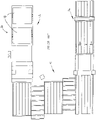
- FIGS. 1-4 are schematic views of known automatic duct making systems 10, 20, 30, 40 for making completed duct sections.
- Each of these systems 10, 20, 30, 40 include a start end 12, a lock seam roll forming section 14 and a finish end 16.
- sheet metal is unwound from large rolls or coils 18.
- the width of the coil 18 determines the length of the completed duct section.
- a duct blank is cut from the coil 18 and advanced in a first direction, e.g., from right to left as shown in FIGS. 1-4 .
- the duct blank is then moved in a second direction substantially perpendicular to the first direction (e.g. from top to bottom or bottom to top as shown in FIGS. 1-4 ) and passes through the roll forming section 14.
- the roll forming section 14 has roll forming stations that are oriented perpendicular to the first direction of movement and form male and female lock seams, respectively, on opposed edges of the duct blank as the duct blank passes therethrough.
- the duct blank is then advanced in a third direction generally parallel to the first direction for subsequent bending and finishing operations prior to arriving at the finish end 16 as a substantially completed duct section.
- the duct blank must be moved in a direction substantially perpendicular to the initial, first direction of movement in order to pass through the roll forming stations of the roll forming section 14 to form the male and female lock seams.
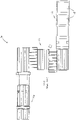
- prior art duct making apparatus typically take a U-shaped configuration, as illustrated by the duct making apparatuses 10, 20 shown in FIGS. 1 and 2 , or a Z-shaped configuration, as illustrated by the duct making apparatuses shown in FIGS. 3 and 4 .
- Both the U-shaped and Z-shaped apparatuses require a considerable amount of floor space due to the need to move the duct blank perpendicularly through the roll forming section 14 and, therefore, are often substantially wider than will fit into many duct manufacturing shops.
- the apparatuses 10, 20, 30, 40 shown in FIGS. 1-4 are approximately 25 feet wide, thereby requiring a large space to accommodate such apparatuses.
- an embodiment of a metal positioning and forming apparatus 100 of the present invention addresses the issue of limited floor space in many duct manufacturing shops, among others, by providing a substantially linear path of travel of the duct blank throughout the apparatus 100, even through the roll forming section that forms the male and female lock seams.
- the metal positioning and forming apparatus 100 includes, at least, a start end 110, a first station 112, a second station 114, a third station 116, and a finish end 118 disposed about a common axis.
- sheet metal of a desired gauge and width is supplied in large rolls or coils 120.
- the sheet metal material from one of the coils 120 is fed by a feeder (not shown) into the first station 112.
- the first station includes a coil straightener 122, a notching section 124 and a bending shear 126, which each may take one of various forms known in the art.
- the coil straightener 122 contains a plurality of rolls that will remove the set in the material caused by it being wound on a coil 120.
- the coil straightener 122 thus straightens the material and feeds the web of material to the notching section 124 that provides corner notches, if needed, for the style of duct section being processed.
- the notching section 124 is programed to notch the side edges of the web of material at predetermined distances where the material will ultimately be bent to form the box-shaped duct section. In other words, the distance between the notches will correspond to the dimensions of the finished duct section.
- the web of material then moves forward, from right to left in FIGS. 5 and 6 , into the bending shear 126 of the first station 112.
- the bending shear 126 bends the leading edge of the web of material utilizing a built in bending die assembly to form a male lock seam, and then proceeds to shear the web of material to make a generally rectangular duct blank flat pattern. Movement of the web of material along the pathway defined by the apparatus 100, from starting end 110 to finish end 118 defines an axis of travel of the web.
- the second station 114 is positioned in line with the first station 112 along a linear direction of travel of the duct blank (i.e., the axis of travel) and includes a retractable conveyor 128, a feed conveyor 130 and a stop and clamp assembly 132.
- the stop and clamp assembly 132 includes a vertically movable clamp 134 and a pivotable stop 136.
- the clamp 134 and stop 136 may be hydraulic, pneumatic or electrically actuated, although any other means for actuating the clamp 134 and stop 136 along their constrained paths of travel known in the art may also be utilized without departing from the broader aspects of the present invention.
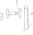
- the stop 136 is selectively rotatable between a raised, pass-through position, as illustrated in FIG. 7 , and a lowered, engaging position, as illustrated in FIG. 8 , as discussed in detail below.
- the clamp 134 is selectively movable between a, raised position in which the clamp 134 is spaced from a duct blank carried on the retractable conveyor 128, as shown in FIG. 9 , and a lowered, clamping position in which the clamp 134 contacts the duct blank and holds it against the retractable conveyor 128, as also discussed in detail below.
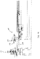
- the retractable conveyor 128 of the second station 114 is linearly movable in the direction of arrow A, as shown in FIG. 12 .
- the retractable conveyor 128 is linearly movable between a first position in close association with the first station 112, as shown in FIG. 15 , and a second position in which the retractable conveyor 128 is spaced from the first station 112, as shown in FIG. 16 .
- the retractable conveyor 128 In operation, as the male lock seam is formed in the leading edge of the duct blank and the duct blank is separated from the web of material, the retractable conveyor 128 is advanced against the direction of travel of the metal web to the extended position shown in FIG. 15 . At the same time, the clamp 134 and stop 136 are moved to their retracted, pass-through positions which allows the duct blank to be advanced downstream. In this position, the retractable conveyor 128 supports the web while it is fed forward and cut to proper length by the bending shear 126, and prevents the web from bowing or hanging down, which could cause jamming. The retractable conveyor 128 remains in this extended position until the duct blank passes the stop and clamp assembly 132, at which time the conveyor 128 retracts and is positioned for a subsequent roll forming operation, as discussed hereinafter.
- the third station 116 includes a female lock seam roll former 140 having a plurality of die pairs.
- the roll former 140 may generally take the form of any roll former commonly known in the art that is utilized to form various style lock seams.
- the roll former 140 may be configured to form any style of lockseam, such as a Pittsburg seam or Snaplock seam, on the trailing edge of the duct blank, as discussed below.
- the roll former 140 is mounted on a laterally traversing frame 142 that is positioned between the first station 112 and second station 114.
- roll former 140 of the third station 116 moves in a direction substantially perpendicular to the axis of travel of the duct blank and engages the trailing edge of the duct blank.
- the roll former 140 travels across the trailing edge of the duct blank, perpendicular to the linear direction of travel of the duct blank, thereby forming a female lock seam.
- Traversing the roll forming head 140 may be accomplished via hydraulic, pneumatic or electrical means, although any other means known in the art may also be utilized without departing from the broader aspects of the present invention.
- the roll former head 140 is selectively movable orthogonal to the axis of travel of the web of material through the apparatus 100.
- the clamps 134 are released and the duct blank is moved linearly down the second station 114 by stationary feed conveyor 130 for additional operations.
- the conveyor 128 retracts (moves to the left in FIG. 12 ) and clamp 134 raises to its pass-through position, allowing the duct blank to proceed downstream through the system reaching feed conveyor 130.
- the roll former 140 is reversed and moves to its original starting position on one side of the apparatus 100.
- the retractable conveyor 128 is then extended to its starting position adjacent to the first station 112 such that the process can be repeated for another duct section.
- the duct blank may proceed forward through the system, reaching feed conveyor 130, transverse connection/ transverse flange roll former 144, brake feed conveyor 146, bending brake 148 and finally exiting end conveyor 150, thus competing a fully automatic cycle generating a completed duct section.
- These subsequent operations may be any operations known in the art of duct section formation, including, but not limited to, the formation of flanges on the ends of the duct section and bending of the duct section to form an enclosed duct.
- the transverse connection roll former 144 may take any form known in the art for forming any type of transverse flange known in the art.
- the apparatus 100 of the present invention is capable of providing all styles of ducting including welded flange and raw edge connections using slide on flange technology in a fully automatic manner.
- the automatic duct making apparatus 100 of the present invention is capable of making any style of ducting by adding any downstream bending/forming stations necessary to achieve the desired style.
- the apparatus 100 may include a computer or programmable logic controller (not shown) and a plurality of switches, sensors and timers that operate in conjunction with one another and according to a set of instructions stored in memory.
- a computer or programmable logic controller not shown
- all of the operational sequences for forming a completed duct section may be carried out automatically under the control of the computer or programmable logic controller in concert with the switches, sensors and timers.
- the apparatus 100 may include locating pins 152 as an alternative means of properly positioning the duct blank on the conveyor 128 for the subsequent female lock seam forming operation.
- the locating pins 152 are pivotally mounted to the second station 114.
- the conveyor 128 retracts to a position that allows the locating pins to pivot downward.
- the conveyor 128 is reversed to transport the duct blank upstream until the locating pins 152 are contacted.
- the pins 152 themselves can be used to complete a circuit confirming that the trailing edge of the duct blank is in correct position.
- holding clamps 134 are extended to clamp the duct blank to the conveyor frame.
- the holding clamps 134 hold the duct blank in proper position during retracting of the locating pins 152 during the roll forming operation, as discussed above.
- FIG. 17 A completed duct section 200 produced by the duct making apparatus 100 of the present invention is shown in FIG. 17 .
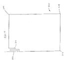
- the completed duct section has a male lock seam 210 formed by the bending shear 126, a female lock seam 212 formed by the transversely movable roll former 140, and a plurality of bends 214 that complete the rectangular duct section.
- the transverse end connections formed by transverse connection roll former 144 are omitted in FIG. 17 .
- the roll former 140 is able to move orthogonally across the trailing edge of the stationary duct blank to form the female lock bend.
- This is in contrast to existing systems which typically put the duct blank in motion and move the blank laterally (i.e., orthogonal to the initial direction of travel) through a stationary roll-forming device to form both the male and female lock seams.
- all of the stations of the apparatus 100 of the present invention may be aligned linearly, as opposed to in a "U" or "Z" configuration as has been heretofore required in the art. With this linear arrangement of stations, the sheet material and the duct blank cut therefrom can be fed entirely linearly throughout the entire apparatus 100, from start end 110 to finish end 118.
- the apparatus 100 of the present invention is much narrower as compared to existing duct making apparatuses configured to handle the same size sheet material.
- the duct making apparatus 100 of the present invention may be approximately half of the width of prior art complete duct fabrication systems.
- the apparatus 100 may be utilized in smaller shops, thereby allowing such smaller shops to compete with larger shops utilizing the wider, existing duct making systems by controlling costs and quality.
- the apparatus 100 of the present invention allows return to previous, more friendly notching and seaming in customary methods allowing minimal openings at the corners of the duct sections. This is desirable for the mechanical contractors because it reduces costs required to treat unnecessary openings in the notched corner area. This is in contrast to many existing systems that form a drive cleat before shearing the duct blank to length and then subsequently form the locks seams causing a substantial notch-back requirement so the cleat isn't crushed during the seaming operation.
Description
- The present invention relates generally to metal working apparatuses and methods, and more particularly, to an apparatus and method for bending sheet metal to form ventilation ducts.
- Box-shaped ducts are extensively used in heating and ventilating systems to distribute heated or cooled air throughout a structure. The ducts are commonly formed in sections of predetermined length, which are then connected to form a continuous air distribution duct. The material from which the duct sections are formed is sheet metal of the desired gauge fed from a roll or coil of material. As the sheet metal uncoils, it is flattened or straightened to remove the curved set in the material that exists from it being coiled. The sheet metal is then notched along its side edges at predetermined distances where the corners of the duct section will be formed. A shear then cuts the material into blanks of a length necessary to form a finished duct section. This notched blank is then moved 90 degrees onto a roll former to form the male and female portions of a lock seam at the opposite ends of the blank. The blank is then transferred once again, usually 90 degrees, into a roll former to form the flanges that will provide for connection of the individual duct sections. When the flanges have been formed, the blank is then transferred to a sheet metal break where three 90 degree bends are made to form the box-shaped duct section.
- As will be readily appreciated, transferring the material both longitudinally and sideways from station to station to form the lock seams and flanges requires a considerable amount of floor space for the equipment, conveyors and transfer tables between the stations. Often times, therefore, large spaces are needed to accommodate the width of existing duct fabricating machines, which increases overhead operating costs.
- There is therefore a need for an improved method and apparatus for forming duct sections which minimizes the amount of floor space required to carry out the complete forming process, and which provides for the forming of duct sections more quickly and efficiently and at a lower cost as compared to existing apparatuses.
- Document
US8171766B1 discloses a duct making apparatus comprising: - a first station configured to accept a formable sheet material, said first station including a first mechanism for forming one of a male lock bend and a female lock seam in a leading edge of said formable sheet material;
- a second station disposed to define an axis of travel of said sheet material from said first station to said second station; and
- It is an object of the present invention to provide an automatic duct making apparatus for metal positioning and forming.
- It is an object of the present invention to provide a duct making apparatus for bending sheet metal to form ventilation ducts.
- It is another object of the present invention to provide a duct making apparatus that is smaller and fits into existing shop areas that are too small for existing duct forming machinery.
- It is another object of the present invention to provide a duct making apparatus that is capable of providing various styles of ducting, including welded flange and raw edge connections using slide on flange technology.
- It is another object of the present invention to provide a duct making apparatus that is narrow in width as compared to existing systems.
- It is another object of the present invention to provide a duct making apparatus that competes with existing wide-footprint systems.
- It is another object of the present invention to provide a duct making apparatus that is configured to move a duct blank workpiece straight forward during forming operations without moving the duct blank sideways or reversing the duct blank in the opposite direction for completing the operations for finishing the duct section.
- It is another object of the present invention to provide a duct making apparatus that substantially eliminates the use of servomotors for positioning of the duct blank during forming operations.
- According to the present invention, a duct making apparatus as defined in claim 1 is provided.
- The present invention will be better understood from reading the following description of non-limiting embodiments, with reference to the attached drawings, wherein below:
-
FIG. 1 is a schematic plan view of a prior art U-shaped duct making apparatus. -
FIG. 2 is a schematic plan view of another prior art U-shaped duct making apparatus. -
FIG. 3 is a schematic plan view of a prior art Z-shaped duct making apparatus. -
FIG. 4 is a schematic plan view of another prior art Z-shaped duct making apparatus. -
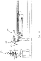
FIG. 5 is a top plan view of an apparatus for metal positioning and forming according to an embodiment of the present invention. -
FIG. 6 is a side elevational view of the apparatus ofFIG. 5 . -
FIG. 7 is side elevational view of a positioning stop of the apparatus ofFIG. 5 , illustrated in its raised, pass through position. -
FIG. 8 is a side elevational view of the positioning stop ofFIG. 7 , illustrating the positioning stop in a lowered, engaging position with a sheet held in a slightly reversed position. -
FIG. 9 is a side elevational view of a conveyor and holding clamp of the apparatus ofFIG. 5 , illustrating the holding clamp in a raised, pass-through position. -
FIG. 10 is a side elevational view of the conveyor and holding clamp ofFIG. 9 , illustrating the holding clamp in a lowered, clamping position. -
FIG. 11 is a side elevational view of a lock seam roll forming device of the apparatus ofFIG. 5 , showing the positing stop ofFIG. 7 in its raised, pass-through position. -
FIG. 12 is a side elevational, expanded view of the conveyor with the retractable conveyor portion in its extended position ready for receiving a sheet as it exits the shear. -
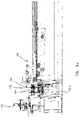
FIG. 13 is another top, plan view of the metal positioning and forming apparatus ofFIG. 5 , showing a more detailed illustration thereof. -
FIG. 14 is a side elevational view of the metal positioning an forming apparatus ofFIG. 5 , showing a more detailed illustration thereof and showing the retractable conveyor in an extended position. -
FIG. 15 is a side elevational view of the metal positioning an forming apparatus ofFIG. 5 , showing a more detailed illustration thereof and showing the retractable conveyor in a retracted position. -
FIG. 16 is a side elevational view of the metal positioning an forming apparatus ofFIG. 5 , showing a more detailed illustration thereof and showing the positioning of the roll forming assembly. -
FIG. 17 is an end view of a duct section manufactured utilizing the apparatus ofFIG. 5 , with both lock seams and bends that complete a rectangular duct section. -
FIGS. 1-4 are schematic views of known automaticduct making systems systems start end 12, a lock seamroll forming section 14 and afinish end 16. As shown therein, with each of thesesystems coils 18. As is well known to those skilled in the art, the width of thecoil 18 determines the length of the completed duct section. - A duct blank is cut from the
coil 18 and advanced in a first direction, e.g., from right to left as shown inFIGS. 1-4 . The duct blank is then moved in a second direction substantially perpendicular to the first direction (e.g. from top to bottom or bottom to top as shown inFIGS. 1-4 ) and passes through theroll forming section 14. Theroll forming section 14 has roll forming stations that are oriented perpendicular to the first direction of movement and form male and female lock seams, respectively, on opposed edges of the duct blank as the duct blank passes therethrough. The duct blank is then advanced in a third direction generally parallel to the first direction for subsequent bending and finishing operations prior to arriving at thefinish end 16 as a substantially completed duct section. - As will be readily appreciated, the duct blank must be moved in a direction substantially perpendicular to the initial, first direction of movement in order to pass through the roll forming stations of the
roll forming section 14 to form the male and female lock seams. As a result, prior art duct making apparatus typically take a U-shaped configuration, as illustrated by the duct makingapparatuses 10, 20 shown inFIGS. 1 and2 , or a Z-shaped configuration, as illustrated by the duct making apparatuses shown inFIGS. 3 and4 . Both the U-shaped and Z-shaped apparatuses, however, require a considerable amount of floor space due to the need to move the duct blank perpendicularly through theroll forming section 14 and, therefore, are often substantially wider than will fit into many duct manufacturing shops. Indeed, theapparatuses FIGS. 1-4 are approximately 25 feet wide, thereby requiring a large space to accommodate such apparatuses. - Turning now to
FIGS. 5 and 6 , an embodiment of a metal positioning and formingapparatus 100 of the present invention addresses the issue of limited floor space in many duct manufacturing shops, among others, by providing a substantially linear path of travel of the duct blank throughout theapparatus 100, even through the roll forming section that forms the male and female lock seams. - As shown therein, the metal positioning and forming
apparatus 100 includes, at least, astart end 110, afirst station 112, asecond station 114, athird station 116, and afinish end 118 disposed about a common axis. At thestart end 110 sheet metal of a desired gauge and width is supplied in large rolls orcoils 120. As is well known to those skilled in the art, the sheet metal material from one of thecoils 120 is fed by a feeder (not shown) into thefirst station 112. The first station includes acoil straightener 122, a notchingsection 124 and a bendingshear 126, which each may take one of various forms known in the art. - The
coil straightener 122 contains a plurality of rolls that will remove the set in the material caused by it being wound on acoil 120. Thecoil straightener 122 thus straightens the material and feeds the web of material to the notchingsection 124 that provides corner notches, if needed, for the style of duct section being processed. The notchingsection 124 is programed to notch the side edges of the web of material at predetermined distances where the material will ultimately be bent to form the box-shaped duct section. In other words, the distance between the notches will correspond to the dimensions of the finished duct section. - The web of material then moves forward, from right to left in
FIGS. 5 and 6 , into the bendingshear 126 of thefirst station 112. The bendingshear 126 bends the leading edge of the web of material utilizing a built in bending die assembly to form a male lock seam, and then proceeds to shear the web of material to make a generally rectangular duct blank flat pattern. Movement of the web of material along the pathway defined by theapparatus 100, from startingend 110 to finishend 118 defines an axis of travel of the web. - With further reference to
FIGS. 5 and 6 , thesecond station 114 is positioned in line with thefirst station 112 along a linear direction of travel of the duct blank (i.e., the axis of travel) and includes aretractable conveyor 128, afeed conveyor 130 and a stop and clampassembly 132. As best shown inFIG. 7 , the stop and clampassembly 132 includes a verticallymovable clamp 134 and apivotable stop 136. Theclamp 134 and stop 136 may be hydraulic, pneumatic or electrically actuated, although any other means for actuating theclamp 134 and stop 136 along their constrained paths of travel known in the art may also be utilized without departing from the broader aspects of the present invention. - The
stop 136 is selectively rotatable between a raised, pass-through position, as illustrated inFIG. 7 , and a lowered, engaging position, as illustrated inFIG. 8 , as discussed in detail below. Likewise, theclamp 134 is selectively movable between a, raised position in which theclamp 134 is spaced from a duct blank carried on theretractable conveyor 128, as shown inFIG. 9 , and a lowered, clamping position in which theclamp 134 contacts the duct blank and holds it against theretractable conveyor 128, as also discussed in detail below. - Importantly, the
retractable conveyor 128 of thesecond station 114 is linearly movable in the direction of arrow A, as shown inFIG. 12 . In particular, theretractable conveyor 128 is linearly movable between a first position in close association with thefirst station 112, as shown inFIG. 15 , and a second position in which theretractable conveyor 128 is spaced from thefirst station 112, as shown inFIG. 16 . - In operation, as the male lock seam is formed in the leading edge of the duct blank and the duct blank is separated from the web of material, the
retractable conveyor 128 is advanced against the direction of travel of the metal web to the extended position shown inFIG. 15 . At the same time, theclamp 134 and stop 136 are moved to their retracted, pass-through positions which allows the duct blank to be advanced downstream. In this position, theretractable conveyor 128 supports the web while it is fed forward and cut to proper length by the bendingshear 126, and prevents the web from bowing or hanging down, which could cause jamming. Theretractable conveyor 128 remains in this extended position until the duct blank passes the stop and clampassembly 132, at which time theconveyor 128 retracts and is positioned for a subsequent roll forming operation, as discussed hereinafter. - In particular, once the trailing edge of the duct blank passes the
stop 136, the stop rotates downward to its engaging position, as illustrated inFIG. 8 . Theconveyor 128 then again reverses direction, moving the duct blank upstream, until the trailing edge of the duct blank contacts stop 136. At this position, clamp 134 is moved into clamping position, shown inFIG. 10 , to clamp the duct blank against theretractable conveyor 128. Once the duct blank is clamped in proper position, stop 136 again rotates to its retracted, pass-through position shown inFIG. 7 . While the figures of the present invention illustrate the utilization of asingle clamp 134 andsingle stop 136, more than oneclamp 134 and stop 136 may be utilized to provide additional clamping and alignment, respectively, without departing from the broader aspects of the present invention. - With reference to
FIGS. 11-13 and16 , thethird station 116 includes a female lock seam roll former 140 having a plurality of die pairs. In the preferred embodiment, the roll former 140 may generally take the form of any roll former commonly known in the art that is utilized to form various style lock seams. In particular, the roll former 140 may be configured to form any style of lockseam, such as a Pittsburg seam or Snaplock seam, on the trailing edge of the duct blank, as discussed below. Importantly, the roll former 140 is mounted on a laterally traversingframe 142 that is positioned between thefirst station 112 andsecond station 114. - Once the duct blank is clamped in position by the
clamp 134, andconveyor 128 is spaced from thefirst station 112, roll former 140 of thethird station 116 moves in a direction substantially perpendicular to the axis of travel of the duct blank and engages the trailing edge of the duct blank. The roll former 140 travels across the trailing edge of the duct blank, perpendicular to the linear direction of travel of the duct blank, thereby forming a female lock seam. Traversing theroll forming head 140 may be accomplished via hydraulic, pneumatic or electrical means, although any other means known in the art may also be utilized without departing from the broader aspects of the present invention. As discussed in detail below, it is an important aspect of the present invention that the rollformer head 140 is selectively movable orthogonal to the axis of travel of the web of material through theapparatus 100. - After forming the female lock seam in the trailing edge of the duct blank, the
clamps 134 are released and the duct blank is moved linearly down thesecond station 114 bystationary feed conveyor 130 for additional operations. In particular, once seaming is complete, theconveyor 128 retracts (moves to the left inFIG. 12 ) and clamp 134 raises to its pass-through position, allowing the duct blank to proceed downstream through the system reachingfeed conveyor 130. Once the trail edge of the duct blank is fully onconveyor 130, the roll former 140 is reversed and moves to its original starting position on one side of theapparatus 100. Theretractable conveyor 128 is then extended to its starting position adjacent to thefirst station 112 such that the process can be repeated for another duct section. - As alluded to above, additional operations may be carried out downstream after formation of the male and female lock seams. In an embodiment, the duct blank may proceed forward through the system, reaching
feed conveyor 130, transverse connection/ transverse flange roll former 144,brake feed conveyor 146, bendingbrake 148 and finally exitingend conveyor 150, thus competing a fully automatic cycle generating a completed duct section. These subsequent operations may be any operations known in the art of duct section formation, including, but not limited to, the formation of flanges on the ends of the duct section and bending of the duct section to form an enclosed duct. - In particular, the transverse connection roll former 144 may take any form known in the art for forming any type of transverse flange known in the art. Moreover, the
apparatus 100 of the present invention is capable of providing all styles of ducting including welded flange and raw edge connections using slide on flange technology in a fully automatic manner. As will be readily appreciated, the automaticduct making apparatus 100 of the present invention is capable of making any style of ducting by adding any downstream bending/forming stations necessary to achieve the desired style. - In an embodiment, the
apparatus 100 may include a computer or programmable logic controller (not shown) and a plurality of switches, sensors and timers that operate in conjunction with one another and according to a set of instructions stored in memory. In particular, all of the operational sequences for forming a completed duct section may be carried out automatically under the control of the computer or programmable logic controller in concert with the switches, sensors and timers. - With further reference to
FIGS. 13-16 , in an embodiment, theapparatus 100 may include locatingpins 152 as an alternative means of properly positioning the duct blank on theconveyor 128 for the subsequent female lock seam forming operation. As shown therein, the locating pins 152 are pivotally mounted to thesecond station 114. During operation, theconveyor 128 retracts to a position that allows the locating pins to pivot downward. Once in the down position, theconveyor 128 is reversed to transport the duct blank upstream until the locating pins 152 are contacted. In an embodiment, thepins 152 themselves can be used to complete a circuit confirming that the trailing edge of the duct blank is in correct position. Other sensing means known in the art may also be utilized without departing from the broader aspects of the present invention. Once the duct blank is confirmed to be in the proper position, holdingclamps 134 are extended to clamp the duct blank to the conveyor frame. The holding clamps 134 hold the duct blank in proper position during retracting of the locating pins 152 during the roll forming operation, as discussed above. - A completed
duct section 200 produced by theduct making apparatus 100 of the present invention is shown inFIG. 17 . As shown therein the completed duct section has amale lock seam 210 formed by the bendingshear 126, afemale lock seam 212 formed by the transversely movable roll former 140, and a plurality ofbends 214 that complete the rectangular duct section. The transverse end connections formed by transverse connection roll former 144 are omitted inFIG. 17 . - As will be readily appreciated, by mounting the roll former 140 on a laterally
movable frame 142, the roll former 140 is able to move orthogonally across the trailing edge of the stationary duct blank to form the female lock bend. This is in contrast to existing systems which typically put the duct blank in motion and move the blank laterally (i.e., orthogonal to the initial direction of travel) through a stationary roll-forming device to form both the male and female lock seams. As the need to move the duct blank sideways is obviated by the provision of the transversely movable roll former 140, all of the stations of theapparatus 100 of the present invention may be aligned linearly, as opposed to in a "U" or "Z" configuration as has been heretofore required in the art. With this linear arrangement of stations, the sheet material and the duct blank cut therefrom can be fed entirely linearly throughout theentire apparatus 100, fromstart end 110 to finishend 118. - As a result of this configuration, the
apparatus 100 of the present invention is much narrower as compared to existing duct making apparatuses configured to handle the same size sheet material. In particular, in an embodiment, theduct making apparatus 100 of the present invention may be approximately half of the width of prior art complete duct fabrication systems. As will be readily appreciated, because of this smaller and narrower footprint, theapparatus 100 may be utilized in smaller shops, thereby allowing such smaller shops to compete with larger shops utilizing the wider, existing duct making systems by controlling costs and quality. - With existing systems, there is a need to move various sizes and gauges of sheet material through side motions to form the lock seams, which typically requires a variety of guiding and setting requirements to move the sheets squarely and accurately without jams, run off conditions or buckling difficulties. With the
apparatus 100 of the present invention, however, these problems are eliminated because the sheet material/ duct blank moves in a straight line from start to finish, allowing simple conveyance. - In addition to the above, the
apparatus 100 of the present invention allows return to previous, more friendly notching and seaming in customary methods allowing minimal openings at the corners of the duct sections. This is desirable for the mechanical contractors because it reduces costs required to treat unnecessary openings in the notched corner area. This is in contrast to many existing systems that form a drive cleat before shearing the duct blank to length and then subsequently form the locks seams causing a substantial notch-back requirement so the cleat isn't crushed during the seaming operation.
Claims (6)
- A duct making apparatus (100), comprising:a first station (112) configured to accept a formable sheet material, said first station (112) including a first mechanism for forming one of a male lock bend and a female lock seam in a leading edge of said formable sheet material;a second station (114) disposed to define an axis of travel of said sheet material from said first station (112) to said second station (114); and- a third station (116) arranged to form the other of said male lock bend and said female lock seam on a trailing edge of said formable sheet material characterized in that:- said second station (114) has a retractable conveyor (128), said retractable conveyor (128) being selectively movable from a first position in which said retractable conveyor (128) is in close association with said first station (112), to a second position in which said retractable conveyor (128) is spaced apart from said first station (112) forming thereby a void between said first station (112) and said second station (114); said third station (116) includes a roll forming assembly, said roll forming assembly being selectively movable in a direction substantially orthogonal to moving direction of said retractable conveyor (128) and substantially orthogonal to said axis of travel of said sheet material, said third station (116) being further arranged to form the other of said male lock bend and said female lock seam on the trailing edge of said formable sheet material when said retractable conveyor (128) is in said second position and when a portion of said roll forming assembly is selectively inserted into said void via said movement of the roll forming assembly in said direction substantially orthogonal to moving direction of said retractable conveyor (128).
- The duct making apparatus of claim 1, wherein:
said retractable conveyor (128), when in said first position, supports an underside of said sheet material. - The duct making apparatus of claim 1, wherein: said second station (114) further includes a positioning stop (136), said positioning stop (136) being selectively movable between a pass-through position in which said sheet material is permitted to pass by said positioning stop (136), and an engaging position in which said trailing edge of said sheet material contacts said positioning stop (136); wherein said positioning stop (136) is configured to position said sheet material in alignment with said roll forming assembly.
- The duct making apparatus of claim 3, wherein: said second station (114) further includes at least one clamp mechanism, said clamp mechanism (132) being selectively movable between a pass-though position in which said clamp mechanism (132) is spaced from said sheet material, and a clamping position in which said clamp mechanism (132) contacts said sheet material.
- The duct making apparatus of claim 1, wherein: said first station (112) further includes a coil straightener (122) for straightening said sheet material received from a coil (129) and a notching section (124) configured to provide notches in corners of said sheet material.
- The duct making apparatus of claim 1, wherein:
said first station (112) includes a mechanism for shearing said sheet material to form a generally rectangular duct blank flat pattern.
Applications Claiming Priority (3)
| Application Number | Priority Date | Filing Date | Title |
|---|---|---|---|
| US201361756226P | 2013-01-24 | 2013-01-24 | |
| US201361766207P | 2013-02-19 | 2013-02-19 | |
| PCT/US2014/012899 WO2014116920A1 (en) | 2013-01-24 | 2014-01-24 | Method and apparatus for metal positioning and forming |
Publications (3)
| Publication Number | Publication Date |
|---|---|
| EP2948257A1 EP2948257A1 (en) | 2015-12-02 |
| EP2948257A4 EP2948257A4 (en) | 2017-01-18 |
| EP2948257B1 true EP2948257B1 (en) | 2022-06-29 |
Family
ID=51206662
Family Applications (1)
| Application Number | Title | Priority Date | Filing Date |
|---|---|---|---|
| EP14742741.3A Active EP2948257B1 (en) | 2013-01-24 | 2014-01-24 | Apparatus for metal positioning and forming |
Country Status (4)
| Country | Link |
|---|---|
| US (3) | US9459019B2 (en) |
| EP (1) | EP2948257B1 (en) |
| FR (1) | FR3103719B1 (en) |
| WO (1) | WO2014116920A1 (en) |
Families Citing this family (10)
| Publication number | Priority date | Publication date | Assignee | Title |
|---|---|---|---|---|
| WO2015089329A1 (en) | 2013-12-12 | 2015-06-18 | Capital Hardware Supply, Inc. | Corner seal device for ductwork for conditioned air and method of assembly of such ductwork to prevent air leaks |
| CN105171428A (en) * | 2015-09-23 | 2015-12-23 | 浙江新跃电气有限公司 | Automatic plate bending device of power distribution cabinet |
| CN108787751B (en) * | 2018-05-21 | 2020-02-07 | 南京钢铁股份有限公司 | Production control method for wide-width thin-specification super stainless steel plate coil of single-stand steckel mill |
| US11213878B2 (en) | 2019-03-01 | 2022-01-04 | Hvac Inventors/Systemation, Inc. | Apparatus and method for forming duct flanges and duct work |
| CN110711807A (en) * | 2019-11-14 | 2020-01-21 | 无锡中舜精密钣金有限公司 | Continuous combined type bending process for door shell sheet metal part |
| US11364533B2 (en) * | 2020-03-28 | 2022-06-21 | Sewon Precision Industry Co., Ltd. | Transfer pressing apparatus and method |
| US20220003340A1 (en) * | 2020-07-06 | 2022-01-06 | Mestek Machinery, Inc. | System and method for forming a full engagement male lock in a ductline |
| CN112139312A (en) * | 2020-09-14 | 2020-12-29 | 贵州航天天马机电科技有限公司 | Aluminum alloy semi-circular pipe profiling one-step forming equipment and method |
| US11685568B2 (en) * | 2021-03-22 | 2023-06-27 | Infinity Machine & Engineering Corp. | Adjustable packaging machine |
| CN114918631B (en) * | 2022-06-22 | 2024-03-26 | 云南通变电器配件有限公司 | Continuous forming system and forming method for section bar for energy-saving power distribution cabinet |
Family Cites Families (6)
| Publication number | Priority date | Publication date | Assignee | Title |
|---|---|---|---|---|
| US3982457A (en) * | 1975-03-21 | 1976-09-28 | Berry Robert N | Notching machine |
| TWI261025B (en) * | 2004-09-27 | 2006-09-01 | Bobst Sa | Assembly device of plate elements for a processing machine |
| US7650729B2 (en) * | 2006-09-08 | 2010-01-26 | Tipper Tie, Inc. | Telescoping conveyor mechanisms that cooperate with packaging systems having clippers and related methods |
| US8171766B1 (en) * | 2007-11-30 | 2012-05-08 | Active Systems, Inc. | Pass through inline seam rollformer |
| US8499604B2 (en) | 2008-10-01 | 2013-08-06 | Mestek Machinery, Inc. | Duct making apparatus and method |
| US8458884B2 (en) * | 2009-08-06 | 2013-06-11 | Mestek Machinery, Inc. | Method for forming a duct |
-
2014
- 2014-01-24 WO PCT/US2014/012899 patent/WO2014116920A1/en active Application Filing
- 2014-01-24 EP EP14742741.3A patent/EP2948257B1/en active Active
- 2014-01-24 US US14/163,038 patent/US9459019B2/en active Active
-
2016
- 2016-09-07 US US15/258,124 patent/US10527314B2/en active Active
-
2019
- 2019-12-03 US US16/701,768 patent/US11333389B2/en active Active
-
2020
- 2020-12-03 FR FR2012651A patent/FR3103719B1/en active Active
Also Published As
| Publication number | Publication date |
|---|---|
| US20140202225A1 (en) | 2014-07-24 |
| FR3103719B1 (en) | 2023-06-23 |
| US11333389B2 (en) | 2022-05-17 |
| US20200103137A1 (en) | 2020-04-02 |
| US9459019B2 (en) | 2016-10-04 |
| EP2948257A1 (en) | 2015-12-02 |
| FR3103719A1 (en) | 2021-06-04 |
| WO2014116920A1 (en) | 2014-07-31 |
| EP2948257A4 (en) | 2017-01-18 |
| US10527314B2 (en) | 2020-01-07 |
| US20160377314A1 (en) | 2016-12-29 |
Similar Documents
| Publication | Publication Date | Title |
|---|---|---|
| US11333389B2 (en) | Method and apparatus for metal positioning and forming | |
| CA2060032C (en) | Method and apparatus for forming box-shaped sheet metal ducts | |
| CN103801627B (en) | For the manufacturing installation of heat-exchanger fin | |
| JP3478891B2 (en) | Manufacturing method of band blade | |
| US2098989A (en) | Apparatus for and process of making hollow bodies | |
| US9393638B2 (en) | System and method for plasma cutting sheet metal in an automated coil-line machine | |
| JP2007525326A (en) | Production line and method for forming profiles | |
| KR102404902B1 (en) | Method for performing precise laser cutting on a ribbon sheet and apparatus for performing the method | |
| EP3007837B1 (en) | Assembly for and method of marking and cutting wires, and machine comprising said assembly | |
| US20090224021A1 (en) | Apparatus and method for processing coiled sheet-like material | |
| US7451629B2 (en) | Spiral pipe machine | |
| TWI763901B (en) | Machine and method for bending oblong elements, preferably metal, such as bars, rod, section bars or suchlike | |
| AU2014240278B2 (en) | Apparatus and method for inserting angle plates and closing duct seams | |
| KR102234153B1 (en) | Method and equipment for manipulating metal working members | |
| KR920008139Y1 (en) | Plate bending apparatus | |
| KR0177011B1 (en) | Pipe bending machine | |
| CN112770852A (en) | Method for manufacturing complex curvature tubular products such as ELM coils | |
| US20230249237A1 (en) | Apparatus and method for working oblong metal products | |
| JPH06210344A (en) | Method and device for producing tubular body | |
| ITPD990038A1 (en) | SPECIAL MOLDING PLANT DEDICATED TO THE PRODUCTION OF PERCASSET SIDES ON TWO INDEPENDENT LINES ONE RIGHT AND ONE LEFT | |
| PL218641B1 (en) | Line for the manufacture of perforated profiles |
Legal Events
| Date | Code | Title | Description |
|---|---|---|---|
| PUAI | Public reference made under article 153(3) epc to a published international application that has entered the european phase |
Free format text: ORIGINAL CODE: 0009012 |
|
| 17P | Request for examination filed |
Effective date: 20150720 |
|
| AK | Designated contracting states |
Kind code of ref document: A1 Designated state(s): AL AT BE BG CH CY CZ DE DK EE ES FI FR GB GR HR HU IE IS IT LI LT LU LV MC MK MT NL NO PL PT RO RS SE SI SK SM TR |
|
| AX | Request for extension of the european patent |
Extension state: BA ME |
|
| DAX | Request for extension of the european patent (deleted) | ||
| A4 | Supplementary search report drawn up and despatched |
Effective date: 20161216 |
|
| RIC1 | Information provided on ipc code assigned before grant |
Ipc: B21D 39/02 20060101ALI20161212BHEP Ipc: B21D 5/01 20060101ALI20161212BHEP Ipc: B21B 15/00 20060101AFI20161212BHEP Ipc: B21D 43/02 20060101ALI20161212BHEP |
|
| STAA | Information on the status of an ep patent application or granted ep patent |
Free format text: STATUS: EXAMINATION IS IN PROGRESS |
|
| 17Q | First examination report despatched |
Effective date: 20181220 |
|
| STAA | Information on the status of an ep patent application or granted ep patent |
Free format text: STATUS: EXAMINATION IS IN PROGRESS |
|
| STAA | Information on the status of an ep patent application or granted ep patent |
Free format text: STATUS: EXAMINATION IS IN PROGRESS |
|
| GRAP | Despatch of communication of intention to grant a patent |
Free format text: ORIGINAL CODE: EPIDOSNIGR1 |
|
| STAA | Information on the status of an ep patent application or granted ep patent |
Free format text: STATUS: GRANT OF PATENT IS INTENDED |
|
| INTG | Intention to grant announced |
Effective date: 20220225 |
|
| GRAS | Grant fee paid |
Free format text: ORIGINAL CODE: EPIDOSNIGR3 |
|
| GRAA | (expected) grant |
Free format text: ORIGINAL CODE: 0009210 |
|
| STAA | Information on the status of an ep patent application or granted ep patent |
Free format text: STATUS: THE PATENT HAS BEEN GRANTED |
|
| AK | Designated contracting states |
Kind code of ref document: B1 Designated state(s): AL AT BE BG CH CY CZ DE DK EE ES FI FR GB GR HR HU IE IS IT LI LT LU LV MC MK MT NL NO PL PT RO RS SE SI SK SM TR |
|
| REG | Reference to a national code |
Ref country code: GB Ref legal event code: FG4D |
|
| REG | Reference to a national code |
Ref country code: CH Ref legal event code: EP |
|
| REG | Reference to a national code |
Ref country code: AT Ref legal event code: REF Ref document number: 1500964 Country of ref document: AT Kind code of ref document: T Effective date: 20220715 |
|
| REG | Reference to a national code |
Ref country code: IE Ref legal event code: FG4D |
|
| REG | Reference to a national code |
Ref country code: DE Ref legal event code: R096 Ref document number: 602014084157 Country of ref document: DE |
|
| REG | Reference to a national code |
Ref country code: LT Ref legal event code: MG9D |
|
| PG25 | Lapsed in a contracting state [announced via postgrant information from national office to epo] |
Ref country code: SE Free format text: LAPSE BECAUSE OF FAILURE TO SUBMIT A TRANSLATION OF THE DESCRIPTION OR TO PAY THE FEE WITHIN THE PRESCRIBED TIME-LIMIT Effective date: 20220629 Ref country code: NO Free format text: LAPSE BECAUSE OF FAILURE TO SUBMIT A TRANSLATION OF THE DESCRIPTION OR TO PAY THE FEE WITHIN THE PRESCRIBED TIME-LIMIT Effective date: 20220929 Ref country code: LT Free format text: LAPSE BECAUSE OF FAILURE TO SUBMIT A TRANSLATION OF THE DESCRIPTION OR TO PAY THE FEE WITHIN THE PRESCRIBED TIME-LIMIT Effective date: 20220629 Ref country code: HR Free format text: LAPSE BECAUSE OF FAILURE TO SUBMIT A TRANSLATION OF THE DESCRIPTION OR TO PAY THE FEE WITHIN THE PRESCRIBED TIME-LIMIT Effective date: 20220629 Ref country code: GR Free format text: LAPSE BECAUSE OF FAILURE TO SUBMIT A TRANSLATION OF THE DESCRIPTION OR TO PAY THE FEE WITHIN THE PRESCRIBED TIME-LIMIT Effective date: 20220930 Ref country code: FI Free format text: LAPSE BECAUSE OF FAILURE TO SUBMIT A TRANSLATION OF THE DESCRIPTION OR TO PAY THE FEE WITHIN THE PRESCRIBED TIME-LIMIT Effective date: 20220629 Ref country code: BG Free format text: LAPSE BECAUSE OF FAILURE TO SUBMIT A TRANSLATION OF THE DESCRIPTION OR TO PAY THE FEE WITHIN THE PRESCRIBED TIME-LIMIT Effective date: 20220929 |
|
| REG | Reference to a national code |
Ref country code: NL Ref legal event code: MP Effective date: 20220629 |
|
| REG | Reference to a national code |
Ref country code: AT Ref legal event code: MK05 Ref document number: 1500964 Country of ref document: AT Kind code of ref document: T Effective date: 20220629 |
|
| PG25 | Lapsed in a contracting state [announced via postgrant information from national office to epo] |
Ref country code: RS Free format text: LAPSE BECAUSE OF FAILURE TO SUBMIT A TRANSLATION OF THE DESCRIPTION OR TO PAY THE FEE WITHIN THE PRESCRIBED TIME-LIMIT Effective date: 20220629 Ref country code: LV Free format text: LAPSE BECAUSE OF FAILURE TO SUBMIT A TRANSLATION OF THE DESCRIPTION OR TO PAY THE FEE WITHIN THE PRESCRIBED TIME-LIMIT Effective date: 20220629 |
|
| PG25 | Lapsed in a contracting state [announced via postgrant information from national office to epo] |
Ref country code: NL Free format text: LAPSE BECAUSE OF FAILURE TO SUBMIT A TRANSLATION OF THE DESCRIPTION OR TO PAY THE FEE WITHIN THE PRESCRIBED TIME-LIMIT Effective date: 20220629 |
|
| PG25 | Lapsed in a contracting state [announced via postgrant information from national office to epo] |
Ref country code: SM Free format text: LAPSE BECAUSE OF FAILURE TO SUBMIT A TRANSLATION OF THE DESCRIPTION OR TO PAY THE FEE WITHIN THE PRESCRIBED TIME-LIMIT Effective date: 20220629 Ref country code: SK Free format text: LAPSE BECAUSE OF FAILURE TO SUBMIT A TRANSLATION OF THE DESCRIPTION OR TO PAY THE FEE WITHIN THE PRESCRIBED TIME-LIMIT Effective date: 20220629 Ref country code: RO Free format text: LAPSE BECAUSE OF FAILURE TO SUBMIT A TRANSLATION OF THE DESCRIPTION OR TO PAY THE FEE WITHIN THE PRESCRIBED TIME-LIMIT Effective date: 20220629 Ref country code: PT Free format text: LAPSE BECAUSE OF FAILURE TO SUBMIT A TRANSLATION OF THE DESCRIPTION OR TO PAY THE FEE WITHIN THE PRESCRIBED TIME-LIMIT Effective date: 20221031 Ref country code: ES Free format text: LAPSE BECAUSE OF FAILURE TO SUBMIT A TRANSLATION OF THE DESCRIPTION OR TO PAY THE FEE WITHIN THE PRESCRIBED TIME-LIMIT Effective date: 20220629 Ref country code: EE Free format text: LAPSE BECAUSE OF FAILURE TO SUBMIT A TRANSLATION OF THE DESCRIPTION OR TO PAY THE FEE WITHIN THE PRESCRIBED TIME-LIMIT Effective date: 20220629 Ref country code: AT Free format text: LAPSE BECAUSE OF FAILURE TO SUBMIT A TRANSLATION OF THE DESCRIPTION OR TO PAY THE FEE WITHIN THE PRESCRIBED TIME-LIMIT Effective date: 20220629 |
|
| PG25 | Lapsed in a contracting state [announced via postgrant information from national office to epo] |
Ref country code: PL Free format text: LAPSE BECAUSE OF FAILURE TO SUBMIT A TRANSLATION OF THE DESCRIPTION OR TO PAY THE FEE WITHIN THE PRESCRIBED TIME-LIMIT Effective date: 20220629 Ref country code: IS Free format text: LAPSE BECAUSE OF FAILURE TO SUBMIT A TRANSLATION OF THE DESCRIPTION OR TO PAY THE FEE WITHIN THE PRESCRIBED TIME-LIMIT Effective date: 20221029 |
|
| REG | Reference to a national code |
Ref country code: DE Ref legal event code: R097 Ref document number: 602014084157 Country of ref document: DE |
|
| PG25 | Lapsed in a contracting state [announced via postgrant information from national office to epo] |
Ref country code: AL Free format text: LAPSE BECAUSE OF FAILURE TO SUBMIT A TRANSLATION OF THE DESCRIPTION OR TO PAY THE FEE WITHIN THE PRESCRIBED TIME-LIMIT Effective date: 20220629 |
|
| PG25 | Lapsed in a contracting state [announced via postgrant information from national office to epo] |
Ref country code: DK Free format text: LAPSE BECAUSE OF FAILURE TO SUBMIT A TRANSLATION OF THE DESCRIPTION OR TO PAY THE FEE WITHIN THE PRESCRIBED TIME-LIMIT Effective date: 20220629 |
|
| PGFP | Annual fee paid to national office [announced via postgrant information from national office to epo] |
Ref country code: IE Payment date: 20230119 Year of fee payment: 10 Ref country code: FR Payment date: 20230124 Year of fee payment: 10 Ref country code: CZ Payment date: 20230117 Year of fee payment: 10 Ref country code: CH Payment date: 20230124 Year of fee payment: 10 |
|
| PLBE | No opposition filed within time limit |
Free format text: ORIGINAL CODE: 0009261 |
|
| STAA | Information on the status of an ep patent application or granted ep patent |
Free format text: STATUS: NO OPPOSITION FILED WITHIN TIME LIMIT |
|
| PGFP | Annual fee paid to national office [announced via postgrant information from national office to epo] |
Ref country code: TR Payment date: 20230123 Year of fee payment: 10 Ref country code: IT Payment date: 20230120 Year of fee payment: 10 Ref country code: GB Payment date: 20230119 Year of fee payment: 10 Ref country code: DE Payment date: 20230123 Year of fee payment: 10 Ref country code: BE Payment date: 20230119 Year of fee payment: 10 |
|
| 26N | No opposition filed |
Effective date: 20230330 |
|
| PG25 | Lapsed in a contracting state [announced via postgrant information from national office to epo] |
Ref country code: SI Free format text: LAPSE BECAUSE OF FAILURE TO SUBMIT A TRANSLATION OF THE DESCRIPTION OR TO PAY THE FEE WITHIN THE PRESCRIBED TIME-LIMIT Effective date: 20220629 |
|
| PG25 | Lapsed in a contracting state [announced via postgrant information from national office to epo] |
Ref country code: LU Free format text: LAPSE BECAUSE OF NON-PAYMENT OF DUE FEES Effective date: 20230124 |
|
| PGFP | Annual fee paid to national office [announced via postgrant information from national office to epo] |
Ref country code: IE Payment date: 20240119 Year of fee payment: 11 |