EP3305154B1 - Aspirateur de type séparé deux en un portatif à tige, pourvu d'un dispositif indépendant de séparation poussière-air et de stockage de poussière - Google Patents
Aspirateur de type séparé deux en un portatif à tige, pourvu d'un dispositif indépendant de séparation poussière-air et de stockage de poussière Download PDFInfo
- Publication number
- EP3305154B1 EP3305154B1 EP15893911.6A EP15893911A EP3305154B1 EP 3305154 B1 EP3305154 B1 EP 3305154B1 EP 15893911 A EP15893911 A EP 15893911A EP 3305154 B1 EP3305154 B1 EP 3305154B1
- Authority
- EP
- European Patent Office
- Prior art keywords
- dust
- dust collecting
- main device
- push rod
- rod
- Prior art date
- Legal status (The legal status is an assumption and is not a legal conclusion. Google has not performed a legal analysis and makes no representation as to the accuracy of the status listed.)
- Active
Links
- 239000000428 dust Substances 0.000 title claims description 177
- 238000000926 separation method Methods 0.000 title claims description 20
- 230000013011 mating Effects 0.000 claims description 3
- 238000004140 cleaning Methods 0.000 description 9
- 238000001914 filtration Methods 0.000 description 6
- 238000005516 engineering process Methods 0.000 description 4
- 239000002245 particle Substances 0.000 description 4
- 230000007547 defect Effects 0.000 description 1
- 230000008030 elimination Effects 0.000 description 1
- 238000003379 elimination reaction Methods 0.000 description 1
- 238000009434 installation Methods 0.000 description 1
- 238000012986 modification Methods 0.000 description 1
- 230000004048 modification Effects 0.000 description 1
Images


Classifications
-
- A—HUMAN NECESSITIES
- A47—FURNITURE; DOMESTIC ARTICLES OR APPLIANCES; COFFEE MILLS; SPICE MILLS; SUCTION CLEANERS IN GENERAL
- A47L—DOMESTIC WASHING OR CLEANING; SUCTION CLEANERS IN GENERAL
- A47L9/00—Details or accessories of suction cleaners, e.g. mechanical means for controlling the suction or for effecting pulsating action; Storing devices specially adapted to suction cleaners or parts thereof; Carrying-vehicles specially adapted for suction cleaners
- A47L9/10—Filters; Dust separators; Dust removal; Automatic exchange of filters
- A47L9/102—Dust separators
-
- A—HUMAN NECESSITIES
- A47—FURNITURE; DOMESTIC ARTICLES OR APPLIANCES; COFFEE MILLS; SPICE MILLS; SUCTION CLEANERS IN GENERAL
- A47L—DOMESTIC WASHING OR CLEANING; SUCTION CLEANERS IN GENERAL
- A47L5/00—Structural features of suction cleaners
- A47L5/12—Structural features of suction cleaners with power-driven air-pumps or air-compressors, e.g. driven by motor vehicle engine vacuum
- A47L5/22—Structural features of suction cleaners with power-driven air-pumps or air-compressors, e.g. driven by motor vehicle engine vacuum with rotary fans
- A47L5/225—Convertible suction cleaners, i.e. convertible between different types thereof, e.g. from upright suction cleaners to sledge-type suction cleaners
-
- A—HUMAN NECESSITIES
- A47—FURNITURE; DOMESTIC ARTICLES OR APPLIANCES; COFFEE MILLS; SPICE MILLS; SUCTION CLEANERS IN GENERAL
- A47L—DOMESTIC WASHING OR CLEANING; SUCTION CLEANERS IN GENERAL
- A47L5/00—Structural features of suction cleaners
- A47L5/12—Structural features of suction cleaners with power-driven air-pumps or air-compressors, e.g. driven by motor vehicle engine vacuum
- A47L5/22—Structural features of suction cleaners with power-driven air-pumps or air-compressors, e.g. driven by motor vehicle engine vacuum with rotary fans
- A47L5/24—Hand-supported suction cleaners
-
- A—HUMAN NECESSITIES
- A47—FURNITURE; DOMESTIC ARTICLES OR APPLIANCES; COFFEE MILLS; SPICE MILLS; SUCTION CLEANERS IN GENERAL
- A47L—DOMESTIC WASHING OR CLEANING; SUCTION CLEANERS IN GENERAL
- A47L9/00—Details or accessories of suction cleaners, e.g. mechanical means for controlling the suction or for effecting pulsating action; Storing devices specially adapted to suction cleaners or parts thereof; Carrying-vehicles specially adapted for suction cleaners
- A47L9/02—Nozzles
- A47L9/06—Nozzles with fixed, e.g. adjustably fixed brushes or the like
- A47L9/0606—Nozzles with fixed, e.g. adjustably fixed brushes or the like rigidly anchored brushes, combs, lips or pads
-
- A—HUMAN NECESSITIES
- A47—FURNITURE; DOMESTIC ARTICLES OR APPLIANCES; COFFEE MILLS; SPICE MILLS; SUCTION CLEANERS IN GENERAL
- A47L—DOMESTIC WASHING OR CLEANING; SUCTION CLEANERS IN GENERAL
- A47L9/00—Details or accessories of suction cleaners, e.g. mechanical means for controlling the suction or for effecting pulsating action; Storing devices specially adapted to suction cleaners or parts thereof; Carrying-vehicles specially adapted for suction cleaners
- A47L9/10—Filters; Dust separators; Dust removal; Automatic exchange of filters
-
- A—HUMAN NECESSITIES
- A47—FURNITURE; DOMESTIC ARTICLES OR APPLIANCES; COFFEE MILLS; SPICE MILLS; SUCTION CLEANERS IN GENERAL
- A47L—DOMESTIC WASHING OR CLEANING; SUCTION CLEANERS IN GENERAL
- A47L9/00—Details or accessories of suction cleaners, e.g. mechanical means for controlling the suction or for effecting pulsating action; Storing devices specially adapted to suction cleaners or parts thereof; Carrying-vehicles specially adapted for suction cleaners
- A47L9/28—Installation of the electric equipment, e.g. adaptation or attachment to the suction cleaner; Controlling suction cleaners by electric means
- A47L9/2868—Arrangements for power supply of vacuum cleaners or the accessories thereof
- A47L9/2884—Details of arrangements of batteries or their installation
Definitions
- the present application relates to the field of suction cleaners, and in particular to a rod handheld two-in-one separated-type suction cleaner having an independent dust-air separation and dust storage device.
- Suction cleaners as daily-use articles, are widely used for cleaning of indoors and outdoors.
- Conventional suction cleaners may be classified, by shape, into a horizontal suction cleaner, a vertical suction cleaner and a portable suction cleaner, and so on.
- the horizontal suction cleaner includes a fan which is used for generating vacuum and connected to a ground brush through components such as a hose and a long connecting tube, and etc..
- a main device is placed on the ground and can be dragged to move, and the hose is handheld by a person to clean the ground.
- such a suction cleaner has a large volume and a lot of components and is complicated to operate.
- the fan is connected to the ground brush through the hose, which results in a long connection distance and a large energy loss.
- the ground brush is made integrally with a machine head. In use, the cleaning of the ground may just be performed by simply pushing the whole machine.
- This kind of suction cleaner is applicable for a large area of cleaning, and mainly facilitates the cleaning of the ground, however, it is very inconvenient for cleaning of a wall surface, a sofa, a window, a desktop and an electrical appliance, and so on.
- a bypass hose is generally added to the machine head for connection to a variety of common hairbrushes and suction ports. This type of suction cleaner has a large volume, a high cost and is inconvenient for dust suction.
- Cid Patent CN 201110369036.3 discloses a vertical suction cleaner, which includes a chassis, a body, a dust collecting mechanism and a motor.
- the dust collecting mechanism is arranged on the body and includes a fan, a filter and a dust cup, and the dust cup is arranged on an upper end face of a main body of a fan seat.
- This vertical suction cleaner has a large dust collection capacity, but cannot be used in a separated mode, which causes a cleaning operation to be inconvenient.
- a portable suction cleaner for example a rod handheld separated-type suction cleaner, may be considered as a combination of a vertical suction cleaner and a handheld suction cleaner.
- the portable suction cleaner is more flexible in usage than the vertical suction cleaner and is used in a wider range than the handheld suction cleaner.
- this type of suction cleaner mainly includes a ground brush, a push rod and a main device.
- the ground brush and the main device are connected to a front end and a back end of the push rod respectively, and the main device is detachable for being used independently as a hand-held suction cleaner, which facilitates cleaning of articles such as a wall surface, a sofa, a windowsill, a desktop and an electrical appliance.
- the main device, the ground brush and the push rod may be combined to form a ground mopping suction cleaner.
- this kind of suction cleaner has a small main device for being portable, which causes the suction cleaner to have a small dust collecting device and a low dust collection capacity, and such a suction cleaner is not practical in a dusty place.
- only one dust collecting device is provided in the handheld suction cleaner, thus, large particles of dust entering into the dust collecting device is prone to cause blockage.
- only one dust collecting device since only one dust collecting device is provided, it has to make the main device large in volume and large in weight, which causes inconvenience in taking and using.
- WO2014001489 A1 discloses a combination of a compact vacuum cleaner, which comprises a first dust extractor device with a first dust collector, a fan for generating a stream of suction air through the first dust extractor device and an electric motor for driving the fan, and a vacuum cleaner housing which comprises a second dust collector.
- the compact vacuum cleaner can be inserted into the vacuum cleaner housing comprising the second dust collector and the first and second dust collectors can be removed together as a combined unit from the vacuum cleaner housing.
- the invention also relates to a compact vacuum cleaner of this type and to a correspondingly designed vacuum cleaner housing. This allows filter performance to be improved during the operation of the compact vacuum cleaner as a unit together with the vacuum cleaner housing, without the need for significant additional handling requirements for the elimination of the extracted dust.
- a rod handheld two-in-one separated-type suction cleaner is provided according to the present application. Every two of a main device, a push rod and a ground brush of the suction cleaner may be separated and assembled, and the suction cleaner has a first dust collecting device and a second dust collecting device, thus not only increasing the dust collection capacity, but also preventing blockage, and further avoiding the handheld suction cleaner to be large in weight and large in volume for handholding and the handheld suction cleaner to be detached to dump dust.
- a rod handheld two-in-one separated-type suction cleaner provided according to the present invention is defined in claim 1.
- the rod handheld two-in-one separated-type suction cleaner includes a main device, a push rod and a ground brush.
- the main device is a handheld suction cleaner and the push rod is a hollow rod. Every two of the main device, the push rod and the ground brush may be separated and assembled.
- the rod handheld two-in-one separated-type suction cleaner further includes an independent dust-air separation and dust storage device which is detachably arranged between the ground brush and the main device.
- the independent dust-air separation and dust storage device forms a first dust collecting device and a built-in dust collecting device of the main device forms a second dust collecting device.
- filtered secondary dust air is formed after initial dust air passing through the first dust collecting device, and at least a portion of dust in the initial dust air is collected in the first dust collecting device and then the secondary dust air enters the second dust collecting device for being filtered.
- the first dust collecting device includes a detachable dust collecting cup and a detachable connector.
- a rear portion of the ground brush is provided with a securing opening movably cooperating with a lower end of the connector.
- An upper end of the connector is provided with a securing opening into which one end of the push rod is inserted to be secured.
- a dust-air separation device is provided in the dust collecting cup.
- Initial dust air forms filtered secondary dust air after passing through the dust collecting cup, and at least a portion of dust in the initial dust air is collected in the dust collecting cup.
- the dust collecting cup may be taken down independently to dump dust.
- the dust collecting cup is vertically or laterally secured to the connector, and the dust collecting cup has openings which are in communication with a suction port of the main device and the connector respectively.
- the dust collecting cup is arranged on the ground brush, and the dust collecting cup has openings which are in communication with the ground brush and the connector respectively.
- a lock catch means is arranged on a rod body of the push rod and a corresponding hasp means is arranged on a machine body of the main device.
- the main device and the push rod are secured through the lock catch means and the hasp means.
- the main device and the push rod are combined, forming an extended-type handheld suction cleaner.
- each of two ends of the push rod there is an opening on each of two ends of the push rod.
- Each of an opening on one end of the push rod and the suction port of the main device has a mating structure, and the opening on the one end is butt-joined with the suction port of the main device.
- the rod body of the push rod and the air duct of the main device form a third integral air duct.
- An opening on the other end of the push rod forms a suction port of the third integral air duct.
- the main device may be powered by being charged or being connected to a power supply via a plug.
- the present application has the following advantages.
- the rod handheld separated-type suction cleaner is provided with the independent dust-air separation and dust storage device, thus increasing the dust collection capacity, and enabling the dust collecting cup to be taken down independently to dump dust.
- the main device may be small in volume and light in weight, facilitating the taking of the main device.
- the main device, the push rod and the ground brush of the suction cleaner may be separated and assembled, and the main device may be used independently as a suction cleaner, also may be connected to a push rod for use as an extended suction cleaner.
- the suction cleaner may be a chargeable suction cleaner, and may operate without a power line in use, which is more convenient.
- the conventional horizontal or vertical suction cleaner has a large dust collection capacity, it cannot be used in a separated mode and is inconvenient to clean.
- the conventional rod handheld separated-type suction cleaner though, can be used separately, has a low dust collection capacity and is prone to be blocked due to limitation of space of a machine body, besides, the main device has a large volume and weight, causing inconvenience in taking and using.
- FIG. 2 shows a rod handheld two-in-one separated-type suction cleaner having an independent dust-air separation and dust storage device according to a first embodiment of the present application.
- the suction cleaner includes a main device 1, a push rod 2 and a ground brush 3.
- the main device 1 is a handheld suction cleaner and the push rod 2 is a hollow rod. Every two of the main device 1, the push rod 2 and the ground brush 3 may be separated and assembled.
- the rod handheld separated-type suction cleaner further includes a first dust collecting device 4, that is, an independent dust-air separation and dust storage device.
- the first dust collecting device 4 includes a dust collecting cup 5 and a connector 6, both of which may be detachably arranged between the ground brush and the main device.
- a built-in dust collecting device of the main device 1 forms a second dust collecting device 7.
- a rear portion of the ground brush is provided with a securing opening movably cooperating with a lower end of the connector 6 of the first dust collecting device.
- An upper end of the connector 6 is provided with a securing opening into which a front end of the push rod 2 is inserted to be secured, thereby the main device 1, the push rod 2, the ground brush 3 and the first dust collecting device may be used in combination to form a ground mopping suction cleaner.
- a distal end of the push rod 2 is provided with a push rod handle 8, and the push rod handle 8 is provided with a first power supply switch (not illustrated in the figure) which controls on and off of the ground mopping suction cleaner according to this embodiment.
- Figures 3 to 6 are schematic views showing flow directions of air flow in the case that the dust collecting cup 5 is secured in different positions according to the first embodiment of the present application, and directions of arrows in the figures indicate the flow directions of the air flow in an air duct.
- the first dust collecting device 4 may be detachably secured to the ground brush 3 at any position and by any form, and the first dust collecting device 4 is provided with a channel in communication with the ground brush 3.
- the dust collecting cup 5 is vertically secured to the connector 6, and there is a first opening in communication with the connector 6 at a side of the dust collecting cup 5 and a second opening in connection with a suction port of the main device 1 and communicating with the suction port at an upper end of the dust collecting cup 5.
- the dust collecting cup 5 rotates by 90 degrees to be laterally secured to the connector 6, and there are openings on both of an upper side and a lower side of the dust collecting cup 5, which are in communication with the connector 6 and the suction port of the main device 1 respectively, and the suction port of the main device 1 is inserted into a corresponding opening of the dust collecting cup 5 and communicates with it.
- the dust collecting cup 5 is in a lateral direction, and there is a first opening in communication with the connector 6 in a left side of the dust collecting cup 5 and a second opening in connection and communication with the suction port of the main device 1 in an upper side of the dust collecting cup 5.
- the dust collecting cup 5 is directly secured to the ground brush 3 and is provided with two openings which are in communication with the ground brush 3 and the connector 6 respectively, and in this case the suction port of the main device is in communication with the connector 6.
- An air duct of the ground brush 3, an air duct of the first dust collecting device 4 and an air duct of the main device 1 form a first integral air duct in the above several securing manners according to this embodiment.
- the first dust collecting device 4 may alternatively include only a dust collecting cup 5 with the connector dispensed, that is, the dust collecting cup 5 is directly attached to the push rod 2 in any form.
- the dust collecting cup 5 is provided with two openings which are in communication with the push rod 2 and the main device 1 respectively.
- the dust collecting cup 5 is directly secured to the ground brush 3 and is provided with openings which are in communication with the ground brush 3 and the push rod 2 respectively, while the suction port of the main device is in communication with the push rod, thereby the air duct of the ground brush 3, an air duct of the push rod 2, an air duct of the dust collecting cup 5 and the air duct of the main device 1 form an integral air duct.
- the ground mopping suction cleaner can have a small volume and a light weight and be more convenient.
- the dust collecting cup 5 in each example may be taken down independently to dump dust.
- a dust-air separation device is arranged in each of the first dust collecting device 4 and the second dust collecting device 7. After initial dust air passing through the first dust collecting device 4, filtered secondary dust air is formed, and at least a portion of dust in the initial dust air is collected in the first dust collecting device 4, specifically, in the dust collecting cup 5. Thereafter, secondary dust air enters the second dust collecting device 7 for being filtered.
- each of the first dust collecting cup 5 and the second dust collecting device 7 includes two portions -- a front portion and a back portion, which are connected by a snap-fit manner to form a sealed space for storing suctioned dust.
- Each of the dust collecting cup 5 and the second dust collecting device 7 is provided with a dust collecting device separation button to separate the front portion and the back portion of the corresponding dust collecting devices. The front portion and the back portion of a dust collecting device may be separated from each other to remove dust within the dust collecting device in the case that its separation button is pressed.
- the main device 1 as a whole is attached to the push rod 2, that is, a lock catch means is provided on a rod body of the push rod 2 and a corresponding hasp means is provided on the body of the main device.
- the main device and the push rod are secured through the lock catch means and the hasp means.
- the lock catch means and the hasp means can be released and locked by providing an unlocking button for controlling the installation and separation of the main device and the push rod.
- a bottom of the ground brush 3 is provided with a roller.
- an operation mode of the suction cleaner is a ground mopping mode according to the first embodiment
- the ground brush sucks dust.
- the ground mopping type dust suction may just be performed by simply gripping a handle at the distal end of the handheld push rod 2.
- Figure 7 is a schematic view showing the dust collecting cup 5, which is taken down independently to dump the dust, according to the first embodiment of the present application.
- the dust is sucked by the ground brush 3, and the dust passes through the first dust collecting device 4 and the second collection device 7 in the listed sequence.
- the first dust collecting device 4 is added, that is, a primary filtration is added and the dust collecting cup 5 may filter the dust independently and dump the dust independently, the main device 1 can be cleaned without being removed from the suction cleaner.
- the primary filtration remaining dust enters the second dust collecting device 7 in the main device 1 for being the secondarily filtered. Since a vast majority of large particles of dust is filtered in the primary filtration, it is difficult for a minor portion of remaining small particles of dust to cause the main device 1 to be blocked during the secondary filtration.
- FIG 8 is a schematic view showing a state in which the main device is detached from the first dust collecting device and the main device is used independently as a suction cleaner according to the present application.
- the main device 1 further includes a main device handle 9 for facilitating the taking of the main device.
- the main device 1 may be taken down independently to be used as an independent suction cleaner.
- the handle 9 of the main device 1 is provided with a second power supply switch (not shown in the figure) which may control on and off of the handheld suction cleaner according to this embodiment.
- the suction port of the main device is used for sucking dust, and a suction head may have a circular shape, a flat shape or other shapes suitable for dust suction.
- the suction cleaner is required to clean articles such as a wall surface, a sofa, a windowsill, a desktop and an electrical appliance
- the main device 1 is separated from the first dust collecting device 4 and the push rod 2, and the main device handle 9 is held and the second power supply switch is turned on.
- the air duct of the main device forms a second integral air duct, and air flow flows through the second dust collecting device 7, thus completing filtration.
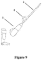
- Figure 9 is a schematic view showing a three-dimensional structure of an extended-type handheld suction cleaner according a third embodiment of the present application in an operating state.
- the main device 1 and the push rod 2 are independently taken down respectively, and are assembled together.
- the push rod 2 is a hollow rod. There is an opening on each of two ends of the push rod 2, and the opening on one end of the push rod 2 and the suction port of the main device 1 have mating structures.
- the opening on the one end is butt-joined with the suction port of the main device 1
- the rod body of the push rod 2 and the air duct of the main device form a third integral air duct
- the opening on the other end of the push rod 2 forms a suction port of the third integral air duct.
- a push rod handle 8 is provided in proximity to one end of the push rod 2, the opening on the end where the push rod handle is arranged is butt-joined with the suction port of the main device.
- the push rod 2 may be designed as a telescopic rod, may be adjusted in length as desired for long distance dust suction, thereby forming an extended-type handheld suction cleaner which can suck objects at a long distance, such as on a ceiling.
- the main device is powered by being charged or being connected to a power supply via a plug, preferably the main device is powered by a built-in battery.
- the built-in battery is located at a bottom of the main device.
- the built-in battery is attached to a side of the push rod.
Landscapes
- Engineering & Computer Science (AREA)
- Mechanical Engineering (AREA)
- Electric Suction Cleaners (AREA)
- Nozzles For Electric Vacuum Cleaners (AREA)
- Filtering Of Dispersed Particles In Gases (AREA)
Claims (10)
- Aspirateur de type séparé, deux en un, portatif à tige, comprenant :un dispositif principal (1),une tige de poussée (2), etune brosse de sol (3),dans lequel le dispositif principal (1) est un aspirateur portatif et la tige de poussée (2) est une tige creuse, chaque couple d'éléments parmi le dispositif principal, la tige de poussée et la brosse de sol sont assemblés de manière amovible,où l'aspirateur de type séparé, deux en un, portatif à tige comprend en outre un dispositif indépendant de séparation poussière-air et de stockage de poussière, qui est agencé de manière amovible entre la brosse de sol (3) et le dispositif principal (1), et dans le cas où le dispositif principal (1), la tige de poussée (2), la brosse de sol (3) et le dispositif indépendant de séparation poussière-air et de stockage de poussière sont utilisés en combinaison, le dispositif indépendant de séparation poussière-air et de stockage de poussière forme un premier dispositif de collecte de poussière (4) et un dispositif de collecte de poussière intégré du dispositif principal forme un deuxième dispositif de collecte de poussière (7),lorsque l'aspirateur de type séparé, deux en un, portatif à tige fonctionne, de l'air poussiéreux secondaire filtré est formé après le passage de l'air poussiéreux initial à travers le premier dispositif de collecte de poussière (4), et au moins une partie de la poussière dans l'air poussiéreux initial est collectée dans le premier dispositif de collecte de poussière (4) et ensuite l'air poussiéreux secondaire entre dans le deuxième dispositif de collecte de poussière (7) pour être filtré.
- Aspirateur de type séparé, deux en un, portatif à tige selon la revendication 1, dans lequel le premier dispositif de collecte de poussière (4) comprend une coupelle de collecte de poussière amovible (5) et un raccord amovible (6), et une partie arrière de la brosse de sol (3) est pourvue d'une ouverture de fixation coopérant de manière mobile avec une extrémité inférieure du raccord (6), et une extrémité supérieure du raccord (6) est pourvue d'une ouverture de fixation dans laquelle une extrémité de la tige de poussée (2) est insérée pour être fixée.
- Aspirateur de type séparé, deux en un, portatif à tige selon la revendication 2, dans lequel la coupelle de collecte de poussière (5) est fixée verticalement ou transversalement au raccord (6) de manière amovible, et la coupelle de collecte de poussière (5) a des ouvertures qui sont en communication avec un orifice d'aspiration du dispositif principal (1) et le raccord (6) respectivement.
- Aspirateur de type séparé, deux en un, portatif à tige selon la revendication 2, dans lequel la coupelle de collecte de poussière (5) est agencée de manière amovible sur la brosse de sol (3) et a des ouvertures qui sont en communication avec la brosse de sol (3) et le raccord (6) respectivement, et dans ce cas, un orifice d'aspiration du dispositif principal (1) est en communication avec le raccord (6).
- Aspirateur de type séparé, deux en un, portatif à tige selon la revendication 1, dans lequel le premier dispositif de collecte de poussière (4) ne comprend qu'une coupelle de collecte de poussière (5), la coupelle de collecte de poussière (5) est attachée de manière amovible à la tige de poussée (2), et la coupelle de collecte de poussière (5) a des ouvertures qui sont en communication avec la tige de poussée (2) et le dispositif principal (1) respectivement, ainsi un conduit d'air de la brosse de sol (3), un conduit d'air de la tige de poussée (2), un conduit d'air de la coupelle de collecte de poussière (5) et un conduit d'air du dispositif principal (1) forment un conduit d'air intégral.
- Aspirateur de type séparé, deux en un, portatif à tige selon la revendication 1, dans lequel le premier dispositif de collecte de poussière (4) ne comprend qu'une coupelle de collecte de poussière (5), la coupelle de collecte de poussière (5) est agencée de manière amovible sur la brosse de sol (3), et la coupelle de collecte de poussière (5) a des ouvertures qui sont en communication avec la brosse de sol (3) et la tige de poussée (2) respectivement, et dans ce cas, un orifice d'aspiration du dispositif principal (1) est en communication avec la tige de poussée (2), ainsi un conduit d'air de la brosse de sol (3), un conduit d'air de la coupelle de collecte de poussière (5), un conduit d'air de la tige de poussée (2) et un conduit d'air du dispositif principal (1) forment un conduit d'air intégral.
- Aspirateur de type séparé, deux en un, portatif à tige selon la revendication 1, dans lequel un moyen de loquet de verrouillage est prévu sur un corps de tige de la tige de poussée (2) et un moyen de moraillon correspondant est agencé sur un corps du dispositif principal (1), et le dispositif principal (1) et la tige de poussée (2) sont fixés par le moyen de loquet de verrouillage et le moyen de moraillon.
- Aspirateur de type séparé, deux en un, portatif à tige selon la revendication 1, dans lequel le dispositif principal (1) et la tige de poussée (2) sont combinés, formant un aspirateur portatif avec un long tuyau de raccordement.
- Aspirateur de type séparé, deux en un, portatif à tige selon la revendication 7, dans lequel il existe une ouverture sur chacune des deux extrémités de la tige de poussée (2), et l'ouverture sur une extrémité de la tige de poussée (2) et un orifice d'aspiration du dispositif principal (1) ont des structures d'accouplement, et l'ouverture sur ladite extrémité est jointe bout à bout avec l'orifice d'aspiration du dispositif principal (1), et le corps de tige de la tige de poussée (2) et le conduit d'air du dispositif principal (1) forment un troisième conduit d'air intégral, et l'ouverture sur l'autre extrémité de la tige de poussée (2) forme un orifice d'aspiration du troisième conduit d'air intégral.
- Aspirateur de type séparé, deux en un, portatif à tige selon la revendication 1, dans lequel le dispositif principal (2) est alimenté en énergie en étant chargé ou est raccordé à une alimentation électrique par l'intermédiaire d'une fiche.
Applications Claiming Priority (2)
| Application Number | Priority Date | Filing Date | Title |
|---|---|---|---|
| CN201510295844.8A CN104840150B (zh) | 2015-06-02 | 2015-06-02 | 带独立尘气分离和储灰装置的杆式手持二合一分体吸尘器 |
| PCT/CN2015/091023 WO2016192260A1 (fr) | 2015-06-02 | 2015-09-29 | Aspirateur de type séparé deux en un portatif à tige, pourvu d'un dispositif indépendant de séparation poussière-air et de stockage de poussière |
Publications (3)
| Publication Number | Publication Date |
|---|---|
| EP3305154A1 EP3305154A1 (fr) | 2018-04-11 |
| EP3305154A4 EP3305154A4 (fr) | 2019-02-20 |
| EP3305154B1 true EP3305154B1 (fr) | 2022-10-26 |
Family
ID=53840434
Family Applications (1)
| Application Number | Title | Priority Date | Filing Date |
|---|---|---|---|
| EP15893911.6A Active EP3305154B1 (fr) | 2015-06-02 | 2015-09-29 | Aspirateur de type séparé deux en un portatif à tige, pourvu d'un dispositif indépendant de séparation poussière-air et de stockage de poussière |
Country Status (4)
| Country | Link |
|---|---|
| US (1) | US10588473B2 (fr) |
| EP (1) | EP3305154B1 (fr) |
| CN (1) | CN104840150B (fr) |
| WO (1) | WO2016192260A1 (fr) |
Families Citing this family (24)
| Publication number | Priority date | Publication date | Assignee | Title |
|---|---|---|---|---|
| US10806317B2 (en) | 2018-07-19 | 2020-10-20 | Omachron Intellectual Property Inc. | Surface cleaning apparatus |
| CN104840150B (zh) * | 2015-06-02 | 2016-08-31 | 莱克电气股份有限公司 | 带独立尘气分离和储灰装置的杆式手持二合一分体吸尘器 |
| CN105249891B (zh) | 2015-11-03 | 2018-01-30 | 莱克电气股份有限公司 | 一种三级龙卷风尘杯过滤系统及包含该系统的吸尘器 |
| CN106725092A (zh) * | 2017-01-24 | 2017-05-31 | 苏州市利飞特电器有限公司 | 一种挂靠式手持吸尘器 |
| CN108497999A (zh) * | 2017-02-28 | 2018-09-07 | 科沃斯机器人股份有限公司 | 杆式清洗组件及其吸尘器 |
| US11213177B2 (en) * | 2017-09-22 | 2022-01-04 | Sharkninja Operating Llc | Hand-held surface cleaning device |
| CN108309148A (zh) * | 2018-04-14 | 2018-07-24 | 苏州爱普电器有限公司 | 表面清洁装置 |
| CN108968797B (zh) * | 2018-07-10 | 2021-10-01 | 江苏美的清洁电器股份有限公司 | 清洁设备 |
| US10791896B2 (en) | 2018-07-19 | 2020-10-06 | Omachron Intellectual Property Inc. | Surface cleaning apparatus |
| CN108888174B (zh) * | 2018-08-13 | 2024-01-12 | 天佑电器(苏州)有限公司 | 立式手持的二合一吸尘器 |
| CN108903790A (zh) * | 2018-08-13 | 2018-11-30 | 天佑电器(苏州)有限公司 | 吸尘器 |
| CN211243161U (zh) * | 2018-08-22 | 2020-08-14 | 苏州宝时得电动工具有限公司 | 吸尘器 |
| CN108836182A (zh) * | 2018-08-29 | 2018-11-20 | 苏州市春菊电器有限公司 | 一种立式推杆吸尘器的子机和立式推杆吸尘器 |
| CN109199225B (zh) * | 2018-09-30 | 2023-10-27 | 江苏美的清洁电器股份有限公司 | 吸尘器 |
| CN108903784B (zh) * | 2018-09-30 | 2024-02-02 | 江苏美的清洁电器股份有限公司 | 干湿两用吸尘器 |
| CN109394068A (zh) * | 2018-11-08 | 2019-03-01 | 天佑电器(苏州)有限公司 | 锁紧机构及具有其的吸尘器 |
| CN109464063B (zh) * | 2018-12-10 | 2023-10-20 | 江苏美的清洁电器股份有限公司 | 清洁设备 |
| CN109805836A (zh) * | 2019-02-22 | 2019-05-28 | 苏州美奥电器有限公司 | 一种双马达轻型立式吸尘器 |
| US11246462B2 (en) | 2019-11-18 | 2022-02-15 | Omachron Intellectual Property Inc. | Multi-inlet cyclone |
| US11751740B2 (en) | 2019-11-18 | 2023-09-12 | Omachron Intellectual Property Inc. | Multi-inlet cyclone |
| WO2021120859A1 (fr) * | 2019-12-19 | 2021-06-24 | Techtronic Cordless Gp | Cultivateur électrique |
| CN112641375A (zh) * | 2020-05-21 | 2021-04-13 | 安徽大汉机器人集团有限公司 | 一种吸拖一体机 |
| CN112369959A (zh) * | 2020-10-14 | 2021-02-19 | 添可智能科技有限公司 | 清洁设备 |
| AU2022281727A1 (en) * | 2021-05-27 | 2023-12-21 | Kingclean Electric Co., Ltd. | Cleaning apparatus |
Family Cites Families (25)
| Publication number | Priority date | Publication date | Assignee | Title |
|---|---|---|---|---|
| US4766638A (en) * | 1987-03-04 | 1988-08-30 | Bissell Inc. | Four-way vacuum cleaner |
| US5309600A (en) * | 1993-02-12 | 1994-05-10 | Bissell Inc. | Vacuum cleaner with a detachable vacuum module |
| CA2239503A1 (fr) * | 1995-12-04 | 1997-06-12 | Electrolux Limited | Aspirateur |
| SE510283C2 (sv) * | 1997-04-24 | 1999-05-10 | Electrolux Ab | Dammsugare |
| AU2005218490B2 (en) * | 2004-03-02 | 2010-04-01 | Bissell Inc. | Vacuum cleaner with detachable cyclonic vacuum module |
| JP2005270312A (ja) * | 2004-03-24 | 2005-10-06 | Sharp Corp | 縦型電気掃除機 |
| CN100369573C (zh) * | 2004-10-20 | 2008-02-20 | 厦门灿坤实业股份有限公司 | 一种吸尘器的集尘装置 |
| US8287655B2 (en) * | 2005-08-05 | 2012-10-16 | Stein & Co. Gmbh | Method for cleaning dirt and debris from surfaces |
| SE531125C2 (sv) * | 2007-01-19 | 2008-12-23 | Electrolux Ab | Förbättringar med avseende på luftströmningsförluster i en dammsugare |
| CN201008537Y (zh) | 2007-03-21 | 2008-01-23 | 苏州金莱克家用电器有限公司 | 吸尘器的除尘装置 |
| DE102008007985A1 (de) | 2008-02-07 | 2009-08-13 | Vorwerk & Co. Interholding Gmbh | Elektromotorisch betriebener Staubsauger |
| CN104274121B (zh) * | 2008-10-22 | 2017-05-03 | 创科地板护理技术有限公司 | 手控真空吸尘器 |
| US9427122B2 (en) * | 2009-03-13 | 2016-08-30 | Omachron Intellectual Property Inc. | Surface cleaning apparatus |
| CN201814508U (zh) * | 2010-09-13 | 2011-05-04 | 莱克电气股份有限公司 | 具有尘杯锁扣结构的便携式吸尘器 |
| CN102133070A (zh) * | 2011-03-22 | 2011-07-27 | 徐凯 | 一种结构简单、可靠耐用、性价比高的吸尘器 |
| CN202604719U (zh) * | 2011-03-22 | 2012-12-19 | 徐凯 | 一种结构简便、可靠耐用的吸尘器 |
| CN102499608B (zh) | 2011-11-18 | 2014-04-30 | 宁波锦隆电器有限公司 | 立式吸尘器 |
| DE102012211247B4 (de) * | 2012-06-29 | 2020-08-27 | BSH Hausgeräte GmbH | Kombination aus einem Kleinsauger und einem Staubsaugergehäuse sowie Kleinsauger und Staubsaugergehäuse |
| CN202739909U (zh) * | 2012-08-24 | 2013-02-20 | 宁波美妙电器有限公司 | 一种出风装置以及具有该出风装置的吸尘器 |
| CN202776154U (zh) * | 2012-08-28 | 2013-03-13 | 莱克电气股份有限公司 | 多功能吸尘器 |
| US10105022B2 (en) | 2013-09-05 | 2018-10-23 | Samsung Electronics Co., Ltd. | Vacuum cleaner |
| US9254069B2 (en) * | 2013-09-05 | 2016-02-09 | Samsung Electronics Co., Ltd. | Vacuum cleaner |
| AU2014352815B2 (en) * | 2013-11-22 | 2017-09-07 | Techtronic Industries Co. Ltd. | Vacuum cleaner including a removable dirt collection assembly |
| CN104840150B (zh) * | 2015-06-02 | 2016-08-31 | 莱克电气股份有限公司 | 带独立尘气分离和储灰装置的杆式手持二合一分体吸尘器 |
| CN204698451U (zh) * | 2015-06-02 | 2015-10-14 | 莱克电气股份有限公司 | 带独立尘气分离和储灰装置的杆式手持二合一分体吸尘器 |
-
2015
- 2015-06-02 CN CN201510295844.8A patent/CN104840150B/zh active Active
- 2015-09-29 WO PCT/CN2015/091023 patent/WO2016192260A1/fr active Application Filing
- 2015-09-29 US US15/578,426 patent/US10588473B2/en active Active
- 2015-09-29 EP EP15893911.6A patent/EP3305154B1/fr active Active
Also Published As
| Publication number | Publication date |
|---|---|
| US10588473B2 (en) | 2020-03-17 |
| CN104840150B (zh) | 2016-08-31 |
| EP3305154A4 (fr) | 2019-02-20 |
| CN104840150A (zh) | 2015-08-19 |
| WO2016192260A1 (fr) | 2016-12-08 |
| EP3305154A1 (fr) | 2018-04-11 |
| US20180177363A1 (en) | 2018-06-28 |
Similar Documents
| Publication | Publication Date | Title |
|---|---|---|
| EP3305154B1 (fr) | Aspirateur de type séparé deux en un portatif à tige, pourvu d'un dispositif indépendant de séparation poussière-air et de stockage de poussière | |
| CN106923739B (zh) | 表面清洁系统 | |
| CN106923745B (zh) | 多功能表面清洁系统 | |
| EP3446605A1 (fr) | Aspirateur à main | |
| CN104799760B (zh) | 一种基于杆体挂靠式手持吸尘器的三合一吸尘器 | |
| KR101637684B1 (ko) | 진공 청소기 | |
| CN105764396A (zh) | 具有可拆卸的集尘组件的真空吸尘器 | |
| KR20080096191A (ko) | 캐니스터/스틱 겸용 진공청소기 | |
| EP2879557B1 (fr) | Aspirateurs et filtres à poussière humides | |
| CN107773151A (zh) | 一种无线手持吸尘器 | |
| CN103417161B (zh) | 一键释放集尘桶的锁紧保护装置 | |
| CN215959668U (zh) | 一种风道水箱组合结构、便携式清洁装置和表面清洁设备 | |
| JP2014188367A (ja) | 自走式掃除機 | |
| CN108968797B (zh) | 清洁设备 | |
| CN204698451U (zh) | 带独立尘气分离和储灰装置的杆式手持二合一分体吸尘器 | |
| CN215838813U (zh) | 一种便携式清洁装置和表面清洁设备 | |
| CN204698448U (zh) | 一种基于杆体挂靠式手持吸尘器的三合一吸尘器 | |
| CN102813489A (zh) | 刚管手柄与吸尘软管的连接结构 | |
| CN216628423U (zh) | 一种主机和表面清洁设备 | |
| TW202015605A (zh) | 充電座及電動吸塵器系統 | |
| CN215838814U (zh) | 一种表面清洁设备 | |
| CN220494917U (zh) | 手持吸尘器 | |
| CN211093746U (zh) | 手持式吸尘器 | |
| CN109199233B (zh) | 用于真空吸尘器的吸管组件以及多用途真空吸尘装置 | |
| CN208524749U (zh) | 一种无线手持吸尘器 |
Legal Events
| Date | Code | Title | Description |
|---|---|---|---|
| STAA | Information on the status of an ep patent application or granted ep patent |
Free format text: STATUS: THE INTERNATIONAL PUBLICATION HAS BEEN MADE |
|
| PUAI | Public reference made under article 153(3) epc to a published international application that has entered the european phase |
Free format text: ORIGINAL CODE: 0009012 |
|
| STAA | Information on the status of an ep patent application or granted ep patent |
Free format text: STATUS: REQUEST FOR EXAMINATION WAS MADE |
|
| 17P | Request for examination filed |
Effective date: 20171214 |
|
| AK | Designated contracting states |
Kind code of ref document: A1 Designated state(s): AL AT BE BG CH CY CZ DE DK EE ES FI FR GB GR HR HU IE IS IT LI LT LU LV MC MK MT NL NO PL PT RO RS SE SI SK SM TR |
|
| AX | Request for extension of the european patent |
Extension state: BA ME |
|
| DAV | Request for validation of the european patent (deleted) | ||
| DAX | Request for extension of the european patent (deleted) | ||
| A4 | Supplementary search report drawn up and despatched |
Effective date: 20190117 |
|
| RIC1 | Information provided on ipc code assigned before grant |
Ipc: A47L 5/22 20060101ALI20190111BHEP Ipc: A47L 5/24 20060101ALI20190111BHEP Ipc: A47L 9/28 20060101ALI20190111BHEP Ipc: A47L 9/10 20060101AFI20190111BHEP |
|
| GRAP | Despatch of communication of intention to grant a patent |
Free format text: ORIGINAL CODE: EPIDOSNIGR1 |
|
| STAA | Information on the status of an ep patent application or granted ep patent |
Free format text: STATUS: GRANT OF PATENT IS INTENDED |
|
| INTG | Intention to grant announced |
Effective date: 20220518 |
|
| GRAS | Grant fee paid |
Free format text: ORIGINAL CODE: EPIDOSNIGR3 |
|
| GRAA | (expected) grant |
Free format text: ORIGINAL CODE: 0009210 |
|
| STAA | Information on the status of an ep patent application or granted ep patent |
Free format text: STATUS: THE PATENT HAS BEEN GRANTED |
|
| AK | Designated contracting states |
Kind code of ref document: B1 Designated state(s): AL AT BE BG CH CY CZ DE DK EE ES FI FR GB GR HR HU IE IS IT LI LT LU LV MC MK MT NL NO PL PT RO RS SE SI SK SM TR |
|
| REG | Reference to a national code |
Ref country code: GB Ref legal event code: FG4D |
|
| REG | Reference to a national code |
Ref country code: CH Ref legal event code: EP |
|
| REG | Reference to a national code |
Ref country code: DE Ref legal event code: R096 Ref document number: 602015081366 Country of ref document: DE |
|
| REG | Reference to a national code |
Ref country code: AT Ref legal event code: REF Ref document number: 1526438 Country of ref document: AT Kind code of ref document: T Effective date: 20221115 |
|
| REG | Reference to a national code |
Ref country code: IE Ref legal event code: FG4D |
|
| REG | Reference to a national code |
Ref country code: LT Ref legal event code: MG9D |
|
| REG | Reference to a national code |
Ref country code: NL Ref legal event code: MP Effective date: 20221026 |
|
| REG | Reference to a national code |
Ref country code: AT Ref legal event code: MK05 Ref document number: 1526438 Country of ref document: AT Kind code of ref document: T Effective date: 20221026 |
|
| PG25 | Lapsed in a contracting state [announced via postgrant information from national office to epo] |
Ref country code: NL Free format text: LAPSE BECAUSE OF FAILURE TO SUBMIT A TRANSLATION OF THE DESCRIPTION OR TO PAY THE FEE WITHIN THE PRESCRIBED TIME-LIMIT Effective date: 20221026 |
|
| PG25 | Lapsed in a contracting state [announced via postgrant information from national office to epo] |
Ref country code: SE Free format text: LAPSE BECAUSE OF FAILURE TO SUBMIT A TRANSLATION OF THE DESCRIPTION OR TO PAY THE FEE WITHIN THE PRESCRIBED TIME-LIMIT Effective date: 20221026 Ref country code: PT Free format text: LAPSE BECAUSE OF FAILURE TO SUBMIT A TRANSLATION OF THE DESCRIPTION OR TO PAY THE FEE WITHIN THE PRESCRIBED TIME-LIMIT Effective date: 20230227 Ref country code: NO Free format text: LAPSE BECAUSE OF FAILURE TO SUBMIT A TRANSLATION OF THE DESCRIPTION OR TO PAY THE FEE WITHIN THE PRESCRIBED TIME-LIMIT Effective date: 20230126 Ref country code: LT Free format text: LAPSE BECAUSE OF FAILURE TO SUBMIT A TRANSLATION OF THE DESCRIPTION OR TO PAY THE FEE WITHIN THE PRESCRIBED TIME-LIMIT Effective date: 20221026 Ref country code: FI Free format text: LAPSE BECAUSE OF FAILURE TO SUBMIT A TRANSLATION OF THE DESCRIPTION OR TO PAY THE FEE WITHIN THE PRESCRIBED TIME-LIMIT Effective date: 20221026 Ref country code: ES Free format text: LAPSE BECAUSE OF FAILURE TO SUBMIT A TRANSLATION OF THE DESCRIPTION OR TO PAY THE FEE WITHIN THE PRESCRIBED TIME-LIMIT Effective date: 20221026 Ref country code: AT Free format text: LAPSE BECAUSE OF FAILURE TO SUBMIT A TRANSLATION OF THE DESCRIPTION OR TO PAY THE FEE WITHIN THE PRESCRIBED TIME-LIMIT Effective date: 20221026 |
|
| PG25 | Lapsed in a contracting state [announced via postgrant information from national office to epo] |
Ref country code: RS Free format text: LAPSE BECAUSE OF FAILURE TO SUBMIT A TRANSLATION OF THE DESCRIPTION OR TO PAY THE FEE WITHIN THE PRESCRIBED TIME-LIMIT Effective date: 20221026 Ref country code: PL Free format text: LAPSE BECAUSE OF FAILURE TO SUBMIT A TRANSLATION OF THE DESCRIPTION OR TO PAY THE FEE WITHIN THE PRESCRIBED TIME-LIMIT Effective date: 20221026 Ref country code: LV Free format text: LAPSE BECAUSE OF FAILURE TO SUBMIT A TRANSLATION OF THE DESCRIPTION OR TO PAY THE FEE WITHIN THE PRESCRIBED TIME-LIMIT Effective date: 20221026 Ref country code: IS Free format text: LAPSE BECAUSE OF FAILURE TO SUBMIT A TRANSLATION OF THE DESCRIPTION OR TO PAY THE FEE WITHIN THE PRESCRIBED TIME-LIMIT Effective date: 20230226 Ref country code: HR Free format text: LAPSE BECAUSE OF FAILURE TO SUBMIT A TRANSLATION OF THE DESCRIPTION OR TO PAY THE FEE WITHIN THE PRESCRIBED TIME-LIMIT Effective date: 20221026 Ref country code: GR Free format text: LAPSE BECAUSE OF FAILURE TO SUBMIT A TRANSLATION OF THE DESCRIPTION OR TO PAY THE FEE WITHIN THE PRESCRIBED TIME-LIMIT Effective date: 20230127 |
|
| REG | Reference to a national code |
Ref country code: DE Ref legal event code: R097 Ref document number: 602015081366 Country of ref document: DE |
|
| PG25 | Lapsed in a contracting state [announced via postgrant information from national office to epo] |
Ref country code: SM Free format text: LAPSE BECAUSE OF FAILURE TO SUBMIT A TRANSLATION OF THE DESCRIPTION OR TO PAY THE FEE WITHIN THE PRESCRIBED TIME-LIMIT Effective date: 20221026 Ref country code: RO Free format text: LAPSE BECAUSE OF FAILURE TO SUBMIT A TRANSLATION OF THE DESCRIPTION OR TO PAY THE FEE WITHIN THE PRESCRIBED TIME-LIMIT Effective date: 20221026 Ref country code: EE Free format text: LAPSE BECAUSE OF FAILURE TO SUBMIT A TRANSLATION OF THE DESCRIPTION OR TO PAY THE FEE WITHIN THE PRESCRIBED TIME-LIMIT Effective date: 20221026 Ref country code: DK Free format text: LAPSE BECAUSE OF FAILURE TO SUBMIT A TRANSLATION OF THE DESCRIPTION OR TO PAY THE FEE WITHIN THE PRESCRIBED TIME-LIMIT Effective date: 20221026 Ref country code: CZ Free format text: LAPSE BECAUSE OF FAILURE TO SUBMIT A TRANSLATION OF THE DESCRIPTION OR TO PAY THE FEE WITHIN THE PRESCRIBED TIME-LIMIT Effective date: 20221026 |
|
| PG25 | Lapsed in a contracting state [announced via postgrant information from national office to epo] |
Ref country code: SK Free format text: LAPSE BECAUSE OF FAILURE TO SUBMIT A TRANSLATION OF THE DESCRIPTION OR TO PAY THE FEE WITHIN THE PRESCRIBED TIME-LIMIT Effective date: 20221026 Ref country code: AL Free format text: LAPSE BECAUSE OF FAILURE TO SUBMIT A TRANSLATION OF THE DESCRIPTION OR TO PAY THE FEE WITHIN THE PRESCRIBED TIME-LIMIT Effective date: 20221026 |
|
| PLBE | No opposition filed within time limit |
Free format text: ORIGINAL CODE: 0009261 |
|
| STAA | Information on the status of an ep patent application or granted ep patent |
Free format text: STATUS: NO OPPOSITION FILED WITHIN TIME LIMIT |
|
| 26N | No opposition filed |
Effective date: 20230727 |
|
| PG25 | Lapsed in a contracting state [announced via postgrant information from national office to epo] |
Ref country code: SI Free format text: LAPSE BECAUSE OF FAILURE TO SUBMIT A TRANSLATION OF THE DESCRIPTION OR TO PAY THE FEE WITHIN THE PRESCRIBED TIME-LIMIT Effective date: 20221026 |
|
| PGFP | Annual fee paid to national office [announced via postgrant information from national office to epo] |
Ref country code: FR Payment date: 20230927 Year of fee payment: 9 Ref country code: DE Payment date: 20230911 Year of fee payment: 9 |
|
| REG | Reference to a national code |
Ref country code: CH Ref legal event code: PL |