EP3304577B1 - Massenfilter mit verlängerter lebensdauer - Google Patents
Massenfilter mit verlängerter lebensdauer Download PDFInfo
- Publication number
- EP3304577B1 EP3304577B1 EP16727783.9A EP16727783A EP3304577B1 EP 3304577 B1 EP3304577 B1 EP 3304577B1 EP 16727783 A EP16727783 A EP 16727783A EP 3304577 B1 EP3304577 B1 EP 3304577B1
- Authority
- EP
- European Patent Office
- Prior art keywords
- mass
- mass filter
- ions
- filter
- electrodes
- Prior art date
- Legal status (The legal status is an assumption and is not a legal conclusion. Google has not performed a legal analysis and makes no representation as to the accuracy of the status listed.)
- Active
Links
Images


Classifications
-
- H—ELECTRICITY
- H01—ELECTRIC ELEMENTS
- H01J—ELECTRIC DISCHARGE TUBES OR DISCHARGE LAMPS
- H01J49/00—Particle spectrometers or separator tubes
- H01J49/26—Mass spectrometers or separator tubes
- H01J49/34—Dynamic spectrometers
- H01J49/42—Stability-of-path spectrometers, e.g. monopole, quadrupole, multipole, farvitrons
- H01J49/4205—Device types
- H01J49/421—Mass filters, i.e. deviating unwanted ions without trapping
-
- H—ELECTRICITY
- H01—ELECTRIC ELEMENTS
- H01J—ELECTRIC DISCHARGE TUBES OR DISCHARGE LAMPS
- H01J49/00—Particle spectrometers or separator tubes
- H01J49/0027—Methods for using particle spectrometers
-
- H—ELECTRICITY
- H01—ELECTRIC ELEMENTS
- H01J—ELECTRIC DISCHARGE TUBES OR DISCHARGE LAMPS
- H01J49/00—Particle spectrometers or separator tubes
- H01J49/0027—Methods for using particle spectrometers
- H01J49/0031—Step by step routines describing the use of the apparatus
-
- H—ELECTRICITY
- H01—ELECTRIC ELEMENTS
- H01J—ELECTRIC DISCHARGE TUBES OR DISCHARGE LAMPS
- H01J49/00—Particle spectrometers or separator tubes
- H01J49/02—Details
- H01J49/06—Electron- or ion-optical arrangements
- H01J49/062—Ion guides
- H01J49/063—Multipole ion guides, e.g. quadrupoles, hexapoles
-
- H—ELECTRICITY
- H01—ELECTRIC ELEMENTS
- H01J—ELECTRIC DISCHARGE TUBES OR DISCHARGE LAMPS
- H01J49/00—Particle spectrometers or separator tubes
- H01J49/02—Details
- H01J49/06—Electron- or ion-optical arrangements
- H01J49/067—Ion lenses, apertures, skimmers
-
- H—ELECTRICITY
- H01—ELECTRIC ELEMENTS
- H01J—ELECTRIC DISCHARGE TUBES OR DISCHARGE LAMPS
- H01J49/00—Particle spectrometers or separator tubes
- H01J49/26—Mass spectrometers or separator tubes
- H01J49/34—Dynamic spectrometers
- H01J49/42—Stability-of-path spectrometers, e.g. monopole, quadrupole, multipole, farvitrons
- H01J49/4205—Device types
- H01J49/421—Mass filters, i.e. deviating unwanted ions without trapping
- H01J49/4215—Quadrupole mass filters
-
- H—ELECTRICITY
- H01—ELECTRIC ELEMENTS
- H01J—ELECTRIC DISCHARGE TUBES OR DISCHARGE LAMPS
- H01J49/00—Particle spectrometers or separator tubes
- H01J49/26—Mass spectrometers or separator tubes
- H01J49/34—Dynamic spectrometers
- H01J49/42—Stability-of-path spectrometers, e.g. monopole, quadrupole, multipole, farvitrons
- H01J49/4205—Device types
- H01J49/4255—Device types with particular constructional features
Definitions
- the present invention relates generally to mass and/or ion mobility spectrometers and in particular to mass filters that selectively transmit ions within a specific range of mass to charge ratios.
- Ions having values of a and q that result in unstable ion trajectories generally impact on the rods of the quadrupole and are lost.
- This property is exploited when the quadrupole rod set is used as a mass filter, such that the majority of the ions that are not desired to be transmitted by the mass filter impact on the inner surfaces of the rod electrodes.
- the inner surfaces of the rods become contaminated by the ions and the electronic charge builds up on their surfaces.
- local charging of the contaminated surfaces results in degradation of performance of the mass filter. This may result in loss of transmission, loss of resolution or poor peak shape. If this occurs the mass filter must be removed from the vacuum chamber and cleaned.
- EP 3032569 discloses electrodes specifically shaped to prevent surface contamination from unstable ions.
- WO 2014/197348 discloses two multipole sections in the same vacuum chamber, wherein the first multipole section is provided with apertures.
- US 2011/186733 discloses an ion trap with electrodes having an aperture through which ions can be ejected.
- US 2010/038530 discloses using an axially segmented multipole rod set.
- WO 2015/092399 discloses using a mass filter with axially segmented electrodes connected to a quadrupole mass analyser.
- US 2005/127283 and US 3473020 each disclose the preamble of the independent claims.
- the present invention provides a lower resolution first mass filter upstream of a higher resolution second mass filter.
- the first mass filter may filter out the majority of unwanted background ions and hence prevent these ions from impacting on the electrodes of the second mass filter and causing surface charging. This maintains the performance of the second mass filter over an extended period of time.
- the effect of surface charging on the first mass filter is less severe than that for second mass filters and hence the use of the first mass filter improves the transmission characteristics of the overall instrument as compared to the use of the higher resolution mass filter alone.
- the aperture and/or recess in the at least one electrode of the first mass filter is configured such that some or all of the ions which have unstable trajectories in the first mass filter pass through the electrode or impinge on a surface of the electrode that is remote from the surface of the electrode closest to the central axis of the first mass filter. As such, surface charging on the first mass filter is maintained relatively low, thereby maintaining good transmission characteristics of the first mass filter.
- GB 2388705 discloses the use of a low resolution sacrificial filter upstream of a high resolution analytical filter to avoid contamination of the analytical filter.
- the sacrificial filter does not comprise an electrode having an aperture extending entirely therethrough or a recess extending only partially therethrough, wherein the aperture or recess is arranged and configured such that ions that are unstable in the sacrificial filter pass through or into the aperture or recess.
- the ions strike the surfaces of the electrodes in the sacrificial filter close to the ion transmission axis and these surfaces become contaminated relatively quickly, causing surface charging of the electrodes. As such, the performance of the sacrificial filter is reduced relatively quickly.
- the second range of mass to charge ratios according to the first aspect of the present invention is narrower than the first range of mass to charge ratios, and is within the first range of mass to charge ratios.
- the second range of mass to charge ratios may be capable of transmitting ions of only a single mass to charge ratio.
- the first range of mass to charge ratios may be the range of mass to charge ratios able to be simultaneously transmitted by the first mass filter at any given time
- the second range of mass to charge ratios may be the range of mass to charge ratios able to be simultaneously transmitted by the second mass filter at substantially said given time.
- the first mass filter and/or second mass filter may be a multipole mass filter, such as a quadrupole mass filter.
- the method may comprise applying RF and DC voltages to electrodes of the first mass filter and/or to electrodes of the second mass filter so as to confine ions desired to be transmitted between the electrodes and to cause ions that are not desired to be transmitted to be unstable and not confined between the electrodes.
- the RF and DC voltages may be applied such that at least some of the ions that are unstable in the first mass filter pass into or through said aperture and/or recess in the electrode.
- the method may comprise applying RF voltages having the same amplitude and/or frequency to the electrodes of the first and second mass filters, and applying a lower amplitude DC resolving voltage to the first mass filter than the second mass filter.
- At least some of the ions filtered out by the first and/or second mass filters may impact on electrodes of the first and/or second mass filters respectively. Fewer ions may impact on the electrodes of the second mass filter than the first mass filter.
- the first range of mass to charge ratios may be centred on substantially the same mass to charge ratio as the second range of mass to charge ratios.
- the second mass range may have a width that is x% of the first mass range, wherein x is selected from the group consisting of: ⁇ 95; ⁇ 90; ⁇ 85; ⁇ 80; ⁇ 75; ⁇ 70; ⁇ 65; ⁇ 60; ⁇ 55; ⁇ 50; ⁇ 45; ⁇ 40; ⁇ 35; ⁇ 30; ⁇ 25; ⁇ 20; ⁇ 15; ⁇ 10; and ⁇ 5.
- the method comprises guiding the ions transmitted by the first mass filter into the second mass filter using a RF-only first ion guide arranged between, optionally directly between, the first mass filter and the second mass filter.
- the method may comprise guiding the ions into the first mass filter using a second ion guide arranged upstream, optionally directly upstream, of the first mass filter.
- the second ion guide is an RF-only ion guide to which only RF potentials are applied and not DC potentials.
- the amplitude of the RF voltage applied to the first ion guide may be smaller or the same as the amplitude of the RF voltage applied to the electrodes of the first and/or second mass filter.
- the amplitude of the RF voltage applied to the second ion guide may be smaller or the same as the amplitude of the RF voltage applied to the electrodes of the first and/or second mass filter.
- the amplitude of the RF voltage applied to the first ion guide may be the same as the amplitude of the RF voltage applied to the second ion guide.
- the first ion guide is arranged and provided so as to control the fringing electric fields at the entrance to the second mass filter so as to allow ions to enter the second mass filter without becoming unstable.
- the second ion guide may be arranged and provided so as to control the fringing electric fields at the entrance to the first mass filter so as to allow ions to enter the first mass filter without becoming unstable.
- the first and/or second ion guide may be a multipole ion guide such as a quadrupole ion guide.
- ion guides may be used, such as an ion tunnel ion guide formed from a plurality of apertured electrodes spaced apart along the axis of the ion guide and operated such that ions are guided through the apertures.
- the method may comprise operating the first ion guide as a mass filter so as to only transmit ions having mass to charge ratios at or above a first threshold value, wherein the first threshold value is at or below the lower limit of said second range of mass to charge ratios; and/or operating the first ion guide as a mass filter so as to only transmit ions having mass to charge ratios at or below a second threshold value, wherein the second threshold value is at or above said second range of mass to charge ratios.
- the first threshold value may be between the lower limits of the first and second ranges of mass to charge ratios.
- the second threshold value may be between the upper limits of the first and second ranges of mass to charge ratios.
- the method may comprise operating the second ion guide as a mass filter so as to only transmit ions having mass to charge ratios at or above a third threshold value, wherein the third threshold value is at or below the lower limit of said first range of mass to charge ratios; and/or operating the first ion guide as a mass filter so as to only transmit ions having mass to charge ratios at or below a fourth threshold value, wherein the fourth threshold value is at or above said first range of mass to charge ratios
- At least one of the electrodes of the second ion guide may comprise an aperture extending entirely through the electrode and/or comprises a recess extending only partially through the electrode, wherein the aperture and/or recess may be arranged and configured such that ions that are unstable in the second ion guide pass into or through the aperture and/or into the recess such that they are not transmitted by the second ion guide.
- Some benefit may be obtained by providing an aperture or recess in at least one of the electrodes of the second ion guide, e.g. to reduce contamination from ions that are unstable in the ion guide.
- the aperture and/or recess is configured such that some or all of the ions which have unstable trajectories in the first mass filter or second ion guide either pass through the electrode or impinge on a surface of the electrode that is remote from the surface of the electrode closest to the central axis of the first mass filter or second ion guide. This eliminates or reduces surface charging of the electrode near to the ion transmission axis through the first mass filter or second ion guide, thus maintaining good ion transmission properties.
- the electrode having the aperture or recess may be elongated in a direction along the length of the first mass filter or second ion guide, and the aperture may be a slotted aperture or the recess is a slotted recess.
- the aperture and/or recess may extend over only part of the length of the electrode. It is also contemplated that a plurality of such apertures and/or recesses may be arranged along the length of the electrode. Alternatively, the aperture and/or recess may extend over the entire length of the electrode. For example, it is contemplated that the aperture may divide the electrode into two separate portions.
- the aperture or recess may increase in cross-sectional area in a direction away from the central axis of the first mass filter or second ion guide, e.g. so that the cross-sectional area increases in a tapered manner in a radially outward direction.
- any one of the first mass filter, second mass filter, first ion guide or second ion guide may be a multipole rod set of electrodes such as a quadrupole rod set. Any number of electrodes in the rod set, including all rod electrodes, may comprise the aperture and/or recess described herein.
- the method may comprise arranging a conductive grid or mesh over or in the aperture or recess so as to support an electric field generated by the electrode.
- Ions that pass into or through the aperture or recess may not be detected and may be neutralised or discarded.
- At least one of the electrodes of the first mass filter and/or at least one of the electrodes of the second mass filter and/or at least one of the electrodes of the first ion guide and/or at least one of the electrodes of the second ion guide; may be axially segmented so as to comprise segments that are spaced apart along the longitudinal axis by one or more gaps, optionally wherein the gaps are arranged and configured such that ions that are unstable in the mass filter or ion guide pass into or through the gaps such that they are not transmitted by the mass filter or ion guide.
- All of the electrodes of the first mass filter and/or second mass filter and/or first ion guide and/or second ion guide may be segmented.
- At least some of the electrode segments may comprise said apertures or recesses.
- At least some of the electrodes of the first mass filter and/or second ion guide may be heated. Heating the first mass filter and/or second ion guide prevents or inhibits contaminants from condensing onto the electrodes of the first mass filter and/or second ion guide, and hence reduces surface charging of these components. Heating the electrodes may cause thermal expansion of the electrodes.
- the effects of heating the electrodes are less problematic than if the electrodes of the second mass filter were heated. For example, if the second mass filter was heated then the instrument may be required to be left to stabilise for several hours before use.
- the second mass filter may be unheated. This avoids thermal expansion of the electrodes in the second mass filter and the related adverse effects on its resolution.
- the first ion guide may be unheated. This provides a thermal break between heated first mass filter and the unheated second mass filter, thus minimising heat transfer to the second mass filter, which would otherwise adversely affect its performance. However, it is contemplated that the first ion guide may be heated.
- An RF-only post filter may be provided downstream of the second mass filter, which may be unheated.
- At least some of the electrodes of the second ion guide may be heated.
- At least some of the electrodes of the second mass filter may be heated.
- the electrodes may be heated to a temperature selected from the group consisting of: ⁇ 40 °C; ⁇ 50 °C; ⁇ 60 °C; ⁇ 80 °C; ⁇ 100 °C; ⁇ 120 °C; ⁇ 140 °C; ⁇ 160 °C; ⁇ 180 °C; ⁇ 200 °C; and between 100 °C and 300 °C.
- the pressure in the first mass filter, first ion guide and second mass filter (and optionally second ion guide) may be in the range of 10 -7 mbar to 10 -4 mbar.
- the pressure within the first mass filter, first ion guide and second mass filter may be either ⁇ 9 ⁇ 10 -3 mbar or between 10 -7 and 9 ⁇ 10 -3 mbar.
- the pressure within the first mass filter, first ion guide and second mass filter may be selected from the group consisting of: (i) ⁇ 0.0001 mbar; (ii) 0.0001-0.001 mbar; (iii) 0.001-0.01 mbar; (iv) 0.01 -0.1 mbar; (v) 0.1-1 mbar; (vi) 1-10 mbar; and (vii) 10-100 mbar.
- the first mass filter, second mass filter and first ion guide (and optionally second ion guide) are arranged in a single vacuum chamber.
- the method may comprise applying an AC or RF voltage to the electrodes of the first mass filter and/or second mass filter (optionally and/or first ion guide and/or second ion guide); wherein the frequency of the AC or RF voltage is ⁇ 1MHz or > 1 MHz.
- the frequency may be selected from the group consisting of: (i) ⁇ 100 kHz; (ii) 100-200 kHz; (iii) 200-300 kHz; (iv) 300-400 kHz; (v) 400-500 kHz; (vi) 0.5-1.0 MHz; (vii) 1.0-1.5 MHz; (viii) 1.5-2.0 MHz; (ix) 2.0-2.5 MHz; (x) 2.5-3.0 MHz; (xi) 3.0-3.5 MHz; (xii) 3.5-4.0 MHz; (xiii) 4.0-4.5 MHz; (xiv) 4.5-5.0 MHz; (xv) 5.0-5.5 MHz; (xvi) 5.5-6.0 MHz; (xvii) 6.0-6.5 MHz; (xviii) 6.5-7.0 MHz; (xix) 7.0-7.5 MHz; (xx) 7.5-8.0 MHz; (xxi) 8.0-8.5 MHz; (xxii) 8.5-9.0 MHz;
- the first mass filter may be shorter in length than the second mass filter.
- the method may comprise detecting ions transmitted by the second mass filter, and/or or mass analysing ions transmitted by the second mass filter, and/or ion mobility analysing ions transmitted by the second mass filter.
- the present invention also provides a method of mass spectrometry and/or ion mobility spectrometry comprising a method as described herein.
- the method may further comprise detecting ions transmitted by the mass filter(s), and/or or mass analysing ions transmitted by mass filter(s), and/or ion mobility analysing ions transmitted by the mass filter(s).
- the spectrometer may be arranged and configured such that it may perform any of the methods described herein.
- the controller may be set up and configured to perform the methods described herein.
- the spectrometer described herein may comprise:
- the spectrometer may comprise an electrostatic ion trap or mass analyser that employs inductive detection and time domain signal processing that converts time domain signals to mass to charge ratio domain signals or spectra.
- Said signal processing may include, but is not limited to, Fourier Transform, probabilistic analysis, filter diagonalisation, forward fitting or least squares fitting.
- the spectrometer may comprise either:
- the spectrometer may comprise a device arranged and adapted to supply an AC or RF voltage to the electrodes.
- the AC or RF voltage preferably has an amplitude selected from the group consisting of: (i) ⁇ 50 V peak to peak; (ii) 50-100 V peak to peak; (iii) 100-150 V peak to peak; (iv) 150-200 V peak to peak; (v) 200-250 V peak to peak; (vi) 250-300 V peak to peak; (vii) 300-350 V peak to peak; (viii) 350-400 V peak to peak; (ix) 400-450 V peak to peak; (x) 450-500 V peak to peak; and (xi) > 500 V peak to peak.
- the AC or RF voltage preferably has a frequency selected from the group consisting of: (i) ⁇ 100 kHz; (ii) 100-200 kHz; (iii) 200-300 kHz; (iv) 300-400 kHz; (v) 400-500 kHz; (vi) 0.5-1.0 MHz; (vii) 1.0-1.5 MHz; (viii) 1.5-2.0 MHz; (ix) 2.0-2.5 MHz; (x) 2.5-3.0 MHz; (xi) 3.0-3.5 MHz; (xii) 3.5-4.0 MHz; (xiii) 4.0-4.5 MHz; (xiv) 4.5-5.0 MHz; (xv) 5.0-5.5 MHz; (xvi) 5.5-6.0 MHz; (xvii) 6.0-6.5 MHz; (xviii) 6.5-7.0 MHz; (xix) 7.0-7.5 MHz; (xx) 7.5-8.0 MHz; (xxi) 8.0-8.5 MHz; (xxii) 8.5
- the spectrometer may comprise a chromatography or other separation device upstream of an ion source.
- the chromatography separation device may comprise a liquid chromatography or gas chromatography device.
- the separation device may comprise: (i) a Capillary Electrophoresis (“CE”) separation device; (ii) a Capillary Electrochromatography (“CEC”) separation device; (iii) a substantially rigid ceramic-based multilayer microfluidic substrate (“ceramic tile”) separation device; or (iv) a supercritical fluid chromatography separation device.
- the ion guide may be maintained at a pressure selected from the group consisting of: (i) ⁇ 0.0001 mbar; (ii) 0.0001-0.001 mbar; (iii) 0.001-0.01 mbar; (iv) 0.01-0.1 mbar; (v) 0.1-1 mbar; (vi) 1-10 mbar; and (vii) 10-100 mbar.
- Analyte ions may be subjected to Electron Transfer Dissociation ("ETD") fragmentation in an Electron Transfer Dissociation fragmentation device.
- ETD Electron Transfer Dissociation
- Analyte ions may be caused to interact with ETD reagent ions within an ion guide or fragmentation device.
- analyte ions are fragmented or are induced to dissociate and form product or fragment ions upon interacting with reagent ions; and/or (b) electrons are transferred from one or more reagent anions or negatively charged ions to one or more multiply charged analyte cations or positively charged ions whereupon at least some of the multiply charged analyte cations or positively charged ions are induced to dissociate and form product or fragment ions; and/or (c) analyte ions are fragmented or are induced to dissociate and form product or fragment ions upon interacting with neutral reagent gas molecules or atoms or a non-ionic reagent gas; and/or (d) electrons are transferred from one or more neutral, non-ionic or uncharged basic gases or vapours to one or more multiply charged analyte cations or positively charged ions whereupon at least some of the multiply charged analy
- the multiply charged analyte cations or positively charged ions preferably comprise peptides, polypeptides, proteins or biomolecules.
- the reagent anions or negatively charged ions are derived from a polyaromatic hydrocarbon or a substituted polyaromatic hydrocarbon; and/or (b) the reagent anions or negatively charged ions are derived from the group consisting of: (i) anthracene; (ii) 9,10 diphenyl-anthracene; (iii) naphthalene; (iv) fluorine; (v) phenanthrene; (vi) pyrene; (vii) fluoranthene; (viii) chrysene; (ix) triphenylene; (x) perylene; (xi) acridine; (xii) 2,2' dipyridyl; (xiii) 2,2' biquinoline; (xiv) 9-anthracenecarbonitrile; (xv) dibenzothiophene; (xvi) 1,10'-phenanthroline;
- the process of Electron Transfer Dissociation fragmentation may comprise interacting analyte ions with reagent ions, wherein the reagent ions comprise dicyanobenzene, 4-nitrotoluene or azulene reagent ions.
- a low performance resolving quadrupole is placed prior to a main analytical quadrupole.
- the main analytical quadrupole is set to transmit a sub-set of those mass to charge ratio values transmitted by the low performance quadrupole.
- Both quadrupoles are set with transmission windows substantially centred on the mass to charge ratio of interest.
- the range of mass to charge ratio values transmitted by the main analytical quadrupole is significantly less than that transmitted by the low performance quadrupole. Ions with unstable trajectories in the first, low performance quadrupole will be lost to the rods of the low performance quadrupole. This prevents the majority of unwanted background ions from contaminating the rods of the main analytical quadrupole and hence the performance of the analytical quadrupole is maintained over an extended period of time.
- the main effect of local charging of the quadrupole rod electrodes is that the transmission at higher resolving powers is affected.
- an analytical quadrupole may be operated with a mass to charge ratio transmission range of 0.2 to 2 amu, centred on an ion of interest.
- the analytical quadrupole is operated at a significantly lower resolution, for example a mass to charge ratio transmission range of 10 to 50 amu centred on the mass to charge ratio of interest, then the effect of surface charging on the transmission of the mass to charge ratio of interest is far less severe.
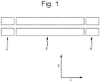
- Fig. 1 shows a cross-sectional view (in the y-z plane) of a schematic of a prior art instrument comprising a short RF-only pre-filter or Brubaker lens 2 positioned directly upstream of a main analytical quadrupole 4.
- This RF-only pre-filter 2 is supplied with an RF voltage having approximately 50-90% of the amplitude of the RF voltage that is applied to the main analytical quadrupole mass filter 4.
- the purpose of the pre-filter is to control fringing fields at the entrance to the main resolving quadrupole so as to allow ions to enter the RF-confined environment without becoming unstable and without initially experiencing the effects of the resolving DC applied to the main analytical quadrupole mass filter 4.
- An RF voltage and a DC resolving voltage is applied to the main analytical quadrupole mass filter 4 in order to mass filter the ions.
- An RF-only post-filter 6 is also provided at the exit of the analytical quadrupole mass filter 4 for conditioning ions for acceptance into a downstream device (not shown).
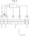
- Fig. 2 shows a cross-sectional view (in the y-z plane) of a schematic of an instrument not in accordance with the present invention and similar to that shown in Fig. 1 , except that it further comprises a relatively short, low performance analytical quadrupole mass filter 8 positioned directly upstream the main analytical quadrupole mass filter 4.
- a short RF-only pre-filter or Brubaker lens 2 may be positioned directly upstream of the short analytical quadrupole mass filter 8.
- One or more RF-only post filter 6 may be positioned downstream of the main analytical quadrupole mass filter 4.
- an RF voltage supply 12 applies an RF voltage to the electrodes of the pre-filter or Brubaker lens 2.
- the pre-filter or Brubaker lens 2 may comprise a quadrupole rod set.
- a DC voltage may not be applied to the pre-filter or lens 2.
- An RF voltage supply 14 and a DC voltage supply 16 apply RF and DC voltages, respectively, to the electrodes of the low performance analytical quadrupole mass filter 8 such that the low performance analytical quadrupole mass filter 8 is only capable of transmitting ions having a first range of mass to charge ratios.
- An RF voltage supply 18 and a DC voltage supply 20 apply RF and DC voltages, respectively, to the electrodes of the main analytical quadrupole mass filter 4 such that the main analytical quadrupole mass filter 4 is only capable of transmitting ions having a second range of mass to charge ratios, which is narrower than the first range of mass to charge ratios transmitted by the low performance analytical quadrupole mass filter 8.
- An RF voltage supply 22 applies an RF voltage to the electrodes of the post -filter 6, which may comprise a quadrupole rod set. A DC voltage may not be applied to the post-filter 6.
- a controller 24 is provided so as to control the above described voltage supplies.
- ions are transmitted into the pre-filter or lens 2 and guided through the pre-filter or lens 2 and into the low performance analytical quadrupole mass filter 8.
- the RF voltage applied to the pre-filter or lens 2 may be of lower amplitude than the RF voltage applied to the low performance analytical quadrupole mass filter 8 and/or to the main analytical quadrupole mass filter 4 so as to reduce transmission losses on entry to the low performance analytical quadrupole mass filter 8 due to fringe fields.
- the RF-only pre-filter or lens 2 may also act as a low mass cut-off filter since the RF voltage supply 13 may be controlled so as to apply RF voltages that radially confine only ions above a particular cut-off mass to charge ratio.
- the ions are then transmitted into the low performance analytical quadrupole mass filter 8.
- the RF and DC voltages applied to mass filter 8 cause only ions in the first range of mass to charge ratios to be radially confined and hence transmitted to the exit of the mass filter 8. Ions having mass to charge ratios outside of this range are filtered out by the mass filter 8, e.g. by being radially excited into the electrodes of the mass filter 8. These ions are not transmitted to the exit of the mass filter 8.
- Ions in the first range of mass to charge ratios are then transmitted into the main analytical mass filter 4.
- the RF and DC voltages applied to main analytical mass filter 4 cause only ions in the second, narrower range of mass to charge ratios to be radially confined and hence transmitted to the exit of the main analytical mass filter 4.
- Ions having mass to charge ratios outside of this second range are filtered out by the main analytical mass filter 4, e.g. by being radially excited into the electrodes of the mass filter 4. These ions are not transmitted to the exit of the main analytical mass filter 4.
- the provision of the low performance analytical quadrupole mass filter 8 enables many ions outside of the second range of mass to charge ratios to be filtered out upstream of the main analytical filter 4.
- these ions are not required to be filtered out by the main analytical filter 4 and hence do not impact on the electrodes of the main analytical filter 4. This helps avoid contamination of the main analytical filter 4 and reduces surface charging of the main analytical filter 4, which would degrade its ion transmission properties.
- the low performance analytical quadrupole mass filter 8 may be provided with the same amplitude and frequency RF voltage as the main analytical filter 4. It will therefore be appreciated that they may have the same RF voltage supply. However, the low performance analytical quadrupole mass filter 8 may be provided with a lower amplitude DC voltage than the main analytical filter 4 such that the resolution for the low performance analytical quadrupole mass filter 8 is lower than that of the main analytical mass filter 4, but the set mass transmission window of both mass filters 8,4 may be centered on substantially the same mass to charge ratio value.
- Ions in the second range of mass to charge ratios that are transmitted by the main mass filter 4 are transmitted downstream, e.g. into the post-filter 6.
- the RF voltage applied to the post-filter radially confines these ions so that they are guided downstream.
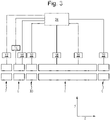
- Fig. 3 shows a schematic of an embodiment for overcoming this.
- Fig. 3 shows a schematic of an instrument according to an embodiment of the present invention.
- This instrument corresponds to that shown in Fig. 2 , except that a further RF-only pre-filter 30 is positioned directly between the low performance quadrupole mass filter 8 and the main analytical mass filter 4.
- the pre-filter 30 may comprise a quadrupole rod set.
- An RF voltage supply 32 is controlled by the controller 24 so as to apply an RF voltage to the electrodes of the pre-filter 30 for radially confining ions within the pre-filter 30 and guiding them between the low resolution mass filter 8 and main analytical mass filter 4.
- the RF-only pre-filter 30 effectively shields the main analytical mass filter 4 from the low resolution mass filter 8. In this instrument the performance of the main analytical mass filter 8 is therefore not compromised.
- the amplitude of the RF voltage applied to pre-filters 2 and 30 may be the same. As such voltage supplies 12 and 32 may be the same supply.
- the RF voltage applied to pre-filters 2 and 30 may be, for example, approximately 67% of the amplitude of the RF voltage that is applied to the low performance mass filter 8 and/or main analytical quadrupole 4.
- the RF only pre-filter 2 acts as a low-mass cut-off such that ions having mass to charge ratio values such that q > 0.908 become unstable and will be lost to the electrodes of the pre-filter 2.
- the low resolution mas filter 8 may typically be operated with a mass to charge ratio transmission window of 20 Da. Under these conditions only mass to charge ratio values of M +/-10 Da will be transmitted to the main analytical mass filter 4, assuming the mass transmission window is centered on the mass to charge ratio of interest M.
- the main analytical mass filter 4 is typically operated with a mass to charge ratio transmission window of 0.5 to 1 Da, which may also be centered on the mass to charge ratio of interest M.
- the presence of the low resolution mass filter 4 ensures that the majority of unwanted ions do not impact upon the electrodes of the main analytical mass filter 4, thus minimising contamination and subsequent charging of the electrodes of the main analytical mass filter 4.
- Fig. 4 shows a cross-sectional view (in the x-y plane) of an embodiment of the low performance mass filter 8 described above.
- the mass filter 8 comprises four elongated rod electrodes 42-48 having longitudinal axes that extend in the z-direction.
- the RF voltage supply 14 is provided for delivering RF confinement voltages of opposite phases to different rod electrodes, as is known in the art.
- the DC power supply 16 is provided for delivering DC resolving voltages of opposite polarities to different rod electrodes, as is known in the art.
- Each of the rod electrodes 42-48 comprises a tapered slotted aperture 43 that extends all of the way through the electrode, from an ion entrance opening facing the ion optical axis through the mass filter to an ion exit opening facing radially outward from the mass filter.
- the slot 43 tapers outwardly in a direction from the ion entrance opening to the ion exit opening, i.e. the slot 43 has a cross sectional area in the x-z plane that increases in a direction from the ion entrance opening to the ion exit opening.
- a grid or mesh electrode 45 may be provided over the ion entrance opening of each slot 43 for substantially maintaining the electric field profile of a conventional quadrupole rod electrode, i.e. a rod electrode not having a slot 43.
- Fig. 4 shows the trajectories 47 of positive ions that have mass to charge ratios that are higher than the mass to charge ratio which the mass filter 8 is set to transmit, i.e. for ions outside of the first range of mass to charge ratios. These ions exit the mass filter 8 in the y-direction through the slots 43.
- Fig. 4 also shows the trajectories 49 of negative ions that have mass to charge ratios that are lower than the mass to charge ratio which the mass filter 8 is set to transmit, i.e. for ions outside of the first range of mass to charge ratios. These ions exit the mass filter 8 in the x-direction through the slots 43.
- the mass filter 8 is able to filter out ions without these filtered ions impacting on the electrodes 42-48 and hence without the filtered ions causing surface contamination and charging of the electrodes 42-48. Some of the filtered ions may impact on the electrodes 42-48, on the side walls of the slotted apertures 43 between the ion entrance openings and ion exit openings. However, even if this causes surface contamination and charging, this occurs away from the ion optical axis through the mass filter 8 and hence is less problematic.
- Fig. 5 shows a cross-sectional view (in the x-y plane) of another embodiment of the low performance mass filter 8.
- This embodiment is the same as that shown and described in relation to Fig. 4 , except that each of the rod electrodes 42-48 comprises a grooved recess 50 in the inner surface of the electrode, rather than an aperture 43 extending entirely through the electrode.
- Each recess 50 extends part way through its respective electrode 42-47, from an ion entrance opening facing the ion optical axis through the mass filter 8 to an ion exit opening facing radially outward from the mass filter 8.
- the recess 50 may taper outwardly in a direction from the ion entrance opening to the ion exit opening (not shown), i.e.
- the recess 50 may have a cross-sectional area in the x-z plane that increases in a direction from the ion entrance opening to the ion exit opening.
- a grid or mesh electrode 45 may be provided over the ion entrance opening of each recess 50 for substantially maintaining the electric field profile of a conventional quadrupole rod electrode, i.e. a rod electrode not having a recess 50.
- Fig. 5 shows the trajectories 52 of positive ions that have mass to charge ratios that are higher than the mass to charge ratio which the mass filter 8 is set to transmit, i.e. for ions outside of the first range of mass to charge ratios. These ions travel in the y-direction and enter the recesses 50 in the electrodes 42,46 of the mass filter 8.
- Fig. 5 also shows the trajectories 54 of negative ions that have mass to charge ratios that are lower than the mass to charge ratio which the mass filter 8 is set to transmit, i.e. for ions outside of the first range of mass to charge ratios. These ions travel in the x-direction and enter the recesses 50 in the electrodes 44,48 of the mass filter 8.
- the mass filter 8 is able to filter out ions without these filtered ions impacting on the inner surfaces of the electrodes 42-48 that face the ion transmission axis, and hence without the filtered ions causing surface contamination and charging of the electrodes 42-48 at these surfaces. As such, ions with stable trajectories through the mass filter 8 are shielded from surface charging on contaminated areas.
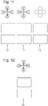
- Fig. 6 shows a perspective view of another arrangement of the low performance mass filter 8 not in accordance with the present invention.
- the mass filter 8 is configured and operates in the same manner as the mass filters described above, except that the electrodes 42-48 of the mass filter 8 need not comprise apertures 43 or recesses 52.
- Each of the rod electrodes 42-48 of the mass filter 8 is segmented in the longitudinal direction (z-direction), with gaps 60 between the axial segments of the rod set.
- the mass filter 8 is operated in the same way as described above, such that ions having mass to charge ratios outside of the first range are not stably confined and are radially excited to the extent that they are not transmitted by the mass filter 8.
- the gaps 60 reduce the surface area of the electrodes 42-48 on which the unstable ions may impact, thus reducing surface charging and contamination of these electrodes 42-48.
- the axial spacing between the electrode segments in the longitudinal direction (z-direction) may be chosen to be as large as possible and/or the thickness of the electrode segments in the longitudinal direction (z-direction) may be chosen to be as small as possible, provided that the required resolution of the mass filter 8 is maintained in order to minimise the surface area that can be contaminated by filtered ions.
- the electrodes 48-48 have circular cross-sections (in the x-y plane), other shapes may be used.
- the electrodes may be substantially hyperbolic (in the x-y plane), or they may have a substantially circular inner bore (e.g. may be annular).
- Figs. 4 and 5 may be axially segmented in the manner shown and described in relation to Fig. 6 in order to further reduce the contamination close to the ion optical axis of the mass filter 8.
- slotted apertures and/or grooved recesses in the electrodes of the mass filter 8 may have an impact on the analytical performance of a quadrupole mass filter, as it may reduce the transmission of ions of interest as the mass resolution is increased. However, at lower resolutions the transmission of the quadrupole is not significantly affected and hence this arrangement is suitable at least for use as the low resolution bandpass mass to charge ratio filter 8 used to protect the higher resolution analytical quadrupole mass filter 4.
- the instability of low mass to charge ratio ions within the RF-only pre-filter device 2 may not be as directional as in the case of a resolving quadrupole mass filter.
- slotted apertures and/or grooved recesses may be provided in such a pre-filter 2, or the pre-filter 2 may be segmented, so as to reduce the extent of surface contamination and decrease the effects of surface charging.
- An ion optical model (SIMION 8) was constructed in order to demonstrate the principal of operation of the instrument shown in Fig. 3 .
- the RF-only quadrupole filters 2 and 30, and the low resolution analytical quadrupole mass filter 8 were each 16 mm in length.
- the analytical quadrupole mass filter 4 was 130 mm in length. All of the rod electrodes had a radius of 6 mm and were arranged to form an inscribed circle of radius 5.33 mm.
- the frequency of the RF voltage applied to all of the rods was set to 1.185 MHz.
- the main analytical mass filter 4 was set to transmit a mass to charge ratio of 556. This corresponds to an RF amplitude of 1601.8 V (0-peak). The same amplitude of RF voltage was applied to the low resolution mass filter 8.
- the low resolution mass filter 8 was modeled non-tapered slotted apertures. Each of the slots either had a width in the x-direction or y-direction of 1 mm.
- the amplitude of the RF voltage applied to the RF-only filters 2 and 30 was set to 67% of the amplitude of the main analytical mass filter 4, i.e. 1073.2 V (0-pk).
- the kinetic energy of the ions entering the quadrupole assembly was modeled as 1 eV.
- a resolving DC voltage of 268.7 V was applied to the main analytical mass filter 4, resulting in a mass to charge ratio transmission window of approximately 0.5 Da.
- Plot 70 shows the relative transmission of ions having a mass to charge ratio of 556 for the arrangement of the prior art instrument shown in Fig. 1 .
- the three closely spaced plots 72,74,76 show the relative transmission for the embodiment of the invention shown in Fig. 3 .
- These transmission plots 72,74,76 were generated with the DC resolving voltage set for the low resolution mass filter 8 such that the theoretical resolution of this device was 80 Da, 40 Da and 20 Da respectively. No overall drop in ion transmission was observed for these settings.
- plot 78 shows the results for a theoretical transmission window of 10 amu on low resolution mass filter 8 and results in a reduction of 40-50% in transmission.
- Fig. 8 shows the position in z- and y- directions at which ions having a mass to charge ratio of 586 exit the radius of the inscribed circle bounded by quadrupoles 4,8 and 30 in Fig. 3 .
- the slotted, low-resolution mass filter 8 was set to transmit a mass to charge ratio range of 20 Da, centered at a mass to charge ratio of 556. It can be seen from Fig.
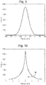
- Fig. 9 shows a histogram of the number of ions that travel in the y-direction and reach the surfaces of the rods of the low resolution mass filter 8, verses their position in the x-direction relative to the centres of the slots 43 in the rods.
- the data was modeled for ions having a mass to charge ratio of 1080 and under the same conditions as described in relation to Fig. 8 . It can be seen that the majority of the ions pass through the 1 mm wide slots in the rods and so will not contribute significantly to surface contamination on the rods.
- Fig. 10 shows a histogram 100 of the number of ions that travel in the y-direction and reach the surfaces of the rods of the pre-filter 2, verses their position in the x-direction relative to the centres of the rods; and shows a histogram of the number of ions 102 that travel in the x-direction and reach the surfaces of the rods of the pre-filter 2, verses their position in the y-direction relative to the centres of the rods.
- the data was modeled for ions having a mass to charge ratio of 184 and under the same conditions as described in relation to Fig. 8 . It can be seen from Fig. 10 that, although ejection is less directional than that for the resolving quadrupole shown in Fig.
- ions of this mass to charge ratio are ejected towards the rods in both the x- and y- dimensions. It can be seen that in this case a 2 mm wide slot in each of the pre-filter rods 2 would result in approximately 50% of the low mass ions passing through the slots, and hence not significantly contributing to surface contamination in the pre-filter 2. Even larger slots may be provided in this RF pre-filter 2 without significantly affecting the performance of the device, resulting in a further reduction in surface contamination.
- the RF-only pre-filter 30 does not have slotted apertures or grooved recesses in order that the entrance conditions to the main analytical mass filter 4 are maintained at ideal conditions for transmission and resolution of the main analytical mass filter 4.
- This pre-filter 30 may be maintained at the same RF amplitude as pre-filter 2. As such, there will be substantially no ions incident on the surfaces of the rod electrodes in pre-filter 30.
- the low performance mass filter 8 has been described as being used to protect and extend the operational lifetime of the higher performance analytical mass filter 4, the apparatus described may be used for many other applications where a low mass cut-off or mass to charge ratio band pass is required.
- Fig. 11 illustrates a low resolution band pass mass filter having reduced surface contamination characteristics not in accordance with the present invention.
- the instrument comprises a first RF-only filter 110 having longitudinal slotted apertures or grooved recesses of the type described above, followed by a low performance analytical mass filter 112 having slotted apertures or grooved recesses of the type described above, followed by a second RF-only mass filter 114 of the type describe above but having no slotted apertures or grooved recesses.
- This instrument may be used as a robust band pass filter, e.g. prior to another downstream analytical device other than, or in addition to, the main analytical mass filter 4 as previously described.
- the downstream analytical device may be an ion trap or time of flight mass analyser.
- the instrument of Fig. 11 may be used as a low performance robust band pass filter arranged downstream of a separate analytical device.
- the band pass filter may be arranged downstream of an ion mobility separator (IMS).
- IMS ion mobility separator
- the range of mass to charge ratios passed by the band pass filter may be fixed or may be scanned in synchronism with the delivery of ions from the upstream device.
- the band pass filter may be used to select ions eluting from an upstream IMS device corresponding to particular charge states. This may be achieved because ions of a given charge state tend to follow a relationship between ion mobility and mass to charge ratio, and the IMS device and band pass filter may be used in combination so as to only transmit ions following such a relationship.
- Fig. 12 shows a simple, robust low mass cut-off filter 120 not in accordance with the present invention.
- the filter comprises a set of RF-only quadrupole rods having longitudinal slots or grooves of the type described above for minimising surface contamination.
- This device may be used downstream of an IMS device, e.g. to prevent ions with certain ion mobility drift times and (e.g. maximum) mass to charge ratio values reaching a downstream mass analyser. This may be used to discriminate against ions with different charge states, since ions having the same charge state but different mass to charge ratios may be received at the filter, but only ions of one of the mass to charge ratio values may be transmitted.
- the slotted apertures and/or grooved recesses in the rods may be present over only part of the length of the rods, or may be present over the entire length of the rods.
- the presence of an RF-only pre-filter 2 upstream of the low resolution mass filter 8 may not be required for operation. This is because the mass filter 8 is operated at relatively low resolution and therefore the entrance conditions may not have a significant effect on transmission for ions at the centre of the mass to charge ratio transmission window. In this case, low mass to charge ratios may be ejected through one set of slotted apertures and high mass to charge ratios may be ejected through the other set of slotted apertures in the mass filter 8.
- the inscribed radii of the different rod sets may be different.
- Different DC voltages may be applied to the different rod sets so as to control the energy of the ions through each rod set.
- a dipole excitation voltage may be applied to the low resolution mass filter 8 and/or the RF-only filter 2 in order to help move ions in a direction towards the slotted apertures or recesses as the ions become unstable.
Landscapes
- Chemical & Material Sciences (AREA)
- Analytical Chemistry (AREA)
- Electron Tubes For Measurement (AREA)
- Other Investigation Or Analysis Of Materials By Electrical Means (AREA)
Claims (11)
- Verfahren zur Massenfilterung von Ionen, umfassend:Massenfilterung von Ionen unter Verwendung eines ersten Massenfilters (8), um massenselektiv nur Ionen durchzulassen, die einen ersten Bereich von Masse-zu-Ladung-Verhältnissen aufweisen; undMassenfilterung der von dem ersten Massenfilter (8) durchgelassenen Ionen unter Verwendung eines zweiten Massenfilters (4), wobei das zweite Massenfilter (4) nur Ionen durchlässt, die einen zweiten Bereich von Masse-zu-Ladungs-Verhältnissen aufweisen, der eine Teilmenge des ersten Bereichs von Masse-zu-Ladungs-Verhältnissen ist;wobei sich der erste Massenfilter und der zweite Massenfilter in einer einzigen Vakuumkammer befinden;dadurch gekennzeichnet, dass:mindestens eine Elektrode des ersten Massenfilters (8) eine sich vollständig durch die Elektrode erstreckende Öffnung umfasst und/oder eine sich nur teilweise durch die Elektrode erstreckende Aussparung umfasst, wobei die Öffnung und/oder Aussparung so angeordnet und konfiguriert ist, dass Ionen, die in dem ersten Massenfilter (8) instabil sind, in oder durch die Öffnung und/oder in die Aussparung gelangen, so dass sie nicht von dem ersten Massenfilter (8) durchgelassen werden; unddie von dem ersten Massenfilter (8) durchgelassenen Ionen in das zweite Massenfilter (4) geleitet werden, wobei ein reiner HF-Ionenleiter (30) verwendet wird, die zwischen dem ersten (8) und dem zweiten (4) Massenfilter angeordnet ist, wobei der reine HF-Ionenleiter (30) keine geschlitzten Öffnungen oder gerillten Vertiefungen umfasst, und wobei sich der reine HF-Ionenleiter (30) auch in der einzigen Vakuumkammer befindet.
- Verfahren nach Anspruch 1, wobei das erste Massenfilter (8) und/oder das zweite Massenfilter (4) ein Multipol-Massenfilter, wie z. B. ein Quadrupol-Massenfilter, ist.
- Verfahren nach Anspruch 1 oder 2, umfassend das Anlegen von Hochfrequenz- und Gleichspannungen an Elektroden des ersten Massenfilters (8) und/oder an Elektroden des zweiten Massenfilters (4), um Ionen, die durchgelassen werden sollen, zwischen den Elektroden einzuschließen und zu bewirken, dass Ionen, die nicht durchgelassen werden sollen, instabil sind und nicht zwischen den Elektroden eingeschlossen werden.
- Verfahren nach einem der vorstehenden Ansprüche, umfassend:
Leiten der Ionen in das erste Massenfilter (8) unter Verwendung eines zweiten lonenleiters (2), der stromaufwärts, optional direkt stromaufwärts, des ersten Massenfilters (8) angeordnet ist; optional, wobei der zweite lonenleiter (2) ein reiner RFlonenleiter ist, an den nur RF-Potentiale und keine DC-Potentiale angelegt werden. - Verfahren nach einem der vorstehenden Ansprüche, wobei mindestens eine der Elektroden des zweiten Massenfilters (4) und/oder mindestens eine der Elektroden des ersten lonenleiters (30) und/oder mindestens eine der Elektroden des zweiten lonenleiters (2) eine Öffnung umfasst, die sich vollständig durch die Elektrode erstreckt, und/oder eine Aussparung umfasst, die sich nur teilweise durch die Elektrode erstreckt, wobei die Öffnung und/oder die Aussparung so angeordnet und konfiguriert ist, dass Ionen, die in dem zweiten Massenfilter (4) oder dem lonenleiter (2, 30) instabil sind, in oder durch die Öffnung und/oder in die Aussparung gelangen, so dass sie nicht von dem zweiten Massenfilter (4) oder dem lonenleiter (2, 30) durchgelassen werden.
- Verfahren nach einem der vorstehenden Ansprüche, wobei die Elektrode, die die Öffnung oder Aussparung aufweist, in einer Richtung entlang der Länge des Massenfilters oder lonenleiters langgestreckt ist, und wobei die Öffnung eine geschlitzte Öffnung oder die Aussparung eine geschlitzte Aussparung ist.
- Verfahren nach einem der vorstehenden Ansprüche, umfassend das Anordnen eines leitenden Gitters oder Netzes über oder in der Öffnung oder Vertiefung, um ein von der Elektrode erzeugtes elektrisches Feld zu unterstützen.
- Verfahren nach einem der vorstehenden Ansprüche, wobei Ionen, die in oder durch die Öffnung oder Aussparung gelangen, nicht erfasst und neutralisiert oder verworfen werden.
- Verfahren nach einem der vorstehenden Ansprüche, wobei mindestens einige der Elektroden des ersten Massenfilters (8) und/oder des zweiten lonenleiters (2) beheizt werden.
- Verfahren zur Massenspektrometrie und/oder lonenmobilitätsspektrometrie, umfassend ein Verfahren nach einem der vorstehenden Ansprüche, weiter umfassend das Erfassen von Ionen, die von den Massenfiltern durchgelassen werden, und/oder das Analysieren von Ionen, die von den Massenfiltern durchgelassen werden, und/oder das Analysieren von Ionen, die von den Massenfiltern durchgelassen werden, hinsichtlich ihrer lonenmobilität.
- Massen- und/oder lonenmobilitätsspektrometer, umfassend:einen ersten Massenfilter (8), der eine Vielzahl von Elektroden umfasst;einen zweiten Massenfilter (4), der eine Vielzahl von Elektroden umfasst, die stromabwärts des ersten Massenfilters (8) angeordnet sind, um die von dem ersten Massenfilter (8) durchgelassenen Ionen zu empfangen;eine oder mehrere Spannungsversorgungen (14, 16, 18, 20, 32); undeine Steuerung (24), die eingerichtet und konfiguriert ist zum:Steuern der einen oder mehreren Spannungsversorgungen (14, 16), um Spannungen an den ersten Massenfilter (8) anzulegen, so dass er massenselektiv nur Ionen durchlässt, die einen ersten Bereich von Masse-zu-Ladungs-Verhältnissen aufweisen; undSteuern der einen oder mehreren Spannungsversorgungen (18, 20), um Spannungen an den zweiten Massenfilter (4) anzulegen, so dass der die vom ersten Massenfilter (8) durchgelassenen Ionen massenfiltert, und so, dass der zweite Massenfilter (4) nur Ionen, die einen zweiten Bereich von Masse-zu-Ladungs-Verhältnissen aufweisen, der eine Untermenge des ersten Bereichs von Masse-zu-Ladungs-Verhältnissen ist;
wobei sich der erste Massenfilter und der zweite Massenfilter in einer einzigen Vakuumkammer befinden;dadurch gekennzeichnet, dass:mindestens eine der Elektroden des ersten Massenfilters (8) eine sich vollständig durch die Elektrode erstreckende Öffnung umfasst und/oder eine sich nur teilweise durch die Elektrode erstreckende Aussparung umfasst, wobei die Öffnung und/oder Aussparung so angeordnet und konfiguriert ist, dass, wenn die Spannungen an den ersten Massenfilter (8) angelegt werden, Ionen in dem ersten Massenfilter (8) instabil werden und in oder durch die Öffnung und/oder in die Aussparung gelangen, so dass sie nicht von dem ersten Massenfilter (8) zu dem zweiten Massenfilter (4) durchgelassen werden; undein reiner HF-Ionenleiter (30) zwischen dem ersten (8) und dem zweiten (4) Massenfilter angeordnet ist, um die von dem ersten Massenfilter (8) durchgelassenen Ionen in den zweiten Massenfilter (4) zu leiten, wobei der reine HF-Ionenleiter (30) keine geschlitzten Öffnungen oder gerillten Vertiefungen umfasst und wobei sich der reine HF-Ionenleiter (30) auch in der einzigen Vakuumkammer befindet.
Applications Claiming Priority (2)
| Application Number | Priority Date | Filing Date | Title |
|---|---|---|---|
| GBGB1509243.0A GB201509243D0 (en) | 2015-05-29 | 2015-05-29 | Mass filter having extended operational lifetime |
| PCT/GB2016/051581 WO2016193701A1 (en) | 2015-05-29 | 2016-05-31 | Mass filter having extended operational lifetime |
Publications (2)
| Publication Number | Publication Date |
|---|---|
| EP3304577A1 EP3304577A1 (de) | 2018-04-11 |
| EP3304577B1 true EP3304577B1 (de) | 2022-08-10 |
Family
ID=53677404
Family Applications (1)
| Application Number | Title | Priority Date | Filing Date |
|---|---|---|---|
| EP16727783.9A Active EP3304577B1 (de) | 2015-05-29 | 2016-05-31 | Massenfilter mit verlängerter lebensdauer |
Country Status (6)
| Country | Link |
|---|---|
| US (2) | US10453667B2 (de) |
| EP (1) | EP3304577B1 (de) |
| JP (1) | JP6746617B2 (de) |
| CN (1) | CN107667414B (de) |
| GB (2) | GB201509243D0 (de) |
| WO (1) | WO2016193701A1 (de) |
Families Citing this family (13)
| Publication number | Priority date | Publication date | Assignee | Title |
|---|---|---|---|---|
| EP3357080B1 (de) * | 2015-10-01 | 2024-05-01 | DH Technologies Development PTE. Ltd. | Masse-selektive lineare ionenfalle mit axialem auswurf |
| GB2563565B (en) * | 2017-04-13 | 2022-05-11 | Micromass Ltd | Mass spectrometry with increased duty cycle |
| EP3895205A1 (de) | 2018-12-13 | 2021-10-20 | DH Technologies Development Pte. Ltd. | Effektive potenzialanpassung an grenzen von segmentierten quadrupolen in einem massenspektrometer |
| GB2583092B (en) | 2019-04-15 | 2021-09-22 | Thermo Fisher Scient Bremen Gmbh | Mass spectrometer having improved quadrupole robustness |
| GB201907332D0 (en) | 2019-05-24 | 2019-07-10 | Micromass Ltd | Mass filter having reduced contamination |
| GB201914451D0 (en) * | 2019-10-07 | 2019-11-20 | Micromass Ltd | Automatically standardising spectrometers |
| US10957524B1 (en) * | 2019-11-14 | 2021-03-23 | Thermo Finnigan Llc | Multipole assembly with galvanic protection for use in a mass spectrometer |
| JP7762203B2 (ja) * | 2020-11-19 | 2025-10-29 | ディーエイチ テクノロジーズ デベロップメント プライベート リミテッド | 質量分析の堅牢性を強化するためにバンドパスフィルタリング衝突セルを使用して高強度イオンビームのms/msを実施する方法 |
| KR20240090158A (ko) | 2021-10-01 | 2024-06-21 | 샤인 테크놀로지스 엘엘씨 | 이온 수집을 위한 섬유질 격자를 갖는 이온 생성 시스템 |
| WO2024161152A1 (en) * | 2023-02-03 | 2024-08-08 | Micromass Uk Limited | Mass filter |
| GB2630318B (en) | 2023-05-23 | 2025-07-23 | Thermo Fisher Scient Bremen Gmbh | Method of operating a multipole device |
| GB202307689D0 (en) | 2023-05-23 | 2023-07-05 | Thermo Fisher Scient Bremen Gmbh | Method for reducing charge and ion optical system |
| JP2024176517A (ja) * | 2023-06-08 | 2024-12-19 | 株式会社日立ハイテク | イオンガイド及び質量分析計 |
Citations (1)
| Publication number | Priority date | Publication date | Assignee | Title |
|---|---|---|---|---|
| WO2014197348A2 (en) * | 2013-06-03 | 2014-12-11 | Perkinelmer Health Sciences, Inc. | Ion guide or filters with selected gas conductance |
Family Cites Families (22)
| Publication number | Priority date | Publication date | Assignee | Title |
|---|---|---|---|---|
| US3473020A (en) * | 1967-06-19 | 1969-10-14 | Bell & Howell Co | Mass analyzer having series aligned curvilinear and rectilinear analyzer sections |
| US5525084A (en) * | 1994-03-25 | 1996-06-11 | Hewlett Packard Company | Universal quadrupole and method of manufacture |
| JP3495512B2 (ja) * | 1996-07-02 | 2004-02-09 | 株式会社日立製作所 | イオントラップ質量分析装置 |
| US5783824A (en) | 1995-04-03 | 1998-07-21 | Hitachi, Ltd. | Ion trapping mass spectrometry apparatus |
| JP3346688B2 (ja) | 1995-09-13 | 2002-11-18 | 日本原子力研究所 | 四極子質量分析計 |
| JP4018186B2 (ja) | 1997-01-30 | 2007-12-05 | アロカ株式会社 | 同位体分析装置 |
| JP3570151B2 (ja) | 1997-04-17 | 2004-09-29 | 株式会社日立製作所 | イオントラップ質量分析装置 |
| US6140638A (en) | 1997-06-04 | 2000-10-31 | Mds Inc. | Bandpass reactive collision cell |
| US7060972B2 (en) * | 2000-07-21 | 2006-06-13 | Mds Inc. | Triple quadrupole mass spectrometer with capability to perform multiple mass analysis steps |
| GB0210930D0 (en) * | 2002-05-13 | 2002-06-19 | Thermo Electron Corp | Improved mass spectrometer and mass filters therefor |
| CA2540584C (en) * | 2003-10-08 | 2012-04-03 | Varian Australia Pty Ltd | Electrode for mass spectrometry |
| GB0514964D0 (en) * | 2005-07-21 | 2005-08-24 | Ms Horizons Ltd | Mass spectrometer devices & methods of performing mass spectrometry |
| CA2595631C (en) * | 2005-01-17 | 2014-04-22 | Micromass Uk Limited | Mass spectrometer |
| GB0511333D0 (en) | 2005-06-03 | 2005-07-13 | Micromass Ltd | Mass spectrometer |
| GB0703378D0 (en) * | 2007-02-21 | 2007-03-28 | Micromass Ltd | Mass spectrometer |
| CA2699682C (en) * | 2007-09-19 | 2017-05-30 | Dh Technologies Development Pte. Ltd. | Collision cell for mass spectrometer |
| GB0800526D0 (en) * | 2008-01-11 | 2008-02-20 | Micromass Ltd | Mass spectrometer |
| US7947948B2 (en) * | 2008-09-05 | 2011-05-24 | Thermo Funnigan LLC | Two-dimensional radial-ejection ion trap operable as a quadrupole mass filter |
| WO2015092399A1 (en) * | 2013-12-19 | 2015-06-25 | Micromass Uk Limited | High pressure mass resolving ion guide with axial field |
| GB201322515D0 (en) * | 2013-12-19 | 2014-02-05 | Micromass Ltd | High pressure mass resolving ion guide with axial field |
| US9613788B2 (en) * | 2014-06-13 | 2017-04-04 | Perkinelmer Health Sciences, Inc. | RF ion guide with axial fields |
| US9312113B1 (en) * | 2014-12-09 | 2016-04-12 | Bruker Daltonics, Inc. | Contamination-proof ion guide for mass spectrometry |
-
2015
- 2015-05-29 GB GBGB1509243.0A patent/GB201509243D0/en not_active Ceased
-
2016
- 2016-05-31 WO PCT/GB2016/051581 patent/WO2016193701A1/en not_active Ceased
- 2016-05-31 JP JP2017561933A patent/JP6746617B2/ja active Active
- 2016-05-31 US US15/578,053 patent/US10453667B2/en active Active
- 2016-05-31 GB GB1719150.3A patent/GB2555032B/en active Active
- 2016-05-31 EP EP16727783.9A patent/EP3304577B1/de active Active
- 2016-05-31 CN CN201680031211.9A patent/CN107667414B/zh active Active
-
2019
- 2019-09-06 US US16/563,203 patent/US10832900B2/en active Active
Patent Citations (1)
| Publication number | Priority date | Publication date | Assignee | Title |
|---|---|---|---|---|
| WO2014197348A2 (en) * | 2013-06-03 | 2014-12-11 | Perkinelmer Health Sciences, Inc. | Ion guide or filters with selected gas conductance |
Non-Patent Citations (1)
| Title |
|---|
| "Introduction to mass spectrometry : instrumentation, applications, and strategies for data interpretation", 1 January 2007, WILEY, Chichester [u.a], ISBN: 978-0-470-51634-8, article J THROCK WATSON ET AL: "John Wiley & Sons, Ltd INTRODUCTION TO MASS SPECTROMETRY", pages: 53 - 172, XP055389637 * |
Also Published As
| Publication number | Publication date |
|---|---|
| GB201719150D0 (en) | 2018-01-03 |
| JP6746617B2 (ja) | 2020-08-26 |
| CN107667414B (zh) | 2020-05-29 |
| GB2555032B (en) | 2021-08-04 |
| GB201509243D0 (en) | 2015-07-15 |
| GB2555032A (en) | 2018-04-18 |
| CN107667414A (zh) | 2018-02-06 |
| JP2018517254A (ja) | 2018-06-28 |
| US10453667B2 (en) | 2019-10-22 |
| EP3304577A1 (de) | 2018-04-11 |
| US20180174817A1 (en) | 2018-06-21 |
| US20200075308A1 (en) | 2020-03-05 |
| WO2016193701A1 (en) | 2016-12-08 |
| US10832900B2 (en) | 2020-11-10 |
Similar Documents
| Publication | Publication Date | Title |
|---|---|---|
| US10832900B2 (en) | Mass filter having extended operational lifetime | |
| EP2965075B2 (de) | Optimierte ionenmobilitäts-abscheidungszeitpunkte für angezielte ionen | |
| US10811244B2 (en) | Method of separating ions | |
| US10134574B2 (en) | Pre-filter fragmentation | |
| US11488815B2 (en) | Trap fill time dynamic range enhancment | |
| EP3005398B1 (de) | Verfahren und vorrichtung zur reaktion von ionen | |
| EP3504727B1 (de) | Steuerung der ionentemperatur bei einem ionenleiter | |
| EP2956957B1 (de) | Verbesserte wirksamkeit und präzise steuerung von gasphasenreaktionen in massenspektrometern unter verwendung einer autoausgabe-ionenfalle | |
| EP3069376B1 (de) | Verfahren zur isolierung von ionen | |
| US9929002B2 (en) | High pressure mass resolving ion guide with axial field | |
| US11114291B2 (en) | Method of separating different ions having similar mass to charge ratios | |
| US10497551B2 (en) | Storage ring for fast processes | |
| US10153147B2 (en) | Method of compressing an ion beam | |
| GB2512474A (en) | Device allowing improved reaction monitoring of gas phase reactions in mass spectrometers using an auto ejection ion trap | |
| GB2526895A (en) | Storage ring for fast processes |
Legal Events
| Date | Code | Title | Description |
|---|---|---|---|
| STAA | Information on the status of an ep patent application or granted ep patent |
Free format text: STATUS: THE INTERNATIONAL PUBLICATION HAS BEEN MADE |
|
| PUAI | Public reference made under article 153(3) epc to a published international application that has entered the european phase |
Free format text: ORIGINAL CODE: 0009012 |
|
| STAA | Information on the status of an ep patent application or granted ep patent |
Free format text: STATUS: REQUEST FOR EXAMINATION WAS MADE |
|
| 17P | Request for examination filed |
Effective date: 20171120 |
|
| AK | Designated contracting states |
Kind code of ref document: A1 Designated state(s): AL AT BE BG CH CY CZ DE DK EE ES FI FR GB GR HR HU IE IS IT LI LT LU LV MC MK MT NL NO PL PT RO RS SE SI SK SM TR |
|
| AX | Request for extension of the european patent |
Extension state: BA ME |
|
| DAV | Request for validation of the european patent (deleted) | ||
| DAX | Request for extension of the european patent (deleted) | ||
| STAA | Information on the status of an ep patent application or granted ep patent |
Free format text: STATUS: EXAMINATION IS IN PROGRESS |
|
| 17Q | First examination report despatched |
Effective date: 20200212 |
|
| GRAP | Despatch of communication of intention to grant a patent |
Free format text: ORIGINAL CODE: EPIDOSNIGR1 |
|
| STAA | Information on the status of an ep patent application or granted ep patent |
Free format text: STATUS: GRANT OF PATENT IS INTENDED |
|
| INTG | Intention to grant announced |
Effective date: 20220310 |
|
| RAP3 | Party data changed (applicant data changed or rights of an application transferred) |
Owner name: MICROMASS UK LIMITED |
|
| GRAS | Grant fee paid |
Free format text: ORIGINAL CODE: EPIDOSNIGR3 |
|
| GRAA | (expected) grant |
Free format text: ORIGINAL CODE: 0009210 |
|
| STAA | Information on the status of an ep patent application or granted ep patent |
Free format text: STATUS: THE PATENT HAS BEEN GRANTED |
|
| AK | Designated contracting states |
Kind code of ref document: B1 Designated state(s): AL AT BE BG CH CY CZ DE DK EE ES FI FR GR HR HU IE IS IT LI LT LU LV MC MK MT NL NO PL PT RO RS SE SI SK SM TR |
|
| RBV | Designated contracting states (corrected) |
Designated state(s): AL AT BE BG CH CY CZ DE DK EE ES FI FR GR HR HU IE IS IT LI LT LU LV MC MK MT NL NO PL PT RO RS SE SI SK SM TR |
|
| REG | Reference to a national code |
Ref country code: AT Ref legal event code: REF Ref document number: 1511173 Country of ref document: AT Kind code of ref document: T Effective date: 20220815 Ref country code: CH Ref legal event code: EP |
|
| REG | Reference to a national code |
Ref country code: DE Ref legal event code: R096 Ref document number: 602016074133 Country of ref document: DE |
|
| REG | Reference to a national code |
Ref country code: IE Ref legal event code: FG4D |
|
| REG | Reference to a national code |
Ref country code: NL Ref legal event code: MP Effective date: 20220810 |
|
| REG | Reference to a national code |
Ref country code: LT Ref legal event code: MG9D |
|
| PG25 | Lapsed in a contracting state [announced via postgrant information from national office to epo] |
Ref country code: SE Free format text: LAPSE BECAUSE OF FAILURE TO SUBMIT A TRANSLATION OF THE DESCRIPTION OR TO PAY THE FEE WITHIN THE PRESCRIBED TIME-LIMIT Effective date: 20220810 Ref country code: RS Free format text: LAPSE BECAUSE OF FAILURE TO SUBMIT A TRANSLATION OF THE DESCRIPTION OR TO PAY THE FEE WITHIN THE PRESCRIBED TIME-LIMIT Effective date: 20220810 Ref country code: PT Free format text: LAPSE BECAUSE OF FAILURE TO SUBMIT A TRANSLATION OF THE DESCRIPTION OR TO PAY THE FEE WITHIN THE PRESCRIBED TIME-LIMIT Effective date: 20221212 Ref country code: NO Free format text: LAPSE BECAUSE OF FAILURE TO SUBMIT A TRANSLATION OF THE DESCRIPTION OR TO PAY THE FEE WITHIN THE PRESCRIBED TIME-LIMIT Effective date: 20221110 Ref country code: NL Free format text: LAPSE BECAUSE OF FAILURE TO SUBMIT A TRANSLATION OF THE DESCRIPTION OR TO PAY THE FEE WITHIN THE PRESCRIBED TIME-LIMIT Effective date: 20220810 Ref country code: LV Free format text: LAPSE BECAUSE OF FAILURE TO SUBMIT A TRANSLATION OF THE DESCRIPTION OR TO PAY THE FEE WITHIN THE PRESCRIBED TIME-LIMIT Effective date: 20220810 Ref country code: LT Free format text: LAPSE BECAUSE OF FAILURE TO SUBMIT A TRANSLATION OF THE DESCRIPTION OR TO PAY THE FEE WITHIN THE PRESCRIBED TIME-LIMIT Effective date: 20220810 Ref country code: FI Free format text: LAPSE BECAUSE OF FAILURE TO SUBMIT A TRANSLATION OF THE DESCRIPTION OR TO PAY THE FEE WITHIN THE PRESCRIBED TIME-LIMIT Effective date: 20220810 Ref country code: ES Free format text: LAPSE BECAUSE OF FAILURE TO SUBMIT A TRANSLATION OF THE DESCRIPTION OR TO PAY THE FEE WITHIN THE PRESCRIBED TIME-LIMIT Effective date: 20220810 |
|
| REG | Reference to a national code |
Ref country code: AT Ref legal event code: MK05 Ref document number: 1511173 Country of ref document: AT Kind code of ref document: T Effective date: 20220810 |
|
| PG25 | Lapsed in a contracting state [announced via postgrant information from national office to epo] |
Ref country code: PL Free format text: LAPSE BECAUSE OF FAILURE TO SUBMIT A TRANSLATION OF THE DESCRIPTION OR TO PAY THE FEE WITHIN THE PRESCRIBED TIME-LIMIT Effective date: 20220810 Ref country code: IS Free format text: LAPSE BECAUSE OF FAILURE TO SUBMIT A TRANSLATION OF THE DESCRIPTION OR TO PAY THE FEE WITHIN THE PRESCRIBED TIME-LIMIT Effective date: 20221210 Ref country code: HR Free format text: LAPSE BECAUSE OF FAILURE TO SUBMIT A TRANSLATION OF THE DESCRIPTION OR TO PAY THE FEE WITHIN THE PRESCRIBED TIME-LIMIT Effective date: 20220810 Ref country code: GR Free format text: LAPSE BECAUSE OF FAILURE TO SUBMIT A TRANSLATION OF THE DESCRIPTION OR TO PAY THE FEE WITHIN THE PRESCRIBED TIME-LIMIT Effective date: 20221111 |
|
| PG25 | Lapsed in a contracting state [announced via postgrant information from national office to epo] |
Ref country code: SM Free format text: LAPSE BECAUSE OF FAILURE TO SUBMIT A TRANSLATION OF THE DESCRIPTION OR TO PAY THE FEE WITHIN THE PRESCRIBED TIME-LIMIT Effective date: 20220810 Ref country code: RO Free format text: LAPSE BECAUSE OF FAILURE TO SUBMIT A TRANSLATION OF THE DESCRIPTION OR TO PAY THE FEE WITHIN THE PRESCRIBED TIME-LIMIT Effective date: 20220810 Ref country code: DK Free format text: LAPSE BECAUSE OF FAILURE TO SUBMIT A TRANSLATION OF THE DESCRIPTION OR TO PAY THE FEE WITHIN THE PRESCRIBED TIME-LIMIT Effective date: 20220810 Ref country code: CZ Free format text: LAPSE BECAUSE OF FAILURE TO SUBMIT A TRANSLATION OF THE DESCRIPTION OR TO PAY THE FEE WITHIN THE PRESCRIBED TIME-LIMIT Effective date: 20220810 Ref country code: AT Free format text: LAPSE BECAUSE OF FAILURE TO SUBMIT A TRANSLATION OF THE DESCRIPTION OR TO PAY THE FEE WITHIN THE PRESCRIBED TIME-LIMIT Effective date: 20220810 |
|
| REG | Reference to a national code |
Ref country code: DE Ref legal event code: R097 Ref document number: 602016074133 Country of ref document: DE |
|
| PG25 | Lapsed in a contracting state [announced via postgrant information from national office to epo] |
Ref country code: SK Free format text: LAPSE BECAUSE OF FAILURE TO SUBMIT A TRANSLATION OF THE DESCRIPTION OR TO PAY THE FEE WITHIN THE PRESCRIBED TIME-LIMIT Effective date: 20220810 Ref country code: EE Free format text: LAPSE BECAUSE OF FAILURE TO SUBMIT A TRANSLATION OF THE DESCRIPTION OR TO PAY THE FEE WITHIN THE PRESCRIBED TIME-LIMIT Effective date: 20220810 |
|
| P01 | Opt-out of the competence of the unified patent court (upc) registered |
Effective date: 20230509 |
|
| PLBE | No opposition filed within time limit |
Free format text: ORIGINAL CODE: 0009261 |
|
| STAA | Information on the status of an ep patent application or granted ep patent |
Free format text: STATUS: NO OPPOSITION FILED WITHIN TIME LIMIT |
|
| PG25 | Lapsed in a contracting state [announced via postgrant information from national office to epo] |
Ref country code: AL Free format text: LAPSE BECAUSE OF FAILURE TO SUBMIT A TRANSLATION OF THE DESCRIPTION OR TO PAY THE FEE WITHIN THE PRESCRIBED TIME-LIMIT Effective date: 20220810 |
|
| 26N | No opposition filed |
Effective date: 20230511 |
|
| PG25 | Lapsed in a contracting state [announced via postgrant information from national office to epo] |
Ref country code: SI Free format text: LAPSE BECAUSE OF FAILURE TO SUBMIT A TRANSLATION OF THE DESCRIPTION OR TO PAY THE FEE WITHIN THE PRESCRIBED TIME-LIMIT Effective date: 20220810 |
|
| REG | Reference to a national code |
Ref country code: CH Ref legal event code: PL |
|
| PG25 | Lapsed in a contracting state [announced via postgrant information from national office to epo] |
Ref country code: MC Free format text: LAPSE BECAUSE OF FAILURE TO SUBMIT A TRANSLATION OF THE DESCRIPTION OR TO PAY THE FEE WITHIN THE PRESCRIBED TIME-LIMIT Effective date: 20220810 |
|
| REG | Reference to a national code |
Ref country code: BE Ref legal event code: MM Effective date: 20230531 |
|
| PG25 | Lapsed in a contracting state [announced via postgrant information from national office to epo] |
Ref country code: MC Free format text: LAPSE BECAUSE OF FAILURE TO SUBMIT A TRANSLATION OF THE DESCRIPTION OR TO PAY THE FEE WITHIN THE PRESCRIBED TIME-LIMIT Effective date: 20220810 Ref country code: LU Free format text: LAPSE BECAUSE OF NON-PAYMENT OF DUE FEES Effective date: 20230531 Ref country code: LI Free format text: LAPSE BECAUSE OF NON-PAYMENT OF DUE FEES Effective date: 20230531 Ref country code: CH Free format text: LAPSE BECAUSE OF NON-PAYMENT OF DUE FEES Effective date: 20230531 |
|
| REG | Reference to a national code |
Ref country code: IE Ref legal event code: MM4A |
|
| PG25 | Lapsed in a contracting state [announced via postgrant information from national office to epo] |
Ref country code: IE Free format text: LAPSE BECAUSE OF NON-PAYMENT OF DUE FEES Effective date: 20230531 |
|
| PG25 | Lapsed in a contracting state [announced via postgrant information from national office to epo] |
Ref country code: IE Free format text: LAPSE BECAUSE OF NON-PAYMENT OF DUE FEES Effective date: 20230531 |
|
| PG25 | Lapsed in a contracting state [announced via postgrant information from national office to epo] |
Ref country code: IT Free format text: LAPSE BECAUSE OF FAILURE TO SUBMIT A TRANSLATION OF THE DESCRIPTION OR TO PAY THE FEE WITHIN THE PRESCRIBED TIME-LIMIT Effective date: 20220810 Ref country code: FR Free format text: LAPSE BECAUSE OF NON-PAYMENT OF DUE FEES Effective date: 20230531 Ref country code: BE Free format text: LAPSE BECAUSE OF NON-PAYMENT OF DUE FEES Effective date: 20230531 |
|
| PG25 | Lapsed in a contracting state [announced via postgrant information from national office to epo] |
Ref country code: BG Free format text: LAPSE BECAUSE OF FAILURE TO SUBMIT A TRANSLATION OF THE DESCRIPTION OR TO PAY THE FEE WITHIN THE PRESCRIBED TIME-LIMIT Effective date: 20220810 |
|
| PG25 | Lapsed in a contracting state [announced via postgrant information from national office to epo] |
Ref country code: BG Free format text: LAPSE BECAUSE OF FAILURE TO SUBMIT A TRANSLATION OF THE DESCRIPTION OR TO PAY THE FEE WITHIN THE PRESCRIBED TIME-LIMIT Effective date: 20220810 |
|
| PGFP | Annual fee paid to national office [announced via postgrant information from national office to epo] |
Ref country code: DE Payment date: 20250423 Year of fee payment: 10 |
|
| PG25 | Lapsed in a contracting state [announced via postgrant information from national office to epo] |
Ref country code: CY Free format text: LAPSE BECAUSE OF FAILURE TO SUBMIT A TRANSLATION OF THE DESCRIPTION OR TO PAY THE FEE WITHIN THE PRESCRIBED TIME-LIMIT; INVALID AB INITIO Effective date: 20160531 |
|
| PG25 | Lapsed in a contracting state [announced via postgrant information from national office to epo] |
Ref country code: HU Free format text: LAPSE BECAUSE OF FAILURE TO SUBMIT A TRANSLATION OF THE DESCRIPTION OR TO PAY THE FEE WITHIN THE PRESCRIBED TIME-LIMIT; INVALID AB INITIO Effective date: 20160531 |
|
| PG25 | Lapsed in a contracting state [announced via postgrant information from national office to epo] |
Ref country code: TR Free format text: LAPSE BECAUSE OF FAILURE TO SUBMIT A TRANSLATION OF THE DESCRIPTION OR TO PAY THE FEE WITHIN THE PRESCRIBED TIME-LIMIT Effective date: 20220810 |