EP3304301B1 - Bandwidth/resource management for multithreaded processors - Google Patents
Bandwidth/resource management for multithreaded processors Download PDFInfo
- Publication number
- EP3304301B1 EP3304301B1 EP16722472.4A EP16722472A EP3304301B1 EP 3304301 B1 EP3304301 B1 EP 3304301B1 EP 16722472 A EP16722472 A EP 16722472A EP 3304301 B1 EP3304301 B1 EP 3304301B1
- Authority
- EP
- European Patent Office
- Prior art keywords
- threads
- thread
- danger
- priority
- udm
- Prior art date
- Legal status (The legal status is an assumption and is not a legal conclusion. Google has not performed a legal analysis and makes no representation as to the accuracy of the status listed.)
- Active
Links
- 238000012545 processing Methods 0.000 claims description 51
- 238000000034 method Methods 0.000 claims description 39
- 230000008569 process Effects 0.000 claims description 8
- GVVPGTZRZFNKDS-JXMROGBWSA-N geranyl diphosphate Chemical compound CC(C)=CCC\C(C)=C\CO[P@](O)(=O)OP(O)(O)=O GVVPGTZRZFNKDS-JXMROGBWSA-N 0.000 claims 1
- 230000006870 function Effects 0.000 description 13
- 238000012546 transfer Methods 0.000 description 10
- 230000008859 change Effects 0.000 description 6
- 238000001514 detection method Methods 0.000 description 6
- 238000010586 diagram Methods 0.000 description 6
- 230000009471 action Effects 0.000 description 4
- 230000015556 catabolic process Effects 0.000 description 4
- 238000006731 degradation reaction Methods 0.000 description 4
- 230000005540 biological transmission Effects 0.000 description 2
- 238000004891 communication Methods 0.000 description 2
- 230000007423 decrease Effects 0.000 description 2
- 230000003111 delayed effect Effects 0.000 description 2
- 230000007246 mechanism Effects 0.000 description 2
- 239000002245 particle Substances 0.000 description 2
- 230000002093 peripheral effect Effects 0.000 description 2
- 238000000926 separation method Methods 0.000 description 2
- 238000007493 shaping process Methods 0.000 description 2
- 208000003028 Stuttering Diseases 0.000 description 1
- 230000002776 aggregation Effects 0.000 description 1
- 238000004220 aggregation Methods 0.000 description 1
- 230000008901 benefit Effects 0.000 description 1
- 239000000872 buffer Substances 0.000 description 1
- 230000001413 cellular effect Effects 0.000 description 1
- 238000012508 change request Methods 0.000 description 1
- 230000003247 decreasing effect Effects 0.000 description 1
- 238000012217 deletion Methods 0.000 description 1
- 230000037430 deletion Effects 0.000 description 1
- 238000013461 design Methods 0.000 description 1
- 238000005516 engineering process Methods 0.000 description 1
- 239000004744 fabric Substances 0.000 description 1
- 238000003780 insertion Methods 0.000 description 1
- 230000037431 insertion Effects 0.000 description 1
- 230000003287 optical effect Effects 0.000 description 1
- 230000008520 organization Effects 0.000 description 1
- 230000011664 signaling Effects 0.000 description 1
- 239000007787 solid Substances 0.000 description 1
- 230000003068 static effect Effects 0.000 description 1
- 230000001960 triggered effect Effects 0.000 description 1
Images


Classifications
-
- G—PHYSICS
- G06—COMPUTING; CALCULATING OR COUNTING
- G06F—ELECTRIC DIGITAL DATA PROCESSING
- G06F9/00—Arrangements for program control, e.g. control units
- G06F9/06—Arrangements for program control, e.g. control units using stored programs, i.e. using an internal store of processing equipment to receive or retain programs
- G06F9/46—Multiprogramming arrangements
-
- G—PHYSICS
- G06—COMPUTING; CALCULATING OR COUNTING
- G06F—ELECTRIC DIGITAL DATA PROCESSING
- G06F11/00—Error detection; Error correction; Monitoring
- G06F11/07—Responding to the occurrence of a fault, e.g. fault tolerance
- G06F11/0703—Error or fault processing not based on redundancy, i.e. by taking additional measures to deal with the error or fault not making use of redundancy in operation, in hardware, or in data representation
- G06F11/0706—Error or fault processing not based on redundancy, i.e. by taking additional measures to deal with the error or fault not making use of redundancy in operation, in hardware, or in data representation the processing taking place on a specific hardware platform or in a specific software environment
- G06F11/0721—Error or fault processing not based on redundancy, i.e. by taking additional measures to deal with the error or fault not making use of redundancy in operation, in hardware, or in data representation the processing taking place on a specific hardware platform or in a specific software environment within a central processing unit [CPU]
- G06F11/0724—Error or fault processing not based on redundancy, i.e. by taking additional measures to deal with the error or fault not making use of redundancy in operation, in hardware, or in data representation the processing taking place on a specific hardware platform or in a specific software environment within a central processing unit [CPU] in a multiprocessor or a multi-core unit
-
- G—PHYSICS
- G06—COMPUTING; CALCULATING OR COUNTING
- G06F—ELECTRIC DIGITAL DATA PROCESSING
- G06F11/00—Error detection; Error correction; Monitoring
- G06F11/07—Responding to the occurrence of a fault, e.g. fault tolerance
- G06F11/0703—Error or fault processing not based on redundancy, i.e. by taking additional measures to deal with the error or fault not making use of redundancy in operation, in hardware, or in data representation
- G06F11/0751—Error or fault detection not based on redundancy
- G06F11/0754—Error or fault detection not based on redundancy by exceeding limits
-
- G—PHYSICS
- G06—COMPUTING; CALCULATING OR COUNTING
- G06F—ELECTRIC DIGITAL DATA PROCESSING
- G06F11/00—Error detection; Error correction; Monitoring
- G06F11/07—Responding to the occurrence of a fault, e.g. fault tolerance
- G06F11/0703—Error or fault processing not based on redundancy, i.e. by taking additional measures to deal with the error or fault not making use of redundancy in operation, in hardware, or in data representation
- G06F11/079—Root cause analysis, i.e. error or fault diagnosis
-
- G—PHYSICS
- G06—COMPUTING; CALCULATING OR COUNTING
- G06F—ELECTRIC DIGITAL DATA PROCESSING
- G06F9/00—Arrangements for program control, e.g. control units
- G06F9/06—Arrangements for program control, e.g. control units using stored programs, i.e. using an internal store of processing equipment to receive or retain programs
- G06F9/46—Multiprogramming arrangements
- G06F9/48—Program initiating; Program switching, e.g. by interrupt
- G06F9/4806—Task transfer initiation or dispatching
- G06F9/4812—Task transfer initiation or dispatching by interrupt, e.g. masked
- G06F9/4818—Priority circuits therefor
-
- G—PHYSICS
- G06—COMPUTING; CALCULATING OR COUNTING
- G06F—ELECTRIC DIGITAL DATA PROCESSING
- G06F9/00—Arrangements for program control, e.g. control units
- G06F9/06—Arrangements for program control, e.g. control units using stored programs, i.e. using an internal store of processing equipment to receive or retain programs
- G06F9/46—Multiprogramming arrangements
- G06F9/48—Program initiating; Program switching, e.g. by interrupt
- G06F9/4806—Task transfer initiation or dispatching
- G06F9/4843—Task transfer initiation or dispatching by program, e.g. task dispatcher, supervisor, operating system
- G06F9/4881—Scheduling strategies for dispatcher, e.g. round robin, multi-level priority queues
- G06F9/4887—Scheduling strategies for dispatcher, e.g. round robin, multi-level priority queues involving deadlines, e.g. rate based, periodic
-
- G—PHYSICS
- G06—COMPUTING; CALCULATING OR COUNTING
- G06F—ELECTRIC DIGITAL DATA PROCESSING
- G06F2209/00—Indexing scheme relating to G06F9/00
- G06F2209/50—Indexing scheme relating to G06F9/50
- G06F2209/506—Constraint
Definitions
- Disclosed aspects relate to processing systems comprising multithreaded processors. More particularly, exemplary aspects relate to resource and bandwidth management of one or more multithreaded processors.
- PCDs Portable computing devices
- PCDs include cellular telephones, portable digital assistants (PDAs), portable game consoles, laptop computers, and other portable electronic devices.
- PCDs may employ system-on-chip (SOC) architectures which comprise one or more processing cores integrated on the same chip or die.
- SOC system-on-chip
- a processing core may have deadlines which, if missed, may cause detectable or visible failures that are not acceptable during operation of the PCD.
- Such cores are referred to as unacceptable deadline miss (UDM) cores in this disclosure.
- UDM cores may also be referred to as real time clients/cores (or suitable alternatives known in the art) to convey that deadline misses in real time or during operation of the cores are unacceptable.
- Non-UDM cores may also be referred to as non-real time clients/cores or suitable alternatives to convey that deadline misses in real time for the cores are acceptable.
- deadlines for a core may be driven by the amount of bandwidth (BW) the core receives from a shared resource such as a memory (e.g., dynamic random access memory (DRAM), internal static random access memory (SRAM) memory (IMEM)), a bus (e.g., peripheral component interconnect express (PCI-e), external transport links), etc., or any shared bandwidth resource.
- a shared resource such as a memory (e.g., dynamic random access memory (DRAM), internal static random access memory (SRAM) memory (IMEM)), a bus (e.g., peripheral component interconnect express (PCI-e), external transport links), etc.
- PCI-e peripheral component interconnect express
- one of the cores in a PCD may be a display engine which reads data from a memory element (e.g., DRAM) and outputs data to a display panel/device for a user to view. If the display engine is not able to read sufficient data from the DRAM within a fixed period of time, then the display engine may be caused to run out of display data and be forced to display a fixed, solid color (e.g., blue or black) on the display. This is an error condition pertaining to the display engine, and may be referred to in the art as "display underflow,” “display underrun” or “display tearing.” Such display error conditions are considered to be unacceptable, making the display engine a UDM core.
- a memory element e.g., DRAM
- an unacceptable failure may involve a camera in the PCD.
- the camera may receive data from a sensor and write that data to the DRAM.
- the data received by the camera is not written to the DRAM within a fixed period of time, then the camera may become backed up with received data and start losing input data received from the sensor.
- This is an error condition for the camera and may be referred to as "camera overflow” or "camera image corruption.”
- the camera error condition can lead to an unacceptable loss of image quality, making the camera a UDM core.
- Yet another example of unacceptable failure may relate to a modem core not being able to read/write sufficient data from/to DRAM over a fixed period of time, which can prevent the modem core from completing critical tasks on time. If the critical tasks are not completed within certain deadlines, the modem core's firmware may crash: voice or data calls of a PCD are lost for period of time or an internet connection may appear sluggish (i.e. stuttering during an internet connection). This is an error condition for the modem core which is unacceptable, and so the modem core can also be considered a UDM core.
- some cores may be multithreaded processors with two or more parallel processing threads. Multithreaded processors may have additional considerations when it comes to deadline misses. Tasks with unacceptable deadline misses may be run on one or more threads. The threads on which UDM tasks are run may be referred to as UDM threads. Tasks on a UDM thread will lead to unacceptable failure if deadlines are not met. The multithreaded processor may also have one or more non-UDM threads, wherein tasks on non-UDM threads will not lead to unacceptable failures if deadlines are not met.
- Managing bandwidths and resources for a multithreaded processor of the PCD which has a mix of UDM and non-UDM threads is challenging. It may be desired to protect UDM threads from being starved of bandwidth/resources by non-UDM threads within the multithreaded processor. Further, a processing system may comprise one or more cores external to the multithreaded processor. Therefore, it may also be desired to protect bandwidth/resources for UDM threads of a multithreaded processor from cores external to the multithreaded processor. Moreover, some processing systems may include more than one multiprocessor, which means that it may also be desired to protect the UDM threads of each multiprocessor from bandwidth/resource degradation.
- Exemplary aspects relate to systems and methods for managing shared resources in a multithreaded processor comprising two or more processing threads.
- the threads can be UDM threads or non-UDM threads.
- the multithreaded processor can be one of a digital signal processor (DSP), general purpose processor (GPP), or a central processing unit (CPU).
- DSP digital signal processor
- GPS general purpose processor
- CPU central processing unit
- An aspect includes determining danger levels for the two or more threads, wherein the danger level of a thread is based on a potential failure of the thread to meet a deadline due to unavailability of a shared resource.
- An aspect further includes detecting priority levels associated with the two or more threads, wherein the priority level is higher for a thread whose failure to meet a deadline is unacceptable and the priority level is lower for a thread whose failure to meet a deadline is acceptable.
- grouping transactions from the one or more threads in a scoreboard based on priority levels of the threads allows the scheduling based on priority levels.
- An exemplary aspect further includes scheduling each of the two or more threads based on an associated danger level and priority level of the thread.
- At least one low priority thread (e.g., non-UDM thread) whose failure to meet a deadline is acceptable is throttled.
- Throttling the low priority thread can mean preventing or delaying scheduling of a low priority transaction from the low priority thread, where the low priority transaction will consume shared resources if scheduled.
- throttling the low priority thread can also lead to or enable scheduling a high priority transaction from at least one high priority thread (e.g., a UDM thread) whose failure to meet a deadline is unacceptable, wherein shared resources for the high priority thread are made available based on throttling the low priority transaction.
- Some aspects include determining the danger levels for the two or more threads based on an internal danger level of the two or more threads and an external danger level of one or more cores of a system comprising the multithreaded processor.
- the internal danger level can be based on one or more of a danger level provided by a software programmable register programmed with danger levels for each thread, a danger level provided by a timer if the timer expires before a task associated with a thread is completed, a danger level provided by a bandwidth monitor for each thread, or a danger level provided by a latency monitor for each thread.
- an exemplary aspect pertains to a method of managing shared resources in a multithreaded processor comprising two or more processing threads, the method comprising determining danger levels for the two or more threads, wherein the danger level of a thread is based on a potential failure of the thread to meet a deadline due to unavailability of a shared resource, detecting priority levels associated with the two or more threads, wherein the priority level is higher for a thread whose failure to meet a deadline is unacceptable and the priority level is lower for a thread whose failure to meet a deadline is acceptable, and scheduling the two or more threads based at least on the determined danger levels for the two or more threads and priority levels associated with the two or more threads.
- Another exemplary aspect is related to a processing system comprising a multithreaded processor configured to process two or more processing threads, a danger aggregator configured to determine danger levels for the two or more threads, wherein the danger level of a thread is based on a potential failure of the thread to meet a deadline due to unavailability of a shared resource, a transaction scoreboard configured to track priority levels associated with the two or more threads, wherein the priority level is higher for a thread whose failure to meet a deadline is unacceptable and the priority level is lower for a thread whose failure to meet a deadline is acceptable, and a dequeue engine configured to schedule the two or more threads based at least on the determined danger levels for the two or more threads and priority levels associated with the two or more threads.
- Yet another exemplary aspect is related to a processing system comprising multithreaded processing means for processing two or more processing threads, means for determining danger levels for the two or more threads, wherein the danger level of a thread is based on a potential failure of the thread to meet a deadline due to unavailability of a shared resource, means for detecting priority levels associated with the two or more threads, wherein the priority level is higher for a thread whose failure to meet a deadline is unacceptable and the priority level is lower for a thread whose failure to meet a deadline is acceptable, and means for scheduling the two or more threads based at least on the determined danger levels for the two or more threads and priority levels associated with the two or more threads.
- Another exemplary aspect is directed to non-transitory computer readable storage medium comprising code, which when executed by a processor, causes the processor to perform operations for managing shared resources in a multithreaded processor comprising two or more processing threads, the non-transitory computer readable storage medium comprising code for determining danger levels for the two or more threads, wherein the danger level of a thread is based on a potential failure of the thread to meet a deadline due to unavailability of a shared resource, code for detecting priority levels associated with the two or more threads, wherein the priority level is higher for a thread whose failure to meet a deadline is unacceptable and the priority level is lower for a thread whose failure to meet a deadline is acceptable, and code for scheduling the two or more threads based at least on the determined danger levels for the two or more threads and priority levels associated with the two or more threads.
- a multithreaded processor which includes a mix of at least one unacceptable deadline miss (UDM) thread and at least one non-UDM thread is referred to as a hybrid UDM core (HUC).
- at least one UDM thread and at least one non-UDM thread is capable of executing simultaneously in the HUC.
- An example of a UDM thread, whose failure or miss of a deadline is unacceptable, is an audio thread of a HUC.
- An audio thread on which an audio application or task is executed may result in an audible "pop" or sound if the application does not complete on time. This pop is considered to comprise a UDM.
- a non-UDM video encoding thread which is run simultaneously or concurrently with a UDM audio thread on a HUC, may skip a follow-on frame if an encoding for a current frame is not completed prior to a start of the following or follow-on frame. Skipping the follow-on frame in this manner may result in loss of quality but is not considered to be unacceptable.
- threads and cores may be used interchangeably to refer to processing engines which can execute tasks simultaneously. There is no physical separation that is assumed to exist between threads/cores of a HUC or multithreaded processor.
- a HUC can be a central processing unit (CPU), digital signal processor (DSP), general purpose processor (GPU), etc., capable of executing two or more processing threads in parallel.
- the HUC can be one among one or more processing cores of a system-on-chip (SoC), for example, configured as an aforementioned portable computing device (PCD).
- SoC system-on-chip
- PCD portable computing device
- management of resources/bandwidths of a HUC are described. Since the HUC can include UDM and non-UDM threads, care must be taken to ensure that UDM threads receive sufficient bandwidth/resources so that an unacceptable deadline miss of a UDM thread can be prevented.
- the UDM threads of a HUC can be throttled or starved of resources/bandwidth by non-UDM threads within the HUC, as well as throttling caused by external elements such as other cores or other HUCs in the PCD.
- Elements which can throttle a UDM thread/core may be referred to as aggressors.
- a UDM core outside a HUC throttles a HUC (also referred to as external throttling)
- HUC also referred to as external throttling
- systems and methods are employed to throttle non-UDM threads/cores in the HUC while not affecting the UDM threads/cores in the HUC.
- throttling danger can arise from within a HUC (internal throttling).
- a HUC may be designed in exemplary aspects to sense that one or more of its UDM threads/cores are in imminent danger of unacceptable deadline misses due to lack of resources/bandwidth.
- exemplary solutions pertain to throttling one or more of external non-UDM cores or internal non-UDM cores/threads, such that the internal UDM cores/threads are prevented from being throttled.
- Processing system 101 may pertain to or comprise a portable computing device (PCD).
- PCD portable computing device
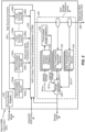
- Processing system 101 is generally configured for bandwidth throttling based on danger signals monitored from one or more hardware elements, such as cores 222, which may utilize shared resources, like memory 112, interconnect 210, etc.
- Processing system 101 may comprise a quality of service (“QoS") controller 204 that is coupled to one or more unacceptable deadline miss (UDM) cores generally designated with the reference numeral 222a, comprising UDM cores 222a1 and 222a2.
- QoS quality of service
- UDM unacceptable deadline miss
- UDM cores 222a1-a2 may cause exemplary error conditions such as, but not limited to, display underflows, camera overflows, dropped telephone calls, sluggish Internet connections, etc. which are considered to be unacceptable in this disclosure.
- UDM cores 222a1-a2 may comprise a danger level sensor "A" which produces a danger level signal "B,” where danger level signal B is received and monitored by QoS controller 204.
- Non-UDM cores 222b1-b4 are not shown to include danger level sensors A.
- processing system 101 also includes hybrid UDM cores (HUCs) generally designated by the reference numeral 222c and comprising HUCs 222c1 and 222c2.
- HUCs 222c1-c2 also include danger level sensors, which are designated as hybrid danger level sensors H.
- Hybrid danger level sensors H are also configured to generate danger level signal B received and monitored by QoS controller 204.
- HUCs 222c also generate priority mode signals F, received and monitored by QoS controller 204, and receive intra-HUC QoS policy signals G from QoS controller 204. Signals F, G, and H related to HUCs 222c are explained in further detail with reference to FIG. 2 below.
- Each UDM-core 222a, non-UDM core 222b, and HUC 222c may be coupled to a traffic shaper or traffic throttle, generally designated with the reference numeral 206 and comprising traffic throttles 206a-j coupled to respective cores 222.
- Traffic throttle 206 may be coupled to interconnect 210, which can comprise one or more switch fabrics, rings, crossbars, buses etc. as understood by one of ordinary skill in the art.
- Interconnect 210 may be coupled to one or more memory controllers 214.
- Memory controllers generally designated by the reference numeral 214 and comprising memory controllers 214a-n, may be coupled to memory 112.
- Memory 112 may comprise volatile or non-volatile memory.
- Memory 112 may include, but is not limited to, DRAM, IMEM, etc.
- processing system 101 may also include PCI controller coupled to one or more PCI peripherals through a PCI-e external transport.
- QoS controller 204 may issue command signals to individual traffic throttles 206 via throttle level command line 208. Similarly, QoS controller 204 may issue memory controller QoS Policy signals to individual memory controllers 214 via memory controller QoS Policy data line 212. QoS controller 204 may also issue commands 220A to change frequency of interconnect and/or memory controllers to frequency controller 202. QoS controller 204 may monitor the danger level signals B generated by UDM cores 222a and HUCs 222c. QoS controller 204 may also monitor interconnect and memory controller frequencies designated as input 218.
- Frequency controller 202 may issue frequency change commands to interconnect 210 and memory controllers 214, respectively via command lines 220B and 220C.
- Frequency controller 202 may receive, as inputs, frequency change requests 216 from masters, such as from UDM cores 222a, non-UDM cores 222b, and HUCs 222c.
- masters such as from UDM cores 222a, non-UDM cores 222b, and HUCs 222c.
- frequency controller 202 may also receive commands 220A to change frequency for the interconnect 210 and or memory controllers 214 from QoS controller 204.
- QoS controller 204 receives danger level signals B from UDM cores 222a and HUCs 222c. In addition, QoS controller 204 also receives priority mode signal F from HUCs 222c. Danger level signals B will first be explained to illustrate operation of QoS controller 204. However, a detailed explanation of QoS controller 204, frequency controller 202, and related aspects will be avoided in this disclosure, except as it pertains to HUCs 222c. Applicant's co-pending U.S. Patent Applications, with serial numbers 14/588,798 and 14/588,812 provide a detailed explanation of processing system 101 for non-HUCs including UDM cores 222a and non-UDM cores 222b.
- Danger level signals B may comprise information indicating levels or degrees at which a UDM core 222a believes that it is in danger of not meeting a deadline and/or it is in danger of a failure.
- the failure may comprise one or more error conditions described above in the background section for hardware devices such as, but not limited to, a display engine, a camera, and a modem.
- Each danger level signal B may be unique relative to a respective hardware element.
- QoS controller 204 determines an appropriate QoS policy for each core 222 (comprising UDM cores 222a, non-UDM cores 222b, and HUCs 222c) being monitored. It will be understood that in aspects of this disclosure, some cores 222 may not explicitly signal or assert a danger level signal B, but as discussed herein, QoS controller 204 may also treat the lack of receiving a danger level signal B from one or more cores 222 as information indicating degree of danger of the one or more cores 222 which did not signal a danger level, e.g., that those one or more cores 222 are not in danger.
- detecting or determining danger levels B not only includes an explicitly asserted danger level signal, but also encompasses cases where a danger level signal B is not explicitly asserted.
- QoS controller 204 maintains individual QoS policies for each core 222.
- the application of the QoS policy for each core 222 being monitored is conveyed or relayed via the throttle level command line 208 to each respective throttle 206 which is assigned to a particular core 222.
- Each traffic throttle 206 adjusts bandwidth from a respective core 222 to match the bandwidth level "D" specified by QoS controller 204 via the throttle level command line 208.
- the QOS policy conveyed to traffic throttles 206 may also instruct traffic throttles 206 to change the priority of transactions flowing through them to a lower level, such that transactions from UDM cores 222a or HUC cores 222c are given higher priority at downstream shared resources like interconnect 210, memory 112, etc.
- QoS controller 204 may throttle or alter the priority of the traffic or bandwidth of aggressor cores of cores 222, which may or may not be UDM type hardware elements, keeping in mind that the policy for throttling HUCs 222c is different, and will be based on priority mode signal F, in addition to danger level signal B from the HUCs 222c.
- UDM cores 222a may receive more bandwidth and/or lower latency transactions from the processing system 101 thereby reducing respective danger levels of respective UDM cores 222a.
- QoS controller 204 may also determine an appropriate operating frequency "E" for each memory controller 214 as well as for interconnect 210. By increasing the frequency of interconnect 210 and/or one or more memory controllers 214, UDM cores 222a, for example, may receive more operating bandwidth. QoS controller 204 may decrease frequency once it determines that one or more UDM cores 222a are not in danger of failure. Specifically, QoS controller 204 may issue frequency control commands to frequency controller 202 via a frequency command line 220A. Frequency controller 202 may in turn issue frequency change commands on the lines 220B, 220C to interconnect 210 and memory controllers 214.
- a first consideration relates to external throttling.
- External throttling applies in cases, where, for example, one or more non-HUC UDM cores 222a (e.g., a display engine, as previously mentioned) sense danger and raise danger level signals B, based on which, QoS controller 204 may seek to throttle all bandwidth aggressors, including HUCs 222c.
- non-HUC UDM cores 222a e.g., a display engine, as previously mentioned
- QoS controller 204 may seek to throttle all bandwidth aggressors, including HUCs 222c.
- HUCs 222c may include active UDM and non-UDM threads, where, again the non-UDM threads may themselves be aggressors, the UDM thread as well as the non-UDM aggressor threads of HUCs 222c1-c2 may end up getting throttled. While it is desirable to throttle the non-UDM threads, UDM threads should not be throttled in the course of preventing unacceptable failures from occurring. Therefore, HUCs 222c are designed to throttle the non-UDM threads/cores within the HUCs 222c, without affecting the UDM threads/cores in the following manner.
- a second consideration pertains to internal pressures arising from a HUC, for example, when a HUC's UDM thread is in danger of missing a deadline due to resource contention from aggressor non-UDM threads running on the same HUC.
- the aggressor non-UDM threads may put the UDM thread in danger of unacceptable failure by hogging shared resources.
- the shared resources may be inside the HUC, e.g., cache, buffers, outstanding transactions, etc.
- the shared resources may also be outside the HUC, e.g., bandwidths of interconnect 210 or memory 112.
- HUC 222c1 for example, experiences internal pressures
- QoS controller 204 cannot apply throttling via throttle 206f for HUC 222c1, since there is no spatial separation of the UDM and non-UDM threads running concurrently on HUC 222c1.
- UDM threads are provided with added resiliency to meet their deadline in the presence of aggressor non-UDM threads, in exemplary aspects.
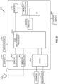
- HUC 222c is shown to comprise two or more multithreaded programmable cores designated as 324a-n.
- Multithreaded programmable cores 324a-n may be configured as a CPU/DSP/GPU, etc., and can have one or more programmable threads, wherein each thread can be a UDM thread or a non-UDM thread.
- HUC 222c also includes fixed function sub-cores 326a-n, which can comprise UDM sub-cores and/or non-UDM sub-cores. While multithreaded programmable cores 324a-n have threads which are programmable, the fixed function sub-cores 326a-n are sub-cores designed to implement fixed functions.
- Priority mode register 320 comprises information regarding a mix of UDM and non-UDM threads/cores. In general, a higher priority may be applicable to a HUC which has a higher composition of UDM threads/cores and a lower priority may be applicable to a HUC with a lower composition of UDM threads/cores.
- Priority mode F is a signal which is output from priority mode register 320, and provided to QoS controller 204 as shown in FIG. 1 . In addition to danger level signal B, QoS controller 204 receives priority mode signal F from HUCs 222c. Priority mode signal F enables QoS controller 204 to evaluate the extent to which HUCs 222c may be throttled.
- HUC 222c2 has a large number of UDM threads (indicated, for example, by a higher value of priority mode signal F)
- QoS controller 204 may not apply any throttling to corresponding throttle 206j.
- QoS scheduler 204 may treat HUC 222c1 as a non-UDM core for purposes of throttling and apply larger throttling on throttle 206f.
- the priority mode signal F may be used by QoS controller 204 as an index to a table that comprises the QoS policy (which governs throttling and/or priority levels) that QoS controller 204 is allowed to apply to the throttle (e.g., throttle 206j) that is coupled to the particular HUC 222c (e.g., HUC 222c2).
- the throttle e.g., throttle 206j
- HUC 222c e.g., HUC 222c2
- threads/cores may be UDM or non-UDM based on the tasks running on them.
- a programmable thread may be UDM for some tasks and non-UDM for some other tasks, and therefore, the composition of active UDM threads/cores in a HUC can vary in a dynamic manner.
- Multithreaded programmable cores 324a-n and fixed function sub-cores 326a-n output data on respective read and write transaction buses 304a-n and 306a-n.
- Read and write transaction buses 304a-n and 306a-n are coupled to the HUC's output transaction scheduler/multiplexor (OTSM) 300, which is explained further with reference to FIG. 3 .
- OTSM output transaction scheduler/multiplexor
- OTSM 300 is configured to receive the various transactions from read and write transaction buses 304a-n and 306a-n, and based on particular danger levels (internal and external), throttle non-UDM threads/cores as necessary, consider various priority levels assigned to the transactions, and prioritize and schedule the transactions to be sent out to interconnect 210, for example, through read and write transactions to interconnect bus 338. Some transactions (e.g., of non-UDM threads/cores) may be stalled or killed by OTSM 300.
- the signal stall source command 305 is an output from OTSM 300, which is used to stall any one or more of non-UDM threads/sub-cores of multithreaded programmable cores 324a-n or fixed function sub-cores 326a-n. Stall source command 305 can be temporarily applied to particular threads/cores of multithreaded programmable cores 324a-n and fixed function sub-cores 326a-n,
- Intra-HUC QoS policy signal G is an output of QoS controller 204, which is input to HUC 222c, and specifically, an input to OTSM 300. Intra-HUC QoS policy signal G conveys an external danger to HUC 222c.
- QoS controller 204 may receive danger level signals B from one or more UDM cores 222a and/or other HUCs 222c (e.g., HUC 222c1) to determine how much throttling may be applied to non-UDM cores/threads of a particular HUC 222c (e.g., HUC 222c2), once again, keeping in mind that an explicit signal may not be received in some cases to indicate corresponding danger level of a core 222 (e.g., one or more UDM cores 222a and/or one or more HUCs 222c may indicate lack of danger by not asserting an explicit danger level signal).
- HUC 222c HUC 222c
- danger level signal B Another input to OTSM 300 is danger level signal B which is also an output of HUC 222c supplied to QoS controller 204.
- Danger level signal B is generated within HUC 222c by HUC danger level detection sensor H, designated as block 340 in FIG. 2 .
- HUC danger level detection block 340 can involve various types of danger level detection and includes danger aggregator 336 to provide an aggregated danger level signal B based on the various types of danger levels that can be detected.
- danger level signal 301a can be an internal danger signal generated by HUC 222c, which can be provided directly from software writable registers 328 (which may be dynamically programmed or statically set for each thread/core, to indicate that if a UDM thread/core is pending transmission, then danger must be triggered).
- timer-based danger detection block 330 may be used, where software writable registers 328 can set a timer, and if a UDM thread does not disable the timer of HUC 222c prior to the timer expiring, then at the expiry of the timer, for example, danger signal 301b can be set.
- Hardware based danger triggers can also be provided by per thread/core bandwidth monitor 332 and per thread/core external latency monitor 334.
- Danger signals 301c can be generated by per thread/core bandwidth monitor 332 if bandwidth available for a UDM thread drops below a certain threshold specific to the thread, for example.
- Danger signals 301d can be generated by per thread/core external latency monitor 334 if, for example the latency of a transaction for a UDM thread (e.g., time taken for read data to be returned to a UDM thread/core after the corresponding read command is sent out on read and write transaction bus 338) exceeds a predetermined threshold.
- Danger level aggregator 336 may aggregate danger signals 301a-d in any suitable manner, for example, a weighted sum, or by implementing a lookup table, or other aggregation/combination mechanism. Danger level signal B output by danger aggregator 336 is provided to both QoS controller 204, as well as OTSM 300, as previously explained. As previously discussed, not all of danger signals 301a-d may be asserted or have an explicit value in some cases, and danger aggregator 336 may take into account lack of assertion of a specific danger signal also into consideration in determining danger levels.
- each UDM thread/core may detect (e.g., through hardware, software, or a combination thereof) that the UDM thread/core is in danger and conveys corresponding danger level signal B to QoS controller 204 (external to HUC 222c) and to OTSM 300 (internal to HUC 222c) as above.
- QoS controller 204 receives and monitors danger level signals B from the various cores 222 of processing system 101
- OTSM 300 which is internal to HUC 222c, manages danger internally so as to protect UDM threads/cores from unacceptable failures.
- OTSM 300 is configured to throttle non-UDM threads/cores from multithreaded programmable cores 324a-n and fixed function sub-cores 326a-n as necessary, to ensure that UDM threads/cores are not in danger.
- OTSM 300 includes traffic scheduler and multiplexors 405, which receives transactions from multithreaded programmable cores 324a-n and fixed function sub-cores 326a-n on respective read and write transaction buses 304a-n and 306a-n. Read and write transactions may also be merged into a single read-write bus as known in the art.
- traffic scheduler and multiplexors 405 can forward a first subset, shown as transactions 304x/306x to transaction scoreboard 404.
- a second subset of the transactions received from read and write transaction buses 304a-n and 306a-n shown as transactions 304y/306y, can bypass transaction scoreboard 404 and be sent directly to output transactions arbiter 407.
- the second subset comprising transactions 304y/306y can include, for example, write transactions in some aspects.
- write transactions may not affect consumption of shared resources in the same way that read transactions will (e.g., in the aforementioned example of a UDM thread/core processing an audio application, shared DRAM bandwidth may be hogged by a non-UDM aggressor thread/core, causing the UDM thread/core to be starved or throttled, leading to an unacceptable audible pop if the read data from the shared DRAM is not received by the audio UDM thread/core in time; a similar problem may not exist in the case of write transactions however).
- Transaction scoreboard 404 implements a two-step process with regard to the first subset of transactions 304x/306x.
- transaction scoreboard 404 is designed to delay transmission of transactions from non-UDM threads of the first subset of transactions 304x/306x.
- transaction scoreboard 404 is configured to group transactions from threads/cores into multiple groups of decreasing priority, such that, in the presence of danger, more delay is applied to lower priority non-UDM threads/cores.
- Grouping the transactions in this manner allows for slowing down the execution of the non-UDM threads/cores by causing the amount of shared resources (internal and external to HUC 222c) consumed by the non-UDM threads/cores to be reduced.
- the danger levels internal and/or external to HUC 222c
- the amount of delay applied to each transaction from non-UDM threads increase.
- transaction scoreboard 404 is seen to comprise multiple entries with indices "1-k.” Each entry can have a transaction or group of transactions in one field, and an associated priority indicated as "transaction source priority" in another field. Some entries of transaction scoreboard 404 may not have any transactions, and so they are shown as an "empty slot.” The order of transactions in transaction scoreboard 404 is not indicative of their priority, and as such, the priority of each transaction is stored in the transaction source priority field. The organization of transaction scoreboard 404 in this manner allows insertion and deletion of transactions from transaction scoreboard 404 in any order and not necessarily in order or arrival.
- highest priority transactions will be UDM threads/cores while non-UDM threads/cores receive lower/lowest priority values in transaction scoreboard 404. It will be understood that while certain transactions may have predetermined priority levels, it is also possible for priority levels of transactions in transaction scoreboard 404 to change over time. For example, a thread/core which pertains to a prefetch operation (i.e., for fetching data from a shared resource such as memory 112, prior to an actual demand for the data) might be low.
- OTSM 300 also includes N counters depicted with reference numerals 403a-n, which respectively count how many transactions there are in transaction scoreboard 404 with priority levels ranging from 1-N. For example, priority 1 transaction counter 403a counts the number of transactions with the highest priority level "1.” Similarly, priority N transaction counter 403n counts the number of transactions with the lowest priority level "N”.
- QoS policy generator 401 is a module which accepts danger level signal B (internal danger) from HUC danger detection sensor H (of FIG. 2 ) and intra-HUC QoS policy signal G (external danger) and supplies a consolidated danger level on the signal shown as scoreboard QoS policy 410, to scoreboard dequeue scheduler 402.
- QoS policy generator 401 may be implemented as a lookup table which is indexed by danger level signal B and intra-HUC QoS policy signal G, and the indexed entry may comprise the consolidated danger level, provided as an output from QOS policy generator 401 as scoreboard QoS policy 410.
- QoS policy generator 401 may be implemented as a fixed or programmable logical function or even as a programmable core, such as a micro-controller.
- QOS policy generator 401 can be a register that is regularly programmed by one of the threads/cores of HUC 222c.
- scoreboard dequeue scheduler 402 receives the counts of the number of transactions of the various priority levels from counters 403a-n and the consolidated danger level, scoreboard QoS policy 410, from QoS policy generator 401. Scoreboard dequeue scheduler 402 thus has information on how many transactions/transaction groups are currently pending in transaction scoreboard 404 with the various associated priority levels, as well as the consolidated indication of internal and external danger. Scoreboard dequeue scheduler 402 uses this information to determine which transactions should be dequeued and sent out to output transactions arbiter 407 through scoreboard dequeue engine 306.
- the consolidated internal and external danger indication on scoreboard QoS policy 410 is low, then more of low priority (e.g., non-UDM threads/cores) can be dequeued through scoreboard dequeue engine 306. If the consolidated internal and external danger indication on scoreboard QoS policy 410 is high, then low priority (e.g., non-UDM threads/cores) will be delayed while high priority (e.g., UDM threads) will be allowed to be dequeued through scoreboard dequeue engine 306.
- low priority e.g., non-UDM threads/cores
- high priority e.g., UDM threads
- one or more low priority transactions may be scheduled if the determined danger levels for the two or more threads is low, and one or more high priority transactions may be scheduled while scheduling of of one or more low priority transactions is delayed, if the determined danger levels of the two or more threads is high.
- scoreboard dequeue scheduler 402 may employ arbitration schemes to select one transaction from the group of transactions, where the arbitration schemes can involve round-robin, first-come-first-serve, random selection, or other techniques known in the art.
- Output transactions arbiter 407 receives and arbitrates between the transactions to be dequeued from transaction scoreboard 404 through scoreboard dequeue engine 306 and the second subset of transactions 304y/306y which bypass transaction scoreboard 404.
- Output transactions arbiter 407 sends out read and write transactions to interconnect 338 (e.g., to shared interconnect 210 from FIG. 1 ) based on the arbitration. For example, if high priority transactions from UDM threads/cores are received from scoreboard dequeue engine 306, output transactions arbiter 407 prioritizes the transactions to be dequeued from transaction scoreboard 404 over the second subset of transactions 304y/306y which bypass transaction scoreboard 404.
- the first step of the aforementioned two-step process implemented by OTSM 300 to schedule transactions is considered to be completed when transactions are sent out by output transactions arbiter 407 to the bus designated as read and write transactions to interconnect 338.
- Scoreboard dequeue scheduler 402 is once again employed. Scoreboard dequeue scheduler 402 is configured to determine if a predetermined number of low priority transactions (e.g., from non-UDM threads/cores) is exceeded, based on the information supplied by counters 403a-n. If the number of transactions in transaction scoreboard 404 from non-UDM threads exceeds the predetermined number, then the execution of these non-UDM threads which are filling up transaction scoreboard 404 with these large numbers of low priority transactions will be stalled. This is particularly the case when the consolidated internal and external danger level indication on scoreboard QoS policy 410 is high.
- a predetermined number of low priority transactions e.g., from non-UDM threads/cores
- Scoreboard dequeue scheduler 402 generates the aforementioned stall source command 305 (see discussion of FIG. 2 ) to temporarily stall execution of one or more non-UDM threads on multithreaded programmable cores 324a-n and/or fixed function core 326a-n, until the number of transactions from these low priority threads in transaction scoreboard 404 decreases. As will be recognized, by this process, lower priority non-UDM thread groups are stalled prior to higher priority non-UDM thread groups.
- HUC 222c comprising UDM threads/cores (also known as real time threads/cores) as well as non-UDM threads/cores (also known as non-real time threads/cores) can enforce a quality of service (QoS) among the threads/cores and schedule/manage the various threads/cores in such a manner that UDM threads/cores are prevented from being throttled or caused to fail in an unacceptable manner.
- QoS quality of service
- HUC 222c can implement hardware-based solutions for detection and signaling of danger to UDM threads/cores (e.g., as shown and described with reference to FIGS.
- the level of QoS restraint or throttling applied to each thread is a function of the danger level to the thread and the priority of the thread.
- FIG. 4 illustrates a method 500 of managing shared resources in a multithreaded processor (e.g., HUC 222c) comprising two or more processing threads (e.g., UDM threads/cores and non-UDM threads/cores of multithreaded programmable cores 324a-n, fixed function cores 326a-n, etc.).
- the multithreaded processor can be one of a digital signal processor (DSP), general purpose processor (GPP), or a central processing unit (CPU), for example.
- DSP digital signal processor
- GPS general purpose processor
- CPU central processing unit
- method 500 includes determining danger levels for the two or more threads, wherein the danger level of a thread is based on a potential failure of the thread to meet a deadline due to unavailability of a shared resource.
- danger aggregator 336 supplies internal danger level of HUC 222c on danger level signal B and external danger level is supplied through intra-HUC QoS policy signal G to OTSM 300.
- Danger levels for threads are based on likelihood that a thread will be throttled/starved of a shared resource such as interconnect 210, memory 112, etc.
- method 500 includes detecting priority levels associated with the two or more threads, wherein the priority level is higher for a thread whose failure to meet a deadline is unacceptable and the priority level is lower for a thread whose failure to meet a deadline is acceptable.
- grouping transactions from the one or more threads in a scoreboard e.g., transaction scoreboard 404 based on priority levels of the threads allows the scheduling based on priority levels.
- transaction scoreboard 404 stores priority levels for various transactions, grouped in order of priority levels.
- Counters 403a-n count the number of transactions with each priority level and supply them to scoreboard dequeue scheduler 402.
- method 500 includes scheduling the two or more threads based at least on the determined danger levels for the two or more threads and priority levels associated with the two or more threads. For example, consolidated internal and external danger levels are provided on the signal scoreboard QoS policy 410 to scoreboard dequeue scheduler 402. Combined with the priority level information from counters 403a-n, scoreboard dequeue scheduler 402 instructs scoreboard dequeue engine 306 to dequeue and schedule the pending transactions in transaction scoreboard 404. The transactions are sent out to interconnect 210, for example, by output transactions arbiter 407.
- At least one low priority thread e.g., non-UDM core/thread
- a low priority thread/core is prevented from being scheduled by scoreboard dequeue scheduler 402, or a thread/core generating a low priority transaction is prevented/stalled from execution by stall source command 305 supplied by scoreboard dequeue scheduler 402
- throttling the low priority thread can mean preventing or delaying scheduling of a low priority transaction from the low priority thread, where the low priority transaction will consume shared resources if scheduled.
- throttling the low priority thread can also lead to or enable scheduling a high priority transaction from at least one high priority thread (e.g., a UDM thread/core) whose failure to meet a deadline is unacceptable, wherein shared resources for the high priority thread are made available based on throttling the low priority transaction (e.g., interconnect 210/memory 112 may be used for transactions from the UDM threads/cores which are scheduled by throttling the non-UDM threads/cores).
- a high priority thread e.g., a UDM thread/core
- shared resources for the high priority thread are made available based on throttling the low priority transaction
- interconnect 210/memory 112 may be used for transactions from the UDM threads/cores which are scheduled by throttling the non-UDM threads/cores.
- determining the danger levels for the two or more threads is based on an internal danger level of the two or more threads (e.g., danger level signal B provided by danger aggregator 336) and an external danger level of one or more cores of a system comprising the multithreaded processor (e.g., intra-HUC QoS policy signal G supplied by QoS controller 204), while keeping in mind that one or more internal danger levels or external danger levels may not be explicitly asserted.
- an internal danger level of the two or more threads e.g., danger level signal B provided by danger aggregator 336) and an external danger level of one or more cores of a system comprising the multithreaded processor (e.g., intra-HUC QoS policy signal G supplied by QoS controller 204), while keeping in mind that one or more internal danger levels or external danger levels may not be explicitly asserted.
- the internal danger level can be based (e.g., from danger aggregator 336) on one or more of a danger level (e.g., 301a) provided by a software programmable register (e.g., 328) programmed with danger levels for each thread, a danger level (E.g., 301b) provided by a timer (e.g., 330) if the timer expires before a task associated with a thread is completed, a danger level (e.g., 301c) provided by a bandwidth monitor for each thread (e.g., 332), or a danger level (e.g., 301d) provided by a latency monitor for each thread (e.g., 334).
- a danger level e.g., 301a
- a software programmable register e.g., 328
- a danger level E.g., 301b
- a timer e.g., 330
- a danger level e.g.,
- Wireless device or PCD 600 includes certain aspects of processing system 101 of FIG. 1 , as will be explained below.
- HUC 222c can be configured as a multithreaded processor comprising a mix of UDM threads/cores and non-UDM threads/cores as shown in FIGS. 2-3 .
- HUC 222c can be a DSP, a CPU, a general purpose processor, etc.
- HUC 222c can be configured to perform the method 500 of FIG. 4 .
- FIG. 5 such as throttle 206f/206j coupled to HUC 222c and to interconnect 210 and memory controllers 214 coupled to interconnect 210 and to memory 112 are representatively shown in FIG. 5 , while other aspects of FIG. 1 such as QoS controller 204, frequency controller 202, and related interconnections, have not been shown in FIG. 5 , for the sake of clarity, while keeping in mind that the various aspects and details of FIG. 1 , although not explicitly shown again in FIG. 5 , may be included in wireless device 600. As shown in FIG.
- HUC 222c may also be directly coupled to memory 112 for some applications (while in exemplary aspects, communication between HUC 222c and memory 112 may be through components such as throttle 206f/206j, interconnect 210, memory controllers 214, etc., configured between HUC 222c and memory 112).
- FIG. 5 also shows display controller 626 that is coupled to HUC 222c and to display 628.
- Coder/decoder (CODEC) 634 e.g., an audio and/or voice CODEC
- CDEC Coder/decoder
- Other components such as wireless controller 640 (which may include a modem) are also illustrated.
- Speaker 636 and microphone 638 can be coupled to CODEC 634.
- FIG. 5 also indicates that wireless controller 640 can be coupled to wireless antenna 642.
- HUC 222c, display controller 626, memory 112, CODEC 634, and wireless controller 640 (and in some examples, aspects of FIG.
- processing system 101 such as QoS controller 204, frequency controller 202, various throttles 206, various memory controller 214, interconnect 210, etc.
- QoS controller 204 may be included in processing system 101, which can be configured as a system-in-package or system-on-chip device.
- display controller 626, wireless controller 640, and CODEC 634 can comprise one or more of cores 222 shown in FIG. 1 (e.g., UDM cores 222a, non-UDM cores 222b, etc.).
- input device 630 and power supply 644 are coupled to the system-on-chip device or processing system 101.
- display 628, input device 630, speaker 636, microphone 638, wireless antenna 642, and power supply 644 are external to the system-on-chip device or processing system 101.
- each of display 628, input device 630, speaker 636, microphone 638, wireless antenna 642, and power supply 644 can be coupled to a component of the system-on-chip device or processing system 101, such as an interface or a controller.
- FIG. 5 depicts a wireless communications device
- HUC 222c and memory 112 may also be integrated into a set-top box, a music player, a video player, an entertainment unit, a navigation device, a personal digital assistant (PDA), a fixed location data unit, a computer, a laptop, a tablet, a mobile phone, or other similar devices.
- PDA personal digital assistant
- a software module may reside in RAM memory, flash memory, ROM memory, EPROM memory, EEPROM memory, registers, hard disk, a removable disk, a CD-ROM, or any other form of storage medium known in the art.
- An exemplary storage medium is coupled to the processor such that the processor can read information from, and write information to, the storage medium. In the alternative, the storage medium may be integral to the processor.
- an aspect of the invention can include a computer readable media embodying a method for managing/scheduling threads of a multithreaded processor. Accordingly, the invention is not limited to illustrated examples and any means for performing the functionality described herein are included in aspects of the invention.
Landscapes
- Engineering & Computer Science (AREA)
- Theoretical Computer Science (AREA)
- Software Systems (AREA)
- Physics & Mathematics (AREA)
- General Engineering & Computer Science (AREA)
- General Physics & Mathematics (AREA)
- Quality & Reliability (AREA)
- Health & Medical Sciences (AREA)
- Biomedical Technology (AREA)
- Debugging And Monitoring (AREA)
- Hardware Redundancy (AREA)
- Multi Processors (AREA)
Applications Claiming Priority (3)
| Application Number | Priority Date | Filing Date | Title |
|---|---|---|---|
| US201562168708P | 2015-05-29 | 2015-05-29 | |
| US14/866,012 US10102031B2 (en) | 2015-05-29 | 2015-09-25 | Bandwidth/resource management for multithreaded processors |
| PCT/US2016/029530 WO2016195851A1 (en) | 2015-05-29 | 2016-04-27 | Bandwidth/resource management for multithreaded processors |
Publications (2)
| Publication Number | Publication Date |
|---|---|
| EP3304301A1 EP3304301A1 (en) | 2018-04-11 |
| EP3304301B1 true EP3304301B1 (en) | 2023-04-26 |
Family
ID=57398627
Family Applications (1)
| Application Number | Title | Priority Date | Filing Date |
|---|---|---|---|
| EP16722472.4A Active EP3304301B1 (en) | 2015-05-29 | 2016-04-27 | Bandwidth/resource management for multithreaded processors |
Country Status (8)
| Country | Link |
|---|---|
| US (1) | US10102031B2 (zh) |
| EP (1) | EP3304301B1 (zh) |
| JP (1) | JP6703009B2 (zh) |
| KR (1) | KR102560556B1 (zh) |
| CN (1) | CN107646104B (zh) |
| CA (1) | CA2983800A1 (zh) |
| TW (1) | TWI711932B (zh) |
| WO (1) | WO2016195851A1 (zh) |
Families Citing this family (14)
| Publication number | Priority date | Publication date | Assignee | Title |
|---|---|---|---|---|
| US9864647B2 (en) | 2014-10-23 | 2018-01-09 | Qualcom Incorporated | System and method for dynamic bandwidth throttling based on danger signals monitored from one more elements utilizing shared resources |
| US20160127259A1 (en) * | 2014-10-31 | 2016-05-05 | Qualcomm Incorporated | System and method for managing safe downtime of shared resources within a pcd |
| US10067691B1 (en) * | 2017-03-02 | 2018-09-04 | Qualcomm Incorporated | System and method for dynamic control of shared memory management resources |
| TWI639955B (zh) * | 2017-11-06 | 2018-11-01 | 晨星半導體股份有限公司 | 多處理器系統及其處理器管理方法 |
| CN108845870B (zh) * | 2018-05-29 | 2021-05-07 | 大连理工大学 | 一种基于pWCET整形的概率性实时任务调度方法 |
| CN110737616B (zh) * | 2018-07-20 | 2021-03-16 | 瑞昱半导体股份有限公司 | 处理中断优先级的电路系统 |
| US10929139B2 (en) * | 2018-09-27 | 2021-02-23 | Qualcomm Incorporated | Providing predictive instruction dispatch throttling to prevent resource overflows in out-of-order processor (OOP)-based devices |
| TWI684131B (zh) * | 2019-02-26 | 2020-02-01 | 華碩電腦股份有限公司 | 資料傳輸裝置、資料傳輸方法以及非暫態電腦可讀取記錄媒體 |
| US11340948B2 (en) * | 2019-05-30 | 2022-05-24 | Microsoft Technology Licensing, Llc | Timed multi-thread access for high-throughput slow-response systems |
| CN111078394B (zh) * | 2019-11-08 | 2022-12-06 | 苏州浪潮智能科技有限公司 | 一种gpu线程负载均衡方法与装置 |
| JP7002618B1 (ja) * | 2020-10-08 | 2022-01-20 | レノボ・シンガポール・プライベート・リミテッド | 電子機器、及び制御方法 |
| KR20220048619A (ko) * | 2020-10-13 | 2022-04-20 | 에스케이하이닉스 주식회사 | 메모리 시스템, 메모리 콘트롤러 및 메모리 콘트롤러의 동작 방법 |
| US11770647B2 (en) * | 2021-02-02 | 2023-09-26 | Mediatek Inc. | Task assigning method and task assigning device |
| WO2023167438A1 (ko) * | 2022-03-03 | 2023-09-07 | 삼성전자주식회사 | 시스템의 성능 병목 현상을 처리하는 전자 장치 및 그 동작 방법 |
Family Cites Families (26)
| Publication number | Priority date | Publication date | Assignee | Title |
|---|---|---|---|---|
| US6499072B1 (en) * | 1999-09-02 | 2002-12-24 | Ati International Srl | Data bus bandwidth allocation apparatus and method |
| US7096471B2 (en) * | 2001-06-01 | 2006-08-22 | Texas Instruments Incorporated | Apparatus for resource management in a real-time embedded system |
| US7689998B1 (en) * | 2004-07-13 | 2010-03-30 | Microsoft Corporation | Systems and methods that manage processing resources |
| US8091088B2 (en) * | 2005-02-22 | 2012-01-03 | Microsoft Corporation | Method and system for hierarchical resource management involving hard and soft resource limits |
| US8245230B2 (en) * | 2005-03-14 | 2012-08-14 | Qnx Software Systems Limited | Adaptive partitioning scheduler for multiprocessing system |
| JP2006343872A (ja) * | 2005-06-07 | 2006-12-21 | Keio Gijuku | マルチスレッド中央演算装置および同時マルチスレッディング制御方法 |
| GB2443277B (en) | 2006-10-24 | 2011-05-18 | Advanced Risc Mach Ltd | Performing diagnostics operations upon an asymmetric multiprocessor apparatus |
| US8028286B2 (en) * | 2006-11-30 | 2011-09-27 | Oracle America, Inc. | Methods and apparatus for scheduling threads on multicore processors under fair distribution of cache and other shared resources of the processors |
| GB2449455B (en) * | 2007-05-22 | 2011-08-03 | Advanced Risc Mach Ltd | A data processing apparatus and method for managing multiple program threads executed by processing circuitry |
| US8151008B2 (en) | 2008-07-02 | 2012-04-03 | Cradle Ip, Llc | Method and system for performing DMA in a multi-core system-on-chip using deadline-based scheduling |
| EP2192492B1 (en) * | 2008-11-24 | 2012-11-14 | Barcelona Supercomputing Center-Centro Nacional de Supercomputación | Method, mechanism and computer program product for executing several tasks in a multithreaded processor and for providing estimates for worst-case execution times |
| US9588715B2 (en) * | 2009-06-03 | 2017-03-07 | Hewlett-Packard Development Company, L.P. | Scheduling realtime information storage system access requests |
| GB2473505B (en) * | 2009-09-15 | 2016-09-14 | Advanced Risc Mach Ltd | A data processing apparatus and a method for setting priority levels for transactions |
| US9106591B2 (en) * | 2009-12-24 | 2015-08-11 | Delphix Corporation | Adaptive resource management using survival minimum resources for low priority consumers |
| US8370665B2 (en) * | 2010-01-11 | 2013-02-05 | Qualcomm Incorporated | System and method of sampling data within a central processing unit |
| US9026748B2 (en) | 2011-01-11 | 2015-05-05 | Hewlett-Packard Development Company, L.P. | Concurrent request scheduling |
| US20120210150A1 (en) * | 2011-02-10 | 2012-08-16 | Alcatel-Lucent Usa Inc. | Method And Apparatus Of Smart Power Management For Mobile Communication Terminals |
| US20130007755A1 (en) * | 2011-06-29 | 2013-01-03 | International Business Machines Corporation | Methods, computer systems, and physical computer storage media for managing resources of a storage server |
| US20130074088A1 (en) * | 2011-09-19 | 2013-03-21 | Timothy John Purcell | Scheduling and management of compute tasks with different execution priority levels |
| US8935699B1 (en) | 2011-10-28 | 2015-01-13 | Amazon Technologies, Inc. | CPU sharing techniques |
| US9021493B2 (en) * | 2012-09-14 | 2015-04-28 | International Business Machines Corporation | Management of resources within a computing environment |
| US9632822B2 (en) * | 2012-09-21 | 2017-04-25 | Htc Corporation | Multi-core device and multi-thread scheduling method thereof |
| US9063795B2 (en) * | 2012-12-19 | 2015-06-23 | International Business Machines Corporation | Adaptive resource usage limits for workload management |
| US9135062B2 (en) | 2013-04-09 | 2015-09-15 | National Instruments Corporation | Hardware assisted method and system for scheduling time critical tasks |
| JP2015064861A (ja) * | 2013-08-29 | 2015-04-09 | 株式会社デンソー | マルチスレッドプロセッサ |
| US9864647B2 (en) * | 2014-10-23 | 2018-01-09 | Qualcom Incorporated | System and method for dynamic bandwidth throttling based on danger signals monitored from one more elements utilizing shared resources |
-
2015
- 2015-09-25 US US14/866,012 patent/US10102031B2/en active Active
-
2016
- 2016-04-27 CN CN201680029327.9A patent/CN107646104B/zh active Active
- 2016-04-27 EP EP16722472.4A patent/EP3304301B1/en active Active
- 2016-04-27 WO PCT/US2016/029530 patent/WO2016195851A1/en active Search and Examination
- 2016-04-27 KR KR1020177034177A patent/KR102560556B1/ko active IP Right Grant
- 2016-04-27 CA CA2983800A patent/CA2983800A1/en not_active Abandoned
- 2016-04-27 JP JP2017561312A patent/JP6703009B2/ja active Active
- 2016-05-20 TW TW105115830A patent/TWI711932B/zh active
Also Published As
| Publication number | Publication date |
|---|---|
| US20160350152A1 (en) | 2016-12-01 |
| CA2983800A1 (en) | 2016-12-08 |
| BR112017025550A2 (pt) | 2018-08-07 |
| KR20180013923A (ko) | 2018-02-07 |
| WO2016195851A1 (en) | 2016-12-08 |
| CN107646104A (zh) | 2018-01-30 |
| KR102560556B1 (ko) | 2023-07-26 |
| US10102031B2 (en) | 2018-10-16 |
| JP2018519582A (ja) | 2018-07-19 |
| TW201701170A (zh) | 2017-01-01 |
| CN107646104B (zh) | 2021-11-23 |
| TWI711932B (zh) | 2020-12-01 |
| JP6703009B2 (ja) | 2020-06-03 |
| EP3304301A1 (en) | 2018-04-11 |
Similar Documents
| Publication | Publication Date | Title |
|---|---|---|
| EP3304301B1 (en) | Bandwidth/resource management for multithreaded processors | |
| US20190155656A1 (en) | Method and system for scheduling threads for execution | |
| US8549199B2 (en) | Data processing apparatus and a method for setting priority levels for transactions | |
| US8260996B2 (en) | Interrupt optimization for multiprocessors | |
| US9135072B2 (en) | QoS-aware scheduling | |
| US9141561B2 (en) | Master circuits having dynamic priority leads coupled with memory controller | |
| US7822885B2 (en) | Channel-less multithreaded DMA controller | |
| US20130054901A1 (en) | Proportional memory operation throttling | |
| US20190042331A1 (en) | Power aware load balancing using a hardware queue manager | |
| US20190065243A1 (en) | Dynamic memory power capping with criticality awareness | |
| US9489321B2 (en) | Scheduling memory accesses using an efficient row burst value | |
| US9009368B2 (en) | Interrupt latency performance counters | |
| US20110063311A1 (en) | Course Grain Command Buffer | |
| US11886365B2 (en) | DMA control circuit with quality of service indications | |
| US20070067532A1 (en) | Delayed memory access request arbitration | |
| EP2709020B1 (en) | System and method to arbitrate access to memory | |
| Usui et al. | Squash: Simple qos-aware high-performance memory scheduler for heterogeneous systems with hardware accelerators | |
| WO2010105060A1 (en) | Systems and methods for resource controlling | |
| BR112017025550B1 (pt) | Gerenciamento de largura de banda / recursos para processadores multissequenciados | |
| KR102021795B1 (ko) | 적응적 서비스 제어기, 시스템 온 칩 및 시스템 온 칩의 제어 방법 | |
| US20060048150A1 (en) | Task management methods and related devices | |
| US20160188503A1 (en) | Virtual legacy wire | |
| JP5494925B2 (ja) | 半導体集積回路、情報処理装置およびプロセッサ性能保証方法 |
Legal Events
| Date | Code | Title | Description |
|---|---|---|---|
| STAA | Information on the status of an ep patent application or granted ep patent |
Free format text: STATUS: THE INTERNATIONAL PUBLICATION HAS BEEN MADE |
|
| PUAI | Public reference made under article 153(3) epc to a published international application that has entered the european phase |
Free format text: ORIGINAL CODE: 0009012 |
|
| STAA | Information on the status of an ep patent application or granted ep patent |
Free format text: STATUS: REQUEST FOR EXAMINATION WAS MADE |
|
| 17P | Request for examination filed |
Effective date: 20171019 |
|
| AK | Designated contracting states |
Kind code of ref document: A1 Designated state(s): AL AT BE BG CH CY CZ DE DK EE ES FI FR GB GR HR HU IE IS IT LI LT LU LV MC MK MT NL NO PL PT RO RS SE SI SK SM TR |
|
| AX | Request for extension of the european patent |
Extension state: BA ME |
|
| DAV | Request for validation of the european patent (deleted) | ||
| DAX | Request for extension of the european patent (deleted) | ||
| STAA | Information on the status of an ep patent application or granted ep patent |
Free format text: STATUS: EXAMINATION IS IN PROGRESS |
|
| 17Q | First examination report despatched |
Effective date: 20210216 |
|
| STAA | Information on the status of an ep patent application or granted ep patent |
Free format text: STATUS: EXAMINATION IS IN PROGRESS |
|
| GRAP | Despatch of communication of intention to grant a patent |
Free format text: ORIGINAL CODE: EPIDOSNIGR1 |
|
| STAA | Information on the status of an ep patent application or granted ep patent |
Free format text: STATUS: GRANT OF PATENT IS INTENDED |
|
| INTG | Intention to grant announced |
Effective date: 20220523 |
|
| GRAJ | Information related to disapproval of communication of intention to grant by the applicant or resumption of examination proceedings by the epo deleted |
Free format text: ORIGINAL CODE: EPIDOSDIGR1 |
|
| STAA | Information on the status of an ep patent application or granted ep patent |
Free format text: STATUS: EXAMINATION IS IN PROGRESS |
|
| INTC | Intention to grant announced (deleted) | ||
| GRAP | Despatch of communication of intention to grant a patent |
Free format text: ORIGINAL CODE: EPIDOSNIGR1 |
|
| STAA | Information on the status of an ep patent application or granted ep patent |
Free format text: STATUS: GRANT OF PATENT IS INTENDED |
|
| INTG | Intention to grant announced |
Effective date: 20221118 |
|
| GRAS | Grant fee paid |
Free format text: ORIGINAL CODE: EPIDOSNIGR3 |
|
| GRAA | (expected) grant |
Free format text: ORIGINAL CODE: 0009210 |
|
| STAA | Information on the status of an ep patent application or granted ep patent |
Free format text: STATUS: THE PATENT HAS BEEN GRANTED |
|
| AK | Designated contracting states |
Kind code of ref document: B1 Designated state(s): AL AT BE BG CH CY CZ DE DK EE ES FI FR GB GR HR HU IE IS IT LI LT LU LV MC MK MT NL NO PL PT RO RS SE SI SK SM TR |
|
| REG | Reference to a national code |
Ref country code: GB Ref legal event code: FG4D |
|
| REG | Reference to a national code |
Ref country code: CH Ref legal event code: EP |
|
| REG | Reference to a national code |
Ref country code: DE Ref legal event code: R096 Ref document number: 602016079032 Country of ref document: DE |
|
| REG | Reference to a national code |
Ref country code: AT Ref legal event code: REF Ref document number: 1563348 Country of ref document: AT Kind code of ref document: T Effective date: 20230515 |
|
| REG | Reference to a national code |
Ref country code: IE Ref legal event code: FG4D |
|
| REG | Reference to a national code |
Ref country code: NL Ref legal event code: FP |
|
| REG | Reference to a national code |
Ref country code: LT Ref legal event code: MG9D |
|
| REG | Reference to a national code |
Ref country code: AT Ref legal event code: MK05 Ref document number: 1563348 Country of ref document: AT Kind code of ref document: T Effective date: 20230426 |
|
| PG25 | Lapsed in a contracting state [announced via postgrant information from national office to epo] |
Ref country code: SE Free format text: LAPSE BECAUSE OF FAILURE TO SUBMIT A TRANSLATION OF THE DESCRIPTION OR TO PAY THE FEE WITHIN THE PRESCRIBED TIME-LIMIT Effective date: 20230426 Ref country code: PT Free format text: LAPSE BECAUSE OF FAILURE TO SUBMIT A TRANSLATION OF THE DESCRIPTION OR TO PAY THE FEE WITHIN THE PRESCRIBED TIME-LIMIT Effective date: 20230828 Ref country code: NO Free format text: LAPSE BECAUSE OF FAILURE TO SUBMIT A TRANSLATION OF THE DESCRIPTION OR TO PAY THE FEE WITHIN THE PRESCRIBED TIME-LIMIT Effective date: 20230726 Ref country code: ES Free format text: LAPSE BECAUSE OF FAILURE TO SUBMIT A TRANSLATION OF THE DESCRIPTION OR TO PAY THE FEE WITHIN THE PRESCRIBED TIME-LIMIT Effective date: 20230426 Ref country code: AT Free format text: LAPSE BECAUSE OF FAILURE TO SUBMIT A TRANSLATION OF THE DESCRIPTION OR TO PAY THE FEE WITHIN THE PRESCRIBED TIME-LIMIT Effective date: 20230426 |
|
| PG25 | Lapsed in a contracting state [announced via postgrant information from national office to epo] |
Ref country code: RS Free format text: LAPSE BECAUSE OF FAILURE TO SUBMIT A TRANSLATION OF THE DESCRIPTION OR TO PAY THE FEE WITHIN THE PRESCRIBED TIME-LIMIT Effective date: 20230426 Ref country code: PL Free format text: LAPSE BECAUSE OF FAILURE TO SUBMIT A TRANSLATION OF THE DESCRIPTION OR TO PAY THE FEE WITHIN THE PRESCRIBED TIME-LIMIT Effective date: 20230426 Ref country code: LV Free format text: LAPSE BECAUSE OF FAILURE TO SUBMIT A TRANSLATION OF THE DESCRIPTION OR TO PAY THE FEE WITHIN THE PRESCRIBED TIME-LIMIT Effective date: 20230426 Ref country code: LT Free format text: LAPSE BECAUSE OF FAILURE TO SUBMIT A TRANSLATION OF THE DESCRIPTION OR TO PAY THE FEE WITHIN THE PRESCRIBED TIME-LIMIT Effective date: 20230426 Ref country code: IS Free format text: LAPSE BECAUSE OF FAILURE TO SUBMIT A TRANSLATION OF THE DESCRIPTION OR TO PAY THE FEE WITHIN THE PRESCRIBED TIME-LIMIT Effective date: 20230826 Ref country code: HR Free format text: LAPSE BECAUSE OF FAILURE TO SUBMIT A TRANSLATION OF THE DESCRIPTION OR TO PAY THE FEE WITHIN THE PRESCRIBED TIME-LIMIT Effective date: 20230426 Ref country code: GR Free format text: LAPSE BECAUSE OF FAILURE TO SUBMIT A TRANSLATION OF THE DESCRIPTION OR TO PAY THE FEE WITHIN THE PRESCRIBED TIME-LIMIT Effective date: 20230727 |
|
| REG | Reference to a national code |
Ref country code: CH Ref legal event code: PL |
|
| PG25 | Lapsed in a contracting state [announced via postgrant information from national office to epo] |
Ref country code: LU Free format text: LAPSE BECAUSE OF NON-PAYMENT OF DUE FEES Effective date: 20230427 Ref country code: FI Free format text: LAPSE BECAUSE OF FAILURE TO SUBMIT A TRANSLATION OF THE DESCRIPTION OR TO PAY THE FEE WITHIN THE PRESCRIBED TIME-LIMIT Effective date: 20230426 |
|
| REG | Reference to a national code |
Ref country code: BE Ref legal event code: MM Effective date: 20230430 |
|
| PG25 | Lapsed in a contracting state [announced via postgrant information from national office to epo] |
Ref country code: SK Free format text: LAPSE BECAUSE OF FAILURE TO SUBMIT A TRANSLATION OF THE DESCRIPTION OR TO PAY THE FEE WITHIN THE PRESCRIBED TIME-LIMIT Effective date: 20230426 |
|
| PG25 | Lapsed in a contracting state [announced via postgrant information from national office to epo] |
Ref country code: MC Free format text: LAPSE BECAUSE OF FAILURE TO SUBMIT A TRANSLATION OF THE DESCRIPTION OR TO PAY THE FEE WITHIN THE PRESCRIBED TIME-LIMIT Effective date: 20230426 |
|
| REG | Reference to a national code |
Ref country code: DE Ref legal event code: R097 Ref document number: 602016079032 Country of ref document: DE |
|
| PG25 | Lapsed in a contracting state [announced via postgrant information from national office to epo] |
Ref country code: SM Free format text: LAPSE BECAUSE OF FAILURE TO SUBMIT A TRANSLATION OF THE DESCRIPTION OR TO PAY THE FEE WITHIN THE PRESCRIBED TIME-LIMIT Effective date: 20230426 Ref country code: SK Free format text: LAPSE BECAUSE OF FAILURE TO SUBMIT A TRANSLATION OF THE DESCRIPTION OR TO PAY THE FEE WITHIN THE PRESCRIBED TIME-LIMIT Effective date: 20230426 Ref country code: RO Free format text: LAPSE BECAUSE OF FAILURE TO SUBMIT A TRANSLATION OF THE DESCRIPTION OR TO PAY THE FEE WITHIN THE PRESCRIBED TIME-LIMIT Effective date: 20230426 Ref country code: MC Free format text: LAPSE BECAUSE OF FAILURE TO SUBMIT A TRANSLATION OF THE DESCRIPTION OR TO PAY THE FEE WITHIN THE PRESCRIBED TIME-LIMIT Effective date: 20230426 Ref country code: LI Free format text: LAPSE BECAUSE OF NON-PAYMENT OF DUE FEES Effective date: 20230430 Ref country code: EE Free format text: LAPSE BECAUSE OF FAILURE TO SUBMIT A TRANSLATION OF THE DESCRIPTION OR TO PAY THE FEE WITHIN THE PRESCRIBED TIME-LIMIT Effective date: 20230426 Ref country code: DK Free format text: LAPSE BECAUSE OF FAILURE TO SUBMIT A TRANSLATION OF THE DESCRIPTION OR TO PAY THE FEE WITHIN THE PRESCRIBED TIME-LIMIT Effective date: 20230426 Ref country code: CZ Free format text: LAPSE BECAUSE OF FAILURE TO SUBMIT A TRANSLATION OF THE DESCRIPTION OR TO PAY THE FEE WITHIN THE PRESCRIBED TIME-LIMIT Effective date: 20230426 Ref country code: CH Free format text: LAPSE BECAUSE OF NON-PAYMENT OF DUE FEES Effective date: 20230430 |
|
| REG | Reference to a national code |
Ref country code: IE Ref legal event code: MM4A |
|
| PG25 | Lapsed in a contracting state [announced via postgrant information from national office to epo] |
Ref country code: BE Free format text: LAPSE BECAUSE OF NON-PAYMENT OF DUE FEES Effective date: 20230430 |
|
| PLBE | No opposition filed within time limit |
Free format text: ORIGINAL CODE: 0009261 |
|
| STAA | Information on the status of an ep patent application or granted ep patent |
Free format text: STATUS: NO OPPOSITION FILED WITHIN TIME LIMIT |
|
| 26N | No opposition filed |
Effective date: 20240129 |
|
| PG25 | Lapsed in a contracting state [announced via postgrant information from national office to epo] |
Ref country code: IE Free format text: LAPSE BECAUSE OF NON-PAYMENT OF DUE FEES Effective date: 20230427 |
|
| PGFP | Annual fee paid to national office [announced via postgrant information from national office to epo] |
Ref country code: NL Payment date: 20240319 Year of fee payment: 9 |
|
| PG25 | Lapsed in a contracting state [announced via postgrant information from national office to epo] |
Ref country code: IE Free format text: LAPSE BECAUSE OF NON-PAYMENT OF DUE FEES Effective date: 20230427 |
|
| PGFP | Annual fee paid to national office [announced via postgrant information from national office to epo] |
Ref country code: GB Payment date: 20240314 Year of fee payment: 9 |
|
| PG25 | Lapsed in a contracting state [announced via postgrant information from national office to epo] |
Ref country code: SI Free format text: LAPSE BECAUSE OF FAILURE TO SUBMIT A TRANSLATION OF THE DESCRIPTION OR TO PAY THE FEE WITHIN THE PRESCRIBED TIME-LIMIT Effective date: 20230426 |
|
| PG25 | Lapsed in a contracting state [announced via postgrant information from national office to epo] |
Ref country code: SI Free format text: LAPSE BECAUSE OF FAILURE TO SUBMIT A TRANSLATION OF THE DESCRIPTION OR TO PAY THE FEE WITHIN THE PRESCRIBED TIME-LIMIT Effective date: 20230426 Ref country code: IT Free format text: LAPSE BECAUSE OF FAILURE TO SUBMIT A TRANSLATION OF THE DESCRIPTION OR TO PAY THE FEE WITHIN THE PRESCRIBED TIME-LIMIT Effective date: 20230426 |
|
| PGFP | Annual fee paid to national office [announced via postgrant information from national office to epo] |
Ref country code: FR Payment date: 20240315 Year of fee payment: 9 |
|
| PGFP | Annual fee paid to national office [announced via postgrant information from national office to epo] |
Ref country code: DE Payment date: 20240315 Year of fee payment: 9 |