EP3304207B1 - Nachbildung einer stammzellnische eines organismus sowie verfahren zu deren erzeugung - Google Patents
Nachbildung einer stammzellnische eines organismus sowie verfahren zu deren erzeugung Download PDFInfo
- Publication number
- EP3304207B1 EP3304207B1 EP16728860.4A EP16728860A EP3304207B1 EP 3304207 B1 EP3304207 B1 EP 3304207B1 EP 16728860 A EP16728860 A EP 16728860A EP 3304207 B1 EP3304207 B1 EP 3304207B1
- Authority
- EP
- European Patent Office
- Prior art keywords
- stem cell
- structures
- tool
- substrate
- image
- Prior art date
- Legal status (The legal status is an assumption and is not a legal conclusion. Google has not performed a legal analysis and makes no representation as to the accuracy of the status listed.)
- Active
Links
Images





Classifications
-
- B—PERFORMING OPERATIONS; TRANSPORTING
- B29—WORKING OF PLASTICS; WORKING OF SUBSTANCES IN A PLASTIC STATE IN GENERAL
- B29C—SHAPING OR JOINING OF PLASTICS; SHAPING OF MATERIAL IN A PLASTIC STATE, NOT OTHERWISE PROVIDED FOR; AFTER-TREATMENT OF THE SHAPED PRODUCTS, e.g. REPAIRING
- B29C39/00—Shaping by casting, i.e. introducing the moulding material into a mould or between confining surfaces without significant moulding pressure; Apparatus therefor
- B29C39/14—Shaping by casting, i.e. introducing the moulding material into a mould or between confining surfaces without significant moulding pressure; Apparatus therefor for making articles of indefinite length
- B29C39/148—Shaping by casting, i.e. introducing the moulding material into a mould or between confining surfaces without significant moulding pressure; Apparatus therefor for making articles of indefinite length characterised by the shape of the surface
-
- C—CHEMISTRY; METALLURGY
- C12—BIOCHEMISTRY; BEER; SPIRITS; WINE; VINEGAR; MICROBIOLOGY; ENZYMOLOGY; MUTATION OR GENETIC ENGINEERING
- C12M—APPARATUS FOR ENZYMOLOGY OR MICROBIOLOGY; APPARATUS FOR CULTURING MICROORGANISMS FOR PRODUCING BIOMASS, FOR GROWING CELLS OR FOR OBTAINING FERMENTATION OR METABOLIC PRODUCTS, i.e. BIOREACTORS OR FERMENTERS
- C12M25/00—Means for supporting, enclosing or fixing the microorganisms, e.g. immunocoatings
- C12M25/14—Scaffolds; Matrices
-
- C—CHEMISTRY; METALLURGY
- C12—BIOCHEMISTRY; BEER; SPIRITS; WINE; VINEGAR; MICROBIOLOGY; ENZYMOLOGY; MUTATION OR GENETIC ENGINEERING
- C12N—MICROORGANISMS OR ENZYMES; COMPOSITIONS THEREOF; PROPAGATING, PRESERVING, OR MAINTAINING MICROORGANISMS; MUTATION OR GENETIC ENGINEERING; CULTURE MEDIA
- C12N5/00—Undifferentiated human, animal or plant cells, e.g. cell lines; Tissues; Cultivation or maintenance thereof; Culture media therefor
- C12N5/0068—General culture methods using substrates
-
- C—CHEMISTRY; METALLURGY
- C12—BIOCHEMISTRY; BEER; SPIRITS; WINE; VINEGAR; MICROBIOLOGY; ENZYMOLOGY; MUTATION OR GENETIC ENGINEERING
- C12N—MICROORGANISMS OR ENZYMES; COMPOSITIONS THEREOF; PROPAGATING, PRESERVING, OR MAINTAINING MICROORGANISMS; MUTATION OR GENETIC ENGINEERING; CULTURE MEDIA
- C12N5/00—Undifferentiated human, animal or plant cells, e.g. cell lines; Tissues; Cultivation or maintenance thereof; Culture media therefor
- C12N5/06—Animal cells or tissues; Human cells or tissues
- C12N5/0602—Vertebrate cells
- C12N5/0652—Cells of skeletal and connective tissues; Mesenchyme
- C12N5/0662—Stem cells
-
- G—PHYSICS
- G03—PHOTOGRAPHY; CINEMATOGRAPHY; ANALOGOUS TECHNIQUES USING WAVES OTHER THAN OPTICAL WAVES; ELECTROGRAPHY; HOLOGRAPHY
- G03F—PHOTOMECHANICAL PRODUCTION OF TEXTURED OR PATTERNED SURFACES, e.g. FOR PRINTING, FOR PROCESSING OF SEMICONDUCTOR DEVICES; MATERIALS THEREFOR; ORIGINALS THEREFOR; APPARATUS SPECIALLY ADAPTED THEREFOR
- G03F1/00—Originals for photomechanical production of textured or patterned surfaces, e.g., masks, photo-masks, reticles; Mask blanks or pellicles therefor; Containers specially adapted therefor; Preparation thereof
-
- G—PHYSICS
- G03—PHOTOGRAPHY; CINEMATOGRAPHY; ANALOGOUS TECHNIQUES USING WAVES OTHER THAN OPTICAL WAVES; ELECTROGRAPHY; HOLOGRAPHY
- G03F—PHOTOMECHANICAL PRODUCTION OF TEXTURED OR PATTERNED SURFACES, e.g. FOR PRINTING, FOR PROCESSING OF SEMICONDUCTOR DEVICES; MATERIALS THEREFOR; ORIGINALS THEREFOR; APPARATUS SPECIALLY ADAPTED THEREFOR
- G03F1/00—Originals for photomechanical production of textured or patterned surfaces, e.g., masks, photo-masks, reticles; Mask blanks or pellicles therefor; Containers specially adapted therefor; Preparation thereof
- G03F1/62—Pellicles, e.g. pellicle assemblies, e.g. having membrane on support frame; Preparation thereof
-
- G—PHYSICS
- G03—PHOTOGRAPHY; CINEMATOGRAPHY; ANALOGOUS TECHNIQUES USING WAVES OTHER THAN OPTICAL WAVES; ELECTROGRAPHY; HOLOGRAPHY
- G03F—PHOTOMECHANICAL PRODUCTION OF TEXTURED OR PATTERNED SURFACES, e.g. FOR PRINTING, FOR PROCESSING OF SEMICONDUCTOR DEVICES; MATERIALS THEREFOR; ORIGINALS THEREFOR; APPARATUS SPECIALLY ADAPTED THEREFOR
- G03F1/00—Originals for photomechanical production of textured or patterned surfaces, e.g., masks, photo-masks, reticles; Mask blanks or pellicles therefor; Containers specially adapted therefor; Preparation thereof
- G03F1/68—Preparation processes not covered by groups G03F1/20 - G03F1/50
- G03F1/70—Adapting basic layout or design of masks to lithographic process requirements, e.g., second iteration correction of mask patterns for imaging
-
- G—PHYSICS
- G03—PHOTOGRAPHY; CINEMATOGRAPHY; ANALOGOUS TECHNIQUES USING WAVES OTHER THAN OPTICAL WAVES; ELECTROGRAPHY; HOLOGRAPHY
- G03F—PHOTOMECHANICAL PRODUCTION OF TEXTURED OR PATTERNED SURFACES, e.g. FOR PRINTING, FOR PROCESSING OF SEMICONDUCTOR DEVICES; MATERIALS THEREFOR; ORIGINALS THEREFOR; APPARATUS SPECIALLY ADAPTED THEREFOR
- G03F7/00—Photomechanical, e.g. photolithographic, production of textured or patterned surfaces, e.g. printing surfaces; Materials therefor, e.g. comprising photoresists; Apparatus specially adapted therefor
- G03F7/0002—Lithographic processes using patterning methods other than those involving the exposure to radiation, e.g. by stamping
-
- G—PHYSICS
- G03—PHOTOGRAPHY; CINEMATOGRAPHY; ANALOGOUS TECHNIQUES USING WAVES OTHER THAN OPTICAL WAVES; ELECTROGRAPHY; HOLOGRAPHY
- G03F—PHOTOMECHANICAL PRODUCTION OF TEXTURED OR PATTERNED SURFACES, e.g. FOR PRINTING, FOR PROCESSING OF SEMICONDUCTOR DEVICES; MATERIALS THEREFOR; ORIGINALS THEREFOR; APPARATUS SPECIALLY ADAPTED THEREFOR
- G03F7/00—Photomechanical, e.g. photolithographic, production of textured or patterned surfaces, e.g. printing surfaces; Materials therefor, e.g. comprising photoresists; Apparatus specially adapted therefor
- G03F7/0017—Photomechanical, e.g. photolithographic, production of textured or patterned surfaces, e.g. printing surfaces; Materials therefor, e.g. comprising photoresists; Apparatus specially adapted therefor for the production of embossing, cutting or similar devices; for the production of casting means
-
- G—PHYSICS
- G03—PHOTOGRAPHY; CINEMATOGRAPHY; ANALOGOUS TECHNIQUES USING WAVES OTHER THAN OPTICAL WAVES; ELECTROGRAPHY; HOLOGRAPHY
- G03F—PHOTOMECHANICAL PRODUCTION OF TEXTURED OR PATTERNED SURFACES, e.g. FOR PRINTING, FOR PROCESSING OF SEMICONDUCTOR DEVICES; MATERIALS THEREFOR; ORIGINALS THEREFOR; APPARATUS SPECIALLY ADAPTED THEREFOR
- G03F7/00—Photomechanical, e.g. photolithographic, production of textured or patterned surfaces, e.g. printing surfaces; Materials therefor, e.g. comprising photoresists; Apparatus specially adapted therefor
- G03F7/70—Microphotolithographic exposure; Apparatus therefor
- G03F7/70425—Imaging strategies, e.g. for increasing throughput or resolution, printing product fields larger than the image field or compensating lithography- or non-lithography errors, e.g. proximity correction, mix-and-match, stitching or double patterning
- G03F7/7045—Hybrid exposures, i.e. multiple exposures of the same area using different types of exposure apparatus, e.g. combining projection, proximity, direct write, interferometric, UV, x-ray or particle beam
-
- G—PHYSICS
- G03—PHOTOGRAPHY; CINEMATOGRAPHY; ANALOGOUS TECHNIQUES USING WAVES OTHER THAN OPTICAL WAVES; ELECTROGRAPHY; HOLOGRAPHY
- G03F—PHOTOMECHANICAL PRODUCTION OF TEXTURED OR PATTERNED SURFACES, e.g. FOR PRINTING, FOR PROCESSING OF SEMICONDUCTOR DEVICES; MATERIALS THEREFOR; ORIGINALS THEREFOR; APPARATUS SPECIALLY ADAPTED THEREFOR
- G03F7/00—Photomechanical, e.g. photolithographic, production of textured or patterned surfaces, e.g. printing surfaces; Materials therefor, e.g. comprising photoresists; Apparatus specially adapted therefor
- G03F7/70—Microphotolithographic exposure; Apparatus therefor
- G03F7/70425—Imaging strategies, e.g. for increasing throughput or resolution, printing product fields larger than the image field or compensating lithography- or non-lithography errors, e.g. proximity correction, mix-and-match, stitching or double patterning
- G03F7/70466—Multiple exposures, e.g. combination of fine and coarse exposures, double patterning or multiple exposures for printing a single feature
-
- G—PHYSICS
- G03—PHOTOGRAPHY; CINEMATOGRAPHY; ANALOGOUS TECHNIQUES USING WAVES OTHER THAN OPTICAL WAVES; ELECTROGRAPHY; HOLOGRAPHY
- G03F—PHOTOMECHANICAL PRODUCTION OF TEXTURED OR PATTERNED SURFACES, e.g. FOR PRINTING, FOR PROCESSING OF SEMICONDUCTOR DEVICES; MATERIALS THEREFOR; ORIGINALS THEREFOR; APPARATUS SPECIALLY ADAPTED THEREFOR
- G03F7/00—Photomechanical, e.g. photolithographic, production of textured or patterned surfaces, e.g. printing surfaces; Materials therefor, e.g. comprising photoresists; Apparatus specially adapted therefor
- G03F7/70—Microphotolithographic exposure; Apparatus therefor
- G03F7/70483—Information management; Active and passive control; Testing; Wafer monitoring, e.g. pattern monitoring
- G03F7/70491—Information management, e.g. software; Active and passive control, e.g. details of controlling exposure processes or exposure tool monitoring processes
-
- B—PERFORMING OPERATIONS; TRANSPORTING
- B82—NANOTECHNOLOGY
- B82Y—SPECIFIC USES OR APPLICATIONS OF NANOSTRUCTURES; MEASUREMENT OR ANALYSIS OF NANOSTRUCTURES; MANUFACTURE OR TREATMENT OF NANOSTRUCTURES
- B82Y40/00—Manufacture or treatment of nanostructures
-
- C—CHEMISTRY; METALLURGY
- C12—BIOCHEMISTRY; BEER; SPIRITS; WINE; VINEGAR; MICROBIOLOGY; ENZYMOLOGY; MUTATION OR GENETIC ENGINEERING
- C12N—MICROORGANISMS OR ENZYMES; COMPOSITIONS THEREOF; PROPAGATING, PRESERVING, OR MAINTAINING MICROORGANISMS; MUTATION OR GENETIC ENGINEERING; CULTURE MEDIA
- C12N2535/00—Supports or coatings for cell culture characterised by topography
Definitions
- the present invention relates to a method of replicating a stem cell niche of an organism.
- hydrogels for the reproduction of stem cell niches can be found in the article by Gerecht, S. et al .: "Hyaluronic acid hydrogel for controlled self-renewal and differentiation of human embryonic stem cells” in PNAS, Issue 104, No. 27, pages 11298-11303, July 2007 ,
- a microtechnical solution are capillary arrays as described in the article of Su, W.-T .: "Ex vivo expansion of a hematopoietic stem cell on a murine stromal cell by 3D micropillar device "in Biomed Microdevices, Issue 13, pages 11-17, 2011 , are listed .
- the US 2015/0118197 A1 shows a method for producing an electrospun tissue, by which, for example, the morphology of a niche can be modeled in the Vogt palisades of a limbus.
- the object of the present invention is to be able to provide improved culture conditions for stem cells.
- the method according to the invention serves to simulate at least one stem cell niche of an organism.
- the inventive method is used in particular for biolithomorphic modeling of a stem cell niche of an organism.
- the organism is preferably a living organism in which the stem cell niche to be reproduced is formed.
- the living organism is in particular an animal or a human.
- the stem cell niche limits a space in which a stem cell of the tissue of the organism can live.
- the morphology of the at least one stem cell niche is modeled by the method according to the invention. Therefore, the at least one stem cell niche in the sense of the invention is defined at least by its geometric properties. In particular, these geometric properties describe the spatial arrangement of a wall of the stem cell niche in at least two dimensions.
- the wall of the stem cell niche encloses the space in which the stem cell of the tissue of the organism can live, not completely, so that, for example, a mass transfer of the stem cell is possible.
- an image of a tissue of the organism is produced.
- the tissue which may in particular be formed by parts of an organ or by a complete organ, comprises at least one stem cell niche. At least this one stem cell niche, but preferably several of the stem cell niches are to be modeled according to the invention.
- the tissue is preferably formed by a tissue of a bone marrow of the organism.
- the image is at least two-dimensional. In this image are, among other things, the walls of at least one stem cell niche displayed. In most cases, however, the stem cells and other structures of the tissue are shown.
- the image is preferably formed by a plurality of pixels, each pixel having at least brightness information or color information.
- the image of the at least one stem cell niche is generated by applying an imaging process to the tissue. The image is preferably stored before further processing.
- the image is filtered by means of image processing methods in order to obtain a structural image of the at least one imaged stem cell niche.
- the walls show the walls of the at least one stem cell niche.
- only the walls of the at least one stem cell niche are depicted in the structural image.
- the image is preferably formed by a large number of pixels, wherein each pixel is preferably assigned a logical information of one bit, whether or not there is a wall at this location.
- the pattern image is preferably formed by a black and white image.
- the pixels may, however, also be assigned individual values of a range of values comprising a large number of values, for example to represent gradations.
- the structure image is at least two-dimensional. In further preferred embodiments, the pattern has 2.5 or three dimensions.
- a lithographic mask is produced from the structure image.
- the lithographic mask is configured to be able to directly or indirectly carry out a shaping processing method for structuring, in order to obtain the structure image to form; namely, to reproduce the walls of the stem cell niche shown in the structure picture by the shaping processing method.
- the shaping processing method is preferably a photolithographic process, an embossing process, a nanoimprint lithographic process, a hot stamping process, a thermoforming process, or a combination of several of the above processes.
- the lithographic mask is designed, for example, to be transilluminated or to create a shaping tool by its use, which is subsequently used for shaping or structuring.
- a starting material of a substrate is structured, ie shaped, for which the lithographic mask is used directly or indirectly and whereby a structured substrate is obtained directly or indirectly, which represents the replica of the at least one imaged stem cell niche.
- the structuring of the starting material is carried out by the shaping processing method described above. For example, when the forming processing method is formed by a photolithographic process, the lithographic mask is directly applied to the starting material. If the shaping processing method is formed, for example, by a nano-lithographic process or by a heat-embossing process, the lithographic mask is indirectly applied to the starting material, since a tool is first created with the lithographic mask, which is then applied directly to the starting material.
- the reproduction is similar to the depicted stem cell niche in its geometric properties, ie in their spatial extension, this agreement being given in at least two dimensions.
- the replica is basically designed in three dimensions, so that in the case of a match in two dimensions, a 2.5-dimensional structured replica can be used.
- the replica has a wall which in its extent resembles the original wall of the illustrated stem cell niche, at least in two dimensions.
- the replica is preferably at least 10 mm long and 10 mm wide.
- the replica is preferably at least 0.5 mm high.
- the resulting replica of the at least one imaged stem cell niche is considered to be a biolithomorphic replica.
- Biolithomorphism is the transfer of the manufacturing principles of micro- and nanotechnologies for the construction of biological three-dimensional tissues for applications in the life sciences. Biological morphologies have to be transferred multiscale to 2D and 3D substrates for cell cultivation.
- the tissue is removed from the organism by biopsy.
- Sections of the removed tissue are preferably made, which are preferably dyed with different colors to highlight structures, in particular to highlight the at least one stem cell niche to be imaged.
- the walls of the at least one stem cell niche to be imaged are preferably emphasized.
- the structural image comprises a partial structure image for coarse structures of the imaged stem cell niche and a partial structure image for fine structures of the imaged stem cell niche.
- the lithographic mask comprises a partial mask for coarse structures, which is generated from the partial structure image for coarse structures.
- the lithographic mask further comprises a partial mask for fine structures, which is generated from the fine structure partial image.
- the fine structures have a maximum element size, which is preferably between 10 .mu.m and 200 .mu.m, more preferably between 50 .mu.m and 75 .mu.m.
- the maximum element size is preferably 50 ⁇ m or alternatively 75 ⁇ m.
- the fine structures include only structural elements whose extent is at most as large as the maximum element size.
- the coarse structures have a minimum element size, which is preferably between 10 .mu.m and 200 .mu.m, more preferably between 50 .mu.m and 75 .mu.m.
- the minimum element size is preferably 50 ⁇ m or alternatively 75 ⁇ m.
- the coarse structures comprise only structural elements whose extent is at least as large as the minimum element size.
- the filtering of the image preferably comprises various edge analyzes, with which the partial structure image for the coarse structures and the partial structure image for the fine structures are determined.
- a low pass is preferably used.
- a high pass is preferably used.
- a tool for deforming the starting material of the substrate is first created with the lithographic mask, wherein subsequently the starting material of the substrate is structured with the tool.
- the tool for shaping the starting material preferably comprises a tool for producing coarse structures and a tool for producing fine structures, the tool for creating coarse structures with the sub-mask for coarse structures is created, and wherein the tool for producing fine structures with the sub-mask for fine structures is created.
- the tool for producing fine structures is preferably formed by a stamping tool for hot stamping, by an embossing tool for a nanoimprint lithograph, by a mold for casting or by a mold for injection-compression molding.
- the tool for producing coarse structures is preferably formed by a thermoforming tool.
- the starting material is preferably formed by a film.
- the film is preferably porous.
- the starting material is alternatively formed by a polymer which is deformed and structured by thermoplastic deformation.
- the starting material or the substrate is preferably coated with constituents of an extracellular matrix of the stem cell niche to be imitated.
- the structured substrate is preferably populated with at least one stem cell.
- the at least one stem cell is cultured in the structured substrate.
- a step is carried out in which the at least one stem cell in the structured substrate expanded.
- the at least one expanded stem cell is preferably removed from the structured substrate and introduced into the individual organism whose tissue has been imaged.
- this embodiment of the invention may also be a method of expanding stem cells.
- a step is carried out in which the at least one stem cell in the structured substrate differentiates into a blood cell.
- the at least one blood cell is preferably removed from the structured substrate and introduced into the individual organism whose tissue has been imaged.
- this embodiment of the invention may also be a method for differentiating stem cells.
- the present invention serves for organ-near and preferably organ-like geometric and preferably also biochemical replication of at least one stem cell niche, which is preferably hematopoietic.
- a blood-stem cell in situ can be provided with an organic geometric environment which makes it possible to specifically expand these blood stem cells for therapeutic purposes.
- a high expansion rate can be achieved. Without such an environment, the stem cells are prone to differentiation and can no longer be used for the intended therapeutic purpose.
- the image of a tissue of an organism serves as starting material and templates. These are about image processing techniques (BV techniques) and translated into the lithographic mask and preferably imaged by microstructure technique.
- BV techniques image processing techniques
- the preferably resulting silicon structure is preferably transferred via a cast or via a galvanic impression in the polymeric or metallic tool. This is then preferably used for further replication in thick-walled cast-off or in thin-walled film-based cultivation structures, which can be referred to as scaffolds and are formed by structured substrates.
- a film thickness is here preferably at max. 75 ⁇ m.
- different structure sizes can first be isolated from a bone marrow incision. In this case, it is preferable to work with a high-pass filter and a low-pass filter. Large structures are transferred separately into the own lithographic mask for coarse structures; it is the same with small structures. The limit is preferably 50 ⁇ m to 75 ⁇ m element size. An embossing tool is made from the mask for the small structures.
- This embossing tool is preferably made of metal, silicon or a very stiff organic material (photoresist / X-PDMS). With this embossing tool, a fine structure is preferably impressed on the film by means of hot embossing or with the aid of nanoprint lithography, whereby it acquires a microstructure. From the mask of the large structures in the bone marrow cut, a thermoforming tool is preferably produced. Again, different materials can be used for the tool. The textured foil is now in a Thermoforming plant inserted and the coarse structure formed in the film so that it receives a mesostructure. The result is the substrate, which is initially structured in two orders of magnitude.
- This can also be preferably nanostructured by using a suitable surface treatment process, so that it receives a nanostructure.
- a suitable surface treatment process may be chemical etching, plasma modification or the application of hydrogel or other organic coatings possibly also with functional groups. After surface modification, the substrate with the meso, micro and nanostructure is present.
- porous film as a semi-finished product also makes it possible to produce a scaffold that can be flowed through.
- sectional images are preferably produced as the image of the tissue of the living organism.
- the living organism is preferably an animal or a human.
- tissue in the form of bone marrow is preferably first obtained by means of biopsy. Pathological microsections are made with a slice thickness of about 10 microns and this stained with hematoxylin eosin.
- There is preferably a different coloration of bone marrow structure comprising soft tissue, at least one extracellular matrix, and a cancellous bone structure, ie hard bone structure.
- the slice images are digitized into microscopic images.
- the individual different colors are digitized, so that several images are formed.
- digitizing into a single image and later recognition and separation of the structures are performed by applying image processing methods.
- image processing it is preferable to first produce gray scale images from the digitized slice images. At least one high pass and / or one low pass is applied to the gray scale images to separate the gray scale images into a coarse structure and a fine structure.
- an edge detection using edge detection algorithms such as eg. As the Canny or Niblack algorithm, and / or using a threshold value. From the detected edges, a black and white image is preferably created in each case.
- the at least one black and white image is preferably vectorized.
- the vectorized image of the detected edges is transferred.
- the vectorized image of the detected edges is preferably enlarged by a multiple rowing, mirroring or rotation.
- the tool for the impression is created.
- the lithographic mask is preferably processed, for.
- a bright field or dark field resulting in different material systems, such as silicon or glass and using various technologies, such. As wet-chemical or dry chemical technologies can be done. Preference is given to influencing etching depth, structure resolution and edge rounding.
- Processing the lithographic mask leads for example to a processed wafer, which is preferably coated with a galvanic starting layer for subsequent galvanic molding or with an anti-adhesion layer for subsequent casting or for subsequent molding.
- the tool for the impression is preferably directly through the etched structures, by their galvanic impressions or by their casts, z. As hard silicone or an epoxy resin formed.
- the structured substrate which may also be referred to as a culture substrate, is obtained by using the impression tool.
- a replication of the tool for impression takes place preferably. This replication is preferably done by pouring.
- the at least one culture substrate is replicated by direct casting and then used for culturing.
- the culture substrate is massive and has a structuring on the surface.
- a nanostructure is additionally applied to the culture substrate by a planar coating or by a shadow mask, which is preferably carried out by a physical vapor deposition.
- the replication is preferably carried out by a simple impression.
- the impression tool is used to mold structures by hot stamping or thermoforming. The result is simply structured substrates of solid bodies during hot stamping or thin films during thermoforming.
- the films are preferably porous.
- a planar coating is applied to the substrate or a nanostructure is applied by means of a shadow mask.
- the replication is preferably carried out by a multiple impression.
- the fine structure is embossed by hot stamping in the surface of the film, for which the tool is used to produce fine structures. In this case, an aspect ratio is preferably a maximum of 3.
- the finely structured film is placed with its unstructured side in a forming the tool for producing coarse structures thermoforming machine and roughly structured by heating and by a pressure surge.
- a nanostructure is applied to the structured substrate by a planar coating or by a shadow mask.
- a cultivation of stem cells takes place in the structured substrate.
- the structured substrate preferably represents a static system.
- the structured substrate in particular if it is made solid, is introduced into a simple culture vessel and populated with the stem cell culture.
- a periodic media exchange is preferably carried out.
- the structured substrate preferably represents a flow-through system.
- the substrate in particular if it is film-based and porous, is preferably operated perfused in a bioreactor system. For this cell cultures are applied to the substrate and after a short Adplirenzzeit the substrate is introduced into the bioreactor system and flowed through with a corresponding amount of flow.
- the media exchange can hereby be periodic, continuous or periodic.
- the substrate especially if it is film-based, solid and nonporous, is preferably operated in a superfusion.
- the substrate is applied to the substrate and after a short Adplirenzzeit the substrate is in the bioreactor system introduced and overflowed with a corresponding amount of flow.
- the media exchange can hereby be periodic, continuous or periodic.
- an alternatively preferred embodiment comprises a process engineering application, for. B. via "spin coating" of cell-compatible materials, preferably of components of the extracellular matrix, such. Collagen.
- the application is preferably carried out in the case of polymeric substrates on the starting material.
- the application is alternatively carried out preferably by dipping method, wherein the application is carried out on the already shaped substrate.
- a chemical modification of the 3D or 2.5D-structured substrate with cell adhesion molecules takes place.
- the cell adhesion molecules are preferably by suitable peptide sequences, for. B. formed from the family of RGD motifs.
- a polymeric starting material is preferably used which also contains such crystalline materials as are present in the bone.
- a preparation or synthesis of the preferred polymeric substrate for stem cell cultivation is such that a film of a collagen matrix and hydroxyapatite (Ca 5 [OH
- a synthetic material such as.
- a synthetic nanocomposite structure consisting of, for example, silicified poly (N-isopropylacrylamide) / hydroxyapatite is used as the starting material for the substrate.
- the prefabricated polymers mentioned are preferably subjected to a chemical modification again; preferably by cell contact mediating peptides or by other substances.
- different charges can be carried out by coating the starting material or the substrate with preferably apatite-analogous crystals or with hyaluronic acid hydrogels each having a different doping.
- the crosslinking can take place via the introduction of bisfunctional organic molecules. This also allows the coupling of VLA4 / VCAM, beta1 integrin, WNT, IL6, SCF and CXCL12.
- the generated substrate is incorporated in preferred embodiments of the invention into a system structure that can simulate different physiological conditions, preferably also those of the bone marrow.
- a system structure that can simulate different physiological conditions, preferably also those of the bone marrow.
- a preferred synthetic replication of at least one stem cell niche of an organism has geometric properties of the at least one stem cell niche of the organism.
- the replica comprises at least one wall, which is modeled on a wall of the stem cell niche of the organism in at least two dimensions and this is similar.
- This replica thus has the morphology of the stem cell niche of the organism.
- This replica preferably has a mesostructure as a coarse structure and a microstructure as a fine structure, and further preferably a nanostructure as another fine structure.
- the coarse structure and the fine structure preferably have the features described in connection with the method according to the invention.
- the replica preferably also has such features that are described in connection with the method according to the invention.
- Fig. 1 shows the aim of a preferred embodiment of the method according to the invention in a cross-sectional view, namely the structure of a hierarchical structure in the form of a structured substrate, which synthetically replicates a plurality of stem cell niches of a biological tissue of an organism, consisting of a coarse mesostructure 01, a fine microstructure 02 and an even finer nanostructure 03.
- thermoplastic films are preferably structured with different methods.
- hematopoietic stem cells (not shown) are cultivated with the aim of maintaining their undifferentiated status.
- Fig. 2 shows an inventively created original image A of a bone marrow section and binary images B, C, D, E thereof generated according to the invention after application of edge detector algorithms.
- the binary images B, C, D, E represent structural images obtained from the original image A.
- the binary images B, C, D, E show edges representing walls of stem cell niches in the bone marrow. The edges were detected from the original image A, which may be a grayscale or RGB image, using different algorithms.
- Fig. 3 shows a comparison between the already in Fig. 2 shown original image A and an inventively created binary image after application of the Canny detector.
- the original image of the bone marrow incision A and the original image with superimposed, extracted structures after an edge detection with the Canny detector B are shown.
- FIG. 12 shows a flowchart of creating lithographic masks from data of an image of a tissue comprising at least one stem cell niche according to a preferred embodiment of the invention.
- the flowchart describes the process of extracting structures from an image file using various binarization algorithms and their use in the design of a photomask.
- the image file is converted from the RGB color space or from a gray scale region into a binary image 13.
- texture images are obtained.
- the texture images are subjected to vectorization 18 so that vector data is obtained. From the vector data lithographic masks 19 are created.
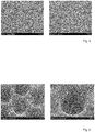
- Fig. 5 shows scanning electron micrographs of inventively hot embossed polycarbonate films. Hot stamping was performed with a lithographic mask obtained from an image and filter Bone marrow structure was created, 50 ⁇ m thick polycarbonate sheets structured with fine structures.
- Fig. 6 shows further scanning electron micrographs of Figure 5 shown polycarbonate films after thermoforming.
- the 50 ⁇ m thick films were additionally structured in a microthermoforming process with a coarse structure.
- molds with cavities were used.
- the cavities of these molds have a diameter of 300 microns and a depth of 300 microns. Due to their size, these structures are very similar to those in the trabecular bone.
- the marked formations come closest to the original.
- FIG. 10 shows a flow chart of a physical surface modification according to a preferred embodiment of the invention.
- FIG. The flowchart shows the sequence of physical surface modification for constructing a hierarchical architecture of a structured substrate to be produced according to the invention.
- Fig. 4 illustrate making a lithographic mask 21, and after processing a wafer 22, a silicone casting 23 of a master is produced, resulting in a film.
- the modification of the film is performed in a hot stamping step 24 with a tool made by applying a lithographic mask formed from a bone marrow structure obtained by imaging and filtering.
- a trabecular bone are impressed in a microthermoforming process, for which purpose a further tool is used, which was created by applying the lithographic mask. This is done in a final process step Applying a nanostructure 26 by dip-coating and incubating the film in a solution or etching.
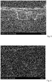
- Fig. 8 shows a scanning electron micrograph of a first preferred embodiment of a replica of stem cell niches of a bone marrow. This embodiment is formed by a structured substrate of polydimethylsiloxane which has been poured off in a mold.
- Fig. 9 shows a scanning electron micrograph of a second preferred embodiment of a replica of stem cell niches of a bone marrow. This embodiment is formed by a patterned substrate of silicon which has been patterned with an embossing tool (not shown).
- Fig. 10 shows a detailed representation of in Fig. 9 shown replica.
- Fig. 11 shows a scanning electron micrograph of a third preferred embodiment of a replica of stem cell niches of a bone marrow. This embodiment is formed by a patterned silicon substrate which has been patterned by reactive ion etching.
- Fig. 12 shows a scanning electron micrograph of a fourth preferred embodiment of a replica of stem cell niches of a bone marrow. This embodiment is formed by a structured substrate made of a borosilicate glass, in which edges have been rounded for structuring.
- Fig. 13 shows a scanning electron micrograph of a fifth preferred embodiment of a replica of stem cell niches of a bone marrow.
- an extracted structure for large-area reproduction is repeatedly strung together.
Landscapes
- Health & Medical Sciences (AREA)
- Life Sciences & Earth Sciences (AREA)
- Engineering & Computer Science (AREA)
- General Physics & Mathematics (AREA)
- Physics & Mathematics (AREA)
- Wood Science & Technology (AREA)
- Biomedical Technology (AREA)
- Organic Chemistry (AREA)
- Bioinformatics & Cheminformatics (AREA)
- Chemical & Material Sciences (AREA)
- Zoology (AREA)
- Biotechnology (AREA)
- Genetics & Genomics (AREA)
- Microbiology (AREA)
- Biochemistry (AREA)
- General Engineering & Computer Science (AREA)
- General Health & Medical Sciences (AREA)
- Cell Biology (AREA)
- Immunology (AREA)
- Sustainable Development (AREA)
- Developmental Biology & Embryology (AREA)
- Rheumatology (AREA)
- Apparatus Associated With Microorganisms And Enzymes (AREA)
- Micro-Organisms Or Cultivation Processes Thereof (AREA)
Description
- Die vorliegende Erfindung betrifft ein Verfahren zum Nachbilden einer Stammzellnische eines Organismus.
- Ein Beispiel für die Aufnahme und Analyse von Stammzell-Morphologien gemäß dem Stand der Technik ist in dem wissenschaftlichen Artikel von Celso, C. L.; Fleming, H. E.; Wu, J. W. et al.: "Live animal tracking of individual stem/progenitor cells in their niche" in Nature, Ausgabe 457, Seiten 92-96, Januar 2009 gezeigt.
- Der Einsatz von Hydrogelen zur Nachbildung von Stammzellnischen findet sich in dem Artikel von Gerecht, S. et al.: "Hyaluronic acid hydrogel for controlled self-renewal and differentiation of human embryonic stem cells" in PNAS, Ausgabe 104, Nr. 27, Seiten 11298-11303, Juli 2007.
- Ein weiterer Ansatz stammt von Hashimoto, Y. et al.: "The effect of decellularized bone/bone marrow produced by highhydrostatic pressurization on the osteogenic differentiation of mesenchymal stem cells" in Biomaterials, Ausgabe 32, Seiten 7060-7067, 2011. Hier werden Knochen menschlichen Ursprungs eingesetzt.
- Eine mikrotechnische Lösung sind Kapillarenarrays, wie sie in dem Artikel von Su, W.-T.: "Ex vivo expansion of a hematopoietic stem cell on a murine stromal cell by 3D micropillar device" in Biomed Microdevices, Ausgabe 13, Seiten 11-17, 2011, aufgeführt sind .
- In dem Artikel von Burke, D. P. et al.: "Substrate stiffness and oxygen availability as regulators of mesenchymal stem sell differentiation within a mechanically loaded bone chamber" in Biomech Model Mechanobiol, Ausgabe 14, Seiten 93-105, 2015, sind Simulationen zum Einfluss mechanischer Faktoren bzw. der Oxigenierung gezeigt.
- Der Artikel von Housler, G. J. et al.: "3-D Perfusion Bioreactor Process Optimization for CD34+ Hematopoietic Stem Cell Culture and Differentiation towards Red Blood Cell Lineage" in Journal of Bone Marrow Research, Ausgabe 2, Nr. 3, 2014, beschreibt einen bioreaktorbasierten Ansatz, bei dem jedoch Hohlfasern genutzt werden.
- Der Artikel von Prendergast, Ä. M. et al.: "Hematopoietic stem cells, infection, and the niche" in Annals of the New York Academy of Sciences, Ausgabe 1310, Seiten 51-57, 2014 beschreibt die Infizierung von Stammzellen in der Stammzellnische.
- Die
US 2015/0118197 A1 zeigt ein Verfahren zur Herstellung eines elektrogesponnenen Gewebes, durch welches beispielsweise die Morphologie einer Nische in den Vogt-Palisaden eines Limbus nachgebildet werden kann. - Die Aufgabe der vorliegenden Erfindung besteht ausgehend vom Stand der Technik darin, verbesserte Kulturbedingungen für Stammzellen schaffen zu können.
- Die genannte Aufgabe wird gelöst durch ein Verfahren gemäß dem beigefügten Anspruch 1.
- Das erfindungsgemäße Verfahren dient zum Nachbilden mindestens einer Stammzellnische eines Organismus. Das erfindungsgemäße Verfahren dient insbesondere zum biolithomorphischen Nachbilden einer Stammzellnische eines Organismus. Bei dem Organismus handelt es sich bevorzugt um einen lebenden Organismus, in welchem die nachzubildende Stammzellnische ausgebildet ist. Bei dem lebenden Organismus handelt es sich insbesondere um ein Tier oder um einen Menschen.
- Die Stammzellnische begrenzt einen Raum, in welchem eine Stammzelle des Gewebes des Organismus leben kann.
- Durch das erfindungsgemäße Verfahren wird insbesondere die Morphologie der mindestens einen Stammzellnische nachgebildet. Daher ist die mindestens eine Stammzellnische im Sinne der Erfindung zumindest durch ihre geometrischen Eigenschaften definiert. Diese geometrischen Eigenschaften beschreiben insbesondere die räumliche Anordnung einer Wandung der Stammzellnische in mindestens zwei Dimensionen. Die Wandung der Stammzellnische umschließt den Raum, in welchem die Stammzelle des Gewebes des Organismus leben kann, nicht vollständig, damit beispielsweise ein Stoffaustausch der Stammzelle ermöglicht ist.
- In einem Schritt des erfindungsgemäßen Verfahrens wird ein Abbild eines Gewebes des Organismus erzeugt. Das Gewebe, welches insbesondere durch Teile eines Organes oder durch ein vollständiges Organ gebildet sein kann, umfasst mindestens eine Stammzellnische. Zumindest diese eine Stammzellnische, aber bevorzugt mehrere der Stammzellnischen sollen erfindungsgemäß nachgebildet werden. Das Gewebe ist bevorzugt durch ein Gewebe eines Knochenmarks des Organismus gebildet. Das Abbild ist zumindest zweidimensional. In diesem Abbild sind u. a. die Wandungen der mindestens einen Stammzellnische abgebildet. Zumeist sind aber auch die Stammzellen und andere Strukturen des Gewebes abgebildet. Das Abbild ist bevorzugt durch eine Vielzahl an Bildpunkten gebildet, wobei jeder Bildpunkt zumindest eine Helligkeitsinformation oder eine Farbinformation besitzt. Das Abbild der der mindestens einen Stammzellnische wird erzeugt, indem ein abbildendes Verfahren auf das Gewebe angewendet wird. Das Abbild wird vor der weiteren Verarbeitung bevorzugt gespeichert.
- In einem weiteren Schritt des erfindungsgemäßen Verfahrens wird das Abbild mithilfe von Methoden der Bildverarbeitung gefiltert, um ein Strukturbild der mindestens einen abgebildeten Stammzellnische zu erhalten. Im Strukturbild sind jedenfalls die Wandungen der mindestens einen Stammzellnische abgebildet. Bevorzugt sind im Strukturbild ausschließlich die Wandungen der mindestens einen Stammzellnische abgebildet. Das Abbild ist bevorzugt durch eine Vielzahl an Bildpunkten gebildet, wobei jedem Bildpunkt bevorzugt eine logische Information von einem Bit zugeordnet ist, ob an diesem Ort eine Wandung gegeben ist oder nicht. Insoweit ist das Strukturbild bevorzugt durch ein Schwarz-Weiß-Bild gebildet. Den Bildpunkten können aber auch einzelne Werte eines eine Vielzahl an Werten umfassenden Wertebereiches zugeordnet sein, um beispielsweise Abstufungen zu repräsentieren. Das Strukturbild ist zumindest zweidimensional. Bei weiteren bevorzugten Ausführungsformen besitzt das Strukturbild 2,5 oder drei Dimensionen.
- In einem weiteren Schritt des erfindungsgemäßen Verfahrens wird aus dem Strukturbild eine lithographische Maske erzeugt. Die lithographische Maske ist dazu ausgebildet, ein formendes Bearbeitungsverfahren zur Strukturierung unmittelbar oder mittelbar ausführen zu können, um gemäß dem Strukturbild zu formen; nämlich um die im Strukturbild gezeigten Wandungen der Stammzellnische durch das formende Bearbeitungsverfahren nachzubilden. Bei dem formenden Bearbeitungsverfahren handelt es sich bevorzugt um ein photolithographisches Verfahren, um ein Prägeverfahren, um ein nanoprägelithographisches Verfahren, um ein heißprägendes Verfahren, um ein thermoformendes Verfahren oder um eine Kombination mehrerer der genannten Verfahren. Entsprechend ist die lithographische Maske beispielsweise dazu ausgebildet, durchleuchtet zu werden oder durch deren Anwendung ein formendes Werkzeug zu erstellen, welches anschließend zum Formen bzw. Strukturieren genutzt wird.
- In einem weiteren Schritt des erfindungsgemäßen Verfahrens wird ein Ausgangsmaterial eines Substrates strukturiert, d. h. geformt, wofür die lithographische Maske mittelbar oder unmittelbar angewendet wird und wodurch mittelbar oder unmittelbar ein strukturiertes Substrat erhalten wird, welches die Nachbildung der mindestens einen abgebildeten Stammzellnische darstellt. Das Strukturieren des Ausgangsmaterials erfolgt mit dem oben beschriebenen formenden Bearbeitungsverfahren. Ist das formende Bearbeitungsverfahren beispielsweise durch ein photolithographisches Verfahren gebildet, so wird die lithographische Maske unmittelbar auf das Ausgangsmaterial angewendet. Ist das formende Bearbeitungsverfahren beispielsweise durch ein nanoprägelithographisches Verfahren oder durch ein heißprägendes Verfahren gebildet, so wird die lithographische Maske mittelbar auf das Ausgangsmaterial angewendet, da mit der lithographischen Maske zunächst ein Werkzeug erstellt wird, welches dann unmittelbar auf das Ausgangsmaterial angewendet wird. Die Nachbildung gleicht der abgebildeten Stammzellnische in ihren geometrischen Eigenschaften, d. h. in ihrer räumlichen Ausdehnung, wobei diese Übereinstimmung in mindestens zwei Dimensionen gegeben ist. Die Nachbildung ist jedoch grundsätzlich dreidimensional ausgebildet, sodass bei einer Übereinstimmung in zwei Dimensionen von einer 2,5-dimensional strukturierten Nachbildung gesprochen werden kann. Insbesondere weist die Nachbildung eine Wandung auf, die in ihrer Ausdehnung der originalen Wandung der abgebildeten Stammzellnische zumindest in zwei Dimensionen gleicht. Die Nachbildung ist bevorzugt mindestens 10 mm lang und 10 mm breit. Die Nachbildung ist bevorzugt mindestens 0,5 mm hoch.
- Die resultierende Nachbildung der mindestens einen abgebildeten Stammzellnische ist als eine biolithomorphische Nachbildung anzusehen. Biolithomorphie ist die Übertragung der Fertigungsprinzipien der Mikro- und Nanotechnologien für die Konstruktion von biologischen dreidimensionalen Geweben für Anwendungen in den "Life Sciences". Dabei sind biologische Morphologien multiskalig auf 2D- und 3D-Substrate zur Zellkultivierung zu übertragen.
- Bei bevorzugten Ausführungsformen der Erfindung wird das Gewebe dem Organismus durch Biopsie entnommen. Es werden bevorzugt Schnitte des entnommenen Gewebes angefertigt, die bevorzugt mit verschiedenen Farben eingefärbt werden, um Strukturen hervorzuheben, insbesondere um die mindestens eine abzubildende Stammzellnische hervorzuheben. Es werden bevorzugt die Wandungen der mindestens einen abzubildenden Stammzellnische hervorgehoben.
- Bei bevorzugten Ausführungsformen der Erfindung umfasst das Strukturbild ein Teilstrukturbild für grobe Strukturen der abgebildeten Stammzellnische und ein Teilstrukturbild für feine Strukturen der abgebildeten Stammzellnische. Die lithographische Maske umfasst dabei eine Teilmaske für grobe Strukturen, die aus dem Teilstrukturbild für grobe Strukturen erzeugt wird. Entsprechend umfasst die lithographische Maske weiterhin eine Teilmaske für feine Strukturen, die aus dem Teilstrukturbild für feine Strukturen erzeugt wird.
- Die feinen Strukturen weisen eine maximale Elementgröße auf, die bevorzugt zwischen 10 µm und 200 µm, besonders bevorzugt zwischen 50 µm und 75 µm beträgt. Die maximale Elementgröße beträgt bevorzugt 50 µm oder alternativ 75 µm. Die feinen Strukturen umfassen ausschließlich Strukturelemente, deren Ausdehnung höchstens so groß wie die maximale Elementgröße ist.
- Die groben Strukturen weisen eine minimale Elementgröße auf, die bevorzugt zwischen 10 µm und 200 µm, besonders bevorzugt zwischen 50 µm und 75 µm beträgt. Die minimale Elementgröße beträgt bevorzugt 50 µm oder alternativ 75 µm. Die groben Strukturen umfassen ausschließlich Strukturelemente, deren Ausdehnung mindestens so groß wie die minimale Elementgröße ist.
- Das Filtern des Abbildes umfasst bevorzugt verschiedene Kantenanalysen, mit denen das Teilstrukturbild für die groben Strukturen und das Teilstrukturbild für die feinen Strukturen bestimmt werden. Zum Bestimmen des Teilstrukturbildes für die groben Strukturen wird bevorzugt ein Tiefpass angewendet. Zum Bestimmen des Teilstrukturbildes für die feinen Strukturen wird bevorzugt ein Hochpass angewendet.
- Bei bevorzugten Ausführungsformen der Erfindung wird mit der lithographischen Maske zunächst ein Werkzeug zum Verformen des Ausgangsmaterials des Substrates erstellt, wobei anschließend das Ausgangsmaterial des Substrates mit dem Werkzeug strukturiert wird.
- Das Werkzeug zum Verformen des Ausgangsmaterials umfasst bevorzugt ein Werkzeug zur Erzeugung grober Strukturen und ein Werkzeug zur Erzeugung feiner Strukturen, wobei das Werkzeug zur Erzeugung grober Strukturen mit der Teilmaske für grobe Strukturen erstellt wird, und wobei das Werkzeug zur Erzeugung feiner Strukturen mit der Teilmaske für feine Strukturen erstellt wird.
- Das Werkzeug zur Erzeugung feiner Strukturen ist bevorzugt durch ein Prägewerkzeug zum Heißprägen, durch ein Prägewerkzeug für eine Nanoprägelithographie, durch eine Form zum Abgießen oder durch eine Form zum Spritzprägen gebildet. Das Werkzeug zur Erzeugung grober Strukturen ist bevorzugt durch ein Thermoformwerkzeug gebildet.
- Das Ausgangsmaterial ist bevorzugt durch eine Folie gebildet. Die Folie ist bevorzugt porös. Das Ausgangsmaterial ist alternativ durch ein Polymer gebildet, welches durch thermoplastische Verformung verformt und strukturiert wird.
- Das Ausgangsmaterial bzw. das Substrat wird bevorzugt mit Bestandteilen einer extrazellulären Matrix der nachzubildenden Stammzellnische beschichtet.
- Das strukturierte Substrat wird bevorzugt mit mindestens einer Stammzelle besiedelt. Die mindestens eine Stammzelle wird im strukturierten Substrat kultiviert.
- Besonders bevorzugt wird ein Schritt durchgeführt, bei welchem die mindestens eine Stammzelle im strukturierten Substrat expandiert. Anschließend wird die mindestens eine expandierte Stammzelle bevorzugt aus dem strukturierten Substrat entnommen und in den individuellen Organismus, dessen Gewebe abgebildet wurde, eingeführt. Insoweit kann diese Ausführungsform der Erfindung auch ein Verfahren zum Expandieren von Stammzellen darstellen.
- Bei einer alternativ bevorzugten Ausführungsform wird ein Schritt durchgeführt, bei welchem die mindestens eine Stammzelle im strukturierten Substrat zu einer Blutzelle ausdifferenziert. Die mindestens eine Blutzelle wird bevorzugt aus dem strukturierten Substrat entnommen und in den individuellen Organismus, dessen Gewebe abgebildet wurde, eingeführt. Insoweit kann diese Ausführungsform der Erfindung auch ein Verfahren zum Ausdifferenzieren von Stammzellen darstellen.
- Die vorliegende Erfindung dient zur organnahen und bevorzugt organgetreuen geometrischen und bevorzugt auch biochemischen Replikation mindestens einer Stammzellnische, die bevorzugt hämatopoetisch ist. Durch die Erfindung kann einer Blutstammzelle in situ eine organnahe geometrische Umgebung geboten werden, die es ermöglicht, diese Blutstammzellen für therapeutische Zwecke gezielt zu expandieren. Durch die Erfindung kann eine hohe Expansionsrate erzielt werden. Ohne eine solche Umgebung neigen die Stammzellen zur Differenzierung und sind für den beabsichtigten therapeutischen Zweck nicht mehr einsetzbar.
- Erfindungsgemäß dient das Abbild eines Gewebes eines Organismus, insbesondere präparierte Schnittbilder vom Knochenmark gesunder Patienten, als Ausgangsmaterial und Vorlagen. Diese werden über Bildverarbeitungstechniken (BV-Techniken) gefiltert und in die lithographische Maske übersetzt und bevorzugt durch Mikrostrukturtechnik abgebildet. Die so bevorzugt entstandene Siliziumstruktur wird bevorzugt über einen Abguss oder über eine galvanische Abformung in das polymere bzw. metallische Werkzeug überführt. Dieses dient dann bevorzugt der weiteren Replikation in dickwandige abgegossene oder in dünnwandige folienbasierte Kultivierungsstrukturen, die als Scaffolds bezeichnet werden können und durch strukturierte Substrate gebildet sind.
- Bei der erfindungsgemäßen Erzeugung des strukturierten Substrates in einer bevorzugten Form eines folienbasierten Scaffolds werden bevorzugt zwei Verfahrensweisen angewendet, um eine sehr hohe Strukturierungstiefe, ähnlich dem nativen Knochenmark, zu erhalten. Eine Foliendicke liegt hier bevorzugt bei max. 75 µm. In einem zweigeteilten BV-Prozess können aus einem Knochenmarkschnitt zuerst verschiedene Strukturgrößen isoliert werden. Dabei wird bevorzugt mit einem Hochpass- und einem Tiefpassfilter gearbeitet. Große Strukturen werden dabei gesondert in die eigene lithografische Maske für grobe Strukturen überführt; ebenso verhält es sich mit kleinen Strukturen. Die Grenze liegt bevorzugt bei 50 µm bis 75 µm Elementgröße. Aus der Maske für die kleinen Strukturen wird ein Prägewerkzeug hergestellt. Dieses Prägewerkzeug besteht bevorzugt aus Metall, Silizium oder einem sehr steifen organischen Material (Photoresist/X-PDMS). Mit diesem Prägewerkzeug wird bevorzugt mittels Heißprägen oder mithilfe der Nanoprägelithografie eine Feinstruktur auf die Folie aufgeprägt, wodurch sie eine Mikrostruktur erhält. Aus der Maske der großen Strukturen im Knochenmarkschnitt wird bevorzugt ein Thermoformwerkzeug hergestellt. Auch hierbei können für das Werkzeug verschiedenen Materialen eingesetzt werden. Die texturierte Folie wird nun in eine Thermoformanlage eingelegt und die Grobstruktur in die Folie eingeformt, sodass sie eine Mesostruktur erhält. Resultat ist das in zunächst zwei Größenordnungen strukturierte Substrat. Dieses kann durch Verwendung eines geeigneten Oberflächenbehandlungsprozesses auch noch bevorzugt nanostrukturiert werden, sodass es eine Nanostruktur erhält. Beispiele hierfür können chemische Ätzung, Plasmamodifikation oder das Aufbringen von Hydrogel- oder anderen organischen Beschichtungen ggf. auch mit Funktionsgruppen sein. Nach erfolgter Oberflächenmodifikation liegt das Substrat mit der Meso-, der Mikro- und der Nanostruktur vor.
- Die Verwendung einer porösen Folie als Halbzeug ermöglicht zudem auch die Herstellung eines durchströmbaren Scaffolds.
- Nachfolgend sind weitere bevorzugte Ausführungsformen der Erfindung beschrieben.
- Zum Erzeugen des Abbildes eines mindestens eine Stammzellnische umfassenden Gewebes eines Organismus werden bevorzugt Schnittbilder als das Abbild des Gewebes des lebenden Organismus hergestellt. Bei dem lebenden Organismus handelt es sich bevorzugt um ein Tier oder um einen Menschen. Hierfür wird bevorzugt zunächst Gewebe in Form von Knochenmark mittels Biopsie gewonnen. Es werden pathologische Mikroschnitte mit einer Schnittdicke von etwa 10 µm angefertigt und diese mit Hämatoxylin-Eosin gefärbt. Es erfolgt bevorzugt eine verschiedenartige Färbung von Knochenmarkstruktur, die weiches Gewebe, mindestens eine extrazelluläre Matrix, und eine Spongiosa-Struktur, d. h. harte Knochenstruktur umfasst.
- In einem weiteren bevorzugt durchzuführenden Schritt erfolgt ein Digitalisieren der Schnittbilder in mikroskopische Aufnahmen. Bevorzugt erfolgt ein Digitalisieren der einzelnen verschiedenen Färbungen, sodass mehrere Bilder entstehen. Alternativ bevorzugt erfolgen zunächst ein Digitalisieren in einzelnes Bild und ein späteres Erkennen und Trennen der Strukturen durch Anwenden von Methoden der Bildverarbeitung. Bei der Bildverarbeitung erfolgt bevorzugt zunächst ein Erzeugen von Graustufenbildern aus den digitalisierten Schnittbildern. Es werden mindestens ein Hochpass und/oder ein Tiefpass auf die Graustufenbilder angewendet, um die Graustufenbilder in eine Grobstruktur und in eine Feinstruktur zu trennen. Bevorzugt erfolgt weiterhin eine Kantendetektion unter Nutzung von Kantenfindungsalgorithmen, wie z. B. der Canny- oder Niblack-Algorithmus, und/oder unter Nutzung einer Schwellwertbildung. Aus den detektierten Kanten wird bevorzugt jeweils ein Schwarz-Weiß Bild erstellt. Das mindestens eine Schwarz-Weiß-Bild wird bevorzugt vektorisiert.
- Zum Erzeugen der lithographischen Maske wird das vektorisierte Bild der detektierten Kanten überführt. Bevorzugt wird das vektorisierte Bild der detektierten Kanten durch ein mehrfaches Anreihen, Spiegeln oder Rotatieren vergrößert.
- In einem weiteren bevorzugt durchzuführenden Schritt wird das Werkzeug zur Abformung erstellt. Hierfür wird die lithographische Maske bevorzugt prozessiert, z. B. als Hellfeld oder Dunkelfeld, was in verschiedenen Materialsystemen, wie Silizium oder Glas und unter Nutzung verschiedener Technologien, wie z. B. nasschemische oder trockenchemische Technologien erfolgen kann. Bevorzugt erfolgt eine Beeinflussung von Ätztiefe, Strukturauflösung und Kantenverrundung. Das Prozessieren der lithographischen Maske führt beispielsweise zu einem prozessierten Wafer, der bevorzugt mit einer galvanischen Startschicht für eine nachfolgende galvanische Abformung oder mit einer Anti-Adhäsionsschicht für einen nachfolgenden Abguss oder für eine nachfolgende Abformung beschichtet wird. Das Werkzeug zur Abformung ist bevorzugt direkt durch die geätzten Strukturen, durch deren galvanische Abformungen oder durch deren Abgüsse, z. B. aus hartem Silikon oder einem Epoxid-Harz, gebildet.
- Das strukturierte Substrat, welches auch als Kultursubstrat bezeichnet werden kann, wird durch Nutzung des Werkzeuges zur Abformung erhalten. Dabei erfolgt bevorzugt eine Replikation des Werkzeuges zur Abformung. Diese Replikation erfolgt bevorzugt durch ein Abgießen. Das mindestens eine Kultursubstrat wird durch einen direkten Abguss repliziert und dann zur Kultivierung verwendet. Das Kultursubstrat ist massiv und weist an der Oberfläche eine Strukturierung auf. Bevorzugt wird durch eine flächige Beschichtung oder durch eine Schattenmaske ergänzend eine Nanostruktur auf das Kultursubstrat aufgebracht, was bevorzugt durch eine physikalische Gasphasenabscheidung erfolgt. Die Replikation erfolgt alternativ bevorzugt durch eine einfache Abformung. Das Werkzeug zur Abformung wird genutzt, um Strukturen durch ein Heißprägen oder durch ein Thermoformen abzuformen. Es entstehen einfach strukturierte Substrate aus massiven Körpern beim Heißprägen bzw. aus dünnen Folien beim Thermoformen. Die Folien sind bevorzugt porös. In einem weiteren bevorzugt durchzuführenden Schritt wird auf das Substrat eine flächige Beschichtung oder mithilfe einer Schattenmaske eine Nanostruktur aufgebracht. Die Replikation erfolgt alternativ bevorzugt durch eine mehrfache Abformung. Bei dieser Ausführungsform werden bevorzugt Folien mit einer Ausgangsdicke von maximal 100 µm verwendet. Diese Folien sind bevorzugt porös. Zunächst wird die Feinstruktur durch Heißprägen in die Oberfläche der Folie eingeprägt, wofür das Werkzeug zur Erzeugung feiner Strukturen genutzt wird. Dabei beträgt ein Aspektverhältnis bevorzugt maximal 3. Die feinstrukturierte Folie wird mit ihrer unstrukturierten Seite in eine das Werkzeug zur Erzeugung grober Strukturen bildende Thermoformmaschine eingelegt und durch Aufheizen und durch einen Druckstoß grob strukturiert. In einem weiteren bevorzugt durchzuführenden Schritt wird durch eine flächige Beschichtung oder durch eine Schattenmaske noch eine Nanostruktur auf das strukturierte Substrat aufgebracht.
- In einem weiteren bevorzugt durchzuführenden Schritt des erfindungsgemäßen Verfahrens erfolgt eine Kultivierung von Stammzellen in dem strukturierten Substrat. Das strukturierte Substrat stellt bevorzugt ein statisches System dar. Das strukturierte Substrat, insbesondere wenn es massiv ausgeführt ist, wird in ein einfaches Kulturgefäß eingebracht und mit der Stammzellkultur besiedelt. Dabei wird bevorzugt ein periodischer Medientausch durchgeführt. Das strukturierte Substrat stellt bevorzugt ein durchströmtes System dar. Das Substrat, insbesondere wenn es folienbasiert und porös ausgebildet ist, wird bevorzugt in einem Bioreaktorsystem perfundiert betrieben. Dazu werden Zellkulturen auf das Substrat aufgebracht und nach einer kurzen Adhärenzzeit wird das Substrat in das Bioreaktorsystem eingebracht und mit einer entsprechenden Flussmenge durchströmt. Der Medienaustausch kann hierbei periodisch, kontinuierlich oder periodisch partiell sein. Das Substrat, insbesondere wenn es folienbasiert, massiv und unporös ausgebildet ist, wird bevorzugt in einer Superfusion betrieben. Dazu werden Zellkulturen auf das Substrat aufgebracht und nach einer kurzen Adhärenzzeit wird das Substrat in das Bioreaktorsystem eingebracht und mit einer entsprechenden Flussmenge überströmt. Der Medienaustausch kann hierbei periodisch, kontinuierlich oder periodisch partiell sein.
- Es ist schon lange bekannt, dass die dreidimensionale Struktur des Mikromilieus einer Stammzelle einen wesentlichen Faktor für die Regulation der Hämatopoese darstellt. So konnte gezeigt werden, dass eine Desintegration von Knochenmarkbröckchen nach einer Collagenasebehandlung zum vollständigen Erlöschen der Hämatopoese in der anschließenden Kultur führt, während aus intakten Bröckchen selbst ohne externe Wachstumsfaktorgabe schon nach kurzer Zeit Stroma mit hämatopoetischen Inseln auswächst. Ein Defekt nach Collagenasebehandlung lässt sich nur ansatzweise durch Wachstumsfaktoren (SCF, IL3, Epo) kompensieren. Überraschend ist daher, dass bereits eine 2,5D-artige Struktur in Form eines erfindungsgemäß strukturierten Substrates eine wesentlich erhöhte Vitalität und Expansion der Stammzellen ermöglicht.
- Wie schon ausgeführt, können beim erfindungsgemäßen Verfahren unterschiedliche Materialien als Ausgangsmaterial für das Substrat eingesetzt werden. Sowohl organische wie auch anorganische Materialien können dabei über eine geeignete Kopplungschemie mit zellspezifischen Molekülen vorteilhaft beschichtet werden. Eine alternativ bevorzugte Ausführungsform umfasst ein verfahrenstechnisches Auftragen, z. B. über "spincoating" von zellverträglichen Materialien, vorzugsweise von Bestandteilen der extrazellulären Matrix, wie z. B. Kollagen. Das Auftragen erfolgt vorzugsweise im Falle polymerer Substrate auf das Ausgangsmaterial. Das Auftragen erfolgt alternativ bevorzugt durch Tauchverfahren, wobei das Auftragen auf das bereits geformte Substrat erfolgt. Besonders bevorzugt erfolgt eine chemische Modifikation des 3D- bzw. 2,5D-strukturierten Substrates mit Zelladhäsionsmolekülen. Die Zelladhäsionsmoleküle sind bevorzugt durch geeignete Peptidsequenzen, z. B. aus der Familie der RGD Motive gebildet.
- Im lebenden Körper werden aus biologischen Phosphaten, wie z. B. Glucose-6-phosphat, in die umgebende Matrix kontinuierlich Phosphationen freigesetzt. Durch das gleichfalls vorliegende Calcium kommt es beim Überschreiten des Löslichkeitsprodukts zur Kristallisation von Calciumphosphat und Ausbildung einer Knochenstruktur. Erfindungsgemäß wird bevorzugt ein polymeres Ausgangsmaterial verwendet, welches auch solche kristallinen Materialien enthält, wie sie im Knochen vorliegen.
- Bei einer weiteren bevorzugten Ausführungsform erfolgt eine Konfektionierung bzw. Synthese des vorzugsweisen polymeren Substrates für die Stammzellkultivierung derart, dass ein Folie aus einer Kollagenmatrix und Hydroxylapatit (Ca5[OH|(PO4)3]) als Ausgangsmaterial bereitgestellt wird und dann der gezeigten Strukturierung unterworfen wird.
- Bei weiteren bevorzugten Ausführungsformen wird ein synthetisches Material wie z. B. eine synthetische Nanokompositstruktur, die beispielsweise aus verkieselten Poly(N-isopropylacrylamide)/Hydroxyapatit besteht, als Ausgangsmaterial für das Substrat genutzt.
- Die genannten konfektionierten Polymere werden bevorzugt wiederum einer chemischen Modifikation unterzogen; vorzugsweise durch Zellkontakt vermittelnde Peptide oder durch andere Substanzen.
- Bei einer weiteren bevorzugten Ausführungsform können unterschiedliche Ladungen durch Beschichtungen des Ausgangsmaterials bzw. des Substrates mit vorzugsweise Apatitanalogen Kristallen oder mit Hyaluronsäure-Hydrogelen mit jeweils unterschiedlicher Dotierung erfolgen. Die Vernetzung kann über die Einführung bisfunktioneller organischer Moleküle erfolgen. Dadurch gelingt auch die Kopplung von VLA4/VCAM, beta1-Integrin, WNT, IL6, SCF und CXCL12.
- Des Weiteren werden bevorzugt durch Modifikationen im Polymer des Ausgangsmaterials bzw. des Substrates Gradienten von biologischen Effektormolekülen vorgelegt.
- Das erzeugte Substrat wird bei bevorzugten Ausführungsformen der Erfindung in einen Systemaufbau eingebracht, der unterschiedliche physiologische Bedingungen, vorzugsweise auch die des Knochenmarks, simulieren kann. So besteht auch neben den oben beschriebenen biochemischen Modifikationen des Substrates hinsichtlich des Ausgangsmaterials, der Oberflächen, der Wachstumsfaktoren, der Adhäsionsproteine etc. eine vorteilhafte Möglichkeit die Kulturbedingungen, wie normoxische und hypoxische Zustände, durch geeignete Klimatisierung bzw. Fluidik einzustellen bzw. Wachstumsfaktoren und chemische/biochemische Effektorstoffe zu applizieren.
- Eine bevorzugte synthetische Nachbildung mindestens einer Stammzellnische eines Organismus weist geometrische Eigenschaften der mindestens einen Stammzellnische des Organismus auf. Die Nachbildung umfasst zumindest eine Wandung, welche einer Wandung der Stammzellnische des Organismus in mindestens zwei Dimensionen nachgebildet ist und dieser gleicht. Diese Nachbildung weist somit die Morphologie der Stammzellnische des Organismus auf. Diese Nachbildung weist bevorzugt eine Mesostruktur als eine grobe Struktur und eine Mikrostruktur als eine feine Struktur sowie weiterhin bevorzugt eine Nanostruktur als eine weitere feine Struktur auf. Die grobe Struktur und die feine Struktur weisen bevorzugt die im Zusammenhang mit dem erfindungsgemäßen Verfahren beschriebenen Merkmale auf. Im Übrigen weist die Nachbildung bevorzugt auch solche Merkmale auf, die im Zusammenhang mit dem erfindungsgemäßen Verfahren beschrieben sind.
- Weitere Vorteile, Einzelheiten und Weiterbildungen der Erfindung ergeben sich aus der nachfolgenden Beschreibung bevorzugter Ausführungsformen der Erfindung, unter Bezugnahme auf die Zeichnungen. Es zeigen:
- Fig. 1:
- ein erfindungsgemäß erstelltes strukturiertes Substrat in einer Querschnittsdarstellung;
- Fig. 2:
- ein erfindungsgemäß erstelltes Originalbild eines Knochenmarksabschnittes und daraus erfindungsgemäß erzeugte Strukturbilder;
- Fig. 3:
- einen Vergleich zwischen dem in
Fig. 2 gezeigten Originalbild und einem erfindungsgemäß erstellten Strukturbild; - Fig. 4:
- ein Flussdiagramm einer erfindungsgemäßen Erzeugung lithographischer Masken;
- Fig. 5:
- erfindungsgemäß feinstrukturierte Polycarbonatfolien;
- Fig. 6:
- die in
Fig. 5 gezeigten Polycarbonatfolien mit ergänzenden groben Strukturen; - Fig. 7:
- ein Flussdiagramm einer physikalischen Oberflächenmodifikation gemäß einer bevorzugten Ausführungsform der Erfindung;
- Fig. 8:
- eine erste bevorzugte Ausführungsform einer Nachbildung von Stammzellnischen eines Knochenmarks;
- Fig. 9:
- eine zweite bevorzugte Ausführungsform einer Nachbildung von Stammzellnischen eines Knochenmarks;
- Fig. 10:
- eine Detaildarstellung der in
Fig. 9 gezeigten Nachbildung; - Fig. 11:
- eine dritte bevorzugte Ausführungsform einer Nachbildung von Stammzellnischen eines Knochenmarks;
- Fig. 12:
- eine vierte bevorzugte Ausführungsform einer Nachbildung von Stammzellnischen eines Knochenmarks; und
- Fig. 13:
- eine fünfte bevorzugte Ausführungsform einer Nachbildung von Stammzellnischen eines Knochenmarks in einer Anreihung.
-
Fig. 1 zeigt das Ziel einer bevorzugten Ausführungsform des erfindungsgemäßen Verfahrens in einer Querschnittsdarstellung, nämlich der Aufbau einer hierarchischen Struktur in Form eines strukturierten Substrates, welches eine Vielzahl an Stammzellnischen eines biologischen Gewebes eines Organismus synthetisch nachbildet, bestehend aus einer groben Mesostruktur 01, einer feinen Mikrostruktur 02 und einer noch feineren Nanostruktur 03. Hierfür werden bevorzugt thermoplastische Folien mit unterschiedlichen Methoden strukturiert. Anschließend erfolgt eine Kultivierung von hämatopoietischen Stammzellen (nicht dargestellt) mit dem Ziel der Aufrechterhaltung ihres undifferenzierten Status. -
Fig. 2 zeigt ein erfindungsgemäß erstelltes Originalbild A eines Knochenmarksabschnittes und daraus erfindungsgemäß erzeugte Binärbilder B, C, D, E nach Anwendung von Kantendetektor-Algorithmen. Die Binärbilder B, C, D, E stellen Strukturbilder dar, welche ausgehend von dem Originalbild A gewonnen wurden. Die Binärbilder B, C, D, E zeigen Kanten, welche Wandungen von Stammzellnischen im Knochenmark repräsentieren. Die Kanten wurden aus dem Originalbild A, welches ein Grauwert- oder RGB-Bild sein kann, mit verschiedenen Algorithmen detektiert. -
Fig. 3 zeigt einen Vergleich zwischen dem bereits inFig. 2 gezeigten Originalbild A und einem erfindungsgemäß erstellten Binärbild nach Anwendung des Canny-Detektors. Es sind das Originalbild des Knochenmarkschnittes A und das Originalbild mit überlagerten, extrahierten Strukturen nach einer Kantendetektion mit dem Canny-Detektor B dargestellt. -
Fig. 4 zeigt ein Flussdiagramm einer Erzeugung lithographischer Masken aus Daten eines Abbildes eines mindestens eine Stammzellnische umfassenden Gewebes gemäß einer bevorzugten Ausführungsform der Erfindung. Das Flussdiagramm beschreibt den Ablauf der Extrahierung von Strukturen aus einer Bilddatei unter der Verwendung von verschiedenen Algorithmen der Binärbilderstellung und deren Verwendung im Design einer Photomaske. Nach einer Auswahl 11 einer Bilddatei und Einlesen 12 der Daten der Bilddatei in ein Computerprogramm zur Lösung mathematischer Probleme wird die Bilddatei aus dem RGB-Farbraum bzw. aus einem Grauwertbereich in ein Binärbild 13 umgewandelt. Durch Verwendung eines Kantendetektionsalgorithmus 14 und einer lokalen Schwellenwertberechnung 16 werden Strukturbilder gewonnen. Es erfolgt eine Auswahl 17 der geeignetsten Strukturbilder. Die Strukturbilder werden einer Vektorisierung 18 unterzogen, sodass Vektordaten gewonnen werden. Aus den Vektordaten werden lithographische Masken 19 erstellt. -
Fig. 5 zeigt Rasterelektronenmikroskopaufnahmen von erfindungsgemäß heißgeprägten Polycarbonatfolien. Durch Heißprägen wurden mit einer lithographischen Maske, die aus einer durch Abbilden und Filtern erhaltenen Knochenmarkstruktur erstellt wurde, 50 µm dicke Polycarbonatfolien mit feinen Strukturen strukturiert. -
Fig. 6 zeigt weitere Rasterelektronenmikroskopaufnahmen der inFig.5 gezeigten Polycarbonatfolien nach einem Thermoformen. Nach dem Heißprägen mit einer durch Abbilden und Filtern erhaltenen Knochenmarkstruktur wurden die 50 µm dicken Folien in einem Mikrothermoformprozess ergänzend mit einer groben Struktur strukturiert. Dafür wurden Formwerkzeuge mit Kavitäten verwendet. Die Kavitäten dieser Formwerkzeuge haben einen Durchmesser von 300 µm und eine Tiefe von ebenfalls 300 µm. Damit sind diese Strukturen aufgrund ihrer Größe denen im trabekulären Knochen sehr ähnlich. Dabei kommen die markierten Ausformungen dem Original am nächsten. -
Fig. 7 zeigt ein Flussdiagramm einer physikalischen Oberflächenmodifikation gemäß einer bevorzugten Ausführungsform der Erfindung. Das Flussdiagramm zeigt den Ablauf der physikalischen Oberflächenmodifikation zum Aufbau einer hierarchischen Architektur eines erfindungsgemäß herzustellenden strukturierten Substrates. Nach der inFig. 4 veranschaulichen Erstellung einer lithographischen Maske 21 und nach einer Prozessierung eines Wafers 22 wird ein Silikonabguss 23 eines Masters hergestellt, wodurch eine Folie resultiert. Danach erfolgt die Modifikation der Folie in einem Heißprägeschritt 24 mit einem Werkzeug, welches durch Anwenden einer lithographischen Maske erstellt wurde, die aus einer durch Abbilden und Filtern erhaltenen Struktur eines Knochenmarks erzeugt wurde. Anschließend werden in einem Mikrothermoformprozess 25 Strukturen eines trabekulären Knochens eingeprägt, wofür ein weiteres Werkzeug verwendet wird, welches durch Anwenden der lithographischen Maske erstellt wurde. In einem finalen Prozessschritt erfolgt das Aufbringen einer Nanostruktur 26 durch Dip-Coating und Inkubieren der Folie in einer Lösung oder Ätzen. -
Fig. 8 zeigt eine Rasterelektronenmikroskopaufnahme einer ersten bevorzugten Ausführungsform einer Nachbildung von Stammzellnischen eines Knochenmarks. Diese Ausführungsform ist durch ein strukturiertes Substrat aus Polydimethylsiloxan gebildet, welches in einer Form abgegossen wurde. -
Fig. 9 zeigt eine Rasterelektronenmikroskopaufnahme einer zweiten bevorzugten Ausführungsform einer Nachbildung von Stammzellnischen eines Knochenmarks. Diese Ausführungsform ist durch ein strukturiertes Substrat aus Silicium gebildet, welches mit einem Prägewerkzeug (nicht gezeigt) strukturiert wurde. -
Fig. 10 zeigt eine Detaildarstellung der inFig. 9 gezeigten Nachbildung. -
Fig. 11 zeigt eine Rasterelektronenmikroskopaufnahme einer dritten bevorzugten Ausführungsform einer Nachbildung von Stammzellnischen eines Knochenmarks. Diese Ausführungsform ist durch ein strukturiertes Substrat aus Silicium gebildet, welches durch ein reaktives Ionenätzen strukturiert wurde. -
Fig. 12 zeigt eine Rasterelektronenmikroskopaufnahme einer vierten bevorzugten Ausführungsform einer Nachbildung von Stammzellnischen eines Knochenmarks. Diese Ausführungsform ist durch ein strukturiertes Substrat aus einem Borosilikatglas gebildet, bei welchem zur Strukturierung Kanten verrundet wurden. -
Fig. 13 zeigt eine Rasterelektronenmikroskopaufnahme einer fünften bevorzugten Ausführungsform einer Nachbildung von Stammzellnischen eines Knochenmarks. Bei dieser Ausführungsform ist eine extrahierte Struktur zur großflächigen Reproduktion mehrfach aneinandergereiht. -
- 01
- Mesostruktur
- 02
- Mikrostruktur
- 03
- Nanostruktur
- 04
- -
- 05
- -
- 06
- -
- 07
- -
- 08
- -
- 09
- -
- 10
- -
- 11
- Auswahl einer Bilddatei
- 12
- Einlesen der Daten der Bilddatei
- 13
- Binärbild
- 14
- Kantendetektionsalgorithmus
- 15
- -
- 16
- lokale Schwellenwertberechnung
- 17
- Auswahl der geeignetsten Strukturbilder
- 18
- Vektorisierung
- 19
- lithographische Masken
- 20
- -
- 21
- Erstellung einer lithographischen Maske
- 22
- Prozessierung eines Wafers
- 23
- Silikonabguss
- 24
- Heißprägeschritt
- 25
- Mikrothermoformprozess
- 26
- Aufbringen einer Nanostruktur
Claims (8)
- Verfahren zum Nachbilden einer Stammzellnische eines Organismus, folgende Schritte umfassend:- Erzeugen eines Abbildes eines mindestens eine Stammzellnische umfassenden Gewebes eines Organismus;- Filtern (16, 17) des Abbildes, um ein Strukturbild der abgebildeten Stammzellennische zu erzeugen;- Erzeugen (21) einer lithographischen Maske (19) aus dem Strukturbild; und- Strukturieren (22, 23, 24, 25, 26) eines Ausgangsmaterials eines Substrates durch Anwenden der lithographischen Maske (19), wodurch ein strukturiertes Substrat erhalten wird, welches die Nachbildung der abgebildeten Stammzellnische des Organismus darstellt.
- Verfahren nach Anspruch 1, dadurch gekennzeichnet, dass das Strukturbild ein Teilstrukturbild für grobe Strukturen der abgebildeten Stammzellnische und ein Teilstrukturbild für feine Strukturen der abgebildeten Stammzellnische umfasst; wobei die lithographische Maske (19) eine Teilmaske für grobe Strukturen umfasst, die aus dem Teilstrukturbild für grobe Strukturen erzeugt wird; und wobei die lithographische Maske (19) eine Teilmaske für feine Strukturen umfasst, die aus dem Teilstrukturbild für feine Strukturen erzeugt wird.
- Verfahren nach Anspruch 2, dadurch gekennzeichnet, dass die feinen Strukturen eine maximale Elementgröße zwischen 50 µm und 75 µm aufweisen, und dass die groben Strukturen eine minimale Elementgröße zwischen 50 µm und 75 µm aufweisen.
- Verfahren nach Anspruch 2 oder 3, dadurch gekennzeichnet, dass das Filtern (16, 17) des Abbildes verschiedene Kantenanalysen umfasst, mit denen das Teilstrukturbild für die groben Strukturen und das Teilstrukturbild für die feinen Strukturen bestimmt werden.
- Verfahren nach einem der Ansprüche 1 bis 4, dadurch gekennzeichnet, dass mit der lithographischen Maske (19) zunächst ein Werkzeug zum Verformen des Ausgangsmaterials des Substrates erstellt wird, wobei anschließend das Ausgangsmaterial des Substrates mit dem Werkzeug strukturiert wird.
- Verfahren nach dem auf Anspruch 2 rückbezogenen Anspruch 5, dadurch gekennzeichnet, dass das Werkzeug zum Verformen des Ausgangsmaterials ein Werkzeug zur Erzeugung grober Strukturen und ein Werkzeug zur Erzeugung feiner Strukturen umfasst, wobei das Werkzeug zur Erzeugung grober Strukturen mit der Teilmaske für grobe Strukturen erstellt wird, und wobei das Werkzeug zur Erzeugung feiner Strukturen mit der Teilmaske für feine Strukturen erstellt wird.
- Verfahren nach Anspruch 6, dadurch gekennzeichnet, dass das Werkzeug zur Erzeugung feiner Strukturen durch ein Prägewerkzeug zum Heißprägen oder durch ein Prägewerkzeug für eine Nanoprägelithografie gebildet ist, und dass das Werkzeug zur Erzeugung grober Strukturen durch ein Thermoformwerkzeug gebildet ist.
- Verfahren nach einem der Ansprüche 1 bis 7, dadurch gekennzeichnet, dass das strukturierte Substrat mit mindestens einer Stammzelle besiedelt wird.
Applications Claiming Priority (3)
| Application Number | Priority Date | Filing Date | Title |
|---|---|---|---|
| DE102015108566 | 2015-05-29 | ||
| DE102015122375.9A DE102015122375A1 (de) | 2015-05-29 | 2015-12-21 | Nachbildung einer Stammzellnische eines Organismus sowie Verfahren zu deren Erzeugung |
| PCT/EP2016/061883 WO2016193107A1 (de) | 2015-05-29 | 2016-05-26 | Nachbildung einer stammzellnische eines organismus sowie verfahren zu deren erzeugung |
Publications (2)
| Publication Number | Publication Date |
|---|---|
| EP3304207A1 EP3304207A1 (de) | 2018-04-11 |
| EP3304207B1 true EP3304207B1 (de) | 2019-07-03 |
Family
ID=57282119
Family Applications (1)
| Application Number | Title | Priority Date | Filing Date |
|---|---|---|---|
| EP16728860.4A Active EP3304207B1 (de) | 2015-05-29 | 2016-05-26 | Nachbildung einer stammzellnische eines organismus sowie verfahren zu deren erzeugung |
Country Status (4)
| Country | Link |
|---|---|
| US (1) | US10780613B2 (de) |
| EP (1) | EP3304207B1 (de) |
| DE (1) | DE102015122375A1 (de) |
| WO (1) | WO2016193107A1 (de) |
Families Citing this family (1)
| Publication number | Priority date | Publication date | Assignee | Title |
|---|---|---|---|---|
| DE102022108006A1 (de) | 2022-04-04 | 2023-10-05 | Technische Universität Ilmenau, Körperschaft des öffentlichen Rechts | Nachbildung und Verfahren zum dreidimensionalen Nachbilden eines biologischen Gewebes |
Family Cites Families (9)
| Publication number | Priority date | Publication date | Assignee | Title |
|---|---|---|---|---|
| DK2347775T3 (da) | 2005-12-13 | 2020-07-13 | Harvard College | Skabeloner til celletransplantation |
| US7772575B2 (en) * | 2006-11-21 | 2010-08-10 | D2S, Inc. | Stencil design and method for cell projection particle beam lithography |
| CN102105578A (zh) * | 2008-05-30 | 2011-06-22 | 康宁股份有限公司 | 具有可变表面形状的细胞培养装置 |
| EP2266635A1 (de) | 2009-06-26 | 2010-12-29 | Aarhus Universitet | Hybridgerüst mit dreidimensionaler Nanostruktur und Herstellung davon |
| EP3073322B1 (de) | 2009-09-30 | 2020-07-01 | SNU R & DB Foundation | Auf bildverarbeitung beruhendes lithografiesystem und zielobjektbeschichtungsverfahren |
| WO2011135566A1 (en) * | 2010-04-27 | 2011-11-03 | Yeda Research And Development Co. Ltd. | Niche system for biological culturing |
| GB201207723D0 (en) | 2012-05-02 | 2012-06-13 | Univ Sheffield | Scaffold |
| US20150118729A1 (en) * | 2013-10-29 | 2015-04-30 | The Board Of Trustees Of The University Of Illinois | Cell programing via geometric cues |
| WO2016019078A1 (en) * | 2014-07-30 | 2016-02-04 | Tufts University | Three dimensional printing of bio-ink compositions |
-
2015
- 2015-12-21 DE DE102015122375.9A patent/DE102015122375A1/de not_active Ceased
-
2016
- 2016-05-26 US US15/578,214 patent/US10780613B2/en active Active
- 2016-05-26 EP EP16728860.4A patent/EP3304207B1/de active Active
- 2016-05-26 WO PCT/EP2016/061883 patent/WO2016193107A1/de not_active Ceased
Non-Patent Citations (1)
| Title |
|---|
| None * |
Also Published As
| Publication number | Publication date |
|---|---|
| US10780613B2 (en) | 2020-09-22 |
| EP3304207A1 (de) | 2018-04-11 |
| DE102015122375A1 (de) | 2016-12-01 |
| WO2016193107A1 (de) | 2016-12-08 |
| US20180147751A1 (en) | 2018-05-31 |
Similar Documents
| Publication | Publication Date | Title |
|---|---|---|
| Chen et al. | A matrigel-free method to generate matured human cerebral organoids using 3D-Printed microwell arrays | |
| Amukarimi et al. | 4D bioprinting of tissues and organs | |
| Yang et al. | High-throughput methods in the discovery and study of biomaterials and materiobiology | |
| DE60017900T2 (de) | Herstellung von dreidimensionalem vaskularisierten gewebe mittels der verwendung von zweidimensionalen mikrohergestellten formen | |
| EP2569141B1 (de) | Verfahren zur herstellung einer organnachbildung, insbesondere eines funktionsmodells | |
| Malinauskas et al. | 3D artificial polymeric scaffolds for stem cell growth fabricated by femtosecond laser | |
| Yadav et al. | Biomimicked hierarchical 2D and 3D structures from natural templates: applications in cell biology | |
| EP3907007A1 (de) | Mikrofluidische vorrichtung | |
| EP2167641B1 (de) | Verfahren und vorrichtung zur bildung einer dreidimensionalen anordnung biologischer zellen | |
| Sung et al. | Probing neural cell behaviors through micro-/nano-patterned chitosan substrates | |
| DE102015122375A1 (de) | Nachbildung einer Stammzellnische eines Organismus sowie Verfahren zu deren Erzeugung | |
| Cortella et al. | Conditioning of hiPSC-derived cardiomyocytes using surface topography obtained with high throughput technology | |
| WO2011052281A1 (ja) | 神経スフェロイドネットワークの構築方法 | |
| DE19919242A1 (de) | Modulare Zellträgersysteme für dreidimensionales Zellwachstum | |
| DE102017207698B4 (de) | Neuronal induktive Kultivierungsmatrix | |
| El-Tamer et al. | Development of in vitro 3D brain models on laser fabricated scaffolds | |
| DE102010022675B4 (de) | Verfahren zur Herstellung einer Hydrogel-Mikrostruktur | |
| Minnick et al. | Microfluidic Topography Biases Neural Organoid Morphogenesis | |
| EP3851516A1 (de) | Verfahren und vorrichtung zur kultivierung und untersuchung von neuronen | |
| DE19919241A1 (de) | 3D Zellträgersystem für Zell-, Gewebe- und Organkulturen | |
| CN113820917B (zh) | 一种纳米压印的各向异性石墨烯薄膜的制备方法 | |
| DE102013012467A1 (de) | Verkapselungseinrichtung und -verfahren zur Verkapselung einer Probe in einer Polymerkapsel | |
| DE102006006808A1 (de) | Nanobiotechnologische Vorrichtung für Anatomiestrukturnachbildungen | |
| DE102019123799B4 (de) | Verfahren zur Herstellung von Biomaterialien mit porösen und glatten Topographien und deren Verwendung | |
| DE102022108006A1 (de) | Nachbildung und Verfahren zum dreidimensionalen Nachbilden eines biologischen Gewebes |
Legal Events
| Date | Code | Title | Description |
|---|---|---|---|
| STAA | Information on the status of an ep patent application or granted ep patent |
Free format text: STATUS: THE INTERNATIONAL PUBLICATION HAS BEEN MADE |
|
| PUAI | Public reference made under article 153(3) epc to a published international application that has entered the european phase |
Free format text: ORIGINAL CODE: 0009012 |
|
| STAA | Information on the status of an ep patent application or granted ep patent |
Free format text: STATUS: REQUEST FOR EXAMINATION WAS MADE |
|
| 17P | Request for examination filed |
Effective date: 20171227 |
|
| AK | Designated contracting states |
Kind code of ref document: A1 Designated state(s): AL AT BE BG CH CY CZ DE DK EE ES FI FR GB GR HR HU IE IS IT LI LT LU LV MC MK MT NL NO PL PT RO RS SE SI SK SM TR |
|
| AX | Request for extension of the european patent |
Extension state: BA ME |
|
| RIN1 | Information on inventor provided before grant (corrected) |
Inventor name: FERNEKORN, UTA Inventor name: HAMPL, JOERG Inventor name: WEISE, FRANK Inventor name: MUELLER, ANGELIKA Inventor name: BECK, JAMES Inventor name: SCHOBER, ANDREAS Inventor name: HAEFNER, SEBASTIAN Inventor name: SCHLINGLOFF, GREGOR Inventor name: VOIGT, ASTRID Inventor name: SINGH, SUKHDEEP Inventor name: BOROWIEC, JUSTYNA Inventor name: GEBINOGA, MICHAEL |
|
| DAV | Request for validation of the european patent (deleted) | ||
| DAX | Request for extension of the european patent (deleted) | ||
| GRAP | Despatch of communication of intention to grant a patent |
Free format text: ORIGINAL CODE: EPIDOSNIGR1 |
|
| STAA | Information on the status of an ep patent application or granted ep patent |
Free format text: STATUS: GRANT OF PATENT IS INTENDED |
|
| INTG | Intention to grant announced |
Effective date: 20181211 |
|
| GRAS | Grant fee paid |
Free format text: ORIGINAL CODE: EPIDOSNIGR3 |
|
| RIN1 | Information on inventor provided before grant (corrected) |
Inventor name: SINGH, SUKHDEEP Inventor name: BOROWIEC, JUSTYNA Inventor name: SCHLINGLOFF, GREGOR Inventor name: FERNEKORN, UTA Inventor name: SCHOBER, ANDREAS Inventor name: HAMPL, JOERG Inventor name: GEBINOGA, MICHAEL Inventor name: HAEFNER, SEBASTIAN Inventor name: MUELLER, ANGELIKA Inventor name: WEISE, FRANK Inventor name: SCHAEFFER, ASTRID Inventor name: BECK, JAMES |
|
| GRAA | (expected) grant |
Free format text: ORIGINAL CODE: 0009210 |
|
| STAA | Information on the status of an ep patent application or granted ep patent |
Free format text: STATUS: THE PATENT HAS BEEN GRANTED |
|
| AK | Designated contracting states |
Kind code of ref document: B1 Designated state(s): AL AT BE BG CH CY CZ DE DK EE ES FI FR GB GR HR HU IE IS IT LI LT LU LV MC MK MT NL NO PL PT RO RS SE SI SK SM TR |
|
| REG | Reference to a national code |
Ref country code: GB Ref legal event code: FG4D Free format text: NOT ENGLISH |
|
| REG | Reference to a national code |
Ref country code: CH Ref legal event code: EP Ref country code: AT Ref legal event code: REF Ref document number: 1151712 Country of ref document: AT Kind code of ref document: T Effective date: 20190715 |
|
| REG | Reference to a national code |
Ref country code: IE Ref legal event code: FG4D Free format text: LANGUAGE OF EP DOCUMENT: GERMAN |
|
| REG | Reference to a national code |
Ref country code: DE Ref legal event code: R096 Ref document number: 502016005387 Country of ref document: DE |
|
| REG | Reference to a national code |
Ref country code: NL Ref legal event code: FP |
|
| REG | Reference to a national code |
Ref country code: LT Ref legal event code: MG4D |
|
| PG25 | Lapsed in a contracting state [announced via postgrant information from national office to epo] |
Ref country code: NO Free format text: LAPSE BECAUSE OF FAILURE TO SUBMIT A TRANSLATION OF THE DESCRIPTION OR TO PAY THE FEE WITHIN THE PRESCRIBED TIME-LIMIT Effective date: 20191003 Ref country code: SE Free format text: LAPSE BECAUSE OF FAILURE TO SUBMIT A TRANSLATION OF THE DESCRIPTION OR TO PAY THE FEE WITHIN THE PRESCRIBED TIME-LIMIT Effective date: 20190703 Ref country code: FI Free format text: LAPSE BECAUSE OF FAILURE TO SUBMIT A TRANSLATION OF THE DESCRIPTION OR TO PAY THE FEE WITHIN THE PRESCRIBED TIME-LIMIT Effective date: 20190703 Ref country code: HR Free format text: LAPSE BECAUSE OF FAILURE TO SUBMIT A TRANSLATION OF THE DESCRIPTION OR TO PAY THE FEE WITHIN THE PRESCRIBED TIME-LIMIT Effective date: 20190703 Ref country code: BG Free format text: LAPSE BECAUSE OF FAILURE TO SUBMIT A TRANSLATION OF THE DESCRIPTION OR TO PAY THE FEE WITHIN THE PRESCRIBED TIME-LIMIT Effective date: 20191003 Ref country code: LT Free format text: LAPSE BECAUSE OF FAILURE TO SUBMIT A TRANSLATION OF THE DESCRIPTION OR TO PAY THE FEE WITHIN THE PRESCRIBED TIME-LIMIT Effective date: 20190703 Ref country code: CZ Free format text: LAPSE BECAUSE OF FAILURE TO SUBMIT A TRANSLATION OF THE DESCRIPTION OR TO PAY THE FEE WITHIN THE PRESCRIBED TIME-LIMIT Effective date: 20190703 Ref country code: PT Free format text: LAPSE BECAUSE OF FAILURE TO SUBMIT A TRANSLATION OF THE DESCRIPTION OR TO PAY THE FEE WITHIN THE PRESCRIBED TIME-LIMIT Effective date: 20191104 |
|
| PG25 | Lapsed in a contracting state [announced via postgrant information from national office to epo] |
Ref country code: AL Free format text: LAPSE BECAUSE OF FAILURE TO SUBMIT A TRANSLATION OF THE DESCRIPTION OR TO PAY THE FEE WITHIN THE PRESCRIBED TIME-LIMIT Effective date: 20190703 Ref country code: ES Free format text: LAPSE BECAUSE OF FAILURE TO SUBMIT A TRANSLATION OF THE DESCRIPTION OR TO PAY THE FEE WITHIN THE PRESCRIBED TIME-LIMIT Effective date: 20190703 Ref country code: GR Free format text: LAPSE BECAUSE OF FAILURE TO SUBMIT A TRANSLATION OF THE DESCRIPTION OR TO PAY THE FEE WITHIN THE PRESCRIBED TIME-LIMIT Effective date: 20191004 Ref country code: LV Free format text: LAPSE BECAUSE OF FAILURE TO SUBMIT A TRANSLATION OF THE DESCRIPTION OR TO PAY THE FEE WITHIN THE PRESCRIBED TIME-LIMIT Effective date: 20190703 Ref country code: RS Free format text: LAPSE BECAUSE OF FAILURE TO SUBMIT A TRANSLATION OF THE DESCRIPTION OR TO PAY THE FEE WITHIN THE PRESCRIBED TIME-LIMIT Effective date: 20190703 Ref country code: IS Free format text: LAPSE BECAUSE OF FAILURE TO SUBMIT A TRANSLATION OF THE DESCRIPTION OR TO PAY THE FEE WITHIN THE PRESCRIBED TIME-LIMIT Effective date: 20191103 |
|
| PG25 | Lapsed in a contracting state [announced via postgrant information from national office to epo] |
Ref country code: TR Free format text: LAPSE BECAUSE OF FAILURE TO SUBMIT A TRANSLATION OF THE DESCRIPTION OR TO PAY THE FEE WITHIN THE PRESCRIBED TIME-LIMIT Effective date: 20190703 |
|
| PG25 | Lapsed in a contracting state [announced via postgrant information from national office to epo] |
Ref country code: RO Free format text: LAPSE BECAUSE OF FAILURE TO SUBMIT A TRANSLATION OF THE DESCRIPTION OR TO PAY THE FEE WITHIN THE PRESCRIBED TIME-LIMIT Effective date: 20190703 Ref country code: PL Free format text: LAPSE BECAUSE OF FAILURE TO SUBMIT A TRANSLATION OF THE DESCRIPTION OR TO PAY THE FEE WITHIN THE PRESCRIBED TIME-LIMIT Effective date: 20190703 Ref country code: DK Free format text: LAPSE BECAUSE OF FAILURE TO SUBMIT A TRANSLATION OF THE DESCRIPTION OR TO PAY THE FEE WITHIN THE PRESCRIBED TIME-LIMIT Effective date: 20190703 Ref country code: IT Free format text: LAPSE BECAUSE OF FAILURE TO SUBMIT A TRANSLATION OF THE DESCRIPTION OR TO PAY THE FEE WITHIN THE PRESCRIBED TIME-LIMIT Effective date: 20190703 Ref country code: EE Free format text: LAPSE BECAUSE OF FAILURE TO SUBMIT A TRANSLATION OF THE DESCRIPTION OR TO PAY THE FEE WITHIN THE PRESCRIBED TIME-LIMIT Effective date: 20190703 |
|
| PG25 | Lapsed in a contracting state [announced via postgrant information from national office to epo] |
Ref country code: IS Free format text: LAPSE BECAUSE OF FAILURE TO SUBMIT A TRANSLATION OF THE DESCRIPTION OR TO PAY THE FEE WITHIN THE PRESCRIBED TIME-LIMIT Effective date: 20200224 Ref country code: SM Free format text: LAPSE BECAUSE OF FAILURE TO SUBMIT A TRANSLATION OF THE DESCRIPTION OR TO PAY THE FEE WITHIN THE PRESCRIBED TIME-LIMIT Effective date: 20190703 Ref country code: SK Free format text: LAPSE BECAUSE OF FAILURE TO SUBMIT A TRANSLATION OF THE DESCRIPTION OR TO PAY THE FEE WITHIN THE PRESCRIBED TIME-LIMIT Effective date: 20190703 |
|
| REG | Reference to a national code |
Ref country code: DE Ref legal event code: R097 Ref document number: 502016005387 Country of ref document: DE |
|
| PLBE | No opposition filed within time limit |
Free format text: ORIGINAL CODE: 0009261 |
|
| STAA | Information on the status of an ep patent application or granted ep patent |
Free format text: STATUS: NO OPPOSITION FILED WITHIN TIME LIMIT |
|
| PG2D | Information on lapse in contracting state deleted |
Ref country code: IS |
|
| 26N | No opposition filed |
Effective date: 20200603 |
|
| PG25 | Lapsed in a contracting state [announced via postgrant information from national office to epo] |
Ref country code: SI Free format text: LAPSE BECAUSE OF FAILURE TO SUBMIT A TRANSLATION OF THE DESCRIPTION OR TO PAY THE FEE WITHIN THE PRESCRIBED TIME-LIMIT Effective date: 20190703 |
|
| PG25 | Lapsed in a contracting state [announced via postgrant information from national office to epo] |
Ref country code: MC Free format text: LAPSE BECAUSE OF FAILURE TO SUBMIT A TRANSLATION OF THE DESCRIPTION OR TO PAY THE FEE WITHIN THE PRESCRIBED TIME-LIMIT Effective date: 20190703 |
|
| REG | Reference to a national code |
Ref country code: BE Ref legal event code: MM Effective date: 20200531 |
|
| PG25 | Lapsed in a contracting state [announced via postgrant information from national office to epo] |
Ref country code: LU Free format text: LAPSE BECAUSE OF NON-PAYMENT OF DUE FEES Effective date: 20200526 |
|
| PG25 | Lapsed in a contracting state [announced via postgrant information from national office to epo] |
Ref country code: IE Free format text: LAPSE BECAUSE OF NON-PAYMENT OF DUE FEES Effective date: 20200526 |
|
| PG25 | Lapsed in a contracting state [announced via postgrant information from national office to epo] |
Ref country code: BE Free format text: LAPSE BECAUSE OF NON-PAYMENT OF DUE FEES Effective date: 20200531 |
|
| PG25 | Lapsed in a contracting state [announced via postgrant information from national office to epo] |
Ref country code: MT Free format text: LAPSE BECAUSE OF FAILURE TO SUBMIT A TRANSLATION OF THE DESCRIPTION OR TO PAY THE FEE WITHIN THE PRESCRIBED TIME-LIMIT Effective date: 20190703 Ref country code: CY Free format text: LAPSE BECAUSE OF FAILURE TO SUBMIT A TRANSLATION OF THE DESCRIPTION OR TO PAY THE FEE WITHIN THE PRESCRIBED TIME-LIMIT Effective date: 20190703 |
|
| PG25 | Lapsed in a contracting state [announced via postgrant information from national office to epo] |
Ref country code: MK Free format text: LAPSE BECAUSE OF FAILURE TO SUBMIT A TRANSLATION OF THE DESCRIPTION OR TO PAY THE FEE WITHIN THE PRESCRIBED TIME-LIMIT Effective date: 20190703 |
|
| REG | Reference to a national code |
Ref country code: AT Ref legal event code: MM01 Ref document number: 1151712 Country of ref document: AT Kind code of ref document: T Effective date: 20210526 |
|
| PG25 | Lapsed in a contracting state [announced via postgrant information from national office to epo] |
Ref country code: AT Free format text: LAPSE BECAUSE OF NON-PAYMENT OF DUE FEES Effective date: 20210526 |
|
| P01 | Opt-out of the competence of the unified patent court (upc) registered |
Effective date: 20230526 |
|
| PGFP | Annual fee paid to national office [announced via postgrant information from national office to epo] |
Ref country code: NL Payment date: 20250522 Year of fee payment: 10 |
|
| PGFP | Annual fee paid to national office [announced via postgrant information from national office to epo] |
Ref country code: DE Payment date: 20250531 Year of fee payment: 10 |
|
| PGFP | Annual fee paid to national office [announced via postgrant information from national office to epo] |
Ref country code: GB Payment date: 20250522 Year of fee payment: 10 |
|
| PGFP | Annual fee paid to national office [announced via postgrant information from national office to epo] |
Ref country code: FR Payment date: 20250523 Year of fee payment: 10 |
|
| PGFP | Annual fee paid to national office [announced via postgrant information from national office to epo] |
Ref country code: CH Payment date: 20250601 Year of fee payment: 10 |