EP3304017B1 - Längliche medizinische vorrichtung für intravaskuläre insertion und optische kraftsensoranordnung für eine längliche medizinische vorrichtung - Google Patents
Längliche medizinische vorrichtung für intravaskuläre insertion und optische kraftsensoranordnung für eine längliche medizinische vorrichtung Download PDFInfo
- Publication number
- EP3304017B1 EP3304017B1 EP15736393.8A EP15736393A EP3304017B1 EP 3304017 B1 EP3304017 B1 EP 3304017B1 EP 15736393 A EP15736393 A EP 15736393A EP 3304017 B1 EP3304017 B1 EP 3304017B1
- Authority
- EP
- European Patent Office
- Prior art keywords
- light source
- optical sensor
- optical
- sensing assembly
- force sensing
- Prior art date
- Legal status (The legal status is an assumption and is not a legal conclusion. Google has not performed a legal analysis and makes no representation as to the accuracy of the status listed.)
- Active
Links
Images





Classifications
-
- A—HUMAN NECESSITIES
- A61—MEDICAL OR VETERINARY SCIENCE; HYGIENE
- A61B—DIAGNOSIS; SURGERY; IDENTIFICATION
- A61B90/00—Instruments, implements or accessories specially adapted for surgery or diagnosis and not covered by any of the groups A61B1/00 - A61B50/00, e.g. for luxation treatment or for protecting wound edges
- A61B90/06—Measuring instruments not otherwise provided for
-
- A—HUMAN NECESSITIES
- A61—MEDICAL OR VETERINARY SCIENCE; HYGIENE
- A61B—DIAGNOSIS; SURGERY; IDENTIFICATION
- A61B18/00—Surgical instruments, devices or methods for transferring non-mechanical forms of energy to or from the body
- A61B18/04—Surgical instruments, devices or methods for transferring non-mechanical forms of energy to or from the body by heating
- A61B18/12—Surgical instruments, devices or methods for transferring non-mechanical forms of energy to or from the body by heating by passing a current through the tissue to be heated, e.g. high-frequency current
- A61B18/14—Probes or electrodes therefor
- A61B18/1492—Probes or electrodes therefor having a flexible, catheter-like structure, e.g. for heart ablation
-
- A—HUMAN NECESSITIES
- A61—MEDICAL OR VETERINARY SCIENCE; HYGIENE
- A61B—DIAGNOSIS; SURGERY; IDENTIFICATION
- A61B5/00—Measuring for diagnostic purposes; Identification of persons
- A61B5/68—Arrangements of detecting, measuring or recording means, e.g. sensors, in relation to patient
- A61B5/6846—Arrangements of detecting, measuring or recording means, e.g. sensors, in relation to patient specially adapted to be brought in contact with an internal body part, i.e. invasive
- A61B5/6847—Arrangements of detecting, measuring or recording means, e.g. sensors, in relation to patient specially adapted to be brought in contact with an internal body part, i.e. invasive mounted on an invasive device
- A61B5/6851—Guide wires
-
- A—HUMAN NECESSITIES
- A61—MEDICAL OR VETERINARY SCIENCE; HYGIENE
- A61B—DIAGNOSIS; SURGERY; IDENTIFICATION
- A61B5/00—Measuring for diagnostic purposes; Identification of persons
- A61B5/68—Arrangements of detecting, measuring or recording means, e.g. sensors, in relation to patient
- A61B5/6846—Arrangements of detecting, measuring or recording means, e.g. sensors, in relation to patient specially adapted to be brought in contact with an internal body part, i.e. invasive
- A61B5/6847—Arrangements of detecting, measuring or recording means, e.g. sensors, in relation to patient specially adapted to be brought in contact with an internal body part, i.e. invasive mounted on an invasive device
- A61B5/6852—Catheters
-
- A—HUMAN NECESSITIES
- A61—MEDICAL OR VETERINARY SCIENCE; HYGIENE
- A61B—DIAGNOSIS; SURGERY; IDENTIFICATION
- A61B5/00—Measuring for diagnostic purposes; Identification of persons
- A61B5/68—Arrangements of detecting, measuring or recording means, e.g. sensors, in relation to patient
- A61B5/6846—Arrangements of detecting, measuring or recording means, e.g. sensors, in relation to patient specially adapted to be brought in contact with an internal body part, i.e. invasive
- A61B5/6885—Monitoring or controlling sensor contact pressure
-
- G—PHYSICS
- G01—MEASURING; TESTING
- G01L—MEASURING FORCE, STRESS, TORQUE, WORK, MECHANICAL POWER, MECHANICAL EFFICIENCY, OR FLUID PRESSURE
- G01L5/00—Apparatus for, or methods of, measuring force, work, mechanical power, or torque, specially adapted for specific purposes
- G01L5/16—Apparatus for, or methods of, measuring force, work, mechanical power, or torque, specially adapted for specific purposes for measuring several components of force
- G01L5/166—Apparatus for, or methods of, measuring force, work, mechanical power, or torque, specially adapted for specific purposes for measuring several components of force using photoelectric means
-
- A—HUMAN NECESSITIES
- A61—MEDICAL OR VETERINARY SCIENCE; HYGIENE
- A61B—DIAGNOSIS; SURGERY; IDENTIFICATION
- A61B17/00—Surgical instruments, devices or methods
- A61B2017/00017—Electrical control of surgical instruments
- A61B2017/00022—Sensing or detecting at the treatment site
- A61B2017/00057—Light
-
- A—HUMAN NECESSITIES
- A61—MEDICAL OR VETERINARY SCIENCE; HYGIENE
- A61B—DIAGNOSIS; SURGERY; IDENTIFICATION
- A61B18/00—Surgical instruments, devices or methods for transferring non-mechanical forms of energy to or from the body
- A61B2018/00571—Surgical instruments, devices or methods for transferring non-mechanical forms of energy to or from the body for achieving a particular surgical effect
- A61B2018/00577—Ablation
-
- A—HUMAN NECESSITIES
- A61—MEDICAL OR VETERINARY SCIENCE; HYGIENE
- A61B—DIAGNOSIS; SURGERY; IDENTIFICATION
- A61B90/00—Instruments, implements or accessories specially adapted for surgery or diagnosis and not covered by any of the groups A61B1/00 - A61B50/00, e.g. for luxation treatment or for protecting wound edges
- A61B90/06—Measuring instruments not otherwise provided for
- A61B2090/064—Measuring instruments not otherwise provided for for measuring force, pressure or mechanical tension
Definitions
- the present invention relates generally to elongated medical devices suitable for intravascular insertion, comprising a flexible elongated body having a distal portion with a distal end and a proximal portion and an optic force sensing assembly disposed within said flexible elongated body proximate said distal end, such as manually or robotically steerable catheters for the exploration or treatment of vessels or organs or other body cavities or guide wires for guiding catheters or the like medical apparatuses.
- the invention relates to a medical optical force sensing assembly and to an elongated medical device suitable for intravascular insertion.
- Elongated medical devices suitable for intravascular insertion such as catheters, especially ablation catheters, and guide wires for guiding catheters through vessels, organs or other body cavities are e.g. used in the treatment of atrial fibrillation (Afib).
- Atrial fibrillation is the most frequent arrhythmic disorder of the heart. Blood clotting occurring in the fibrillating atria is one main cause of stroke. In so far, Afib is one of the most important disorders associated with a high fatal risk. The cause for Afib has been subject to intensive scientific investigations and is meanwhile largely understood.
- the pulmonary veins draining into the left atrium are the sources of rapid arrhythmic action potentials which trigger circular excitation patterns (rotors), in the left atrium that induce a high frequency fibrillation through their re-entry mechanism.
- rotors circular excitation patterns
- Those rotors have the character of small action potential cyclones of 2 to 3 cm 2 in size. The likelihood of occurrence of those rotors and the frequency of pathological action potential generation in the pulmonary veins increases with fibrotic structural changes and certain modifications of ion channel expression patterns in atrial cells with age.
- Afib The only potentially curative treatments for Afib are open heart surgery or catheter ablation of those parts of the atrial wall tissue which originate, transmit or maintain the pathologic excitation circles.
- force sensing catheters are used that allow to better control the catheter positioning pressure which has an influence on the intensity of ablation.
- water irrigation tries to keep the endothelial tissue free of lesions and micro-calorimetric sensors try to measure and control the heat in the tissue.
- US 8,048,863 B2 discloses a catheter for diagnosis or treatment of a vessel or organ in which a flexible elongated body includes a triaxial force sensor formed of a housing and a plurality of optical fibres associated with the housing that measure changes in the intensity of light reflected from the lateral surfaces of the housing resulting from deformation caused by forces applied to a distal extremity of the housing.
- a controller receives an output of the optical fibres and computes a multi-dimensional force vector corresponding to the contact force.
- the disadvantage of this type of catheter including a triaxial force sensor is the high production costs of the sensor.
- US 8,852,130 B2 discloses a medical probe, including a flexible insertion tube, having a distal end for insertion into a body cavity of a patient and which is configured to be brought into contact with tissue in the body cavity.
- the probe further includes a sensor tube of an elastic material, contained inside the distal end of the insertion tube and configured to deform in response to forces exerted by the tissue on the distal end.
- the probe also includes a plurality of strain gauges fixedly attached to a surface of the sensor tube at different, respective locations and configured to generate respective signals in response to deformations of the sensor tube.
- US 2014/0209797 A1 disclose a medical optical force sensing assembly according to the preamble of claim 1.
- US 2008/0275367 A1 discloses robotic instrument systems and methods for generating a geometric map of an area of body tissue which is correlated with a tissue characteristic such as tissue compliance or related property.
- the system comprises a robotically controlled catheter which is controlled by a robotic instrument driver.
- a force sensor system is provided that generates force signals responsive to a force applied to the distal end of the catheter.
- a position determination system is also provided which generates position signals responsive to the location of the distal end of the catheter.
- a computer is configured to receive and process the force signals and position signals to generate a geometric map of an area of body tissue correlated to the tissue compliance of different regions of the body tissue or a tissue characteristic determinable from the tissue compliance.
- the present invention is directed to an elongated medical device suitable for intravascular insertion, such as a catheter for exploration or treatment of a vessel, organ or other body cavity or a guide wire for guiding a catheter or the like medical apparatus through a vessel, organ or other body cavity.
- the medical device has an optical force sensing assembly with which contact forces between a distal portion of the medical device and a wall of the vessel, organ or other body cavity can be measured.
- the force sensing ability may be used periodically to measure the contact forces at certain points, or, alternatively, it may be used to continuously monitor such contact forces to support the operation of the medical device.
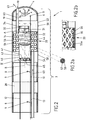
- an elongated medical device 1 is formed as an ablation catheter, e.g. to be used in the curative treatment of Atrial fibrillation and other hearth rhythm diseases like Atrial Flutter, Accessory Pathways or Ventricular Tachycardia.
- the elongated medical device 1 comprises an elongated body 2, which is only partly shown in Fig. 2 .
- a tip electrode 6 arranged at its distal end 4.
- two annular electrodes 8 are arranged at the distal portion 3 of the elongated body 2 and are separated to each other by intermediate isolation elements 28.
- a proximal portion 5 of the elongated body 2 is formed as a flexible tube and may be made of silicone rubber or ChronePreneTM.
- the distal portion houses towards its distal end 4 at least a part of an optical force sensing assembly 20, which is shown in more detail in Fig. 2-6 .
- the force sensing assembly 20 comprises a light source 30 mounted on a light source mounting 53 of a mounting assembly 50 and an optical sensor 40 mounted on an optical sensor mounting 54 of the mounting assembly 50.
- the mounting assembly 50 further comprising an elastic element 51, which is formed as a helical spring that has a metal core 57 and an outer rim 58, which is formed by an isolating plastic tube.
- Fig. 2b shows an alternative embodiment of the elastic element, which is formed in this alternative embodiment as an elastic tube 55, which is e.g. made out of Neoprene or ChronoPreneTM.
- the cylindrical wall of this elastic tube 55 may be perforated with openings 55a, which may have a round, oval, or rhomboid shape, as shown in Fig. 2b .
- the light source mounting 53 and the optical sensor mounting 54 have an outer diameter, which is within tolerance, almost the same as the outer diameter of the electrodes 8, the intermediate isolation elements 28, the flexible tube 56, the tip electrode 6 and the proximal portion 5 of the elongated body 2.
- the light source mounting 53 and the optical sensor mounting 54 may also function as isolation elements, electrically isolating the tip electrode 6 from the next electrode 8 and also from the optical sensor 40 and the light source 30.
- the light source 30 comprises an LED 31 that is mounted on a circuit board 34.
- the LED 31 functions as a point light source, but it has to be mentioned that other point light sources may be used as well.
- the LED 31 has a size of e.g. 0.25 mm (width or diameter) in this embodiment, but generally it may have a size smaller than 1 mm.
- the LED body may have a size of around 1 xO.5x0.4 mm or smaller.
- the light source 30 cooperates with a diffusor 32, which is mounted on the light source 30, coaxially to an optical light source axis A, which is defined by the light source 30, especially by the LED 31.
- the optical sensor 40 defines an optical sensor axis B, which is in the initial state of the elongated medical device 1 coaxially with the optical light source axis A.
- the optical sensor 40 is formed as a camera module, especially as a wafer-level camera, and comprises a pixel array 41 with a number of n pixels 42 (see Fig. 7 to 12 ) that are arranged on a circuit board 45.
- Wafer-level camera also comprises an optical element 44, like a lens, that is coaxially with the optical sensor axis B.
- Wafer-level camera (camera module or optical sensor 40) has a view angle ⁇ in air between 60 and 1 80 degrees, especially between 90 and 120 degrees.
- Optical sensor 40 further comprises a housing 46 that houses on the one end the circuit board 45 with the pixel array 41 and on its other end along the optical sensor axis B the optic element 44.
- the optic element 44 is a lens with F 6.0 and 90 degree wide angle.
- the optical sensor 40 is connected via a line 12 with a data processing and control unit 15 (see Fig. 1 ), which energizes and controls the optical sensor 40 and which also processes sensor data received from the optical sensor 40 and outputs these force sensor data via a data output unit 1 6.
- Data processing and control unit 1 5 is also connected with the electrodes 8 and 6 via a line 10 through which it controls and energizes the electrodes 8 and 6.
- the data processing and control unit 1 5 is also connected to the light source 30, which is controlled and energized by the data processing and control unit 15 as well.
- Line 10 is electrically connected to the electrodes 8 and the tip electrode 6 by means of contact points 9.
- Line 10 and line 12 may be combined in a single ribbon cable, flat conductor, flat flexible cable or the like.
- the tip electrode 6 is used for electro ablation of circular excitation patterns (rotors, e.g. in the left atrium of the heart)
- the electrodes 8 are used for mapping and localization purposes of the catheter/the elongated medical device 1.
- the elongated medical device 1 further comprises a fluid supply line 1 3, which may be connected to a fluid supply 1 7 (see Fig. 1 ).
- This fluid supply line 1 3 is hydraulically connected to a hollow spring element 14, which is located radially inwardly of the elastic element 51 and which is hydraulically connected at its second end to a distal fluid supply line 1 9.
- Distal fluid supply line 1 9 is connected to at least one fluid opening 18, through which an irrigation fluid, like e.g. a saline fluid, may flow to the outside of the distal portion 3 of the elongated medical device 1 to irrigate a surrounding portion of the vessel, organ or other body cavity into which the elongated medical device 1 has been introduced.
- Fluid flow 63 through the fluid supply line 1 3, the hollow spring element 14, the distal fluid supply line 1 9 and through the fluid opening 1 8 to the outside of the elongated medical device 1 is indicated by arrows 63 in Fig. 2 .
- the parts in the area of the optical sensor 40 and the light source 30 are made of or covered with black color to absorb any light which is not directly directed from the light source 30 to the optical sensor 40.
- the distal end 4, respectively the tip electrode 6 at the distal portion 3, may experience a force F (see Fig. 3 and 4 ) in any of the directions X, Y, Z of a Cartesian coordinate system or any combination thereof when contacting an inner wall of a vessel, an organ or other body cavity.
- Force F may especially be exerted on the distal end 4, when the tip electrode is pressed against the wall at a vessel, an organ or other body cavity to be treated by an ablation procedure, e.g. an electroablation procedure.
- the light originating from the light source 30 and the LED 31 is falling into the wafer-level camera (optical sensor 40) and covers an illuminated contiguous array of pixels 43 as can be seen in Fig. 7 .
- a center C of this illuminated contiguous array of pixels 43 is coaxially with the optical sensor axis B and coaxially with the optical light source axis A (see Fig. 5, 6 and 7 ).
- the size of the illuminated contiguous array of pixels 43 in the state of the elongated medical device 1, when there is no force applied to the distal end of the elongated body 2 will be about a 1/10 of the total number of pixels. I.e. for a pixel array 41 of the size of 65,000 pixels an illuminated contiguous array of pixels 43 of 6,250 pixels. In other embodiments, the size of the illuminated contiguous array of pixels 43 may be somewhere between 1/3 and 1/30 of the total number of pixels of the pixel array 41.
- an information about the size of the illuminated contiguous array of pixels 43 will be communicated via data line 12 from the wafer-level camera (optical sensor 40) to the data processing and control unit 1 5, which will indicate force data measured to a user via the data output unit 1 6.
- FIG. 3 , 6 and 8 another state of the elongated medical device 1 is shown where a force F is applied in direction Z, respectively in direction of the optical sensor axis B and the optical light source axis A on the distal end 4 of the distal portion 3.
- the force F applied in this example is 1 N.
- Such force may be applied to the distal end 4 of the elongated medical device 1 when the distal end contacts a wall 70 of a vessel, organ or other body cavity to be treated or explored as indicated in Fig. 3 .
- the optical sensor 40 now detects an illuminated contiguous array of pixels 43, which is enlarged in its size, characterized by its radius compared to the size of the illuminated contiguous array of pixels 43 (radius i 0 ) in the initial state of the elongated medical device 1 when there was no force applied to the distal end of the elongated medical device 1. See Fig. 5 and 7 for comparison.
- the size of the illuminated contiguous array of pixels 43 has been enlarged from its initial size, characterized by the radius i 0 (see Fig. 5 and 7 ) of the illuminated contiguous array of pixels 43 to a radius i 1 (see Fig. 6 and 8 ), which is double the size of the initial radius i 0 (for a force of 1 N).
- the center C of the illuminated contiguous array of pixels 43 is still coaxial with the optical sensor axis B and the optical light source axis A, as can be seen especially in Fig. 6 .
- the optical sensor data that are delivered from the optical sensor 40 to the data processing and control unit 15 are image data that describe the size of the illuminated contiguous array of pixels 43.
- i 1 is a measure of the size/radius of the illuminated contiguous pixel array 43 that is receiving light from the light source 30 in the position of the light source 30 in respect to the optical sensor 40 when the force F is applied to the distal end 4 of the elongated body 2 (see Fig. 6 and 8 ).
- the force F will be output on the data output unit 16 to be recognized by the operator.
- the force F will be calculated based on this formula, and the result of 1 N will be presented on the data output unit 16. If the measured ratio of W is e.g. 0.751 88 and d 0 is e.g. 0.5 mm and k is e.g. 4 N/mm then the force applied to the tip is 0.5 N. If, for example, the ratio of i 0 /i 1 is e.g. 0.95 and d0 is e.g. 0.5 mm and k is e.g. 4 N/mm then the force F is 0.1 N, just to give some examples.
- a force F is applied to a side of the distal end 4 of the distal portion 3 due to a contact with an inside wall 70 of a vessel, organ or other body cavity as can be seen in Fig. 4 .
- Force F in Fig. 4 is applied in direction Y and results in a distortion of the distal portion 3 of the elongated body including a distortion of the helical spring (elastic element 51) of the mounting assembly 50 and of the hollow spring element 14.
- This distortion results in a shifting of the illuminated contiguous array of pixels 43 with its center C away from the optical center of the pixel array 41 indicated by the optical axis B as shown in Fig. 12 .
- the optical axis B and the center C of the illuminated contiguous array of pixels 43 are non-coaxial and lie in a distance to each other, indicating the sidewards distortion of the distal end 4/distal portion 3 of the elongated body 2.
- Measurement data from the optical sensor 40 will again be communicated via line 12 to the data processing and control unit 16, which will calculate the force F that is exerted on the distal end 4 of the elongated body 2. Force data will then be displayed/outputted by the data output unit 1 6 for the attention of an operator of the elongated medical device 1.
- Fig. 11 the effect of a sideward distortion of the distal end 4 of the elongated body 2 in the direction opposite to the direction of Fig. 12 is displayed.
- the illuminated contiguous array of pixels 43 and its center C will move away from the optical axis B in the direction opposite to the one displayed in Fig. 12 .
- Figs. 9 and 10 the effect of forces applied to the distal end 4 of the elongated body 2 in directions perpendicular to the ones displayed in Figs. 11 and 12 and to the ones shown in Fig. 8 are shown.
- any combination of sideward distortions and/or axially exerted forces in that direction may occur and being sensed by the optical force sensing assembly 20.
- Fig. 13 a further embodiment of the elongated medical device 1 is shown.
- reference numerals not described in the following text reference is made to the description of Figs. 1 to 12 which is herewith incorporated by reference.
- Fig. 13 differs from the one described in Figs. 1 to 12 in that the light source 30 does not cooperate with a diffusor element 32 but does cooperate with a light guide 33 which is attached to the surface of the light source 30 and which is in a coaxial orientation with the optical light source axis A.
- the optical force sensing assembly 20 will behave in a similar way as described for Figs. 1 to 12 .
- the description for these figures in this respect is herewith incorporated by reference also for the embodiment of Fig. 13 .
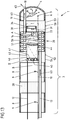
- a further embodiment of the elongated medical device 1 is shown.
- the elastic element 52 is formed by the sidewall 7 of the tip electrode 6, which means that the elastic element 52 and the tip electrode 6 are formed in one single piece.
- the light source cooperates with a diffusor 32.
- the light source may again cooperate with a light guide 33 as displayed in Fig. 13 .
- the helical spring/elastic element 52 cooperates with a tube 29 which may be formed out of a rubber material, e.g. made of neoprene.
- This tube is arranged radially inwardly of the elastic element 52 and is sealingly connected to the optical sensor mounting 54.
- the tube 29 is glued on the inner side of the elastic element 52 and follows every move of this elastic element 52.
- the fluid supply line 13 opens into a chamber 27 defined by this tube 29 and the tip electrode 6.
- the tip electrode 6 in this embodiment has a pattern of fluid openings 18 distributed on the sidewall and its distal end. These fluid openings 18 communicate with this chamber 27 defined by tube 29 and when an irrigation fluid is transported through fluid supply line 13 into the chamber 27, water will flow through the fluid openings 18 to the surrounding area.
- the light source 30 as well as the optical sensor 40 are fluid tightly sealed so that no irrigation fluid may enter any of these electronic/optic components.
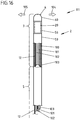
- a further embodiment of an elongated medical device is shown.
- the elongated medical device 111 is formed as a guide wire, which is e.g. used to guide a catheter, such as an ablation catheter, through a vessel, organ or other body cavity.
- the elongated medical device 11 comprises an elongated body 2, which is only partly shown in Fig. 16 .
- an optical force sensing assembly 20 is arranged close to the distal end 4 of the distal portion 3.
- the optical force sensing assembly 20 is similar to the one shown and described e.g. in Fig. 5 and 6 as well as in Fig. 2 to 4 or the one shown and described in Fig. 13 or 15 .
- the part of the elongated medical device 111 which includes the optical sensor mounting, comprises a flexible tube 56, which is e.g. made out of a flexible silicone and which is arranged radially outwardly of the optical force sensing assembly 20.
- the flexible tube 56 seals the area of the optical force sensing assembly 20 against any fluids such as e.g. blood.
- the distal end 4 of the elongated medical device 111 has a tip 60, which may be made out of metal, e.g. stainless steel, platinum, iridium, titanium or nitinol, and which is sealingly connected to the tube 56.
- Tip 60 is attached to the optical force sensing assembly 20 in a way that any force applied to the tip 60 will be sensed by the optical force sensing assembly 20.
- a portion which includes a helical spring element 100 which is radially outwardly surrounded by a flexible tube 59, which may again be e.g. made out of an elastic silicone material.
- a first wire element 101 and a second wire element 1 02 which are both used to steer the elongated medical device 111 in a way that if e.g. wire element 101 is pulled in direction away from the distal end 4, the distal portion 3 of the elongated medical device 111 will bend in a direction 104 while if the second wire element 102 is pulled in a direction away from the distal end 4, the distal portion 3 of the elongated medical device 111 will bend in a direction 105, which is opposite to direction 104.
- the elongated medical device 111 may be steered through vessels, organs or other body cavities. As the body of the elongated medical device 111 may also be rotated, the elongated medical device 111 may be directed/steered into any direction.
- a supply and data line 12 is guided through the helical spring element 1 00 as well as through the proximal portion 5 of the elongated medical device 111 and may be connected to a control and supply unit 15 as well as to an output unit 1 6, which have been shown in Fig. 1 .
- a guide tube 103 Within the proximal portion 5 of the elongated medical device, there is arranged a guide tube 103 through which the wire elements 101 and 102 are guided.
Landscapes
- Health & Medical Sciences (AREA)
- Life Sciences & Earth Sciences (AREA)
- Surgery (AREA)
- Engineering & Computer Science (AREA)
- General Health & Medical Sciences (AREA)
- Veterinary Medicine (AREA)
- Biomedical Technology (AREA)
- Heart & Thoracic Surgery (AREA)
- Medical Informatics (AREA)
- Molecular Biology (AREA)
- Public Health (AREA)
- Animal Behavior & Ethology (AREA)
- Physics & Mathematics (AREA)
- Pathology (AREA)
- Nuclear Medicine, Radiotherapy & Molecular Imaging (AREA)
- Biophysics (AREA)
- Oral & Maxillofacial Surgery (AREA)
- General Physics & Mathematics (AREA)
- Cardiology (AREA)
- Plasma & Fusion (AREA)
- Otolaryngology (AREA)
- Media Introduction/Drainage Providing Device (AREA)
Claims (19)
- Medizinische optische Krafterfassungsbaugruppe (20), die Folgendes umfasst:eine Lichtquelle (30), die eine geradlinige Achse (A) der optischen Lichtquelle definiert,einen optischen Sensor (40), der der Lichtquelle (30) zugewandt ist und eine geradlinige Achse (B) des optischen Sensors definiert, wobei der optische Sensor (40) in einem Abstand (d0, d1) von der Lichtquelle entlang der Achse (B) des optischen Sensors angeordnet ist,eine Befestigungsbaugruppe (50) für den optischen Sensor (40) und die Lichtquelle (30), die eine relative Bewegung der Lichtquelle (30) in Bezug auf den optischen Sensor (40) zumindest in den Richtungen X, Y, Z eines kartesischen Koordinatensystems ermöglicht,wobei die Richtung Z zumindest in einem Ausgangszustand der optischen Krafterfassungsbaugruppe (20) zur Richtung der Achse (B) des optischen Sensors parallel ist und wobei die Richtungen X und Y zueinander senkrecht sowie zur Z-Richtung senkrecht sind;dadurch gekennzeichnet, dassder optische Sensor (40) ein Kameramodul ist, das eine Pixelanordnung (41) von n Pixeln (42) aufweist, wobei im Gebrauch eine zusammenhängende Pixelanordnung (43) Licht von der Lichtquelle (30) empfängt, wobei die Größe der beleuchteten, zusammenhängenden Pixelanordnung (43) und die Anzahl der beleuchteten Pixel in der zusammenhängenden Pixelanordnung (43) zu einer Kraft (F), die in der Z-Richtung entweder auf die Lichtquellenbefestigung (53) oder die Befestigung der optischen Quelle (54) wirkt, proportional sind.
- Medizinische optische Krafterfassungsbaugruppe (20) nach Anspruch 1,
dadurch gekennzeichnet, dass
eine Abweichung der Form der beleuchteten, zusammenhängenden Pixelanordnung (43) ein Maß für einen Kraftvektor (F) ist, der in der X-Richtung und/oder in der Y-Richtung oder in einer beliebigen Kombination davon ausgeübt wird. - Medizinische optische Krafterfassungsbaugruppe (20) nach Anspruch 1 oder 2,
dadurch gekennzeichnet, dass
der Abstand (d0) eine maximale Länge von 10 mm, vorzugsweise 1 mm, nochmals stärker bevorzugt 0,5 mm, aufweist. - Medizinische optische Krafterfassungsbaugruppe (20) nach einem der Ansprüche 1 bis 3,
dadurch gekennzeichnet, dass
der optische Sensor (40) eine Kamera auf Wafer-Niveau ist. - Medizinische optische Krafterfassungsbaugruppe (20) nach einem der Ansprüche 1 bis 4,
dadurch gekennzeichnet, dass
das Kameramodul eine Breite kleiner als 1,5 mm x 1,5 mm und/oder einen Durchmesser kleiner als 1,5 mm hat, wobei die Breite und der Durchmesser jeweils in einer Richtung orientiert sind, die zur Achse (B) des optischen Sensors senkrecht ist. - Medizinische optische Krafterfassungsbaugruppe (20) nach einem der Ansprüche 1 bis 5,
dadurch gekennzeichnet, dass
das Kameramodul einen Bildwinkel α in Luft im Bereich von 60 bis 180 Grad, vorzugsweise im Bereich von 90 bis 120 Grad, aufweist. - Medizinische optische Krafterfassungsbaugruppe (20) nach einem der Ansprüche 1 bis 6,
dadurch gekennzeichnet, dass
die Lichtquelle (30) ein Punktlichtquelle ist, die vorzugsweise eine LED (31) umfasst. - Medizinische optische Krafterfassungsbaugruppe (20) nach einem der Ansprüche 1 bis 7,
dadurch gekennzeichnet, dass
die Lichtquelle (30) mit einem Diffusor (32) optisch zusammenwirkt. - Medizinische optische Krafterfassungsbaugruppe (20) nach einem der Ansprüche 1 bis 7,
dadurch gekennzeichnet, dass
die Lichtquelle (30) mit einem Lichteiter (33) optisch zusammenwirkt, wobei der Lichtleiter (33) vorzugsweise als eine Lichtleitfaser ausgebildet ist. - Medizinische optische Krafterfassungsbaugruppe (20) nach einem der Ansprüche 1 bis 9,
dadurch gekennzeichnet, dass
die Befestigungsbaugruppe (50) eine Lichtquellenbefestigung (53), die die Lichtquelle (30) befestigt, 'eine Befestigung (54) des optischen Sensors, die den optischen Sensor (40) befestigt, und ein elastisches Element (51, 52, 55), das die Lichtquellenbefestigung (53) und die Befestigung (54) des optischen Sensors auf bewegliche Weise verbindet, umfasst, wobei das elastische Element (51, 52) vorzugsweise als eine Schraubenfeder oder als ein elastischer Schlauch ausgebildet ist und das elastische Element (51, 55) vorzugsweise zumindest teilweise aus einem gummiartigen Material hergestellt ist. - Medizinische optische Krafterfassungsbaugruppe (20) nach einem der Ansprüche 1 bis 10,
dadurch gekennzeichnet, dass
die Befestigungsbaugruppe (50) ausgelegt ist, die Lichtquellenbefestigung mit der Befestigung (54) des optischen Sensors derart beweglich zu verbinden, dass die optische Achse (A) der Lichtquelle und die optische Achse (B) des Sensors immer parallel zueinander verlaufen. - Medizinische optische Krafterfassungsbaugruppe (20) nach einem der Ansprüche 1 bis 11,
dadurch gekennzeichnet, dass
die Kraft (F), die auf das distale Ende i in der Z-Richtung ausgeübt wird, durch die folgende Formel berechnet werden kann: wobei k die Federkonstante in N/mm ist,d0 der Abstand in mm des optischen Sensors (40) zur Lichtquelle (40) bei der Ausgangsposition der Lichtquelle (30) in Bezug auf den optischen Sensor (40), wenn auf das distale Ende (4) des länglichen Körpers keine Kraft ausgeübt wird, ist,i0 ein Maß für die Größe der beleuchteten, zusammenhängenden Pixelanordnung (43), die Licht von der Lichtquelle (30) empfängt, bei der Ausgangsposition der Lichtquelle (40) in Bezug auf den optischen Sensor (40), wenn auf das distale Ende (4) des länglichen Körpers (2) keine Kraft ausgeübt wird, ist, undi1 ein Maß für die Größe der beleuchteten, zusammenhängenden Pixelanordnung (43), die Licht von der Lichtquelle (30) empfängt, bei einer Position der Lichtquelle (30) in Bezug auf den optischen Sensor (40), wenn die Kraft (F) auf das distale Ende (4) des länglichen Körpers (2) ausgeübt wird, ist.
 - Medizinische optische Krafterfassungsbaugruppe (20) nach einem der Ansprüche 1 bis 12,
dadurch gekennzeichnet, dass
im Gebrauch eine Mitte (C) der beleuchteten, zusammenhängenden Pixelanordnung (43) zur Achse (B) des optischen Sensors koaxial ist, wenn in der X-Richtung oder in der Y-Richtung keine Kraft auf das distale Ende (2) ausgeübt wird, und dass im Gebrauch die Mitte (C) der beleuchteten, zusammenhängenden Pixelanordnung (43) zur Achse (B) des optischen Sensors nicht koaxial ist, wenn in der X-Richtung oder der Y-Richtung eine Kraft (F) auf das distale Ende ausgeübt wird. - Längliche medizinische Einrichtung (1), die zur intravaskulären Einführung geeignet ist, wobei die Einrichtung Folgendes umfasst:einen flexiblen, länglichen Körper (2), der einen distalen Abschnitt (3) mit einem distalen Ende (4) und einen proximalen Abschnitt (5) aufweist, undeine optische Krafterfassungsbaugruppe (20), die in dem flexiblen, länglichen Körper (2) in räumlicher Nähe zum distalen Ende angeordnet ist,dadurch gekennzeichnet, dassdie Krafterfassungsbaugruppe eine medizinische optische Krafterfassungsbaugruppe nach einem der Ansprüche 1 bis 13 ist.
- Medizinische Einrichtung (1) nach Anspruch 14,
dadurch gekennzeichnet, dass
sie eine Datenverarbeitungs- und Steuereinheit (15) umfasst, die ausgelegt ist, Krafterfassungsdaten zu verarbeiten, die über eine Datenleitung (12) vom optischen Sensor (40) geliefert werden, und mittels einer Datenausgabeeinheit (16) Kraftdaten auszugeben. - Medizinische Einrichtung (1) nach einem der Ansprüche 14 und 15,
dadurch gekennzeichnet, dass
sie als ein Katheter zur Untersuchung oder Behandlung eines Gefäßes, eines Organs oder eines anderen Körperhohlraums ausgebildet ist. - Medizinische Einrichtung (1) nach einem der Ansprüche 14 bis 16,
dadurch gekennzeichnet, dass
sie als ein Führungsdraht zum Führen eines Katheters oder einer ähnlichen medizinische Vorrichtung durch ein Gefäß, ein Organ oder einen anderen Körperhohlraum ausgebildet ist. - Medizinische Einrichtung (1) nach einem der Ansprüche 14 bis 16,
dadurch gekennzeichnet, dass
sowohl der optische Sensor (40) als auch die Lichtquelle (30) am distalen Abschnitt (3) des länglichen Körpers (2) angeordnet sind. - Medizinische Einrichtung (1) nach einem der Ansprüche 14 bis 16,
dadurch gekennzeichnet, dass
die Lichtquellenbefestigung (53) auf steife Weise mit dem distalen Ende (4) des länglichen Körpers (2) verbunden ist.
Applications Claiming Priority (1)
| Application Number | Priority Date | Filing Date | Title |
|---|---|---|---|
| PCT/EP2015/001097 WO2016192741A1 (en) | 2015-05-29 | 2015-05-29 | Elongated medical device suitable for intravascular insertion, optical force sensing assembly for an elongated medical device and method of making a medical optical force sensing assembly |
Publications (2)
| Publication Number | Publication Date |
|---|---|
| EP3304017A1 EP3304017A1 (de) | 2018-04-11 |
| EP3304017B1 true EP3304017B1 (de) | 2021-10-13 |
Family
ID=53541632
Family Applications (1)
| Application Number | Title | Priority Date | Filing Date |
|---|---|---|---|
| EP15736393.8A Active EP3304017B1 (de) | 2015-05-29 | 2015-05-29 | Längliche medizinische vorrichtung für intravaskuläre insertion und optische kraftsensoranordnung für eine längliche medizinische vorrichtung |
Country Status (3)
| Country | Link |
|---|---|
| US (1) | US10888391B2 (de) |
| EP (1) | EP3304017B1 (de) |
| WO (2) | WO2016192741A1 (de) |
Families Citing this family (6)
| Publication number | Priority date | Publication date | Assignee | Title |
|---|---|---|---|---|
| US11857268B2 (en) * | 2018-05-02 | 2024-01-02 | Koninklijke Philips N.V. | Optical shape sensing device with integrated force sensing region and tip integration |
| JP7339286B2 (ja) * | 2018-06-08 | 2023-09-05 | セント・ジュード・メディカル・インターナショナル・ホールディング・エスエーアールエル | 1つのファイバの力及び形状感知 |
| EP3809980B8 (de) * | 2018-06-22 | 2025-09-03 | Universität Basel | Kraftmessvorrichtung, medizinisches endogerät und verfahren zur verwendung eines solchen endogeräts in vitro |
| US20200152354A1 (en) * | 2018-11-14 | 2020-05-14 | Minnesota Wire | Integrated circuits in cable |
| WO2021205373A1 (en) | 2020-04-08 | 2021-10-14 | Incite Medical Sarl | Catheter distal force sensor |
| CN113520617B (zh) * | 2021-07-21 | 2023-10-20 | 天津大学 | 一种无源式三维力传感测头及光学式力传感器 |
Family Cites Families (14)
| Publication number | Priority date | Publication date | Assignee | Title |
|---|---|---|---|---|
| JP2006003137A (ja) * | 2004-06-16 | 2006-01-05 | Toudai Tlo Ltd | 光学式触覚センサ及び該センサにおける情報取得方法 |
| TW200808360A (en) | 2006-04-13 | 2008-02-16 | Alcon Mfg Ltd | RNAi-mediated inhibition of spleen tyrosine kinase-related inflammatory conditions |
| US8567265B2 (en) * | 2006-06-09 | 2013-10-29 | Endosense, SA | Triaxial fiber optic force sensing catheter |
| US8048063B2 (en) | 2006-06-09 | 2011-11-01 | Endosense Sa | Catheter having tri-axial force sensor |
| US20080051704A1 (en) | 2006-08-28 | 2008-02-28 | Patel Rajnikant V | Catheter and system for using same |
| US20080275367A1 (en) | 2007-04-23 | 2008-11-06 | Hansen Medical, Inc | Systems and methods for mapping intra-body tissue compliance |
| US9855410B2 (en) * | 2007-05-01 | 2018-01-02 | St. Jude Medical, Atrial Fibrillation Division, Inc. | Optic-based contact sensing assembly and system |
| US8529476B2 (en) | 2009-12-28 | 2013-09-10 | Biosense Webster (Israel), Ltd. | Catheter with strain gauge sensor |
| WO2012055024A1 (en) * | 2010-10-26 | 2012-05-03 | Valorbec Societe En Commandite | System for sensing a mechanical property of a sample |
| EP2586363A1 (de) | 2011-10-24 | 2013-05-01 | VascoMed GmbH | Katheter und Katheteranordnung |
| WO2013101923A1 (en) * | 2011-12-29 | 2013-07-04 | St. Jude Medical, Atrial Fibrillation Division, Inc. | System for optimized coupling of ablation catheters to body tissues and evaluation of lesions formed by the catheters |
| ES2556810T3 (es) * | 2012-02-07 | 2016-01-20 | Sensoptic Sa | Elemento óptico sensor de fuerza e instrumento microquirúrgico |
| US9372126B2 (en) * | 2013-01-29 | 2016-06-21 | St. Jude Medical, Atrial Fibrillation Division, Inc. | Low-complexity optical force sensor for a medical device |
| TWI567957B (zh) * | 2014-05-30 | 2017-01-21 | 榮晶生物科技股份有限公司 | 晶圓級相機模組及其製造方法 |
-
2015
- 2015-05-29 EP EP15736393.8A patent/EP3304017B1/de active Active
- 2015-05-29 US US15/577,924 patent/US10888391B2/en active Active
- 2015-05-29 WO PCT/EP2015/001097 patent/WO2016192741A1/en not_active Ceased
-
2016
- 2016-05-25 WO PCT/EP2016/000870 patent/WO2016192841A1/en not_active Ceased
Also Published As
| Publication number | Publication date |
|---|---|
| WO2016192741A1 (en) | 2016-12-08 |
| EP3304017A1 (de) | 2018-04-11 |
| US10888391B2 (en) | 2021-01-12 |
| WO2016192841A1 (en) | 2016-12-08 |
| US20180161119A1 (en) | 2018-06-14 |
Similar Documents
| Publication | Publication Date | Title |
|---|---|---|
| US10888391B2 (en) | Optical force sensing assembly for an elongated medical device | |
| JP6814315B2 (ja) | 光学的感知のためのマルチ・コア・ファイバを有する医療デバイス | |
| US20240415572A1 (en) | One fiber force and shape sensing | |
| US8864757B2 (en) | System and method for measuring force and torque applied to a catheter electrode tip | |
| EP2814397B1 (de) | System zur prüfung der auswirkungen einer ablationstherapie an herzgewebe mittels photoakustik | |
| EP1892009B1 (de) | Endoskop-Behandlungsinstrument | |
| CN110944591B (zh) | 光学力感测导管系统 | |
| EP2477572B1 (de) | Medizinische ultraschallvorrichtung mit krafterkennung | |
| JP3949730B2 (ja) | 曲げ応答型カテーテル | |
| US20090171331A1 (en) | Systems and methods of photodynamic-based cardiac ablation via the esophagus | |
| CN111065431B (zh) | 利用光纤感应前端压力的导管及导管系统 | |
| WO2017041891A1 (en) | Elongated medical device suitable for intravascular insertion | |
| EP3363355B1 (de) | Elektrophysiologische vorrichtung und verfahren zur konstruktion der elektrophysiologischen vorrichtung | |
| EP3998935B1 (de) | Kabelverwaltungskoppler für eine medizinische vorrichtung | |
| US11707231B2 (en) | Apparatuses, methods, and systems for contact force sensing | |
| US12582463B2 (en) | Ablation catheter tip with flexible electronic circuitry | |
| KR20150026442A (ko) | 다전극 맵핑 폐정맥형 원형 카테터 |
Legal Events
| Date | Code | Title | Description |
|---|---|---|---|
| STAA | Information on the status of an ep patent application or granted ep patent |
Free format text: STATUS: THE INTERNATIONAL PUBLICATION HAS BEEN MADE |
|
| PUAI | Public reference made under article 153(3) epc to a published international application that has entered the european phase |
Free format text: ORIGINAL CODE: 0009012 |
|
| STAA | Information on the status of an ep patent application or granted ep patent |
Free format text: STATUS: REQUEST FOR EXAMINATION WAS MADE |
|
| 17P | Request for examination filed |
Effective date: 20171221 |
|
| AK | Designated contracting states |
Kind code of ref document: A1 Designated state(s): AL AT BE BG CH CY CZ DE DK EE ES FI FR GB GR HR HU IE IS IT LI LT LU LV MC MK MT NL NO PL PT RO RS SE SI SK SM TR |
|
| AX | Request for extension of the european patent |
Extension state: BA ME |
|
| DAV | Request for validation of the european patent (deleted) | ||
| DAX | Request for extension of the european patent (deleted) | ||
| GRAP | Despatch of communication of intention to grant a patent |
Free format text: ORIGINAL CODE: EPIDOSNIGR1 |
|
| STAA | Information on the status of an ep patent application or granted ep patent |
Free format text: STATUS: GRANT OF PATENT IS INTENDED |
|
| INTG | Intention to grant announced |
Effective date: 20210506 |
|
| GRAS | Grant fee paid |
Free format text: ORIGINAL CODE: EPIDOSNIGR3 |
|
| GRAA | (expected) grant |
Free format text: ORIGINAL CODE: 0009210 |
|
| STAA | Information on the status of an ep patent application or granted ep patent |
Free format text: STATUS: THE PATENT HAS BEEN GRANTED |
|
| AK | Designated contracting states |
Kind code of ref document: B1 Designated state(s): AL AT BE BG CH CY CZ DE DK EE ES FI FR GB GR HR HU IE IS IT LI LT LU LV MC MK MT NL NO PL PT RO RS SE SI SK SM TR |
|
| REG | Reference to a national code |
Ref country code: GB Ref legal event code: FG4D |
|
| REG | Reference to a national code |
Ref country code: CH Ref legal event code: EP |
|
| REG | Reference to a national code |
Ref country code: DE Ref legal event code: R096 Ref document number: 602015074089 Country of ref document: DE |
|
| REG | Reference to a national code |
Ref country code: IE Ref legal event code: FG4D |
|
| REG | Reference to a national code |
Ref country code: AT Ref legal event code: REF Ref document number: 1438509 Country of ref document: AT Kind code of ref document: T Effective date: 20211115 |
|
| REG | Reference to a national code |
Ref country code: LT Ref legal event code: MG9D |
|
| REG | Reference to a national code |
Ref country code: NL Ref legal event code: MP Effective date: 20211013 |
|
| REG | Reference to a national code |
Ref country code: AT Ref legal event code: MK05 Ref document number: 1438509 Country of ref document: AT Kind code of ref document: T Effective date: 20211013 |
|
| PG25 | Lapsed in a contracting state [announced via postgrant information from national office to epo] |
Ref country code: RS Free format text: LAPSE BECAUSE OF FAILURE TO SUBMIT A TRANSLATION OF THE DESCRIPTION OR TO PAY THE FEE WITHIN THE PRESCRIBED TIME-LIMIT Effective date: 20211013 Ref country code: LT Free format text: LAPSE BECAUSE OF FAILURE TO SUBMIT A TRANSLATION OF THE DESCRIPTION OR TO PAY THE FEE WITHIN THE PRESCRIBED TIME-LIMIT Effective date: 20211013 Ref country code: FI Free format text: LAPSE BECAUSE OF FAILURE TO SUBMIT A TRANSLATION OF THE DESCRIPTION OR TO PAY THE FEE WITHIN THE PRESCRIBED TIME-LIMIT Effective date: 20211013 Ref country code: BG Free format text: LAPSE BECAUSE OF FAILURE TO SUBMIT A TRANSLATION OF THE DESCRIPTION OR TO PAY THE FEE WITHIN THE PRESCRIBED TIME-LIMIT Effective date: 20220113 Ref country code: AT Free format text: LAPSE BECAUSE OF FAILURE TO SUBMIT A TRANSLATION OF THE DESCRIPTION OR TO PAY THE FEE WITHIN THE PRESCRIBED TIME-LIMIT Effective date: 20211013 |
|
| PG25 | Lapsed in a contracting state [announced via postgrant information from national office to epo] |
Ref country code: IS Free format text: LAPSE BECAUSE OF FAILURE TO SUBMIT A TRANSLATION OF THE DESCRIPTION OR TO PAY THE FEE WITHIN THE PRESCRIBED TIME-LIMIT Effective date: 20220213 Ref country code: SE Free format text: LAPSE BECAUSE OF FAILURE TO SUBMIT A TRANSLATION OF THE DESCRIPTION OR TO PAY THE FEE WITHIN THE PRESCRIBED TIME-LIMIT Effective date: 20211013 Ref country code: PT Free format text: LAPSE BECAUSE OF FAILURE TO SUBMIT A TRANSLATION OF THE DESCRIPTION OR TO PAY THE FEE WITHIN THE PRESCRIBED TIME-LIMIT Effective date: 20220214 Ref country code: PL Free format text: LAPSE BECAUSE OF FAILURE TO SUBMIT A TRANSLATION OF THE DESCRIPTION OR TO PAY THE FEE WITHIN THE PRESCRIBED TIME-LIMIT Effective date: 20211013 Ref country code: NO Free format text: LAPSE BECAUSE OF FAILURE TO SUBMIT A TRANSLATION OF THE DESCRIPTION OR TO PAY THE FEE WITHIN THE PRESCRIBED TIME-LIMIT Effective date: 20220113 Ref country code: NL Free format text: LAPSE BECAUSE OF FAILURE TO SUBMIT A TRANSLATION OF THE DESCRIPTION OR TO PAY THE FEE WITHIN THE PRESCRIBED TIME-LIMIT Effective date: 20211013 Ref country code: LV Free format text: LAPSE BECAUSE OF FAILURE TO SUBMIT A TRANSLATION OF THE DESCRIPTION OR TO PAY THE FEE WITHIN THE PRESCRIBED TIME-LIMIT Effective date: 20211013 Ref country code: HR Free format text: LAPSE BECAUSE OF FAILURE TO SUBMIT A TRANSLATION OF THE DESCRIPTION OR TO PAY THE FEE WITHIN THE PRESCRIBED TIME-LIMIT Effective date: 20211013 Ref country code: GR Free format text: LAPSE BECAUSE OF FAILURE TO SUBMIT A TRANSLATION OF THE DESCRIPTION OR TO PAY THE FEE WITHIN THE PRESCRIBED TIME-LIMIT Effective date: 20220114 Ref country code: ES Free format text: LAPSE BECAUSE OF FAILURE TO SUBMIT A TRANSLATION OF THE DESCRIPTION OR TO PAY THE FEE WITHIN THE PRESCRIBED TIME-LIMIT Effective date: 20211013 |
|
| REG | Reference to a national code |
Ref country code: DE Ref legal event code: R097 Ref document number: 602015074089 Country of ref document: DE |
|
| PG25 | Lapsed in a contracting state [announced via postgrant information from national office to epo] |
Ref country code: SM Free format text: LAPSE BECAUSE OF FAILURE TO SUBMIT A TRANSLATION OF THE DESCRIPTION OR TO PAY THE FEE WITHIN THE PRESCRIBED TIME-LIMIT Effective date: 20211013 Ref country code: SK Free format text: LAPSE BECAUSE OF FAILURE TO SUBMIT A TRANSLATION OF THE DESCRIPTION OR TO PAY THE FEE WITHIN THE PRESCRIBED TIME-LIMIT Effective date: 20211013 Ref country code: RO Free format text: LAPSE BECAUSE OF FAILURE TO SUBMIT A TRANSLATION OF THE DESCRIPTION OR TO PAY THE FEE WITHIN THE PRESCRIBED TIME-LIMIT Effective date: 20211013 Ref country code: EE Free format text: LAPSE BECAUSE OF FAILURE TO SUBMIT A TRANSLATION OF THE DESCRIPTION OR TO PAY THE FEE WITHIN THE PRESCRIBED TIME-LIMIT Effective date: 20211013 Ref country code: DK Free format text: LAPSE BECAUSE OF FAILURE TO SUBMIT A TRANSLATION OF THE DESCRIPTION OR TO PAY THE FEE WITHIN THE PRESCRIBED TIME-LIMIT Effective date: 20211013 Ref country code: CZ Free format text: LAPSE BECAUSE OF FAILURE TO SUBMIT A TRANSLATION OF THE DESCRIPTION OR TO PAY THE FEE WITHIN THE PRESCRIBED TIME-LIMIT Effective date: 20211013 |
|
| PLBE | No opposition filed within time limit |
Free format text: ORIGINAL CODE: 0009261 |
|
| STAA | Information on the status of an ep patent application or granted ep patent |
Free format text: STATUS: NO OPPOSITION FILED WITHIN TIME LIMIT |
|
| 26N | No opposition filed |
Effective date: 20220714 |
|
| PG25 | Lapsed in a contracting state [announced via postgrant information from national office to epo] |
Ref country code: AL Free format text: LAPSE BECAUSE OF FAILURE TO SUBMIT A TRANSLATION OF THE DESCRIPTION OR TO PAY THE FEE WITHIN THE PRESCRIBED TIME-LIMIT Effective date: 20211013 |
|
| PG25 | Lapsed in a contracting state [announced via postgrant information from national office to epo] |
Ref country code: SI Free format text: LAPSE BECAUSE OF FAILURE TO SUBMIT A TRANSLATION OF THE DESCRIPTION OR TO PAY THE FEE WITHIN THE PRESCRIBED TIME-LIMIT Effective date: 20211013 |
|
| REG | Reference to a national code |
Ref country code: CH Ref legal event code: PL |
|
| REG | Reference to a national code |
Ref country code: BE Ref legal event code: MM Effective date: 20220531 |
|
| GBPC | Gb: european patent ceased through non-payment of renewal fee |
Effective date: 20220529 |
|
| PG25 | Lapsed in a contracting state [announced via postgrant information from national office to epo] |
Ref country code: MC Free format text: LAPSE BECAUSE OF FAILURE TO SUBMIT A TRANSLATION OF THE DESCRIPTION OR TO PAY THE FEE WITHIN THE PRESCRIBED TIME-LIMIT Effective date: 20211013 Ref country code: LU Free format text: LAPSE BECAUSE OF NON-PAYMENT OF DUE FEES Effective date: 20220529 Ref country code: LI Free format text: LAPSE BECAUSE OF NON-PAYMENT OF DUE FEES Effective date: 20220531 Ref country code: CH Free format text: LAPSE BECAUSE OF NON-PAYMENT OF DUE FEES Effective date: 20220531 |
|
| PG25 | Lapsed in a contracting state [announced via postgrant information from national office to epo] |
Ref country code: IE Free format text: LAPSE BECAUSE OF NON-PAYMENT OF DUE FEES Effective date: 20220529 Ref country code: FR Free format text: LAPSE BECAUSE OF NON-PAYMENT OF DUE FEES Effective date: 20220531 |
|
| PG25 | Lapsed in a contracting state [announced via postgrant information from national office to epo] |
Ref country code: IT Free format text: LAPSE BECAUSE OF FAILURE TO SUBMIT A TRANSLATION OF THE DESCRIPTION OR TO PAY THE FEE WITHIN THE PRESCRIBED TIME-LIMIT Effective date: 20211013 Ref country code: GB Free format text: LAPSE BECAUSE OF NON-PAYMENT OF DUE FEES Effective date: 20220529 Ref country code: BE Free format text: LAPSE BECAUSE OF NON-PAYMENT OF DUE FEES Effective date: 20220531 |
|
| P01 | Opt-out of the competence of the unified patent court (upc) registered |
Effective date: 20230522 |
|
| PG25 | Lapsed in a contracting state [announced via postgrant information from national office to epo] |
Ref country code: HU Free format text: LAPSE BECAUSE OF FAILURE TO SUBMIT A TRANSLATION OF THE DESCRIPTION OR TO PAY THE FEE WITHIN THE PRESCRIBED TIME-LIMIT; INVALID AB INITIO Effective date: 20150529 |
|
| PG25 | Lapsed in a contracting state [announced via postgrant information from national office to epo] |
Ref country code: MK Free format text: LAPSE BECAUSE OF FAILURE TO SUBMIT A TRANSLATION OF THE DESCRIPTION OR TO PAY THE FEE WITHIN THE PRESCRIBED TIME-LIMIT Effective date: 20211013 Ref country code: CY Free format text: LAPSE BECAUSE OF FAILURE TO SUBMIT A TRANSLATION OF THE DESCRIPTION OR TO PAY THE FEE WITHIN THE PRESCRIBED TIME-LIMIT Effective date: 20211013 |
|
| REG | Reference to a national code |
Ref country code: DE Ref legal event code: R081 Ref document number: 602015074089 Country of ref document: DE Owner name: CORTEX, INC.., MENLO PARK, US Free format text: FORMER OWNER: ABLACON INC., WHEAT RIDGE, CO, US Ref country code: DE Ref legal event code: R081 Ref document number: 602015074089 Country of ref document: DE Owner name: BOSTON SCIENTIFIC SCIMED, INC., MAPLE GROVE, US Free format text: FORMER OWNER: ABLACON INC., WHEAT RIDGE, CO, US |
|
| PG25 | Lapsed in a contracting state [announced via postgrant information from national office to epo] |
Ref country code: MT Free format text: LAPSE BECAUSE OF FAILURE TO SUBMIT A TRANSLATION OF THE DESCRIPTION OR TO PAY THE FEE WITHIN THE PRESCRIBED TIME-LIMIT Effective date: 20211013 |
|
| PGFP | Annual fee paid to national office [announced via postgrant information from national office to epo] |
Ref country code: DE Payment date: 20250423 Year of fee payment: 11 |
|
| REG | Reference to a national code |
Ref country code: DE Ref legal event code: R082 Ref document number: 602015074089 Country of ref document: DE Representative=s name: BETTEN & RESCH PATENT- UND RECHTSANWAELTE PART, DE Ref country code: DE Ref legal event code: R082 Ref document number: 602015074089 Country of ref document: DE Representative=s name: PFENNING, MEINIG & PARTNER MBB PATENTANWAELTE, DE |
|
| REG | Reference to a national code |
Ref country code: DE Ref legal event code: R082 Ref document number: 602015074089 Country of ref document: DE Representative=s name: BETTEN & RESCH PATENT- UND RECHTSANWAELTE PART, DE Ref country code: DE Ref legal event code: R082 Ref document number: 602015074089 Country of ref document: DE Representative=s name: PFENNING, MEINIG & PARTNER MBB PATENTANWAELTE, DE |
|
| PG25 | Lapsed in a contracting state [announced via postgrant information from national office to epo] |
Ref country code: TR Free format text: LAPSE BECAUSE OF FAILURE TO SUBMIT A TRANSLATION OF THE DESCRIPTION OR TO PAY THE FEE WITHIN THE PRESCRIBED TIME-LIMIT Effective date: 20211013 |
|
| REG | Reference to a national code |
Ref country code: DE Ref legal event code: R081 Ref document number: 602015074089 Country of ref document: DE Owner name: BOSTON SCIENTIFIC SCIMED, INC., MAPLE GROVE, US Free format text: FORMER OWNER: CORTEX, INC.., MENLO PARK, CA, US Ref country code: DE Ref legal event code: R082 Ref document number: 602015074089 Country of ref document: DE Representative=s name: PFENNING, MEINIG & PARTNER MBB PATENTANWAELTE, DE |