EP3303843B1 - Automotive vacuum pump - Google Patents
Automotive vacuum pump Download PDFInfo
- Publication number
- EP3303843B1 EP3303843B1 EP15727378.0A EP15727378A EP3303843B1 EP 3303843 B1 EP3303843 B1 EP 3303843B1 EP 15727378 A EP15727378 A EP 15727378A EP 3303843 B1 EP3303843 B1 EP 3303843B1
- Authority
- EP
- European Patent Office
- Prior art keywords
- outlet opening
- pump
- oil outlet
- rotor body
- vacuum pump
- Prior art date
- Legal status (The legal status is an assumption and is not a legal conclusion. Google has not performed a legal analysis and makes no representation as to the accuracy of the status listed.)
- Active
Links
Images

Classifications
-
- F—MECHANICAL ENGINEERING; LIGHTING; HEATING; WEAPONS; BLASTING
- F04—POSITIVE - DISPLACEMENT MACHINES FOR LIQUIDS; PUMPS FOR LIQUIDS OR ELASTIC FLUIDS
- F04C—ROTARY-PISTON, OR OSCILLATING-PISTON, POSITIVE-DISPLACEMENT MACHINES FOR LIQUIDS; ROTARY-PISTON, OR OSCILLATING-PISTON, POSITIVE-DISPLACEMENT PUMPS
- F04C29/00—Component parts, details or accessories of pumps or pumping installations, not provided for in groups F04C18/00 - F04C28/00
- F04C29/02—Lubrication; Lubricant separation
- F04C29/028—Means for improving or restricting lubricant flow
-
- F—MECHANICAL ENGINEERING; LIGHTING; HEATING; WEAPONS; BLASTING
- F04—POSITIVE - DISPLACEMENT MACHINES FOR LIQUIDS; PUMPS FOR LIQUIDS OR ELASTIC FLUIDS
- F04C—ROTARY-PISTON, OR OSCILLATING-PISTON, POSITIVE-DISPLACEMENT MACHINES FOR LIQUIDS; ROTARY-PISTON, OR OSCILLATING-PISTON, POSITIVE-DISPLACEMENT PUMPS
- F04C18/00—Rotary-piston pumps specially adapted for elastic fluids
- F04C18/30—Rotary-piston pumps specially adapted for elastic fluids having the characteristics covered by two or more of groups F04C18/02, F04C18/08, F04C18/22, F04C18/24, F04C18/48, or having the characteristics covered by one of these groups together with some other type of movement between co-operating members
- F04C18/34—Rotary-piston pumps specially adapted for elastic fluids having the characteristics covered by two or more of groups F04C18/02, F04C18/08, F04C18/22, F04C18/24, F04C18/48, or having the characteristics covered by one of these groups together with some other type of movement between co-operating members having the movement defined in group F04C18/08 or F04C18/22 and relative reciprocation between the co-operating members
- F04C18/344—Rotary-piston pumps specially adapted for elastic fluids having the characteristics covered by two or more of groups F04C18/02, F04C18/08, F04C18/22, F04C18/24, F04C18/48, or having the characteristics covered by one of these groups together with some other type of movement between co-operating members having the movement defined in group F04C18/08 or F04C18/22 and relative reciprocation between the co-operating members with vanes reciprocating with respect to the inner member
- F04C18/3441—Rotary-piston pumps specially adapted for elastic fluids having the characteristics covered by two or more of groups F04C18/02, F04C18/08, F04C18/22, F04C18/24, F04C18/48, or having the characteristics covered by one of these groups together with some other type of movement between co-operating members having the movement defined in group F04C18/08 or F04C18/22 and relative reciprocation between the co-operating members with vanes reciprocating with respect to the inner member the inner and outer member being in contact along one line or continuous surface substantially parallel to the axis of rotation
-
- F—MECHANICAL ENGINEERING; LIGHTING; HEATING; WEAPONS; BLASTING
- F04—POSITIVE - DISPLACEMENT MACHINES FOR LIQUIDS; PUMPS FOR LIQUIDS OR ELASTIC FLUIDS
- F04C—ROTARY-PISTON, OR OSCILLATING-PISTON, POSITIVE-DISPLACEMENT MACHINES FOR LIQUIDS; ROTARY-PISTON, OR OSCILLATING-PISTON, POSITIVE-DISPLACEMENT PUMPS
- F04C25/00—Adaptations of pumps for special use of pumps for elastic fluids
- F04C25/02—Adaptations of pumps for special use of pumps for elastic fluids for producing high vacuum
-
- F—MECHANICAL ENGINEERING; LIGHTING; HEATING; WEAPONS; BLASTING
- F04—POSITIVE - DISPLACEMENT MACHINES FOR LIQUIDS; PUMPS FOR LIQUIDS OR ELASTIC FLUIDS
- F04C—ROTARY-PISTON, OR OSCILLATING-PISTON, POSITIVE-DISPLACEMENT MACHINES FOR LIQUIDS; ROTARY-PISTON, OR OSCILLATING-PISTON, POSITIVE-DISPLACEMENT PUMPS
- F04C2220/00—Application
- F04C2220/10—Vacuum
-
- F—MECHANICAL ENGINEERING; LIGHTING; HEATING; WEAPONS; BLASTING
- F04—POSITIVE - DISPLACEMENT MACHINES FOR LIQUIDS; PUMPS FOR LIQUIDS OR ELASTIC FLUIDS
- F04C—ROTARY-PISTON, OR OSCILLATING-PISTON, POSITIVE-DISPLACEMENT MACHINES FOR LIQUIDS; ROTARY-PISTON, OR OSCILLATING-PISTON, POSITIVE-DISPLACEMENT PUMPS
- F04C2240/00—Components
- F04C2240/10—Stators
-
- F—MECHANICAL ENGINEERING; LIGHTING; HEATING; WEAPONS; BLASTING
- F04—POSITIVE - DISPLACEMENT MACHINES FOR LIQUIDS; PUMPS FOR LIQUIDS OR ELASTIC FLUIDS
- F04C—ROTARY-PISTON, OR OSCILLATING-PISTON, POSITIVE-DISPLACEMENT MACHINES FOR LIQUIDS; ROTARY-PISTON, OR OSCILLATING-PISTON, POSITIVE-DISPLACEMENT PUMPS
- F04C2240/00—Components
- F04C2240/20—Rotors
Definitions
- the invention is directed to an automotive vacuum pump which is lubricated with oil, and is preferably directed to a mechanical automotive vacuum pump which is mechanically driven by an internal combustion engine.
- An automotive vacuum pump is provided with a housing arrangement which encloses a pumping chamber and rotatably supports a pump rotor with a pump rotor body.
- the pump rotor body can be separated in axial direction into two functional sections, namely a bearing section and a vane section.
- the bearing section the rotor body is radially supported rotatably at the pump housing arrangement.
- the vane section the rotor body is provided with at least one vane slit wherein at least one slidable pump vane is slidably supported.
- the pump vane or the pump vanes separate the pumping chamber into several rotating pumping compartments.
- the housing arrangement is provided with a pumping chamber gas inlet opening through which gas flows into the pumping chamber and with a pumping chamber gas outlet opening through which compressed gas leaves the pumping chamber.
- the gas inlet opening and the gas outlet opening are provided in a pump chamber front end wall which lies in a radial plane perpendicular to the rotational axis of the pump rotor.
- the vacuum pump is supplied with pressurized oil which is used to improve the pneumatic performance and, in case of a mechanical vacuum pump, is also used to lubricate the mechanical coupling of the vacuum pump.
- a particular amount of oil is supplied into the pumping chamber so that not only gas but also oil has to be discharged from the pumping chamber to avoid extensive vibrations and a deformation of the pump vane in the final discharge phase of the respective pumping compartment.
- the oil is discharged together with the gas through one single combined gas and oil outlet opening. It is also known, to provide a separate oil outlet opening in a front end wall of the housing arrangement.
- the separate oil outlet opening is arranged behind the gas outlet opening, seen in the direction of rotation. As a consequence, the oil outlet opening is relatively small so that the flow and pressure conditions during the oil discharge phase can be dramatic, in particular at high rotational speed.
- EP 2 677 118 A1 discloses an automotive vacuum pump with an oil opening provided at the rotor body. The oil discharge path is opened dependent on the rotor position.
- the automotive vacuum pump according to the invention is provided with a rotor body which is provided with a separate oil outlet opening which is open to the pumping chamber and through which the oil is discharged from the rotating pumping compartment in the final compression phase of of the respective pumping compartment.
- the oil outlet opening is not provided in a static housing wall anymore, but is co-rotatably provided at the rotor body.
- the gas outlet opening is preferably arranged at a static side wall of the pump housing arrangement. Therefore, the gas outlet opening and the separate oil outlet opening are not in conflict anymore with respect to the available surface. Since the oil outlet opening is not provided at the housing, the opening angle of the oil outlet opening can be increased significantly.
- the gas openings are in fluidic connection with a pump gas inlet and with a pump gas outlet, respectively. It is not excluded that oil is flowing through a gas opening.
- the oil outlet opening has the main function to lead oil to a separate oil outlet, not to the pump gas outlet. But it can not be excluded that also gas is discharged through the oil outlet opening.
- the oil outlet opening is provided in the longitudinal cylindrical vane section of the rotor body.
- the oil outlet opening is not provided in the bearing section of the rotor body. More preferably, the complete oil outlet opening is provided in the cylindrical vane section of the rotor body.
- the pumping chamber is covered by two front end walls both lying in a radial plane so that the end walls are lying in a plane perpendicular to the rotational axis of the pump rotor.
- the oil outlet opening is provided adjacent to one end wall, and is in particular provided adjacent to the front end wall which is lying below the other end wall, with respect to the vector of gravitation, when the vacuum pump is mounted in an automobile.
- the oil outlet opening is preferably placed as close as possible to the bottom plane of the rotor to minimize the pressure drop all along the rotor's internal duct. More preferably, the oil outlet opening is arranged at the lowest point of the pumping chamber in the final phase of the compression interval of the respective pumping compartment. This arrangement of the oil outlet opening makes sure that the oil volume which is accumulated at the lowest gravitational location within the rotating pumping compartment can directly be discharged via the oil outlet opening when the rotating oil outlet opening arrives at the final compression phase of the respective pumping compartment.
- the opening angle of the oil outlet opening is smaller than the angle of the gas-tight commutation sector between the gas outlet opening and the gas inlet opening so that the oil outlet opening can not define a fluidic bypass with respect to the commutation sector.
- the opening angle of the outlet opening is an angle lying in a radial plane and with the sector center lying in the rotational axis of the pump rotor.
- the oil outlet opening is provided in the lagging third of the respective pumping compartment, and preferably in the lagging fourth of the respective pumping compartment.
- the oil outlet opening arrives at the final compression zone right before the vane head arrives at the commutation sector which is the liquid-tight sector between the gas outlet opening and the gas inlet opening, seen in the direction of rotation.
- the oil outlet opening is arranged in that sector of the respective pumping compartment which arrives at last at the gas-tight commutation sector.
- the pump rotor is provided with a coupling structure at one axial coupling end of the rotor body.
- the coupling structure is provided at one axial coupling end which is defined by the bearing section of the rotor body.
- the rotor body is provided with an oil conduct which fluidically connects the oil outlet opening to the axial coupling end.
- the coupling structure is directly lubricated with the oil which is discharged via the oil outlet opening.
- the oil discharge opening is provided with a check-valve so that a backflow of the oil in direction from the axial coupling structure and back to the oil outlet opening is avoided.
- the vacuum pump is provided as a single-vane pump with one single pump vane which can have two vane parts which are slidable to each other.
- the single vane is supported by the single vane slit which radially penetrates the rotor body.
- At least two oil outlet openings are provided at the rotor body, one oil outlet opening in each pumping compartment.
- the figures show a mechanical automotive vacuum pump 10 which provides an absolute pressure of below 100 mbar for supplying, for example, a pneumatic breaking force device with low pressure.
- the mechanical vacuum pump 10 is mechanically driven by an automotive engine, for example by an internal combustion engine.
- the vacuum pump 10 comprises a static housing arrangement 12 which supports and substantially houses a rotatable pump rotor 14.
- the housing arrangement 12 comprises a complex and pot-shaped housing main body 11 for radially enclosing and rotatably supporting the pump rotor 14 and comprises a separate housing cover lid 13 for axially closing one axial end of the housing arrangement 12.
- the pump rotor 14 comprises a plastic pump rotor body 30 with a substantially cylindrical and stepless outer surface over the entire axial length of the rotor body 30.
- the rotor body 30 is axially provided with two functional partitions, namely the vane section 16 with a vane slit 32 and the bearing section 18 where the rotor body 30 is rotatably supported at the housing body 11 by a frictional bearing.
- the vane slit 32 supports a radially shiftable pump vane 33 which is defined by one single vane body 34 which is co-rotating with the rotor body 30.
- the housing arrangement 12 defined by the housing body 11 and the housing lid 13 encloses a pumping chamber 17 wherein the pump vane 33 is rotating.
- the housing lid 13 defines one axial front end wall 64 and a ring-like portion of the housing body 11 defines the other front end wall 62 of the pumping chamber 17.
- the pump vane 33 separates the pumping chamber 17 into two pumping compartments 171, 172 which rotate when the pump rotor 14 is rotating.
- the rotor body 30 is provided with a cylindrical bearing surface which defines together with a corresponding cylindrical bearing surface of the housing main body 11 a radial friction bearing.
- the rotor 14, in this embodiment, is supported only by one radial bearing so that the rotor body 14 is supported cantilevered.
- the bearing-sided axial coupling end 72 of the rotor 14 is provided with a bearing ring surface which is axially supported by a corresponding axial bearing ring surface defined by the housing main body 11.
- the two bearing ring surfaces together define an axial friction bearing.
- the bearing-sided coupling end 72 of the rotor 14 is provided with a coupling structure 70 for coupling a corresponding coupling structure of a pump driving means.
- the other front end of the rotor body 30 is axially supported by the housing lid 13.
- the bearing-sided front end wall 62 is provided with a sickle-shaped gas inlet opening 26 and with a sickle -shaped gas outlet opening 22.
- the gas inlet opening 26 is fluidically connected to a pump inlet 28 via a gas inlet channel 27.
- the gas outlet channel is fluidically connected to a pump outlet via a gas outlet channel 23.
- the gas inlet channel 27 and the gas outlet channel 23 are defined as bores in a ring body section 20 of the housing body 11.
- a commutation sector 60 is defined between the gas outlet opening 22 and the gas inlet opening 26, see Fig. 1 .
- the rotor body 30 is arranged directly adjacent to the circumferential wall 80 of the housing body 11 so that the commutation sector 60 defines a gas-tight section thereby avoiding a flow-back of compressed gas.
- the commutation width of the commutation sector 60, seen in circumferential direction, is equal or larger than the thickness of the vane body 34 or of the vane slit 32.
- the rotor body 30 is provided with two separate oil outlet openings 40, 40' defined by outlet recesses 41, 41' which are both radially orientated and open to the respective pumping compartment 171, 172.
- the oil outlet openings 40, 40' both respectively lie in a cylindrical plane defined by the cylindrical outer surface of the rotor body 30.
- the pump rotor 14 rotates in clockwise direction so that the oil outlet openings 40, 40' both are arranged in the lagging fourth of the respective rotating pumping compartment 171, 172, so that the respective outlet opening 40, 40' arrives at the commutation sector 60 in the final part of the compression phase of the respective pumping compartment 171, 172.
- the opening angle 66 of the oil outlet openings is slightly smaller than the commutation sector angle of the commutation sector 60 where the cylindrical commutation slit is gas-tight.
- the oil outlet openings 40, 40' are both provided axially adjacent to the ring-like front end wall 62 which is provided with the gas outlet opening 22 and the gas inlet opening 26.
- Figure 2 shows the preferred orientation of the vacuum pump 10 when the vacuum pump 10 is mounted in an automobile.
- the ring -like front end wall 62 is preferably lying below the other front end wall 64 so that oil is collected at the ring -like front end wall 62 because of gravity.
- the oil outlet openings 40, 40' are fluidically connected with corresponding oil discharge openings 44, 44' which are located at the axial coupling end 72 of the rotor body 30.
- the oil outlet opening 40, 40' and the corresponding oil discharge openings 44, 44' are connected by respective oil ducts 42, 42', 43, 43' which are a radial bore duct 42, 42' and an axial bore duct 43, 43'.
- Both discharge openings 44, 44' are provided with a check valve 76, 76', respectively, which comprises a sheet -like valve body 45, 45' and a valve stop 46, 46' which limits the opening movement of the valve body 45, 45'.
- the valve body 45, 45' is defined by a sheet-like flexible tongue and opens the discharge openings 44, 44' when the pressure of the fluid in the respective oil outlet opening 40, 40' is above an opening pressure difference which is, for example, 100 mbar.
- gas in particular air
- the gas is transported in the rotating pumping compartment 172 to the compression side so that the compressed gas is pumped through the gas outlet opening 22 to the pump outlet 24.
- the pump outlet 24 can be provided with a check valve which avoids a flow back of gas into the pumping chamber 17.
Landscapes
- Engineering & Computer Science (AREA)
- Mechanical Engineering (AREA)
- General Engineering & Computer Science (AREA)
- Applications Or Details Of Rotary Compressors (AREA)
- Rotary Pumps (AREA)
Description
- The invention is directed to an automotive vacuum pump which is lubricated with oil, and is preferably directed to a mechanical automotive vacuum pump which is mechanically driven by an internal combustion engine.
- An automotive vacuum pump is provided with a housing arrangement which encloses a pumping chamber and rotatably supports a pump rotor with a pump rotor body. The pump rotor body can be separated in axial direction into two functional sections, namely a bearing section and a vane section. In the bearing section, the rotor body is radially supported rotatably at the pump housing arrangement. In the vane section, the rotor body is provided with at least one vane slit wherein at least one slidable pump vane is slidably supported. The pump vane or the pump vanes separate the pumping chamber into several rotating pumping compartments.
- The housing arrangement is provided with a pumping chamber gas inlet opening through which gas flows into the pumping chamber and with a pumping chamber gas outlet opening through which compressed gas leaves the pumping chamber. The gas inlet opening and the gas outlet opening, in most cases, are provided in a pump chamber front end wall which lies in a radial plane perpendicular to the rotational axis of the pump rotor.
- The vacuum pump is supplied with pressurized oil which is used to improve the pneumatic performance and, in case of a mechanical vacuum pump, is also used to lubricate the mechanical coupling of the vacuum pump. A particular amount of oil is supplied into the pumping chamber so that not only gas but also oil has to be discharged from the pumping chamber to avoid extensive vibrations and a deformation of the pump vane in the final discharge phase of the respective pumping compartment. In state-of-the-art vacuum pumps, the oil is discharged together with the gas through one single combined gas and oil outlet opening. It is also known, to provide a separate oil outlet opening in a front end wall of the housing arrangement. The separate oil outlet opening is arranged behind the gas outlet opening, seen in the direction of rotation. As a consequence, the oil outlet opening is relatively small so that the flow and pressure conditions during the oil discharge phase can be dramatic, in particular at high rotational speed.
-
EP 2 677 118 A1 discloses an automotive vacuum pump with an oil opening provided at the rotor body. The oil discharge path is opened dependent on the rotor position. - It is an object of the invention to provide an automotive vacuum pump with a smoother oil discharge characteristics.
- This object is solved with an automotive vacuum pump with the features of claim 1.
- The automotive vacuum pump according to the invention is provided with a rotor body which is provided with a separate oil outlet opening which is open to the pumping chamber and through which the oil is discharged from the rotating pumping compartment in the final compression phase of of the respective pumping compartment. The oil outlet opening is not provided in a static housing wall anymore, but is co-rotatably provided at the rotor body. The gas outlet opening is preferably arranged at a static side wall of the pump housing arrangement. Therefore, the gas outlet opening and the separate oil outlet opening are not in conflict anymore with respect to the available surface. Since the oil outlet opening is not provided at the housing, the opening angle of the oil outlet opening can be increased significantly. Since the opening angle of the oil outlet opening is increased, there is more time to discharge the oil from the rotating pumping compartment in the final compression phase of the pumping compartment. As a consequence, the oil discharge process is smoother, in particular at high rotational speed of the pump rotor. This leads to decreased noise, decreased vibration and decreased wearout of the mechanical components.
- The gas openings are in fluidic connection with a pump gas inlet and with a pump gas outlet, respectively. It is not excluded that oil is flowing through a gas opening. The oil outlet opening has the main function to lead oil to a separate oil outlet, not to the pump gas outlet. But it can not be excluded that also gas is discharged through the oil outlet opening.
- According to a preferred embodiment, the oil outlet opening is provided in the longitudinal cylindrical vane section of the rotor body. The oil outlet opening is not provided in the bearing section of the rotor body. More preferably, the complete oil outlet opening is provided in the cylindrical vane section of the rotor body.
- Preferably, the pumping chamber is covered by two front end walls both lying in a radial plane so that the end walls are lying in a plane perpendicular to the rotational axis of the pump rotor. The oil outlet opening is provided adjacent to one end wall, and is in particular provided adjacent to the front end wall which is lying below the other end wall, with respect to the vector of gravitation, when the vacuum pump is mounted in an automobile. The oil outlet opening is preferably placed as close as possible to the bottom plane of the rotor to minimize the pressure drop all along the rotor's internal duct. More preferably, the oil outlet opening is arranged at the lowest point of the pumping chamber in the final phase of the compression interval of the respective pumping compartment. This arrangement of the oil outlet opening makes sure that the oil volume which is accumulated at the lowest gravitational location within the rotating pumping compartment can directly be discharged via the oil outlet opening when the rotating oil outlet opening arrives at the final compression phase of the respective pumping compartment.
- The opening angle of the oil outlet opening is smaller than the angle of the gas-tight commutation sector between the gas outlet opening and the gas inlet opening so that the oil outlet opening can not define a fluidic bypass with respect to the commutation sector. The opening angle of the outlet opening is an angle lying in a radial plane and with the sector center lying in the rotational axis of the pump rotor.
- According to a preferred embodiment, the oil outlet opening is provided in the lagging third of the respective pumping compartment, and preferably in the lagging fourth of the respective pumping compartment. As a result, the oil outlet opening arrives at the final compression zone right before the vane head arrives at the commutation sector which is the liquid-tight sector between the gas outlet opening and the gas inlet opening, seen in the direction of rotation. In other words, the oil outlet opening is arranged in that sector of the respective pumping compartment which arrives at last at the gas-tight commutation sector.
- According to a preferred embodiment, the pump rotor is provided with a coupling structure at one axial coupling end of the rotor body. Preferably, the coupling structure is provided at one axial coupling end which is defined by the bearing section of the rotor body. The rotor body is provided with an oil conduct which fluidically connects the oil outlet opening to the axial coupling end. As a result, the coupling structure is directly lubricated with the oil which is discharged via the oil outlet opening.
- Preferably, the oil discharge opening is provided with a check-valve so that a backflow of the oil in direction from the axial coupling structure and back to the oil outlet opening is avoided.
- According to a preferred embodiment, the vacuum pump is provided as a single-vane pump with one single pump vane which can have two vane parts which are slidable to each other. The single vane is supported by the single vane slit which radially penetrates the rotor body. At least two oil outlet openings are provided at the rotor body, one oil outlet opening in each pumping compartment.
- One embodiment of the invention is described referring to the drawings, wherein
-
figure 1 shows a cross-section of a mechanical automotive vacuum pump including a pump rotor with two oil outlet openings, -
figure 2 shows a longitudinal section of the vacuum pump offigure 1 , -
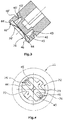
figure 3 shows a longitudinal section of the pump rotor of the vacuum pump offigures 1 and 2 , and -
figure 4 shows a plan view of the bearing section including a coupling structure of the pump rotor of the vacuum pump offigures 1 and 2 . - The figures show a mechanical
automotive vacuum pump 10 which provides an absolute pressure of below 100 mbar for supplying, for example, a pneumatic breaking force device with low pressure. Themechanical vacuum pump 10 is mechanically driven by an automotive engine, for example by an internal combustion engine. - The
vacuum pump 10 comprises astatic housing arrangement 12 which supports and substantially houses arotatable pump rotor 14. Thehousing arrangement 12 comprises a complex and pot-shaped housingmain body 11 for radially enclosing and rotatably supporting thepump rotor 14 and comprises a separatehousing cover lid 13 for axially closing one axial end of thehousing arrangement 12. - The
pump rotor 14 comprises a plasticpump rotor body 30 with a substantially cylindrical and stepless outer surface over the entire axial length of therotor body 30. Therotor body 30 is axially provided with two functional partitions, namely thevane section 16 with avane slit 32 and thebearing section 18 where therotor body 30 is rotatably supported at thehousing body 11 by a frictional bearing. Thevane slit 32 supports a radiallyshiftable pump vane 33 which is defined by onesingle vane body 34 which is co-rotating with therotor body 30. - The
housing arrangement 12 defined by thehousing body 11 and thehousing lid 13 encloses apumping chamber 17 wherein thepump vane 33 is rotating. Thehousing lid 13 defines one axialfront end wall 64 and a ring-like portion of thehousing body 11 defines the otherfront end wall 62 of thepumping chamber 17. Thepump vane 33 separates the pumpingchamber 17 into two pumpingcompartments pump rotor 14 is rotating. - In the
bearing section 18, therotor body 30 is provided with a cylindrical bearing surface which defines together with a corresponding cylindrical bearing surface of the housing main body 11 a radial friction bearing. Therotor 14, in this embodiment, is supported only by one radial bearing so that therotor body 14 is supported cantilevered. The bearing-sidedaxial coupling end 72 of therotor 14 is provided with a bearing ring surface which is axially supported by a corresponding axial bearing ring surface defined by the housingmain body 11. The two bearing ring surfaces together define an axial friction bearing. As shown infigure 4 , the bearing-sided coupling end 72 of therotor 14 is provided with acoupling structure 70 for coupling a corresponding coupling structure of a pump driving means. The other front end of therotor body 30 is axially supported by thehousing lid 13. - The bearing-sided
front end wall 62 is provided with a sickle-shaped gas inlet opening 26 and with a sickle -shapedgas outlet opening 22. The gas inlet opening 26 is fluidically connected to apump inlet 28 via agas inlet channel 27. The gas outlet channel is fluidically connected to a pump outlet via agas outlet channel 23. Thegas inlet channel 27 and thegas outlet channel 23 are defined as bores in aring body section 20 of thehousing body 11. - Seen in circumferential direction, a
commutation sector 60 is defined between the gas outlet opening 22 and the gas inlet opening 26, seeFig. 1 . In thecommutation sector 60, therotor body 30 is arranged directly adjacent to thecircumferential wall 80 of thehousing body 11 so that thecommutation sector 60 defines a gas-tight section thereby avoiding a flow-back of compressed gas. The commutation width of thecommutation sector 60, seen in circumferential direction, is equal or larger than the thickness of thevane body 34 or of the vane slit 32. - The
rotor body 30 is provided with two separateoil outlet openings 40, 40' defined by outlet recesses 41, 41' which are both radially orientated and open to therespective pumping compartment oil outlet openings 40, 40' both respectively lie in a cylindrical plane defined by the cylindrical outer surface of therotor body 30. In the present embodiment, thepump rotor 14 rotates in clockwise direction so that theoil outlet openings 40, 40' both are arranged in the lagging fourth of the respectiverotating pumping compartment commutation sector 60 in the final part of the compression phase of therespective pumping compartment opening angle 66 of the oil outlet openings is slightly smaller than the commutation sector angle of thecommutation sector 60 where the cylindrical commutation slit is gas-tight. Theoil outlet openings 40, 40' are both provided axially adjacent to the ring-likefront end wall 62 which is provided with the gas outlet opening 22 and thegas inlet opening 26.Figure 2 shows the preferred orientation of thevacuum pump 10 when thevacuum pump 10 is mounted in an automobile. The ring -likefront end wall 62 is preferably lying below the otherfront end wall 64 so that oil is collected at the ring -likefront end wall 62 because of gravity. - The
oil outlet openings 40, 40' are fluidically connected with correspondingoil discharge openings 44, 44' which are located at theaxial coupling end 72 of therotor body 30. Theoil outlet opening 40, 40' and the correspondingoil discharge openings 44, 44' are connected byrespective oil ducts radial bore duct 42, 42' and anaxial bore duct 43, 43'. - Both
discharge openings 44, 44' are provided with acheck valve like valve body 45, 45' and avalve stop 46, 46' which limits the opening movement of thevalve body 45, 45'. Thevalve body 45, 45' is defined by a sheet-like flexible tongue and opens thedischarge openings 44, 44' when the pressure of the fluid in the respectiveoil outlet opening 40, 40' is above an opening pressure difference which is, for example, 100 mbar. - When the
pump 10 is in use and therotor 14 is rotating, gas, in particular air, is sucked through thepump inlet 28 and the gas inlet opening 26 into therotating pumping compartment 172 at the suction side. The gas is transported in therotating pumping compartment 172 to the compression side so that the compressed gas is pumped through the gas outlet opening 22 to thepump outlet 24. Thepump outlet 24 can be provided with a check valve which avoids a flow back of gas into the pumpingchamber 17. - During all pumping phases, a limited amount of oil is pumped into the interior of the
pump 10 so that oil is also accumulated within the pumpingchamber 17. The oil in thepumping chamber 17 is in particular accumulated at the bottomfront end wall 62 and is accumulated in the remaining volume of the compression-sided pumping compartment 171 in the final compression phase. As soon as the fluid pressure in thepumping compartment 172 is higher than the atmospheric counter pressure plus the opening pressure difference, thecorresponding check valve 76 opens and the oil is discharged to the area of thecoupling structure 70. - As soon as the
oil outlet opening 40 is completely covered by thecircumferential wall 80 in thecommutation sector 60, thecheck valve 76 closes.
Claims (7)
- An automotive vacuum pump (10) with a housing arrangement (12) enclosing a pumping chamber (17) and rotatably supporting a pump rotor (14) with a rotor body (30) having a bearing section (18) and a vane section (16), wherein
the vane section (16) of the rotor body (30) is provided with a vane slit (32) wherein a slidable pump vane (33) is supported which separates the pumping chamber (17) into several rotating pumping compartments (171, 172),
the housing arrangement (12) is provided with a pumping chamber gas inlet opening (26) and with a pumping chamber gas outlet opening (22),
characterised in that
the rotor body (30) is provided with a separate oil outlet opening (40,40') which is lying in a cylindrical plane defined by the cylindrical outer surface of the rotor body (30) and which is open to the pumping chamber (17), and
the opening angle (66) of the oil outlet opening (40, 40') is smaller than the gas- tight commutation sector (60) defined between the gas outlet opening (22) and the gas inlet opening (26), whereas the opening angle (66) is an angle lying In a radial plane and with the sector center lying in the rotational axis of the pump rotor (14). - The automotive vacuum pump (10) of claim 1, wherein the oil outlet opening (40,40') is provided in the longitudinal cylindrical vane section (16) of the rotor body (30).
- The vacuum pump (10) of one of the preceding claims, wherein the pumping chamber (17) is covered by two front end walls (62, 64) both lying in a radial plane, and wherein the oil outlet opening (40,40') is provided adjacent to one front end wall (62).
- The automotive vacuum pump (10) of one of the preceding claims, wherein the oil outlet opening (40;40') is provided in the lagging third, preferably in the lagging fourth of the respective rotating pumping compartment (171, 172).
- The automotive vacuum pump (10) of one of the preceding claims, wherein the pump rotor (14) is provided with a coupling structure (70) at one axial coupling end (72) of the rotor body (30), and wherein the rotor body (30) is provided with an oil duct (42,43) which fluidically connects the oil outlet opening (40, 40') to the axial coupling end (72).
- The automotive vacuum pump (10) of one of the preceding claims, wherein the axial coupling end (72) is provided with an oil discharge opening (44, 44') which is fluidically connected to the oil outlet opening (40, 40'), and wherein every oil discharge opening (44,44') is provided with a check-valve (76, 76').
- The automotive vacuum pump (10) of one of the preceding claims, wherein one single pump vane (33) with one single vane body (34) is supported in the single vane slit (32) which radially penetrates the rotor body (30), and wherein two oil outlet openings (40; 40') are provided at the rotor body (30), one in each pumping compartment (171, 172).
Applications Claiming Priority (1)
| Application Number | Priority Date | Filing Date | Title |
|---|---|---|---|
| PCT/EP2015/062285 WO2016192782A1 (en) | 2015-06-02 | 2015-06-02 | Automotive vacuum pump |
Publications (2)
| Publication Number | Publication Date |
|---|---|
| EP3303843A1 EP3303843A1 (en) | 2018-04-11 |
| EP3303843B1 true EP3303843B1 (en) | 2020-05-20 |
Family
ID=53298359
Family Applications (1)
| Application Number | Title | Priority Date | Filing Date |
|---|---|---|---|
| EP15727378.0A Active EP3303843B1 (en) | 2015-06-02 | 2015-06-02 | Automotive vacuum pump |
Country Status (4)
| Country | Link |
|---|---|
| US (1) | US20180156218A1 (en) |
| EP (1) | EP3303843B1 (en) |
| CN (1) | CN107636312B (en) |
| WO (1) | WO2016192782A1 (en) |
Family Cites Families (11)
| Publication number | Priority date | Publication date | Assignee | Title |
|---|---|---|---|---|
| US1781073A (en) * | 1928-06-16 | 1930-11-11 | Keystone Refrigerating Corp | Rotary compressor |
| GB1426126A (en) * | 1973-02-16 | 1976-02-25 | Komiya S | Movable vane type compressor |
| JPH08261184A (en) * | 1995-03-24 | 1996-10-08 | Hitachi Ltd | Vane rotary machine |
| JP3389443B2 (en) * | 1997-03-04 | 2003-03-24 | 愛三工業株式会社 | Vane type vacuum pump |
| JP3693469B2 (en) * | 1997-07-15 | 2005-09-07 | 愛三工業株式会社 | Vane type vacuum pump |
| DE102004034926B3 (en) * | 2004-07-09 | 2005-12-29 | Joma-Hydromechanic Gmbh | A single-blade |
| JP3849799B2 (en) * | 2005-02-16 | 2006-11-22 | 大豊工業株式会社 | Vane pump |
| JP5447149B2 (en) * | 2010-04-27 | 2014-03-19 | 大豊工業株式会社 | Vane pump |
| DE102010039343B4 (en) * | 2010-08-16 | 2012-06-14 | Joma-Polytec Gmbh | vacuum pump |
| EP2677118B1 (en) * | 2012-06-20 | 2018-03-28 | Pierburg Pump Technology GmbH | Automotive volumetric vacuum pump |
| CN104481876B (en) * | 2014-12-04 | 2016-08-24 | 宁波圣龙汽车动力系统股份有限公司 | Camshaft integrated form vacuum pump |
-
2015
- 2015-06-02 EP EP15727378.0A patent/EP3303843B1/en active Active
- 2015-06-02 US US15/578,254 patent/US20180156218A1/en not_active Abandoned
- 2015-06-02 WO PCT/EP2015/062285 patent/WO2016192782A1/en not_active Ceased
- 2015-06-02 CN CN201580080100.2A patent/CN107636312B/en not_active Expired - Fee Related
Non-Patent Citations (1)
| Title |
|---|
| None * |
Also Published As
| Publication number | Publication date |
|---|---|
| EP3303843A1 (en) | 2018-04-11 |
| US20180156218A1 (en) | 2018-06-07 |
| CN107636312A (en) | 2018-01-26 |
| CN107636312B (en) | 2019-08-13 |
| WO2016192782A1 (en) | 2016-12-08 |
Similar Documents
| Publication | Publication Date | Title |
|---|---|---|
| CN108397382B (en) | Co-rotating compressor | |
| CN108571447B (en) | Positive displacement machine, operation method thereof, screw, vehicle air conditioning system and vehicle | |
| KR100798055B1 (en) | Gas vane pump, and operation method of the pump | |
| US9759103B2 (en) | Lubricant vane pump | |
| CN105473860B (en) | Convertible lubricant vane pump | |
| EP3076019A1 (en) | Scroll compressor | |
| JP5708570B2 (en) | Vane type compressor | |
| CA2575780C (en) | Single-blade vacuum pump | |
| CN112833008A (en) | Compressor and air conditioner having the same | |
| KR102572044B1 (en) | multistage rotary vane pump | |
| US9175685B2 (en) | Liquid ring pump with gas scavenge device | |
| US20180156218A1 (en) | Automotive vacuum pump | |
| CN109154294B (en) | Dry running vane air pump | |
| CN215409184U (en) | Compressor and air conditioner with same | |
| JP6758424B2 (en) | Compressor | |
| CN106164491A (en) | Rotary vane compressor and method of operating thereof | |
| US20180245592A1 (en) | Lubricated automotive vacuum pump | |
| US11261868B2 (en) | Vane gas pump with sliding element trmporaily completely covering the elongated fluid outlet opening | |
| CN109312749B (en) | Rotary vane compressor and method of operating and manufacturing the same | |
| KR101684549B1 (en) | Rotary vacuum pump | |
| KR101927253B1 (en) | Vane rotary compressor | |
| CN110603381B (en) | Scroll compressor having a discharge port | |
| KR101951199B1 (en) | Vane rotary compressor | |
| KR101697148B1 (en) | Hybrid vane fluid machinery of centrifugal suction type | |
| JP2019056314A (en) | Vane-type compressor |
Legal Events
| Date | Code | Title | Description |
|---|---|---|---|
| STAA | Information on the status of an ep patent application or granted ep patent |
Free format text: STATUS: THE INTERNATIONAL PUBLICATION HAS BEEN MADE |
|
| PUAI | Public reference made under article 153(3) epc to a published international application that has entered the european phase |
Free format text: ORIGINAL CODE: 0009012 |
|
| STAA | Information on the status of an ep patent application or granted ep patent |
Free format text: STATUS: REQUEST FOR EXAMINATION WAS MADE |
|
| 17P | Request for examination filed |
Effective date: 20171107 |
|
| AK | Designated contracting states |
Kind code of ref document: A1 Designated state(s): AL AT BE BG CH CY CZ DE DK EE ES FI FR GB GR HR HU IE IS IT LI LT LU LV MC MK MT NL NO PL PT RO RS SE SI SK SM TR |
|
| AX | Request for extension of the european patent |
Extension state: BA ME |
|
| DAV | Request for validation of the european patent (deleted) | ||
| DAX | Request for extension of the european patent (deleted) | ||
| GRAP | Despatch of communication of intention to grant a patent |
Free format text: ORIGINAL CODE: EPIDOSNIGR1 |
|
| STAA | Information on the status of an ep patent application or granted ep patent |
Free format text: STATUS: GRANT OF PATENT IS INTENDED |
|
| GRAJ | Information related to disapproval of communication of intention to grant by the applicant or resumption of examination proceedings by the epo deleted |
Free format text: ORIGINAL CODE: EPIDOSDIGR1 |
|
| INTG | Intention to grant announced |
Effective date: 20190128 |
|
| INTG | Intention to grant announced |
Effective date: 20190128 |
|
| GRAJ | Information related to disapproval of communication of intention to grant by the applicant or resumption of examination proceedings by the epo deleted |
Free format text: ORIGINAL CODE: EPIDOSDIGR1 |
|
| GRAJ | Information related to disapproval of communication of intention to grant by the applicant or resumption of examination proceedings by the epo deleted |
Free format text: ORIGINAL CODE: EPIDOSDIGR1 |
|
| STAA | Information on the status of an ep patent application or granted ep patent |
Free format text: STATUS: REQUEST FOR EXAMINATION WAS MADE |
|
| INTG | Intention to grant announced |
Effective date: 20190128 |
|
| INTC | Intention to grant announced (deleted) | ||
| STAA | Information on the status of an ep patent application or granted ep patent |
Free format text: STATUS: EXAMINATION IS IN PROGRESS |
|
| 17Q | First examination report despatched |
Effective date: 20190919 |
|
| GRAP | Despatch of communication of intention to grant a patent |
Free format text: ORIGINAL CODE: EPIDOSNIGR1 |
|
| STAA | Information on the status of an ep patent application or granted ep patent |
Free format text: STATUS: GRANT OF PATENT IS INTENDED |
|
| INTG | Intention to grant announced |
Effective date: 20200116 |
|
| GRAS | Grant fee paid |
Free format text: ORIGINAL CODE: EPIDOSNIGR3 |
|
| GRAA | (expected) grant |
Free format text: ORIGINAL CODE: 0009210 |
|
| STAA | Information on the status of an ep patent application or granted ep patent |
Free format text: STATUS: THE PATENT HAS BEEN GRANTED |
|
| AK | Designated contracting states |
Kind code of ref document: B1 Designated state(s): AL AT BE BG CH CY CZ DE DK EE ES FI FR GB GR HR HU IE IS IT LI LT LU LV MC MK MT NL NO PL PT RO RS SE SI SK SM TR |
|
| REG | Reference to a national code |
Ref country code: GB Ref legal event code: FG4D |
|
| REG | Reference to a national code |
Ref country code: CH Ref legal event code: EP |
|
| REG | Reference to a national code |
Ref country code: DE Ref legal event code: R096 Ref document number: 602015053027 Country of ref document: DE |
|
| REG | Reference to a national code |
Ref country code: AT Ref legal event code: REF Ref document number: 1272774 Country of ref document: AT Kind code of ref document: T Effective date: 20200615 |
|
| REG | Reference to a national code |
Ref country code: LT Ref legal event code: MG4D |
|
| REG | Reference to a national code |
Ref country code: NL Ref legal event code: MP Effective date: 20200520 |
|
| PG25 | Lapsed in a contracting state [announced via postgrant information from national office to epo] |
Ref country code: LT Free format text: LAPSE BECAUSE OF FAILURE TO SUBMIT A TRANSLATION OF THE DESCRIPTION OR TO PAY THE FEE WITHIN THE PRESCRIBED TIME-LIMIT Effective date: 20200520 Ref country code: FI Free format text: LAPSE BECAUSE OF FAILURE TO SUBMIT A TRANSLATION OF THE DESCRIPTION OR TO PAY THE FEE WITHIN THE PRESCRIBED TIME-LIMIT Effective date: 20200520 Ref country code: NO Free format text: LAPSE BECAUSE OF FAILURE TO SUBMIT A TRANSLATION OF THE DESCRIPTION OR TO PAY THE FEE WITHIN THE PRESCRIBED TIME-LIMIT Effective date: 20200820 Ref country code: GR Free format text: LAPSE BECAUSE OF FAILURE TO SUBMIT A TRANSLATION OF THE DESCRIPTION OR TO PAY THE FEE WITHIN THE PRESCRIBED TIME-LIMIT Effective date: 20200821 Ref country code: PT Free format text: LAPSE BECAUSE OF FAILURE TO SUBMIT A TRANSLATION OF THE DESCRIPTION OR TO PAY THE FEE WITHIN THE PRESCRIBED TIME-LIMIT Effective date: 20200921 Ref country code: IS Free format text: LAPSE BECAUSE OF FAILURE TO SUBMIT A TRANSLATION OF THE DESCRIPTION OR TO PAY THE FEE WITHIN THE PRESCRIBED TIME-LIMIT Effective date: 20200920 Ref country code: SE Free format text: LAPSE BECAUSE OF FAILURE TO SUBMIT A TRANSLATION OF THE DESCRIPTION OR TO PAY THE FEE WITHIN THE PRESCRIBED TIME-LIMIT Effective date: 20200520 |
|
| PG25 | Lapsed in a contracting state [announced via postgrant information from national office to epo] |
Ref country code: HR Free format text: LAPSE BECAUSE OF FAILURE TO SUBMIT A TRANSLATION OF THE DESCRIPTION OR TO PAY THE FEE WITHIN THE PRESCRIBED TIME-LIMIT Effective date: 20200520 Ref country code: BG Free format text: LAPSE BECAUSE OF FAILURE TO SUBMIT A TRANSLATION OF THE DESCRIPTION OR TO PAY THE FEE WITHIN THE PRESCRIBED TIME-LIMIT Effective date: 20200820 Ref country code: LV Free format text: LAPSE BECAUSE OF FAILURE TO SUBMIT A TRANSLATION OF THE DESCRIPTION OR TO PAY THE FEE WITHIN THE PRESCRIBED TIME-LIMIT Effective date: 20200520 Ref country code: RS Free format text: LAPSE BECAUSE OF FAILURE TO SUBMIT A TRANSLATION OF THE DESCRIPTION OR TO PAY THE FEE WITHIN THE PRESCRIBED TIME-LIMIT Effective date: 20200520 |
|
| REG | Reference to a national code |
Ref country code: AT Ref legal event code: MK05 Ref document number: 1272774 Country of ref document: AT Kind code of ref document: T Effective date: 20200520 |
|
| PG25 | Lapsed in a contracting state [announced via postgrant information from national office to epo] |
Ref country code: AL Free format text: LAPSE BECAUSE OF FAILURE TO SUBMIT A TRANSLATION OF THE DESCRIPTION OR TO PAY THE FEE WITHIN THE PRESCRIBED TIME-LIMIT Effective date: 20200520 Ref country code: NL Free format text: LAPSE BECAUSE OF FAILURE TO SUBMIT A TRANSLATION OF THE DESCRIPTION OR TO PAY THE FEE WITHIN THE PRESCRIBED TIME-LIMIT Effective date: 20200520 |
|
| PG25 | Lapsed in a contracting state [announced via postgrant information from national office to epo] |
Ref country code: SM Free format text: LAPSE BECAUSE OF FAILURE TO SUBMIT A TRANSLATION OF THE DESCRIPTION OR TO PAY THE FEE WITHIN THE PRESCRIBED TIME-LIMIT Effective date: 20200520 Ref country code: IT Free format text: LAPSE BECAUSE OF FAILURE TO SUBMIT A TRANSLATION OF THE DESCRIPTION OR TO PAY THE FEE WITHIN THE PRESCRIBED TIME-LIMIT Effective date: 20200520 Ref country code: EE Free format text: LAPSE BECAUSE OF FAILURE TO SUBMIT A TRANSLATION OF THE DESCRIPTION OR TO PAY THE FEE WITHIN THE PRESCRIBED TIME-LIMIT Effective date: 20200520 Ref country code: CZ Free format text: LAPSE BECAUSE OF FAILURE TO SUBMIT A TRANSLATION OF THE DESCRIPTION OR TO PAY THE FEE WITHIN THE PRESCRIBED TIME-LIMIT Effective date: 20200520 Ref country code: RO Free format text: LAPSE BECAUSE OF FAILURE TO SUBMIT A TRANSLATION OF THE DESCRIPTION OR TO PAY THE FEE WITHIN THE PRESCRIBED TIME-LIMIT Effective date: 20200520 Ref country code: ES Free format text: LAPSE BECAUSE OF FAILURE TO SUBMIT A TRANSLATION OF THE DESCRIPTION OR TO PAY THE FEE WITHIN THE PRESCRIBED TIME-LIMIT Effective date: 20200520 Ref country code: AT Free format text: LAPSE BECAUSE OF FAILURE TO SUBMIT A TRANSLATION OF THE DESCRIPTION OR TO PAY THE FEE WITHIN THE PRESCRIBED TIME-LIMIT Effective date: 20200520 Ref country code: DK Free format text: LAPSE BECAUSE OF FAILURE TO SUBMIT A TRANSLATION OF THE DESCRIPTION OR TO PAY THE FEE WITHIN THE PRESCRIBED TIME-LIMIT Effective date: 20200520 |
|
| REG | Reference to a national code |
Ref country code: CH Ref legal event code: PL |
|
| REG | Reference to a national code |
Ref country code: DE Ref legal event code: R097 Ref document number: 602015053027 Country of ref document: DE |
|
| PG25 | Lapsed in a contracting state [announced via postgrant information from national office to epo] |
Ref country code: SK Free format text: LAPSE BECAUSE OF FAILURE TO SUBMIT A TRANSLATION OF THE DESCRIPTION OR TO PAY THE FEE WITHIN THE PRESCRIBED TIME-LIMIT Effective date: 20200520 Ref country code: MC Free format text: LAPSE BECAUSE OF FAILURE TO SUBMIT A TRANSLATION OF THE DESCRIPTION OR TO PAY THE FEE WITHIN THE PRESCRIBED TIME-LIMIT Effective date: 20200520 Ref country code: PL Free format text: LAPSE BECAUSE OF FAILURE TO SUBMIT A TRANSLATION OF THE DESCRIPTION OR TO PAY THE FEE WITHIN THE PRESCRIBED TIME-LIMIT Effective date: 20200520 |
|
| PLBE | No opposition filed within time limit |
Free format text: ORIGINAL CODE: 0009261 |
|
| STAA | Information on the status of an ep patent application or granted ep patent |
Free format text: STATUS: NO OPPOSITION FILED WITHIN TIME LIMIT |
|
| PG25 | Lapsed in a contracting state [announced via postgrant information from national office to epo] |
Ref country code: LU Free format text: LAPSE BECAUSE OF NON-PAYMENT OF DUE FEES Effective date: 20200602 |
|
| REG | Reference to a national code |
Ref country code: BE Ref legal event code: MM Effective date: 20200630 |
|
| 26N | No opposition filed |
Effective date: 20210223 |
|
| GBPC | Gb: european patent ceased through non-payment of renewal fee |
Effective date: 20200820 |
|
| PG25 | Lapsed in a contracting state [announced via postgrant information from national office to epo] |
Ref country code: IE Free format text: LAPSE BECAUSE OF NON-PAYMENT OF DUE FEES Effective date: 20200602 Ref country code: CH Free format text: LAPSE BECAUSE OF NON-PAYMENT OF DUE FEES Effective date: 20200630 Ref country code: LI Free format text: LAPSE BECAUSE OF NON-PAYMENT OF DUE FEES Effective date: 20200630 Ref country code: FR Free format text: LAPSE BECAUSE OF NON-PAYMENT OF DUE FEES Effective date: 20200720 |
|
| PG25 | Lapsed in a contracting state [announced via postgrant information from national office to epo] |
Ref country code: BE Free format text: LAPSE BECAUSE OF NON-PAYMENT OF DUE FEES Effective date: 20200630 Ref country code: SI Free format text: LAPSE BECAUSE OF FAILURE TO SUBMIT A TRANSLATION OF THE DESCRIPTION OR TO PAY THE FEE WITHIN THE PRESCRIBED TIME-LIMIT Effective date: 20200520 |
|
| PG25 | Lapsed in a contracting state [announced via postgrant information from national office to epo] |
Ref country code: GB Free format text: LAPSE BECAUSE OF NON-PAYMENT OF DUE FEES Effective date: 20200820 |
|
| PG25 | Lapsed in a contracting state [announced via postgrant information from national office to epo] |
Ref country code: TR Free format text: LAPSE BECAUSE OF FAILURE TO SUBMIT A TRANSLATION OF THE DESCRIPTION OR TO PAY THE FEE WITHIN THE PRESCRIBED TIME-LIMIT Effective date: 20200520 Ref country code: MT Free format text: LAPSE BECAUSE OF FAILURE TO SUBMIT A TRANSLATION OF THE DESCRIPTION OR TO PAY THE FEE WITHIN THE PRESCRIBED TIME-LIMIT Effective date: 20200520 Ref country code: CY Free format text: LAPSE BECAUSE OF FAILURE TO SUBMIT A TRANSLATION OF THE DESCRIPTION OR TO PAY THE FEE WITHIN THE PRESCRIBED TIME-LIMIT Effective date: 20200520 |
|
| PG25 | Lapsed in a contracting state [announced via postgrant information from national office to epo] |
Ref country code: MK Free format text: LAPSE BECAUSE OF FAILURE TO SUBMIT A TRANSLATION OF THE DESCRIPTION OR TO PAY THE FEE WITHIN THE PRESCRIBED TIME-LIMIT Effective date: 20200520 |
|
| PGFP | Annual fee paid to national office [announced via postgrant information from national office to epo] |
Ref country code: DE Payment date: 20230620 Year of fee payment: 9 |
|
| REG | Reference to a national code |
Ref country code: DE Ref legal event code: R119 Ref document number: 602015053027 Country of ref document: DE |
|
| PG25 | Lapsed in a contracting state [announced via postgrant information from national office to epo] |
Ref country code: DE Free format text: LAPSE BECAUSE OF NON-PAYMENT OF DUE FEES Effective date: 20260101 |