EP3303201B1 - Ausfallspule mit verriegelung - Google Patents
Ausfallspule mit verriegelung Download PDFInfo
- Publication number
- EP3303201B1 EP3303201B1 EP16730608.3A EP16730608A EP3303201B1 EP 3303201 B1 EP3303201 B1 EP 3303201B1 EP 16730608 A EP16730608 A EP 16730608A EP 3303201 B1 EP3303201 B1 EP 3303201B1
- Authority
- EP
- European Patent Office
- Prior art keywords
- barrel
- clips
- flange
- tab
- receiving
- Prior art date
- Legal status (The legal status is an assumption and is not a legal conclusion. Google has not performed a legal analysis and makes no representation as to the accuracy of the status listed.)
- Active
Links
Images





Classifications
-
- B—PERFORMING OPERATIONS; TRANSPORTING
- B65—CONVEYING; PACKING; STORING; HANDLING THIN OR FILAMENTARY MATERIAL
- B65H—HANDLING THIN OR FILAMENTARY MATERIAL, e.g. SHEETS, WEBS, CABLES
- B65H75/00—Storing webs, tapes, or filamentary material, e.g. on reels
- B65H75/02—Cores, formers, supports, or holders for coiled, wound, or folded material, e.g. reels, spindles, bobbins, cop tubes, cans, mandrels or chucks
- B65H75/18—Constructional details
- B65H75/22—Constructional details collapsible; with removable parts
- B65H75/2245—Constructional details collapsible; with removable parts connecting flange to hub
-
- B—PERFORMING OPERATIONS; TRANSPORTING
- B65—CONVEYING; PACKING; STORING; HANDLING THIN OR FILAMENTARY MATERIAL
- B65H—HANDLING THIN OR FILAMENTARY MATERIAL, e.g. SHEETS, WEBS, CABLES
- B65H75/00—Storing webs, tapes, or filamentary material, e.g. on reels
- B65H75/02—Cores, formers, supports, or holders for coiled, wound, or folded material, e.g. reels, spindles, bobbins, cop tubes, cans, mandrels or chucks
- B65H75/04—Kinds or types
- B65H75/08—Kinds or types of circular or polygonal cross-section
- B65H75/14—Kinds or types of circular or polygonal cross-section with two end flanges
-
- B—PERFORMING OPERATIONS; TRANSPORTING
- B65—CONVEYING; PACKING; STORING; HANDLING THIN OR FILAMENTARY MATERIAL
- B65H—HANDLING THIN OR FILAMENTARY MATERIAL, e.g. SHEETS, WEBS, CABLES
- B65H75/00—Storing webs, tapes, or filamentary material, e.g. on reels
- B65H75/02—Cores, formers, supports, or holders for coiled, wound, or folded material, e.g. reels, spindles, bobbins, cop tubes, cans, mandrels or chucks
- B65H75/18—Constructional details
- B65H75/22—Constructional details collapsible; with removable parts
- B65H75/2254—Constructional details collapsible; with removable parts with particular joining means for releasably connecting parts
- B65H75/2272—Constructional details collapsible; with removable parts with particular joining means for releasably connecting parts releasably connected by relative rotatable movement of parts, e.g. threaded or bayonet fit
-
- B—PERFORMING OPERATIONS; TRANSPORTING
- B65—CONVEYING; PACKING; STORING; HANDLING THIN OR FILAMENTARY MATERIAL
- B65H—HANDLING THIN OR FILAMENTARY MATERIAL, e.g. SHEETS, WEBS, CABLES
- B65H2701/00—Handled material; Storage means
- B65H2701/50—Storage means for webs, tapes, or filamentary material
-
- B—PERFORMING OPERATIONS; TRANSPORTING
- B65—CONVEYING; PACKING; STORING; HANDLING THIN OR FILAMENTARY MATERIAL
- B65H—HANDLING THIN OR FILAMENTARY MATERIAL, e.g. SHEETS, WEBS, CABLES
- B65H2701/00—Handled material; Storage means
- B65H2701/50—Storage means for webs, tapes, or filamentary material
- B65H2701/51—Cores or reels characterised by the material
- B65H2701/513—Cores or reels characterised by the material assembled mainly from rigid elements of the same kind
- B65H2701/5136—Moulded plastic elements
Definitions
- the present disclosure relates to a construction for a breakdown reel or spool that is used to store and transport elongated flexible materials, such as wire or cable.
- a breakdown reel or spool typically includes separate flange and barrel portions that are fixed to form a complete assembly. Preferably, the barrel structure and flange portions are locked together and may be separated when desired.
- a number of forms of breakdown spools are known.
- US 8,272,591 to Baranov et al. shows a breakdown spool having a receiving channel with a locking system for axially locking the barrel to the flange and a separate radial locking member for releasably fixing the rotational position of the barrel upon axially locking the barrel to the flange.
- US 5,575,437 to Campbell shows breakdown spool construction wherein the barrel portion includes a plurality of latching fingers on each barrel end.
- the latching fingers include alternating locking abutments, aligning ribs and guide surfaces that axially engage within corresponding receiving channels within a central recess in the flange portion of the spool.
- US 3,785,584 to Crellin, Jr. shows a breakdown spool having a barrel including a series of axial projections on the barrel ends.
- the axial projections of the barrel are received within slots in a central recess of a flange and are locked to the flange by resilient tabs formed within the central recess of the flange.
- US 3,822,841 to Campbell shows a breakdown spool having a plurality of latching fingers interleaved within the ends of the barrel.
- the latching fingers include radially projecting abutments that fit within openings in a central recess of the flange. The fingers flex inwardly to allow the abutments to enter the recess and flex outwardly to engage the abutments.
- US 6,089,500 to Hafner shows a breakdown spool having a bayonet coupling between the hub and the flange.
- a series of retaining elements are positioned on the outside surface of the end of the barrel.
- the retaining elements lock with a series of inwardly projecting locking elements formed on the wall of a circular recess in the flange.
- JP2014/058395A US2005/297877A
- WO02/08107A WO95/09800A .
- the breakdown spool includes a barrel having a longitudinal axis and a barrel wall substantially surrounding the longitudinal axis.
- the barrel wall forms an annular winding surface and an insertion section on at least one axial end of the barrel wall.
- the insertion section of the barrel includes at least one flexible tab formed within the barrel wall, with the tab having a radially outward projecting cleat on its end.
- a plurality of insertion clips are spaced from one another and from the tab.
- At least one flange is provided having a support surface and a central recess positioned within the support surface. The central recess is formed for receiving the insertion section of the barrel.
- the central recess includes a first opening for receiving the projecting cleat on the tab upon alignment with and introduction of the insertion section into the receiving channel.
- a plurality of receiving clips are spaced relative to the first opening, with the spacing of the receiving clips corresponding to the spacing of the plurality of insertion clips relative to the at least one tab on the insertion section of the barrel.
- the receiving clips are each form for axial overlap and engagement with a corresponding insertion clip upon alignment of the tab with the first opening upon introduction of the insertion section within the central recess.
- the tab on the insertion section of the barrel flexing radially inward upon introduction or movement into the receiving channel. The inward flex of the tab clearing the cleat for introduction of the insertion section on the end of the barrel into the central recess.
- the return of the tab to a normal, non-flexed position that is substantially aligned with the barrel wall moves the cleat into engagement with the opening within the receiving channel.
- the barrel wall adjacent the insertion clips also flexes for movement of the insertion clips into overlapping engagement with the corresponding receiving clips.
- the insertion clips and receiving clips each having an engagement channel portion formed adjacent thereto. The engagement channel allowing rotational movement of the flange relative to the insertion section of the barrel after radially inward flexing of the at least one tab and release of the cleat from engagement within the first opening.
- the rotational movement of the flange and barrel serving to release the axial overlap and engagement of the clips for withdrawal of the engagement of the barrel from the flange.
- the barrel may include at least two flexible tabs formed on the insertion section of the axial end of the barrel.
- the two tabs each have a projecting cleat thereon.
- the tabs are preferably positioned diametrically opposite on the axial end of the barrel.
- the flange may further include a second opening, with the openings aligned with the tabs for receipt of the corresponding cleats.
- An alignment tab may be provided on the flexing tab(s), with a corresponding alignment slot formed on the flange adjacent the opening(s). The alignment slot is formed to receive the alignment tab during introduction of the insertion section into the central recess.
- the barrel is preferably integrally molded from a thermoplastic material.
- the flanges may also be molded from a thermoplastic material.
- the barrel preferably includes a substantially central hollow defined by an inside wall.
- the central recess may include an outer peripheral sidewall, with the first opening formed within the peripheral sidewall and the plurality of receiving clips formed on the peripheral sidewall.
- the central recess may further include an internal support positioned radially inward of the peripheral sidewall. The spacing between the internal support and the sidewall defining a channel formed for receiving the insertion section of the barrel and the internal support preferably engaging the inside wall of the barrel.
- the internal support may include a ring member having a projecting height that is less than the height of the sidewall.
- a plurality of radially extending support ribs may be formed within the central recess, inwardly of the support wall.
- the internal support may further include a plurality of angled projections that are preferably integrally formed with the ring member and that include a height greater than the height of the ring.
- the angled projections comprise a directing surface radially inward from the ring member toward the receiving channel.
- a second plurality of angled projections may be provided in a spaced relationship with respect to the projections formed with the support ribs.
- the projecting cleat may include an angled surface for engaging the outer periphery sidewall adjacent the first opening upon an initial introduction of the barrel end into the central recess. Alignment indicia may be provided on the barrel wall or on the flange support surface to indicate the positional location of the tab(s) on the insertion section and the opening(s) within central recess.
- a breakdown spool is defined as having a substantially hollow barrel.
- a barrel wall surrounds a longitudinal axis and forms an annular winding surface.
- An insertion section is formed on each axial end of the barrel wall.
- the insertion sections each include two diametrically opposed flexible tabs formed within the barrel wall, with each tab having a base portion and a free end portion. The tabs are connected at the base to the barrel wall. The ends of the tabs have a radially outward projecting cleat thereon.
- a plurality of insertion clips are provided in a spaced relationship with respect to one another and to the tabs.
- Two similarly formed flange members are provided, with each flange member having a support surface and a central recess.
- the central recess is preferably formed for receiving the insertion section of the barrel and includes an outer peripheral wall having an inside diameter closely dimensioned with an outside diameter of the annular winding surface or at least the insertion of the barrel.
- a pair of receiving openings are formed within the outer peripheral wall, with the openings each defining an engagement lip adjacent the support surface. The openings are formed for receiving the projecting cleats on the tabs upon introduction of the insertion section of the barrel into the central recess of a respective flange.
- a plurality of receiving clips is spaced relative to the pair of openings, with the spacing corresponding to the spacing of the insertion clips.
- the receiving clips are each formed to axially overlap and engage with a corresponding insertion clip upon alignment of the flexible tab with the first opening and upon introduction of the insertion section into the receiving channel.
- Each of the tabs flex radially inward upon introduction of the insertion section on one end of the barrel into the receiving channel of the flange. The inward flex of the tabs clearing the cleat for insertion into the aligned opening in the peripheral wall of the central recess and a return flexing of the tabs to a normal position aligned with the barrel wall.
- the barrel wall adjacent the insertion clips flexing for movement of the insertion clips into engagement with the corresponding receiving clips.
- Each of the insertion clips and receiving clips comprise an engagement channel portion formed adjacent thereto.
- the engagement channel allows relative rotational movement of the flange about the axis of the barrel after radially inward flexing of the tabs and axial release of the cleat from the lip and the opening. The relative rotational movement removing the axial overlap and engagement of the respective clips for axial withdrawal of the barrel from the flange.
- an alignment tab may be formed on at least one tab on each end of the barrel.
- An alignment slot may be formed on the flange adjacent at least one of the openings in the peripheral sidewall of the central recess. The alignment slot is formed to receive the alignment tab during introduction of the barrel into the central recess of the flange.
- the central recess of each flange may further include an internal support positioned radially inward of the peripheral sidewall. The spacing between the internal support and the peripheral sidewall preferably defining a channel formed for receiving the insertion section of the barrel, with the internal support engaging with an inside wall of the barrel.
- the internal support on the flanges may further include a ring member. The ring member may have a projecting height that is less than the height of the peripheral sidewall.
- a plurality of radially extending support ribs may be formed within the central recess, inwardly of the support wall.
- the internal support may further include a plurality of angled projections integrally formed with the ring member, and preferably having a height greater than the height of the ring.
- the angled projections may include a directing surface angled inwardly from the ring member.
- the angled projections may be integrally formed with the radially extending support ribs.
- the angled projections may also be spaced from the support ribs.
- Alignment indicia may be provided on the barrel wall or on the flange support surface of each flange for indicating the positional location of the tabs within the barrel or the opening within the central recess.
- the barrel is preferably integrally molded from a thermoplastic material.
- the flanges may also be molded from a thermoplastic material.
- a breakdown spool having a substantially hollow barrel and a pair of flanges.
- the barrel is essentially defined by a barrel wall preferably surrounding a longitudinal axis and forming a winding surface.
- An insertion section is formed on each axial end of the barrel wall.
- Each of the flange members is similarly formed, with a planar support surface and a central recess.
- the central recess is formed for receiving the insertion section of the barrel and preferably includes an outer peripheral wall having an inside diameter closely dimensioned with the outside diameter of the insertion section of the barrel.
- the insertion section on the end of the barrel and the central recess within each flange include first and second engagement elements for releasably securing the flanges to the axial ends of the barrel.
- the first and second engagement elements preferably have different structural forms.
- the insertion sections of the barrel and the central recess of each flange include interconnecting alignment elements to fix the relative position of the axial end of the barrel with respect to the central recess of the flange, and to align the respective first and second engagement elements on the insertion section and the peripheral wall around the perimeter of the central recess.
- the first and second engagement elements on the axial ends of the barrel and on each of the flanges are engaged upon connection of the alignment elements during axial introduction of the insertion section of the barrel into the central recess of a flange.
- the first engagement elements are preferably separately released from the second engagement elements and further release the connection of the alignment elements.
- the second engagement elements are preferably released by rotation of the flange about the barrel axis with respect to the axial end of the barrel, followed by an axial separation of the flange and barrel end.
- the first engagement elements may include two diametrically opposed flexible tabs formed within the barrel wall.
- Each tab preferably includes a base portion and a free end portion.
- the tabs are connected at the base portion to the barrel wall and the end portions include a radially outward projecting cleat located within the insertion section.
- the tabs are capable of flexing radially about the base portion.
- a pair of receiving openings is formed within the outer peripheral wall and each defines an engagement lip adjacent the support surface of the flange. The receiving openings are formed for receiving the projecting cleats on the tabs upon introduction of the insertion section of the barrel into the respective central recess of a flange.
- each of the tabs is flexed radially inward during the introduction of the insertion section into the receiving channel.
- the inward flexing of the tabs clears the cleat over and around the lip when the cleat is with the opening in the peripheral wall.
- the tabs return to their normal (non-flexed) position, substantially aligned with the barrel wall, and the cleat moves into axial engagement with the lip to radially lock within the opening in the wall.
- the second engagement elements preferably include a plurality of insertion clips on the insertion section of the barrel.
- the insertion clips are spaced from one another and from the two tabs.
- a plurality of receiving clips is provided on the peripheral wall of the central recess.
- the receiving clips are spaced relative to the pair of openings, with the spacing corresponding to the spacing of the insertion clips relative to the flexible tabs.
- the receiving clips each formed to axially overlap and engage with a corresponding insertion clip upon alignment of the flexible tab with the first opening and introduction of the insertion section within the receiving channel.
- the barrel wall adjacent the insertion clips flexing for movement of the insertion clips into engagement with the corresponding receiving clips.
- Each of the insertion clips and receiving clips have an engagement channel portion formed adjacent thereto.
- the engagement channel allows relative rotational movement of the flange about the axis of the barrel after radially inward flexing of the tabs and axial release of the cleat from the lip and the opening. The rotational movement releases the axial overlap and engagement of the respective clips for axial withdraw of the barrel from the central recess of the flange.
- the interconnecting alignment elements include an alignment tab formed on the flexing tabs on each end of the barrel.
- An alignment slot is also formed on the flange adjacent to the openings in the peripheral sidewall of the central recess. The alignment slot formed to receive the alignment tab upon alignment of the flexible tab and the corresponding opening during the axial introduction of the insertion section of the barrel into the central recess of the flange.
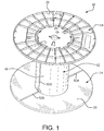
- the spool 10 is comprised of a barrel 12 and one or more flanges 14. Two flanges 14 are shown in the figures, although a functional winding spool may include only a single flange if desired.
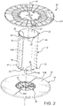
- the barrel 12 as shown is preferably defined by an annular winding surface 16, which is generally formed about a longitudinal axis 18 (see Fig. 2 ). As shown, the barrel has a singular form, with all portions integrally formed as a single piece. The barrel may be assembled from multiple pieces.
- Each flange 14 includes a support surface 20 directed inwardly towards the winding surface 16 of the barrel 12 in the assembled spool.
- the winding surface 16 and the support surface(s) 20 engage the elongate material (not shown) to be wound on the spool 10.
- the barrel 12 includes an insertion section 22 on each longitudinal end 24.
- a central recess 26 is provided within the support surface 20 of the flange 14 and has a generally circular form. The dimensions of the flange recess 26 are defined to receive and engage the insertion section 22 of the barrel 12.
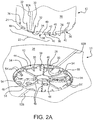
- An enlarged view of the insertion section 22 and recess 26 is shown in Fig. 2A .
- the connection of one of the flanges 14 to one end 24 of the barrel is described below. It should be understood that in the preferred two-flange construction, each flange will be formed in a similar fashion, as will each end of the barrel.
- the barrel structure is contemplated to be integrally molded from a thermoplastic material.
- the flanges preferably include an integrally molded construction.
- the insertion section 22 of the end 24 of the barrel 12 includes two separate engagement elements that combined to axially and rotationally fix the barrel 12 within the central recess 26 of each flange 14.
- a first engagement element is formed in part by the locking tab 30 that is formed within the winding surface 16 of the barrel 12.
- the locking tab 30 is defined between two slots 32 in the wall of the barrel 12. As shown, the slots extend axially from edge of the longitudinal end 22 of the barrel 12. The slots 32 diverge as they extend along the wall of the barrel 12, with the slots being closer to one another at the barrel end 22. In its normal position, the tab 30 is aligned with barrel wall.
- a projecting cleat or abutment 34 is formed on the end of the tab 30 and projects radially outward from the winding surface 16 of the barrel 12.
- the base of the tab 30 is integrally formed with the wall 16 of barrel 12.
- the form of the tab 30 and the material of the barrel 12 provide flexibility to the tab 30, permitting it to resiliently move inwardly (and outwardly) relative to the remainder of the barrel 12.
- a second tab 30' of similar form is provided diametrically opposite of the first tab 30 on the end 24 of the barrel 12.
- the two tabs 30, 30' on one end 24 of the barrel 12 are shown in the exploded view of Fig 2 .
- a similar arrangement is provided on the opposite end, which is also shown in Fig. 2A .
- a second engagement element is formed in part on the barrel 12 by a series of locking clips 36 provided around the periphery of the two ends 24 of the barrel 12.
- Fig. 2A shows the clips 36 spaced from one another around the insertion section 22 of the barrel 12 on both sides of the locking tab 30.
- Each clip 36 includes a base hook portion 41 that is surrounded by a channel 38 formed within the wall of the barrel 12.
- Each channel 38 includes an outer release portion 40 and inner retention portion 42.
- the hook portion 41 is axially aligned with the retention portion 42 of the channel 38.
- the channels 38 and hooks 41 of the multiple clips 36 are formed in the same direction around the periphery of the barrel end 24.
- the portion of the flange 14 shown in Fig. 2A includes the central recess 26.
- the recess 26 is formed in the support surface 20.
- An outer wall 44 defines the perimeter of the recess 26 and creates a shoulder with the adjacent support surface 20.
- a series of support ribs 46 extend radially outward from an arbor opening 48 in the center of the recess 26. The support ribs 46 serve at least in part to strengthen the flange 14.
- Other support structures, such as corrugations, may be provided in the central recess 26.
- a support ring 50 is provided inward of the outer wall 44. The spacing between the wall 44 and the ring 50 creates a receiving channel 52 for receipt of the insertion section 22 of the barrel 12, which is preferably hollow.
- Angled projections 54 are provided on the ends of the support ribs 46, adjacent to or overlapping with the ring 50.
- An additional set of angled projections 54' are provided at various positions between the radial ribs 46.
- the angled projections 54, 54' serve to guide the insertion section 22 of the barrel 12 into the receiving channel 52.
- the ring 50 and projections 54. 54' support the engagement of the insertion section 22 in the channel 52.
- openings 56, 56' positioned diametrically opposite one another.
- the wall openings 56, 56' form a part of the first engagement elements and are aligned with the locking tabs 30, 30' within the insertion section 22 of the barrel 12.
- receiving channels 58 are provided on the outer wall 44 in alignment with the clips 36 on the insertion section 22 of the barrel 12.
- Other openings, structures and marking indicia may be provided within the central recess 26 or associated with the flange or barrel.
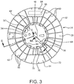
- Fig. 3 there is shown the outside or top surface 28 of a flange 14, with the barrel 12 engaged within the receiving channel 52 on the opposite side of the flange 14.
- the top surface 28 of the flange 14 includes a plurality of raised ribs 60 generally projecting radially. As shown, the raised ribs 60 are joined with the outside of wall 44 and extend to an outer rim 62. Substantially circular ribs 70, 72 intersect with the radial top ribs 60. The circular ribs 70, 72 are concentric with the outer rim 62 of the flange 14 and the radially inward positioned outside wall 44. Open areas 64 are provided in the top surface 28 for identification labels 66 and the like.
- Access openings 68, 68' are provided adjacent the wall openings 56, 56'.
- the projecting cleats 34 on the tabs 30, 30' engage within the wall openings 56, 56' and are viewed through the access openings 68, 68'.
- the engagement of the cleat 34 with a lip 74 formed by the wall opening 56 is shown in the cross section of Fig. 4A .
- the flexible tab 30 formed within the wall 16 of the barrel 12 is flexed inwardly (see arrows 76 in Fig. 5 ) to permit the cleat 34 to move around the lip 74 and into the opening 56.
- the tab 30 flexes back to its normal position and the cleat 34 axially overlaps with the lip 74.
- the support ring 50 and ribs 46 are spaced from the wall openings 56, providing clearance for the tabs 30.
- the cleat 34 on the end of the tab 30 includes an angled engagement edge 86 to assist in guiding the cleat 34 past the lip 74 of the opening 56 (and 56').
- Fig. 5 there is shown a partial perspective view of the flange 14 with the barrel (12) engaged.
- Arrows 76 represent a release force being applied to the ends of the tabs 30, 30'.
- the release force 76 moves the cleats 34, 34' radially inward and out of engagement with the lip 74 formed at the openings 56, 56'.
- a separate rotational force is illustrated by arrow 78 and is discussed in further detail below.
- Fig. 4A shows the engagement of the cleat portion 34 of the flexible tab 30 of the barrel 12 with the lip 74 of the wall opening 56 in the outer wall 44 of the recess 26 in the flange 14. Also included in this figure is an alignment nub or tab 88 shown as part of the flexible tab 30 portion of the barrel 12.
- the tab 88 is shown in alignment with an added alignment slot 90 formed in the support surface 20 of the flange 14, adjacent to the outer wall 44.
- Positional indicia shown as lines 92A and 92B, is provided on the surfaces of the barrel 12 and flange 14.
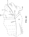
- the positional indicia 92A, 92B respectively identify the position for the tabs 30, 30' on the barrel end 22 and the wall openings 56, 56' as shown in, for example, Fig. 4D .
- the alignment tab 88 moves into the alignment slot 90.
- the alignment tab 88 slides into the channel 90 as the flexible tab 30 flexes and the cleat 34 moves around the lip 74 adjacent the opening in the wall of the central recess.
- the alignment tab 88 and slot 90 may be replaced by other structures that force an alignment of the barrel 12 with the flanges 14 during introduction of the insertion section 22 into the central recess 26.
- the alignment structures may be omitted with the alignment relying on, for example, the positioning of the tabs 30, 30' with the wall openings 56, 56'.
- Fig. 6A there is shown in partial cross section the engagement between the clips 36 on the insertion section 22 of the barrel 12 and the receiving clips 58 formed on the outside wall 44 of the flange 14.
- the secondary engagement structure is formed by the engagement of the separate clip structures 36, 58, as is also shown in cross section of Fig 6B .
- the insertion clips 36 formed on the end 22 of the barrel 12 have a shape corresponding to the receiving clips 58.
- the base hook 80 of the flange clip 58 is positioned within the retention portion 42 of the release channel 40 of the barrel clip 36.
- the base hook 41 of the barrel clip 36 overlaps with the corresponding base portion 80 of the flange clip 58 to axially fix the flange and barrel 12.
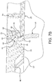
- Figs. 7A , 7B and 7C Creation of the overlapping relationship of the barrel clip 36 and the flange clip 58, as shown in Figs 6A and 6B , is illustrated in the sequence of Figs. 7A , 7B and 7C .
- the barrel clips 36 and flange clips 58 are aligned. This alignment is created by their positional relationship with respect to the tabs 30, 30' and the openings 56, 56' and the provided alignment structures including alignment tab 88, alignment slot 90, and indicia 92A, 92B.
- the barrel 12 is inserted axially into the flange recess 26 in the direction shown by arrow 94.
- the base hook portion 41 of the insertion clip 36 on the end 22 of the barrel 12 is positioned radially outward on the barrel wall 16 and at the edge of the barrel end 22.
- the hook 80 for the flange clip 58 is positioned on the outer wall 44, adjacent the support surface 20.
- An angled surface 84 is provided on the flange hook 80 and a corresponding angled surface 82 is formed on the base hook 41 of the barrel clip 36.
- the angled surfaces 82, 84 are provided to assist in the continued insertion of the interfering clips 36, 58.
- the initial contact between the two base hook portions 41, 80 causes the barrel end 22 to flex radially inward.
- the hook 41 of the clip 36 moves around the base hook 80 of the flange clip 58.
- the deformation of the end 22 of the barrel 12 is contemplated to be a function of the material properties of the barrel end.
- the inner edge of the barrel, opposite the hook 41 engages the angled projections 54, 54' and is also supported by the ring 50 which forms a base support for the inside end of the barrel.
- the clip portions 36, 58 align and engage, as shown in Fig. 7C .
- the base portion 80 of the flange clip 58 engages within the retention portion 42 of the barrel clip 36.
- the tabs 30, 30' engage within the wall openings 56. 56' to axially lock the barrel 12 with respect to flange, as shown in cross section in Fig. 6B .
- the overlap of the clips 36, 58 and the engagement of the cleat 34 with the lip portion 74 of the opening serve to lock the barrel 12.
- the support ring 50 and related projections 54, 54' stiffen the wall of the insertion section 22 of the barrel 12, once the engagement occurs inside the receiving channel 52.
- the positioning of the alignment tab 88 within slot 90 and the engagement of the cleat 34 with the opening in the outer peripheral wall 44 of the receiving channel 52 fixes the rotative position of the barrel 12 within the central opening 26 of the flange 14. Only upon the inward flexing of the tabs 30, 30' (see arrows 76 in Fig.
- the insertion section 22 of the barrel 12 be able to rotate within the central recess 26 of the flange 14.
- the overlap of the clips 36, 58 is removed.
- the base hook portion 41 of each insertion clip 36 is moved into the release portion of the respective flange clip 58.
- the base portion 80 of the receiving clip 58 on the flange 14 moves into the release portion 40 of the insertion clip 36 on the barrel 12.
- the insertion section 22 of the barrel 12 and the central recess 26 of each flange 14 includes first and second engagement elements for releasably securing the flanges to the axial ends of the barrel.
- These engagement elements have different structural forms and provide different forms of engagement, resulting in a locking of the flange to the end of the barrel, until a desired manual release. Further, the first engagement elements and the second engagement elements are separately released.
- the insertion sections 22 of the barrel 12 and the central recess within the flanges also include alignment elements to locate the engagement elements for a proper fixing of the barrel and flange. These alignment elements may also serve to fix the relative rotative position of the barrel and the flange. Release of the alignment elements is also required to release the barrel from the flange.
- the first engagement elements of the embodiment shown include two diametrically opposed flexible tabs 30, 30' formed within the barrel wall 16. It is noted that only one tab is required. In the alternative, additional tabs may be included. However, the inclusion of more than two tabs is not preferred, since it would serve to complicate release of the flange from the barrel.
- the flexible tabs 30, 30' include a base portion and a free end portion. The base portion of the tabs is connected to the barrel wall and the end portions of the tab include a radially outward projecting cleat 34.
- the tabs 30, 30' are capable of flexing radially about the base portion, with the normal (non-flexed) position of the tab being in-line with the winding surface 16 of the barrel 12.
- a pair of receiving openings 56, 56' that are formed within an outer peripheral wall of the central recess 26.
- the openings each define an engagement lip 74, adjacent to the support surface 20 of the flange 14.
- the openings 56, 56' are formed for receiving a projecting cleat 34 on a corresponding tab 30, 30' upon introduction of the insertion section 22 of the barrel 12 into the central recess 26 of the flange 14.
- the tabs are flexed radially inward so that the cleat 34 moves over or around the lip 74.
- the cleat 34 moves into and engages within the opening 56, 56' upon return of the tabs 30, 30' to the non-flexed position.
- the second engagement elements are provided in the form of a plurality of spaced insertion clips 36 on the insertion section 22 of the barrel 12.
- a corresponding plurality of receiving clips 58 is provided on the peripheral wall 44 of the central recess 26.
- the receiving clips 58 are spaced relative to the pair of openings 56, 56' to match up with the insertion clips 36 on the end of the barrel 12.
- the receiving clips 58 are each formed to axially overlap and engage with a corresponding insertion clip 36 upon alignment of the flexible tabs 30, 30' with the openings 56, 56' during introduction of the insertion section 22 of the barrel 14 into the central recess 26 of the flange 14.
- the barrel wall adjacent the insertion clips 36 flexes movement of the insertion clips 36 around the receiving clips 56 to form the overlap and axial engagement.
- ring 50 preferably engages the inside surface of the barrel, adjacent the overlap of the clips to deter or prevent axial separation.
- the engagement of the clips 36, 56 may be release based in a rotation of the flange with respect to the barrel. This rotation is possible only after release of the engagement of the cleats 34 from the lip 74 and opening 56, 56', and other alignment structures, such as the alignment tabs 88 and slots 90. After radially inward flexing of the tabs and axial release of the cleat from the lip and the opening, the relative rotational movement releases the axial overlap and engagement of the respective clips for axial withdrawal of the barrel from the flange.
Landscapes
- Storage Of Web-Like Or Filamentary Materials (AREA)
- Snaps, Bayonet Connections, Set Pins, And Snap Rings (AREA)
- Sliding Valves (AREA)
- Quick-Acting Or Multi-Walled Pipe Joints (AREA)
- Multiple-Way Valves (AREA)
Claims (18)
- Eine zerlegbare Spule (10), beinhaltend:eine Trommel (12), die Folgendes aufweist:eine Längsachse (18),eine Trommelwand, die die Längsachse im Wesentlichen umgibt und eine ringförmige Wickelfläche (16) bildet, undeinen Einsteckabschnitt (22), der an mindestens einem axialen Ende (24) der Trommelwand gebildet ist, wobei der Einsteckabschnitt Folgendes beinhaltet:mindestens eine biegsame Zunge (30), die innerhalb der Trommelwand gebildet ist und eine radial auswärts vorstehende Leiste (34) an einem Ende der Zunge aufweist, undeine Vielzahl von Einstecklaschen (36), die voneinander und von der mindestens einen Zunge beabstandet sind; undmindestens einen Flansch (14), der Folgendes aufweist:eine Stützfläche (20),eine zentrale Aussparung (26), die innerhalb der Stützfläche positioniert ist,wobei die zentrale Aussparung zum Aufnehmen des Einsteckabschnitts der Trommel (12) gebildet ist, wobei die zentrale Aussparung Folgendes beinhaltet:eine erste Öffnung (56) zum Aufnehmen der vorstehenden Leiste auf der mindestens einen Zunge (30) bei ausgerichteter Einführung des Einsteckabschnitts (22) in eine aufnehmende Nut (52), undeine Vielzahl von aufnehmenden Laschen (58), die relativ zu der ersten Öffnung (56) entsprechend dem Abstand der Vielzahl von Einstecklaschen (36) relativ zu der mindestens einen Zunge (30) auf dem Einsteckabschnitt der Trommelwand beabstandet sind, wobei die aufnehmenden Laschen jeweils gebildet sind, um eine entsprechende Einstecklasche axial zu überlappen und damit in Eingriff zu gelangen, wenn die mindestens eine Zunge während der Einführung des Einsteckabschnitts (22) innerhalb der zentralen Aussparung (26) auf die erste Öffnung ausgerichtet ist,wobei sich die mindestens eine Zunge (30) bei Einführung des Einsteckabschnitts in die aufnehmende Nut (52) radial einwärts biegt, wobei die Einwärtsbiegung der mindestens einen Zunge die Leiste (34) zur Bewegung des Einsteckabschnitts (22) in die zentrale Aussparung freigibt und die Rückkehr der mindestens einen Zunge in eine normale Position innerhalb der Trommelwand die Leiste in den Eingriff mit der mindestens einen Öffnung (56) innerhalb der aufnehmenden Nut bewegt,wobei sich die Trommelwand neben den Einstecklaschen (36) zur Bewegung der Einstecklaschen in den Eingriff mit den entsprechenden aufnehmenden Laschen (58) biegt, undwobei die Einstecklaschen und die aufnehmenden Laschen jeweils einen Eingriffsnutteil (38) beinhalten, der daneben gebildet ist, wobei die Eingriffsnut nach dem radialen Einwärtsbiegen der mindestens einen Zunge (30) und der Freigabe der Leiste (34) aus dem Eingriff mit der ersten Öffnung eine Drehbewegung des Flansches (14) relativ zu dem Einsteckabschnitt (22) der Trommel (12) ermöglicht, wobei die Drehbewegung des Flansches und der Trommel die axiale Überlappung und den Eingriff der Laschen zur Wegnahme des Eingriffs der Trommel aus dem Flansch löst.
- Zerlegbare Spule (10) gemäß Anspruch 1, wobei die Trommel (12) mindestens zwei biegsame Zungen (30, 30') beinhaltet, die auf dem Einsteckabschnitt (22) des axialen Endes (24) der Trommel gebildet sind, wobei die mindestens zwei Zungen jeweils eine vorstehende Leiste (34) darauf aufweisen.
- Zerlegbare Spule (10) gemäß Anspruch 2, wobei die mindestens zwei biegsamen Zungen (30, 30') voneinander beabstandet und an dem axialen Ende (24) der Trommel (12) diametral entgegengesetzt positioniert sind.
- Zerlegbare Spule (10) gemäß Anspruch 2, wobei der mindestens eine Flansch (14) ferner eine zweite Öffnung (56') beinhaltet, wobei die erste und die zweite Öffnung (56, 56') jeweils auf die mindestens zwei Zungen (30, 30') an dem axialen Ende der Trommel zur Aufnahme der entsprechenden vorstehenden Leisten (34) ausgerichtet sind.
- Zerlegbare Spule (10) gemäß Anspruch 1, ferner beinhaltend eine Ausrichtungszunge (88), die auf der mindestens einen Zunge (30) gebildet ist, und einen Ausrichtungsschlitz (90), der auf dem Flansch (14) neben der ersten Öffnung (56) gebildet ist, wobei der Ausrichtungsschlitz gebildet ist, um bei Ausrichtung der mindestens einen Zunge und der ersten Öffnung während der Einführung des Einsteckabschnitts (22) in die zentrale Aussparung (26) die Ausrichtungszunge aufzunehmen.
- Zerlegbare Spule (10) gemäß Anspruch 1, wobei die Trommel (12) aus einem thermoplastischen Material integral geformt ist.
- Zerlegbare Spule (10) gemäß Anspruch 1, wobei die Trommel (12) einen im Wesentlichen zentralen Hohlraum beinhaltet, der von einer Innenwand der Wickelfläche (16) definiert wird.
- Zerlegbare Spule (10) gemäß Anspruch 1, wobei die zentrale Aussparung (26) eine äußere Umfangsseitenwand (44) beinhaltet, wobei die erste Öffnung (56) innerhalb der Umfangsseitenwand gebildet ist und die Vielzahl von aufnehmenden Laschen (58) auf der Umfangsseitenwand gebildet ist.
- Zerlegbare Spule (10) gemäß Anspruch 8, wobei die zentrale Aussparung (26) ferner eine innere Stütze beinhaltet, die radial einwärts der Umfangsseitenwand (44) positioniert ist, wobei der Abstand zwischen der inneren Stütze und der Umfangsseitenwand eine Nut definiert, die zum Aufnehmen des Einsteckabschnitts (22) der Trommel (12) gebildet ist, wobei die innere Stütze mit einer Innenwand der Trommel in Eingriff gelangt.
- Zerlegbare Spule (10) gemäß Anspruch 9, wobei die innere Stütze ein Ringelement (50) beinhaltet, wobei das Ringelement eine vorstehende Höhe innerhalb der zentralen Aussparung (26) aufweist, die geringer als eine Höhe der Umfangsseitenwand (44) ist.
- Zerlegbare Spule (10) gemäß Anspruch 10, die ferner eine Vielzahl von sich radial erstreckenden Stützrippen (46) beinhaltet, die innerhalb der zentralen Aussparung (26) einwärts der Stützwand (44) gebildet sind.
- Zerlegbare Spule (10) gemäß Anspruch 11, wobei die innere Stütze ferner eine Vielzahl von abgewinkelten Vorsprüngen (54) beinhaltet, die mit dem Ringelement (50) integral gebildet sind und eine Höhe aufweisen, die größer als die Höhe des Rings ist.
- Zerlegbare Spule (10) gemäß Anspruch 12, wobei die abgewinkelten Vorsprünge (54) eine Lenkfläche beinhalten, die radial einwärts von dem Ringelement (50) abgewinkelt ist.
- Zerlegbare Spule (10) gemäß Anspruch 13, wobei die abgewinkelten Vorsprünge (54) mit den Stützrippen (46) integral gebildet sind.
- Zerlegbare Spule (10) gemäß Anspruch 14, ferner beinhaltend eine zweite Vielzahl von abgewinkelten Vorsprüngen (54'), die von den mit den Stützrippen (46) gebildeten abgewinkelten Vorsprüngen (54) beabstandet sind.
- Zerlegbare Spule (10) gemäß Anspruch 8, wobei die vorstehende Leiste (34) eine abgewinkelte Eingriffsfläche (86) zum Eingreifen in die äußere Umfangsseitenwand (44) neben der ersten Öffnung (56) bei anfänglicher Einführung des Einsteckabschnitts (22) in die zentrale Aussparung (26) beinhaltet.
- Zerlegbare Spule (10) gemäß Anspruch 1, ferner beinhaltend Ausrichtungszeichen auf der Trommelwand und auf der Flanschstützfläche, wobei die Ausrichtungszeichen (92A, 92B) die positionelle Lage der mindestens einen Zunge (30) auf dem Einsteckabschnitt (22) und der ersten Öffnung (56) innerhalb der zentralen Aussparung (26) anzeigen.
- Zerlegbare Spule (10) gemäß Anspruch 1, beinhaltend:jeweils einen Einsteckabschnitt (22), der an jedem axialen Ende (24) der Trommelwand gebildet ist, wobei die Einsteckabschnitte jeweils Folgendes beinhalten:zwei diametral entgegengesetzte biegsame Zungen (30), die innerhalb der Trommelwand gebildet sind, wobei jede Zunge einen Basisteil und einen freistehenden Endteil aufweist, wobei die Zungen an dem Basisteil mit der Trommelwand verbunden sind und die Endteile eine radial auswärts vorstehende Leiste (34) darauf aufweisen, wobei die Zungen in der Lage sind, sich radial um den Basisteil zu biegen, undeine Vielzahl von Einstecklaschen (36), die voneinander und von den zwei Zungen beabstandet sind; undein Paar ähnlich gebildete Flanschelemente (14), wobei jedes Flanschelement Folgendes aufweist:eine Stützfläche (20),eine zentrale Aussparung (26), die innerhalb der Stützfläche positioniert ist,wobei die zentrale Aussparung zum Aufnehmen des Einsteckabschnitts der Trommel gebildet ist, wobei die zentrale Aussparung Folgendes beinhaltet:eine äußere Umfangswand (44), wobei die Umfangswand einen Innendurchmesser aufweist, der eng an einem Außendurchmesser der ringförmigen Wickelfläche der Trommelwand bemessen ist,ein Paar aufnehmende Öffnungen (56), die innerhalb der äußeren Umfangswand gebildet sind, wobei die Öffnungen jeweils eine Eingriffslippe (74) neben der Stützfläche definieren, wobei die Öffnungen zum Aufnehmen der vorstehenden Leisten auf den Zungen bei Einführung der Einsteckabschnitte der Trommel in die zentralen Aussparungen eines jeweiligen Flansches gebildet sind, undeine Vielzahl von aufnehmenden Laschen (58), die relativ zu dem Paar Öffnungen beabstandet sind, wobei der Abstand der aufnehmenden Laschen dem Abstand der Vielzahl von Einstecklaschen relativ zu der biegsamen Zunge auf den Einsteckabschnitten der Trommelwand entspricht, wobei die aufnehmenden Laschen jeweils gebildet sind, um eine entsprechende Einstecklasche bei Ausrichtung der biegsamen Zunge auf die erste Öffnung und Einführung des Einsteckabschnitts innerhalb der aufnehmenden Nut axial zu überlappen und damit in Eingriff zu gelangen,wobei sich jede der Zungen bei Einführung des Einsteckabschnitts eines Endes der Trommel in die aufnehmende Nut eines der Flansche radial einwärts biegt, wobei die Einwärtsbiegung der Zungen die Leiste über der Lippe zur Bewegung der Leiste in die ausgerichtete Öffnung in der Umfangswand der zentralen Aussparung freigibt und die Rückkehr der Zungen in eine normale Position, die auf die Trommelwand ausgerichtet ist, die Leiste in den Eingriff mit der Lippe und der Öffnung in der Umfangswand bewegt, wobei sich die Trommelwand neben den Einstecklaschen zur Bewegung der Einstecklaschen in den Eingriff mit den entsprechenden aufnehmenden Laschen biegt, undwobei jede der Einstecklaschen und der aufnehmenden Laschen jeweils einen Eingriffsnutteil (52) beinhaltet, der daneben gebildet ist, wobei die Eingriffsnut nach dem radialen Einwärtsbiegen der Zungen und der axialen Freigabe der Leiste von der Lippe und der Öffnung eine relative Drehbewegung des Flansches um die Achse der Trommel ermöglicht, wobei die relative Drehbewegung die axiale Überlappung und den Eingriff der jeweiligen Laschen zur axialen Wegnahme der Trommel aus dem Flansch löst.
Priority Applications (3)
| Application Number | Priority Date | Filing Date | Title |
|---|---|---|---|
| PL19179213T PL3564168T3 (pl) | 2015-06-04 | 2016-06-03 | Szpula demontowana z blokadą |
| EP19179213.4A EP3564168B1 (de) | 2015-06-04 | 2016-06-03 | Ausfallspule mit verriegelung |
| PL16730608T PL3303201T3 (pl) | 2015-06-04 | 2016-06-03 | Szpula demontowana z blokadą |
Applications Claiming Priority (2)
| Application Number | Priority Date | Filing Date | Title |
|---|---|---|---|
| US14/730,627 US10155638B2 (en) | 2015-06-04 | 2015-06-04 | Locking breakdown spool |
| PCT/US2016/035612 WO2016196861A1 (en) | 2015-06-04 | 2016-06-03 | Locking breakdown spool |
Related Child Applications (2)
| Application Number | Title | Priority Date | Filing Date |
|---|---|---|---|
| EP19179213.4A Division EP3564168B1 (de) | 2015-06-04 | 2016-06-03 | Ausfallspule mit verriegelung |
| EP19179213.4A Division-Into EP3564168B1 (de) | 2015-06-04 | 2016-06-03 | Ausfallspule mit verriegelung |
Publications (2)
| Publication Number | Publication Date |
|---|---|
| EP3303201A1 EP3303201A1 (de) | 2018-04-11 |
| EP3303201B1 true EP3303201B1 (de) | 2019-10-23 |
Family
ID=56137562
Family Applications (2)
| Application Number | Title | Priority Date | Filing Date |
|---|---|---|---|
| EP16730608.3A Active EP3303201B1 (de) | 2015-06-04 | 2016-06-03 | Ausfallspule mit verriegelung |
| EP19179213.4A Active EP3564168B1 (de) | 2015-06-04 | 2016-06-03 | Ausfallspule mit verriegelung |
Family Applications After (1)
| Application Number | Title | Priority Date | Filing Date |
|---|---|---|---|
| EP19179213.4A Active EP3564168B1 (de) | 2015-06-04 | 2016-06-03 | Ausfallspule mit verriegelung |
Country Status (8)
| Country | Link |
|---|---|
| US (1) | US10155638B2 (de) |
| EP (2) | EP3303201B1 (de) |
| BR (2) | BR122022010120B1 (de) |
| CA (2) | CA2987647C (de) |
| ES (2) | ES2764749T3 (de) |
| MX (1) | MX393785B (de) |
| PL (2) | PL3303201T3 (de) |
| WO (1) | WO2016196861A1 (de) |
Families Citing this family (7)
| Publication number | Priority date | Publication date | Assignee | Title |
|---|---|---|---|---|
| US10183834B2 (en) * | 2015-02-09 | 2019-01-22 | Cisco Technology, Inc. | Tool-less cable retainer |
| JP6750354B2 (ja) * | 2015-07-22 | 2020-09-02 | マックス株式会社 | リール |
| US20220305308A1 (en) * | 2021-03-26 | 2022-09-29 | Msa Technology, Llc | Two-Part Locking Polymer Hub for Cable Self-Retracting Device |
| GB202305336D0 (en) * | 2023-04-12 | 2023-05-24 | Pentre Group Ltd | Reel assembly kit and method of assembly |
| US20240359944A1 (en) * | 2023-04-28 | 2024-10-31 | Vandor Corporation | Media reel with locking arrangement |
| CN121368565A (zh) * | 2023-05-23 | 2026-01-20 | 凡得公司 | 感应粘接卷筒 |
| US20240400344A1 (en) * | 2023-06-05 | 2024-12-05 | Vandor Corporation | Snap-together reel with reinforced tab |
Family Cites Families (18)
| Publication number | Priority date | Publication date | Assignee | Title |
|---|---|---|---|---|
| US3552677A (en) | 1968-12-16 | 1971-01-05 | Plastics Inc | Knockdown spool |
| US3785584A (en) | 1971-11-17 | 1974-01-15 | Albany Int Corp | Snap lock assembly |
| US3822841A (en) | 1972-11-24 | 1974-07-09 | K Campbell | Knockdown reel |
| EP0722419A4 (de) | 1993-10-01 | 1996-12-18 | Creative Plastics & Marketing | Spulenzusammenbau |
| US5575437A (en) | 1995-01-12 | 1996-11-19 | Campbell; Kenneth E. | Knockdown reel |
| US6045087A (en) | 1996-08-26 | 2000-04-04 | Vislocky; Mark | Spool assembly for snap fit of flanges and spindle having guiding members for aligning with the flanges spindle |
| US5868348A (en) | 1998-02-11 | 1999-02-09 | Reel-Core, Inc. | Reel assembly |
| DE29822211U1 (de) | 1998-12-14 | 1999-02-04 | Häfner & Krullmann GmbH, 33818 Leopoldshöhe | Wickelspule |
| AUPQ899800A0 (en) | 2000-07-25 | 2000-08-17 | Viscount Plastics (Nsw) Ltd | Collapsible reel assembly |
| ES2241419B1 (es) | 2003-02-14 | 2007-02-16 | Angel Lorenzo Barroso | Carrete desmontable. |
| ES2264330B1 (es) | 2004-06-18 | 2007-11-16 | Angel Lorenzo Barroso | Carrete desmontable con dispositivo de bloqueo. |
| US20070181739A1 (en) | 2006-02-06 | 2007-08-09 | Derendal Thaddeus J | Flexible material storage device |
| US20070262192A1 (en) | 2006-02-06 | 2007-11-15 | Derendal Thaddeus J | Storage and transport device for flexible material and method of making same |
| US7828242B2 (en) | 2008-07-29 | 2010-11-09 | Reynolds Consumer Products, Inc. | Reusable take-apart spool and methods |
| CA2719908C (en) | 2009-11-06 | 2014-04-01 | Bill Ito | Spool assembly |
| US8424796B2 (en) | 2010-04-15 | 2013-04-23 | Direct Wire & Cable, Inc. | Reel |
| US8272591B2 (en) | 2011-01-24 | 2012-09-25 | Sonoco, Inc. | Breakdown spool |
| JP6093529B2 (ja) | 2012-09-19 | 2017-03-08 | 株式会社昭和丸筒 | フランジ付き巻芯 |
-
2015
- 2015-06-04 US US14/730,627 patent/US10155638B2/en active Active
-
2016
- 2016-06-03 EP EP16730608.3A patent/EP3303201B1/de active Active
- 2016-06-03 MX MX2017015569A patent/MX393785B/es unknown
- 2016-06-03 CA CA2987647A patent/CA2987647C/en active Active
- 2016-06-03 ES ES16730608T patent/ES2764749T3/es active Active
- 2016-06-03 ES ES19179213T patent/ES2877051T3/es active Active
- 2016-06-03 PL PL16730608T patent/PL3303201T3/pl unknown
- 2016-06-03 PL PL19179213T patent/PL3564168T3/pl unknown
- 2016-06-03 BR BR122022010120-8A patent/BR122022010120B1/pt active IP Right Grant
- 2016-06-03 EP EP19179213.4A patent/EP3564168B1/de active Active
- 2016-06-03 CA CA3170966A patent/CA3170966C/en active Active
- 2016-06-03 BR BR112017025987-7A patent/BR112017025987B1/pt active IP Right Grant
- 2016-06-03 WO PCT/US2016/035612 patent/WO2016196861A1/en not_active Ceased
Non-Patent Citations (1)
| Title |
|---|
| None * |
Also Published As
| Publication number | Publication date |
|---|---|
| EP3564168A1 (de) | 2019-11-06 |
| CA2987647C (en) | 2023-06-27 |
| EP3564168B1 (de) | 2021-04-21 |
| CA2987647A1 (en) | 2016-12-08 |
| MX393785B (es) | 2025-03-24 |
| BR112017025987B1 (pt) | 2022-08-30 |
| BR112017025987A2 (pt) | 2018-08-14 |
| WO2016196861A1 (en) | 2016-12-08 |
| MX2017015569A (es) | 2018-08-14 |
| ES2877051T3 (es) | 2021-11-16 |
| PL3564168T3 (pl) | 2021-10-25 |
| US20160355371A1 (en) | 2016-12-08 |
| US10155638B2 (en) | 2018-12-18 |
| EP3303201A1 (de) | 2018-04-11 |
| ES2764749T3 (es) | 2020-06-04 |
| PL3303201T3 (pl) | 2020-04-30 |
| BR122022010120B1 (pt) | 2023-11-28 |
| CA3170966C (en) | 2024-01-02 |
| CA3170966A1 (en) | 2016-12-08 |
Similar Documents
| Publication | Publication Date | Title |
|---|---|---|
| EP3303201B1 (de) | Ausfallspule mit verriegelung | |
| EP2479131B1 (de) | Zerlegbare Spule | |
| CA2796036C (en) | Reel | |
| US6045087A (en) | Spool assembly for snap fit of flanges and spindle having guiding members for aligning with the flanges spindle | |
| US4726534A (en) | Convertible reel assembly | |
| US5810272A (en) | Snap-on tube and locking collar for guiding filamentary material through a wall panel of a container containing wound filamentary material | |
| US5622333A (en) | Adjustable wire reel | |
| EP4259566B1 (de) | Schliesssystem für zerlegbare spule | |
| KR100423584B1 (ko) | 가늘고 긴 물품 운송용 릴 | |
| US20080061187A1 (en) | Reel assembly | |
| US20250171268A1 (en) | Three piece winding reel | |
| US9140280B2 (en) | Latch to the core fastener | |
| GB2493518A (en) | Cable reel which can be dismantled | |
| EP3612987B1 (de) | Gehäuse für identifikationsvorrichtung | |
| JP5567460B2 (ja) | 保護部材 | |
| US3679039A (en) | Ribbon spool | |
| US20190337753A1 (en) | Multi-step lokreel and clip system | |
| WO2007035999A1 (en) | Construction module, eg spool half | |
| EP4446268A1 (de) | Rollenmontagekit und montageverfahren | |
| JP2015167504A (ja) | 釣り糸スプール |
Legal Events
| Date | Code | Title | Description |
|---|---|---|---|
| STAA | Information on the status of an ep patent application or granted ep patent |
Free format text: STATUS: THE INTERNATIONAL PUBLICATION HAS BEEN MADE |
|
| PUAI | Public reference made under article 153(3) epc to a published international application that has entered the european phase |
Free format text: ORIGINAL CODE: 0009012 |
|
| STAA | Information on the status of an ep patent application or granted ep patent |
Free format text: STATUS: REQUEST FOR EXAMINATION WAS MADE |
|
| 17P | Request for examination filed |
Effective date: 20171129 |
|
| AK | Designated contracting states |
Kind code of ref document: A1 Designated state(s): AL AT BE BG CH CY CZ DE DK EE ES FI FR GB GR HR HU IE IS IT LI LT LU LV MC MK MT NL NO PL PT RO RS SE SI SK SM TR |
|
| AX | Request for extension of the european patent |
Extension state: BA ME |
|
| DAV | Request for validation of the european patent (deleted) | ||
| DAX | Request for extension of the european patent (deleted) | ||
| REG | Reference to a national code |
Ref country code: DE Ref legal event code: R079 Ref document number: 602016022923 Country of ref document: DE Free format text: PREVIOUS MAIN CLASS: B65H0075220000 Ipc: B65H0075140000 |
|
| RIC1 | Information provided on ipc code assigned before grant |
Ipc: B65H 75/22 20060101ALI20190122BHEP Ipc: B65H 75/14 20060101AFI20190122BHEP |
|
| GRAP | Despatch of communication of intention to grant a patent |
Free format text: ORIGINAL CODE: EPIDOSNIGR1 |
|
| STAA | Information on the status of an ep patent application or granted ep patent |
Free format text: STATUS: GRANT OF PATENT IS INTENDED |
|
| INTG | Intention to grant announced |
Effective date: 20190329 |
|
| GRAS | Grant fee paid |
Free format text: ORIGINAL CODE: EPIDOSNIGR3 |
|
| GRAJ | Information related to disapproval of communication of intention to grant by the applicant or resumption of examination proceedings by the epo deleted |
Free format text: ORIGINAL CODE: EPIDOSDIGR1 |
|
| GRAL | Information related to payment of fee for publishing/printing deleted |
Free format text: ORIGINAL CODE: EPIDOSDIGR3 |
|
| STAA | Information on the status of an ep patent application or granted ep patent |
Free format text: STATUS: REQUEST FOR EXAMINATION WAS MADE |
|
| GRAR | Information related to intention to grant a patent recorded |
Free format text: ORIGINAL CODE: EPIDOSNIGR71 |
|
| STAA | Information on the status of an ep patent application or granted ep patent |
Free format text: STATUS: GRANT OF PATENT IS INTENDED |
|
| GRAA | (expected) grant |
Free format text: ORIGINAL CODE: 0009210 |
|
| STAA | Information on the status of an ep patent application or granted ep patent |
Free format text: STATUS: THE PATENT HAS BEEN GRANTED |
|
| INTC | Intention to grant announced (deleted) | ||
| AK | Designated contracting states |
Kind code of ref document: B1 Designated state(s): AL AT BE BG CH CY CZ DE DK EE ES FI FR GB GR HR HU IE IS IT LI LT LU LV MC MK MT NL NO PL PT RO RS SE SI SK SM TR |
|
| INTG | Intention to grant announced |
Effective date: 20190917 |
|
| REG | Reference to a national code |
Ref country code: GB Ref legal event code: FG4D |
|
| REG | Reference to a national code |
Ref country code: CH Ref legal event code: EP |
|
| REG | Reference to a national code |
Ref country code: IE Ref legal event code: FG4D |
|
| REG | Reference to a national code |
Ref country code: DE Ref legal event code: R096 Ref document number: 602016022923 Country of ref document: DE |
|
| REG | Reference to a national code |
Ref country code: AT Ref legal event code: REF Ref document number: 1193431 Country of ref document: AT Kind code of ref document: T Effective date: 20191115 |
|
| REG | Reference to a national code |
Ref country code: NL Ref legal event code: MP Effective date: 20191023 |
|
| REG | Reference to a national code |
Ref country code: LT Ref legal event code: MG4D |
|
| PG25 | Lapsed in a contracting state [announced via postgrant information from national office to epo] |
Ref country code: FI Free format text: LAPSE BECAUSE OF FAILURE TO SUBMIT A TRANSLATION OF THE DESCRIPTION OR TO PAY THE FEE WITHIN THE PRESCRIBED TIME-LIMIT Effective date: 20191023 Ref country code: BG Free format text: LAPSE BECAUSE OF FAILURE TO SUBMIT A TRANSLATION OF THE DESCRIPTION OR TO PAY THE FEE WITHIN THE PRESCRIBED TIME-LIMIT Effective date: 20200123 Ref country code: PT Free format text: LAPSE BECAUSE OF FAILURE TO SUBMIT A TRANSLATION OF THE DESCRIPTION OR TO PAY THE FEE WITHIN THE PRESCRIBED TIME-LIMIT Effective date: 20200224 Ref country code: SE Free format text: LAPSE BECAUSE OF FAILURE TO SUBMIT A TRANSLATION OF THE DESCRIPTION OR TO PAY THE FEE WITHIN THE PRESCRIBED TIME-LIMIT Effective date: 20191023 Ref country code: LV Free format text: LAPSE BECAUSE OF FAILURE TO SUBMIT A TRANSLATION OF THE DESCRIPTION OR TO PAY THE FEE WITHIN THE PRESCRIBED TIME-LIMIT Effective date: 20191023 Ref country code: LT Free format text: LAPSE BECAUSE OF FAILURE TO SUBMIT A TRANSLATION OF THE DESCRIPTION OR TO PAY THE FEE WITHIN THE PRESCRIBED TIME-LIMIT Effective date: 20191023 Ref country code: NO Free format text: LAPSE BECAUSE OF FAILURE TO SUBMIT A TRANSLATION OF THE DESCRIPTION OR TO PAY THE FEE WITHIN THE PRESCRIBED TIME-LIMIT Effective date: 20200123 Ref country code: GR Free format text: LAPSE BECAUSE OF FAILURE TO SUBMIT A TRANSLATION OF THE DESCRIPTION OR TO PAY THE FEE WITHIN THE PRESCRIBED TIME-LIMIT Effective date: 20200124 Ref country code: NL Free format text: LAPSE BECAUSE OF FAILURE TO SUBMIT A TRANSLATION OF THE DESCRIPTION OR TO PAY THE FEE WITHIN THE PRESCRIBED TIME-LIMIT Effective date: 20191023 |
|
| PG25 | Lapsed in a contracting state [announced via postgrant information from national office to epo] |
Ref country code: HR Free format text: LAPSE BECAUSE OF FAILURE TO SUBMIT A TRANSLATION OF THE DESCRIPTION OR TO PAY THE FEE WITHIN THE PRESCRIBED TIME-LIMIT Effective date: 20191023 Ref country code: IS Free format text: LAPSE BECAUSE OF FAILURE TO SUBMIT A TRANSLATION OF THE DESCRIPTION OR TO PAY THE FEE WITHIN THE PRESCRIBED TIME-LIMIT Effective date: 20200224 Ref country code: RS Free format text: LAPSE BECAUSE OF FAILURE TO SUBMIT A TRANSLATION OF THE DESCRIPTION OR TO PAY THE FEE WITHIN THE PRESCRIBED TIME-LIMIT Effective date: 20191023 |
|
| REG | Reference to a national code |
Ref country code: ES Ref legal event code: FG2A Ref document number: 2764749 Country of ref document: ES Kind code of ref document: T3 Effective date: 20200604 |
|
| PG25 | Lapsed in a contracting state [announced via postgrant information from national office to epo] |
Ref country code: AL Free format text: LAPSE BECAUSE OF FAILURE TO SUBMIT A TRANSLATION OF THE DESCRIPTION OR TO PAY THE FEE WITHIN THE PRESCRIBED TIME-LIMIT Effective date: 20191023 |
|
| REG | Reference to a national code |
Ref country code: DE Ref legal event code: R097 Ref document number: 602016022923 Country of ref document: DE |
|
| PG2D | Information on lapse in contracting state deleted |
Ref country code: IS |
|
| PG25 | Lapsed in a contracting state [announced via postgrant information from national office to epo] |
Ref country code: EE Free format text: LAPSE BECAUSE OF FAILURE TO SUBMIT A TRANSLATION OF THE DESCRIPTION OR TO PAY THE FEE WITHIN THE PRESCRIBED TIME-LIMIT Effective date: 20191023 Ref country code: DK Free format text: LAPSE BECAUSE OF FAILURE TO SUBMIT A TRANSLATION OF THE DESCRIPTION OR TO PAY THE FEE WITHIN THE PRESCRIBED TIME-LIMIT Effective date: 20191023 Ref country code: RO Free format text: LAPSE BECAUSE OF FAILURE TO SUBMIT A TRANSLATION OF THE DESCRIPTION OR TO PAY THE FEE WITHIN THE PRESCRIBED TIME-LIMIT Effective date: 20191023 Ref country code: CZ Free format text: LAPSE BECAUSE OF FAILURE TO SUBMIT A TRANSLATION OF THE DESCRIPTION OR TO PAY THE FEE WITHIN THE PRESCRIBED TIME-LIMIT Effective date: 20191023 Ref country code: IS Free format text: LAPSE BECAUSE OF FAILURE TO SUBMIT A TRANSLATION OF THE DESCRIPTION OR TO PAY THE FEE WITHIN THE PRESCRIBED TIME-LIMIT Effective date: 20200223 |
|
| REG | Reference to a national code |
Ref country code: AT Ref legal event code: MK05 Ref document number: 1193431 Country of ref document: AT Kind code of ref document: T Effective date: 20191023 |
|
| PLBE | No opposition filed within time limit |
Free format text: ORIGINAL CODE: 0009261 |
|
| STAA | Information on the status of an ep patent application or granted ep patent |
Free format text: STATUS: NO OPPOSITION FILED WITHIN TIME LIMIT |
|
| PG25 | Lapsed in a contracting state [announced via postgrant information from national office to epo] |
Ref country code: SM Free format text: LAPSE BECAUSE OF FAILURE TO SUBMIT A TRANSLATION OF THE DESCRIPTION OR TO PAY THE FEE WITHIN THE PRESCRIBED TIME-LIMIT Effective date: 20191023 Ref country code: SK Free format text: LAPSE BECAUSE OF FAILURE TO SUBMIT A TRANSLATION OF THE DESCRIPTION OR TO PAY THE FEE WITHIN THE PRESCRIBED TIME-LIMIT Effective date: 20191023 |
|
| 26N | No opposition filed |
Effective date: 20200724 |
|
| PG25 | Lapsed in a contracting state [announced via postgrant information from national office to epo] |
Ref country code: AT Free format text: LAPSE BECAUSE OF FAILURE TO SUBMIT A TRANSLATION OF THE DESCRIPTION OR TO PAY THE FEE WITHIN THE PRESCRIBED TIME-LIMIT Effective date: 20191023 Ref country code: SI Free format text: LAPSE BECAUSE OF FAILURE TO SUBMIT A TRANSLATION OF THE DESCRIPTION OR TO PAY THE FEE WITHIN THE PRESCRIBED TIME-LIMIT Effective date: 20191023 |
|
| PG25 | Lapsed in a contracting state [announced via postgrant information from national office to epo] |
Ref country code: MC Free format text: LAPSE BECAUSE OF FAILURE TO SUBMIT A TRANSLATION OF THE DESCRIPTION OR TO PAY THE FEE WITHIN THE PRESCRIBED TIME-LIMIT Effective date: 20191023 |
|
| REG | Reference to a national code |
Ref country code: CH Ref legal event code: PL |
|
| PG25 | Lapsed in a contracting state [announced via postgrant information from national office to epo] |
Ref country code: LU Free format text: LAPSE BECAUSE OF NON-PAYMENT OF DUE FEES Effective date: 20200603 |
|
| REG | Reference to a national code |
Ref country code: BE Ref legal event code: MM Effective date: 20200630 |
|
| PG25 | Lapsed in a contracting state [announced via postgrant information from national office to epo] |
Ref country code: CH Free format text: LAPSE BECAUSE OF NON-PAYMENT OF DUE FEES Effective date: 20200630 Ref country code: LI Free format text: LAPSE BECAUSE OF NON-PAYMENT OF DUE FEES Effective date: 20200630 Ref country code: IE Free format text: LAPSE BECAUSE OF NON-PAYMENT OF DUE FEES Effective date: 20200603 |
|
| PG25 | Lapsed in a contracting state [announced via postgrant information from national office to epo] |
Ref country code: BE Free format text: LAPSE BECAUSE OF NON-PAYMENT OF DUE FEES Effective date: 20200630 |
|
| PG25 | Lapsed in a contracting state [announced via postgrant information from national office to epo] |
Ref country code: TR Free format text: LAPSE BECAUSE OF FAILURE TO SUBMIT A TRANSLATION OF THE DESCRIPTION OR TO PAY THE FEE WITHIN THE PRESCRIBED TIME-LIMIT Effective date: 20191023 Ref country code: MT Free format text: LAPSE BECAUSE OF FAILURE TO SUBMIT A TRANSLATION OF THE DESCRIPTION OR TO PAY THE FEE WITHIN THE PRESCRIBED TIME-LIMIT Effective date: 20191023 Ref country code: CY Free format text: LAPSE BECAUSE OF FAILURE TO SUBMIT A TRANSLATION OF THE DESCRIPTION OR TO PAY THE FEE WITHIN THE PRESCRIBED TIME-LIMIT Effective date: 20191023 |
|
| PG25 | Lapsed in a contracting state [announced via postgrant information from national office to epo] |
Ref country code: MK Free format text: LAPSE BECAUSE OF FAILURE TO SUBMIT A TRANSLATION OF THE DESCRIPTION OR TO PAY THE FEE WITHIN THE PRESCRIBED TIME-LIMIT Effective date: 20191023 |
|
| PGFP | Annual fee paid to national office [announced via postgrant information from national office to epo] |
Ref country code: PL Payment date: 20250522 Year of fee payment: 10 Ref country code: DE Payment date: 20250627 Year of fee payment: 10 |
|
| PGFP | Annual fee paid to national office [announced via postgrant information from national office to epo] |
Ref country code: GB Payment date: 20250627 Year of fee payment: 10 |
|
| PGFP | Annual fee paid to national office [announced via postgrant information from national office to epo] |
Ref country code: FR Payment date: 20250625 Year of fee payment: 10 |
|
| PGFP | Annual fee paid to national office [announced via postgrant information from national office to epo] |
Ref country code: ES Payment date: 20250701 Year of fee payment: 10 |
|
| PGFP | Annual fee paid to national office [announced via postgrant information from national office to epo] |
Ref country code: IT Payment date: 20250619 Year of fee payment: 10 |