EP3303110B1 - Saddle for a vehicle - Google Patents
Saddle for a vehicle Download PDFInfo
- Publication number
- EP3303110B1 EP3303110B1 EP16730906.1A EP16730906A EP3303110B1 EP 3303110 B1 EP3303110 B1 EP 3303110B1 EP 16730906 A EP16730906 A EP 16730906A EP 3303110 B1 EP3303110 B1 EP 3303110B1
- Authority
- EP
- European Patent Office
- Prior art keywords
- section
- seating structure
- distance
- saddle
- wing
- Prior art date
- Legal status (The legal status is an assumption and is not a legal conclusion. Google has not performed a legal analysis and makes no representation as to the accuracy of the status listed.)
- Active
Links
Images


Classifications
-
- B—PERFORMING OPERATIONS; TRANSPORTING
- B62—LAND VEHICLES FOR TRAVELLING OTHERWISE THAN ON RAILS
- B62J—CYCLE SADDLES OR SEATS; AUXILIARY DEVICES OR ACCESSORIES SPECIALLY ADAPTED TO CYCLES AND NOT OTHERWISE PROVIDED FOR, e.g. ARTICLE CARRIERS OR CYCLE PROTECTORS
- B62J1/00—Saddles or other seats for cycles; Arrangement thereof; Component parts
- B62J1/08—Frames for saddles; Connections between saddle frames and seat pillars; Seat pillars
-
- B—PERFORMING OPERATIONS; TRANSPORTING
- B62—LAND VEHICLES FOR TRAVELLING OTHERWISE THAN ON RAILS
- B62J—CYCLE SADDLES OR SEATS; AUXILIARY DEVICES OR ACCESSORIES SPECIALLY ADAPTED TO CYCLES AND NOT OTHERWISE PROVIDED FOR, e.g. ARTICLE CARRIERS OR CYCLE PROTECTORS
- B62J1/00—Saddles or other seats for cycles; Arrangement thereof; Component parts
- B62J1/007—Saddles with specific anatomical adaptations
-
- B—PERFORMING OPERATIONS; TRANSPORTING
- B62—LAND VEHICLES FOR TRAVELLING OTHERWISE THAN ON RAILS
- B62J—CYCLE SADDLES OR SEATS; AUXILIARY DEVICES OR ACCESSORIES SPECIALLY ADAPTED TO CYCLES AND NOT OTHERWISE PROVIDED FOR, e.g. ARTICLE CARRIERS OR CYCLE PROTECTORS
- B62J1/00—Saddles or other seats for cycles; Arrangement thereof; Component parts
- B62J1/02—Saddles resiliently mounted on the frame; Equipment therefor, e.g. springs
Definitions
- the present invention relates to a novel saddle for a vehicle, such as a bicycle or a motorcycle, in particular an ergonomic saddle.
- the saddles proposed thus far have complex structures, particularly with reference to the means for coupling the fork to the shell.
- EP 2 003 046 A2 discloses a saddle according to the state of the prior art.
- An object of the present invention is to provide a new saddle for vehicles, in particular for bicycles or motorcycles.
- Another object of the present invention is to provide a novel saddle that is comfortable and ergonomic.
- Another object of the present invention is to provide a novel saddle that does not cause strain on the ischial bones of a user in a harmful or annoying manner.
- Another object of the present invention is to provide a novel saddle that ensures a good distribution of the user's weight.
- Another object of the present invention is to provide a novel saddle that is less rigid than traditional saddles.
- a saddle 1 according to the present invention is shown, for a vehicle, a bicycle or a motorcycle, which includes a seating structure 2, 3 and a fork member or rail 4 secured below the seating structure 2, 3 or better to a base component 2 of the same.
- the seating structure may advantageously include a base component or shell 2 as well as a padding component 3 mounted on and partially around the base component or shell 2.
- the padding component 3 may be removably connected to the base component 2, or attached to it, such as glued or molded, possibly by injection, onto it.
- the padding component 3 may be substantially in one piece or have an external cover element wrapping an actual padding element of soft material.
- the saddle 1 preferably has then a longitudinal symmetry axis x-x, in which case such axis is a longitudinal symmetry or front F-rear R axis at least of the base component 2, of the padding component 3 and of the fork member 4.
- the base component 2 comprises an upper, in use, surface 2a as well as a lower, in use, surface 2b while the padding component comprises an upper, in use, face 3a and a lower, in use, face 3b designed to engage, the upper, in use, surface 2a of the base component 2, such as abutting on or facing towards it.
- the upper surface 2a of the base component 2 is substantially configured as the lower face 3b of the padding component 3, so that the same, once saddle 1 has been assembled, can be engaged or abutted against each other by the entire extension thereof.
- the upper surface 3a of the padding component 3 is, in use, substantially free and designed to be the seating surface for a user.
- the padding component 3 is made of a soft material and, in particular, softer than the base component 2.
- the padding may be made of a material such as polyurethane foam, an elastomeric material or the like.
- the padding component 3 can have a first side wall 3g extending, in use, downwards past the lower face 3b and optionally by the entire annular perimeter of the padding component 3, so as to define with the lower face 3b a receiving and partial wrapping area RZ of the base component 2, or better of the upper surface 2a thereof and optionally, of part of the sides of the same.
- the base component 2 may have a second side wall 2g extending, in use, downwards past the lower surface 2b and optionally by the entire annular perimeter of the base component 2, which second side wall 2g is wrapped, at least partially, by the first side wall 3g.
- the fork member 4 has a pair of prongs 4a, each having a rear end 4b, in use, and a front end 4c, in use.
- the front ends 4c of prongs 4a are constrained to the seating structure 2, 3 or better to a base component 2 of the same, such as will be better described hereinafter.
- the front ends 4c of the prongs are joined bridge-like by a U-shaped connecting portion 4g.
- saddle 1 comprises an anchoring or suspension component 5 of each rear end 4b of prongs 4a of the fork member 4 to the seating structure 2, 3.
- the anchoring or suspension component 5 optionally has a substantially C-shaped structure.
- the anchoring component 5 is connected to the seating structure 2, 3 or better to the base component 2 of the same at a zone of constraint 5a and is configured in such a way that the rear ends 4b of the fork member 4 are connected to the anchoring component 5 at a distance D2 one from the other smaller than the width D1 (see for example figure 11 ) of the zone of constraint 5a and optionally at a distance D6 from the rear R greater than the distance of the zone of constraint 5a from the rear R (see for example figure 4 ).
- the anchoring component 5 may be of a plastic material, such as charged or non-charged thermoplastic, or metal or composite material.
- the anchoring component 5 comprises two wing sections 5b, 5c, each wing section 5c having a first end 5b1, 5c1 proximal to and of constraint for the seating structure 2, 3 and a second end 5b2, 5c2 distal from the seating structure.
- the anchoring component 5 comprises an intermediate section 5a, defining the zone of constraint, connected to the seating structure 2, 3 as well as two wing sections 5b, 5c, each wing section 5b, 5c extending starting from the intermediate section 5a and having a first end 5b1, 5c1 proximal or of connection/coupling to the intermediate section 5a as well as a second end 5b2, 5c2 distal from the intermediate section 5a. More in particular, the anchoring component 5 is connected directly to or in contact with the seating structure 2, 3, or rather with the base component 2 of the same, for example with the lower surface 2b of the base component 2.
- the first ends 5b1, 5c1 of the wing sections 5b, 5c are at a first distance D1 one with respect to the other, while the second ends 5b2, 5c2 of the wing sections 5b, 5c are at a second distance D2 one with respect to the other smaller than the first distance D1.
- a fork is created with this expedient having with rear ends 4b of the respective prongs 4a at a smaller distance than the length of the zone of constraint 5a of the anchoring component 5, which also ensures greater flexibility of the sides or side portions of the saddle in use compared to the prior art solutions.
- each second end 5b2, 5c2 of the wing sections 5b, 5c delimits an engagement seat 6, open towards the front F and/or towards the rear R of the saddle and optionally blind and not through, of a respective rear end 4b of a respective prong 4a of the fork member 4.
- the engagement seat 6 has a main axis of insertion horizontal or inclined with rear end or end proximal to the rear R at a level lower than the respective front end or end distal from the rear R, this in particular for the constraint to a fork which will be described hereinafter.
- the first ends 5b1, 5c1 of the wing sections 5b, 5c are at a third distance D3 from the seating structure 2, 3, in particular from the lower surface 2b of the base component 2, equal to or greater than zero, while the second ends 5b2, 5c2 of the wing sections 5b, 5c are at a fourth distance D4 from the seating structure 2, 3, in particular from the lower surface 2b of the base component 2; the fourth distance D4 is greater than the third distance D3.
- the difference between the fourth distance D4 and the third distance D3 corresponds, in essence, to the height of the anchoring component 5.
- each wing section 5b is substantially curved with concave side facing towards the other wing section 5c or towards axis x-x.
- the wing sections 5b, 5c have a first segment 5b3, 5c3 substantially aligned or with a first inclination or curvature with respect to the intermediate section 5a and then a second segment 5b4, 5c4 with a second inclination or curvature with respect to the intermediate section 5a greater than the first inclination or curvature, so that each wing section 5b, 5c extends laterally from the intermediate section 5a in substantial alignment or with a first inclination or curvature with respect to the intermediate section 5a until reaching a maximum width and then each wing section 5b, 5c develops in the direction of its middle or of axis x-x with a second inclination or curvature greater than the first inclination or curvature.
- the first ends 5b1, 5c1 of the wing sections 5b, 5c are at the rear R of the seating structure 2, 3 or at a fifth distance D5 from it, while the second ends 5b2, 5c2 of the wing sections 5b, 5c are at a sixth distance D6 from the rear R of the seating structure 2, 3 greater than the fifth distance D5 of the first ends 5b1, 5c1 from the rear R, that is to say that the wing sections 5b, 5c move away from the rear R when passing from the respective first 5b1, 5c1 to the respective second 5b2, 5c2 ends.
- prongs 4a of fork 4 are constrained to the anchoring component 5 away or at a distance D6 from the rear R of the structure and/or away or at a distance D4 from the seating structure 2, 3 or better from the lower surface 2b of the base component 2 thereof, resulting in greater comfort of the saddle, since the fork member 4 or better the rear ends 4b of the same do not bump or engage the seating structure while cycling or using the saddle or in any case, are not immediately below the ischial bones of a user during use, which also allows greater comfort and greater flexibility or elasticity of the base component 2 while cycling, because the same is not inferiorly hampered by prongs 4a of fork 4.
- the anchoring component 5 may be structured differently, such as having wing sections with concavity facing outwards or away from the other wing section but optionally always such as to have distance D1 greater than D2 and/or distance D4 greater than D3 and/or distance D6 from the rear R greater than distance D5 between the first ends 5b1, 5c1 and the rear R.
- the wing sections 5b, 5c comprise a substantially curved plate with substantially constant thickness and diameter and having at the second end 5b2, 5c2 a bulge 5b5, 5c5 delimiting a respective engagement seat 6.
- the whole anchoring or suspension component 5 comprises a plate with substantially constant thickness and diameter.
- the intermediate section 5a may have a smaller width than the wing sections 5b, 5c, so as to define a recess portion 5e with the first ends 5b1, 5c1 of the same.
- the intermediate section 5a may be connected for example by means of screws or bolts or similar means to the seating structure, or rather to the base component 2 thereof or, as an alternative, it may be connected by fitting means to the seating structure or to the base component 2 or clamped between the seating structure or the base component 2 and a mask component fixed by means of screws, bolts or fitting means to the seating structure or to the base component 2.
- two or more first through holes 5d may be formed in the intermediate section 5a (two in the exemplary embodiment), while two or more second through holes 2d are formed in the base component 2, in particular at a rear zone of the same, which in use are each aligned with a respective hole 5d and then a respective screw 15 (shown in fig. 10 ) is inserted in the pairs of holes 2d, 5d thus aligned, locking screws 15 into position, for example by means of a respective bushing 16 or nut.
- a raised portion 18 erects, in use, downwards, optionally integral with the base component 2, which raised portion 18 forms a support or abutment section of the intermediate section 5a of the anchoring component 5.
- fencing or delimiting walls 18a, 18b may be provided in the positioning zone of the intermediate section 5a of the anchoring component 5, so that the intermediate section 5a can be inserted or fitted between the fencing walls 18a, 18b.
- the zone of the base component 2 from which the raised portion 18 projects may have a lighter part 2f or a part with reduced thickness (see fig. 9 ).
- the wing sections 5b, 5c of the anchoring component 5 are substantially symmetrical with respect to the symmetry axis x-x or rather with respect to a vertical plane, in use, passing by the same.
- the anchoring component 5 is preferably made in one piece.
- the anchoring component may comprise multiple parts assembled together or to the seating structure, in which case the two wing sections 5b, 5c may not be connected directly to each other, but each separately bound to the seating structure or to the base component 2.
- the distance of the same from the seating structure or rather from the lower surface 2b of the base component 2 may increase in the passage from the front ends 4c to the rear ends 4b of the fork member 4, and thus not have end or rear sections with distance from the seating structure smaller with respect to the front sections of the same.
- the fork member 4 may for example, as shown in fig. 16 , have a first front section 4d constrained to the seating structure 2, 3 and a second rear section 4e terminating in a substantially shank-shaped portion defining a respective rear end 4b.
- the substantially shank-shaped portion 4b is fitted, in use, in a second end 5b2, 5c2 of a respective wing section 5b, 5c or rather in an engagement seat 6 delimited by the same.
- the second rear section 4e of prongs 4a has a distance from the seating structure 2, 3, or rather from the lower surface 2b of the base component 2 of the same, which is growing in the front F-rear R direction, or moving away from the respective first front section 4d.
- each first section 4d and/or each second section 4e of each prong 4a is/are substantially rectilinear or slightly curved.
- the first sections 4d are preferably substantially parallel and the first section 4d of a prong 4a is at a seventh distance D7 from the first section 4d of the other prong 4a.
- the second sections 4e are substantially parallel and the second section 4e of a prong 4a is at an eighth distance D8 from the second section 4e of the other prong 4a, the eighth distance D8 being greater than the seventh distance D7.
- each prong 4a of the fork member 4a has a third connection section 4f of a first front section 4d with a respective second rear section 4e, the third connection section 4f having a distance from the seating structure 2, 3 growing as it moves away from the respective first front section 4d, for example with greater inclination, with respect to the respective first section 4d, than the inclination of the second section 4e with respect to the latter (first section 4d).
- the third connection section 4f, if present, of a prong 4a may be at a distance from the third connection section 4f of the other prong 4a growing as it moves away from the respective first front section 4d and approaching the respective second rear section 4e.
- the fork member 4 is made in a single piece, for example starting from a rod or the like suitably bent or shaped.
- Prongs 4b of the fork member 4 are substantially symmetrical with respect to the symmetry axis x-x or rather with respect to a vertical plane, in use, passing by the same.
- the seating structure 3, 2 or rather the base component 2 of the same may have at the bottom a raised portion 7 which delimits a recess 7a open towards the rear R of the saddle, in which case the front ends 4c of prongs 4a or the U-shaped connecting portion 4g of the same are engaged or fit-inserted into recess 7a.
- the raised portion 7 extends starting from the lower surface 2b of the base component 2 and optionally, is formed in a single piece with it.
- the connecting zone of the front ends 4c of the fork member 4 to the seating structure is substantially aligned with the connecting zone of the anchoring component 5 to the seating structure.
- the raised portion 7 is substantially aligned with the connecting zone of the intermediate section 5a, for example of the free surface of the raised portion 18, if present.
- the saddle may comprise a covering or masking element 19 of the raised portion 7, which masking element 19 is constrainable to the base component 2, for example by the introduction of a pin 19a into a hole 2h delimited by the base component 2 o vice versa.
- the seating structure has a front or tip F substantially tapered, a rear R with width wider than tip P and an intermediate zone IZ of growing width when passing from tip F to the rear R.
- both the base component 2 and the padding component 3 have such a configuration, although the padding component 3 may be slightly larger than the base component 2 so as to delimit the receiving and partial wrapping zone RZ of the same.
- the seating structure may also have a first substantially annular side wall 3g so as to define a substantially continuous flap protruding downwards starting from the lower face 3b.
- the first side wall 3g may have a variable height, i.e. distance from the lower face 3b, and more in particular, maximum height at the sides S1, S2 of the saddle.
- a step or offset 12 is delimited, intended to prevent the slipping towards the rear R of a user sitting on saddle 1.
- the saddle may also comprise a block component 13 fixed to a lower surface 2b of the seating structure and defining therewith a locking or tightening seat of the anchoring component 5.
- the block component 13 advantageously comprises female component of a quick coupling structure or ICS of a fitting or part of a fitting, where fitting means, for example, a bag, a handle, a bottle holder, a light, etcetera.
- the saddle may also include a fitting 14 (a closing component according to the exemplary embodiment shown in the figures) constrained, for example, to said fixing structure 13.
- the block component 13 has a base plate 13a, optionally substantially flat, starting from an outer or lower surface of which, in use, a bridge element 13b projects, delimiting a preferably through opening 16, which may have the function of female part of an ICS in which a fitting 14, or rather a part of the same, may be inserted or fit-inserted.
- One or more through holes 13d may be formed in the base plate 13a (for example shown in figure 10 ) intended, in use, to be aligned with holes 2d, 5d for introducing a screw 15 and a bushing 16 or nut.
- a saddle according to the present invention is therefore more comfortable and ergonomic compared to the prior art solutions, as well as more flexible, particularly at its sides.
- the configuration of the anchoring component allows easy accommodation and engagement of a quick coupling structure.
- a saddle according to the present invention in particular the seating structure thereof, may be made in different sizes and shapes, although all with the structural features described above or at least with the essential features of a saddle according to the present invention, and for example with a slightly narrower seating structure for an "Athletic" saddle, one with an intermediate seating structure to obtain a so-called “Moderate” saddle, and a third one with wider seat for a so-called “Relaxed” saddle.
Description
- The present invention relates to a novel saddle for a vehicle, such as a bicycle or a motorcycle, in particular an ergonomic saddle.
- Many saddles for vehicles have been proposed, which usually comprise a shell and padding connected to each other, as well as a fork constrained inferiorly to the group formed by shell and padding and constrainable to the seat post by means of special clamping jaws.
- These saddles are usually not able to ensure an ergonomic support to a user, in particular taking into account the fact that the fork is anchored to the body at an area, in use, immediately below the ischial bone and therefore causes the application of localized reaction forces on the latter, such as to damage or cause annoyance to the user.
- Moreover, the saddles proposed thus far have complex structures, particularly with reference to the means for coupling the fork to the shell.
-
EP 2 003 046 A2 - An object of the present invention is to provide a new saddle for vehicles, in particular for bicycles or motorcycles.
- Another object of the present invention is to provide a novel saddle that is comfortable and ergonomic.
- Another object of the present invention is to provide a novel saddle that does not cause strain on the ischial bones of a user in a harmful or annoying manner.
- Another object of the present invention is to provide a novel saddle that ensures a good distribution of the user's weight.
- Another object of the present invention is to provide a novel saddle that is less rigid than traditional saddles.
- According to one aspect of the invention, a saddle according to
independent claims - The dependent claims relate to preferred and advantageous exemplary embodiments of the invention.
- Further features and advantages of the invention will become apparent from the description of an exemplary embodiment of a saddle, shown by way of an indication in the accompanying drawings, in which:
-
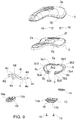
figures 1 and 2 are perspective views, slightly from the top and from the bottom, respectively, of a saddle according to the present invention; -
figures 3 to 8 are front, bottom, top, back view, from one side and from the other side, of the saddle offig. 1 , respectively; -
figures 9 and10 are exploded views from the top and from the bottom, respectively, of the saddle offig. 1 ; -
figures 11 to 14 are front, side, top and back views, respectively, of an anchoring component of the saddle offig. 1 ; and -
figures 15 and 16 are top and side views, respectively, of a fork member of the saddle offig. 1 . - In the accompanying drawings, equal parts or components are designated by the same reference numerals.
- With reference to
Figures 1 to 16 , asaddle 1 according to the present invention is shown, for a vehicle, a bicycle or a motorcycle, which includes aseating structure rail 4 secured below theseating structure base component 2 of the same. - In detail, with regard to the seating structure, it may advantageously include a base component or
shell 2 as well as apadding component 3 mounted on and partially around the base component orshell 2. To this end, thepadding component 3 may be removably connected to thebase component 2, or attached to it, such as glued or molded, possibly by injection, onto it. Moreover, thepadding component 3 may be substantially in one piece or have an external cover element wrapping an actual padding element of soft material. - The
saddle 1 preferably has then a longitudinal symmetry axis x-x, in which case such axis is a longitudinal symmetry or front F-rear R axis at least of thebase component 2, of thepadding component 3 and of thefork member 4. - More in particular, the
base component 2 comprises an upper, in use,surface 2a as well as a lower, in use,surface 2b while the padding component comprises an upper, in use,face 3a and a lower, in use,face 3b designed to engage, the upper, in use,surface 2a of thebase component 2, such as abutting on or facing towards it. Preferably, theupper surface 2a of thebase component 2 is substantially configured as thelower face 3b of thepadding component 3, so that the same, oncesaddle 1 has been assembled, can be engaged or abutted against each other by the entire extension thereof. - Moreover, the
upper surface 3a of thepadding component 3 is, in use, substantially free and designed to be the seating surface for a user. - Preferably, the
padding component 3 is made of a soft material and, in particular, softer than thebase component 2. For example, the padding may be made of a material such as polyurethane foam, an elastomeric material or the like. - Moreover, the
padding component 3 can have afirst side wall 3g extending, in use, downwards past thelower face 3b and optionally by the entire annular perimeter of thepadding component 3, so as to define with thelower face 3b a receiving and partial wrapping area RZ of thebase component 2, or better of theupper surface 2a thereof and optionally, of part of the sides of the same. Moreover, also thebase component 2 may have asecond side wall 2g extending, in use, downwards past thelower surface 2b and optionally by the entire annular perimeter of thebase component 2, whichsecond side wall 2g is wrapped, at least partially, by thefirst side wall 3g. - As regards the
fork member 4, it has a pair ofprongs 4a, each having arear end 4b, in use, and afront end 4c, in use. Thefront ends 4c ofprongs 4a are constrained to theseating structure base component 2 of the same, such as will be better described hereinafter. Moreover, if desired, thefront ends 4c of the prongs are joined bridge-like by aU-shaped connecting portion 4g. - Moreover,
saddle 1 comprises an anchoring orsuspension component 5 of eachrear end 4b ofprongs 4a of thefork member 4 to theseating structure - The anchoring or
suspension component 5 optionally has a substantially C-shaped structure. - The
anchoring component 5 is connected to theseating structure base component 2 of the same at a zone ofconstraint 5a and is configured in such a way that therear ends 4b of thefork member 4 are connected to theanchoring component 5 at a distance D2 one from the other smaller than the width D1 (see for examplefigure 11 ) of the zone ofconstraint 5a and optionally at a distance D6 from the rear R greater than the distance of the zone ofconstraint 5a from the rear R (see for examplefigure 4 ). - The
anchoring component 5 may be of a plastic material, such as charged or non-charged thermoplastic, or metal or composite material. - More in particular, according to the embodiment shown in the figures, the
anchoring component 5 comprises twowing sections wing section 5c having a first end 5b1, 5c1 proximal to and of constraint for theseating structure - The
anchoring component 5 comprises anintermediate section 5a, defining the zone of constraint, connected to theseating structure wing sections wing section intermediate section 5a and having a first end 5b1, 5c1 proximal or of connection/coupling to theintermediate section 5a as well as a second end 5b2, 5c2 distal from theintermediate section 5a. More in particular, theanchoring component 5 is connected directly to or in contact with theseating structure base component 2 of the same, for example with thelower surface 2b of thebase component 2. - The first ends 5b1, 5c1 of the
wing sections wing sections rear ends 4b of therespective prongs 4a at a smaller distance than the length of the zone ofconstraint 5a of theanchoring component 5, which also ensures greater flexibility of the sides or side portions of the saddle in use compared to the prior art solutions. - Moreover, each second end 5b2, 5c2 of the
wing sections engagement seat 6, open towards the front F and/or towards the rear R of the saddle and optionally blind and not through, of a respectiverear end 4b of arespective prong 4a of thefork member 4. Preferably, theengagement seat 6 has a main axis of insertion horizontal or inclined with rear end or end proximal to the rear R at a level lower than the respective front end or end distal from the rear R, this in particular for the constraint to a fork which will be described hereinafter. - Optionally (see
fig. 6 ), the first ends 5b1, 5c1 of thewing sections seating structure lower surface 2b of thebase component 2, equal to or greater than zero, while the second ends 5b2, 5c2 of thewing sections seating structure lower surface 2b of thebase component 2; the fourth distance D4 is greater than the third distance D3. The difference between the fourth distance D4 and the third distance D3 corresponds, in essence, to the height of theanchoring component 5. - Advantageously, each
wing section 5b is substantially curved with concave side facing towards theother wing section 5c or towards axis x-x. - Even more advantageously (see for example
fig. 9 ), thewing sections intermediate section 5a and then a second segment 5b4, 5c4 with a second inclination or curvature with respect to theintermediate section 5a greater than the first inclination or curvature, so that eachwing section intermediate section 5a in substantial alignment or with a first inclination or curvature with respect to theintermediate section 5a until reaching a maximum width and then eachwing section - According to the non-limiting example shown in the figures, the first ends 5b1, 5c1 of the
wing sections seating structure wing sections seating structure wing sections - Due to these measures,
prongs 4a offork 4 are constrained to theanchoring component 5 away or at a distance D6 from the rear R of the structure and/or away or at a distance D4 from theseating structure lower surface 2b of thebase component 2 thereof, resulting in greater comfort of the saddle, since thefork member 4 or better therear ends 4b of the same do not bump or engage the seating structure while cycling or using the saddle or in any case, are not immediately below the ischial bones of a user during use, which also allows greater comfort and greater flexibility or elasticity of thebase component 2 while cycling, because the same is not inferiorly hampered byprongs 4a offork 4. - According to a variant, the
anchoring component 5 may be structured differently, such as having wing sections with concavity facing outwards or away from the other wing section but optionally always such as to have distance D1 greater than D2 and/or distance D4 greater than D3 and/or distance D6 from the rear R greater than distance D5 between the first ends 5b1, 5c1 and the rear R. - Advantageously, the
wing sections respective engagement seat 6. Optionally, the whole anchoring orsuspension component 5 comprises a plate with substantially constant thickness and diameter. - Moreover, the
intermediate section 5a may have a smaller width than thewing sections recess portion 5e with the first ends 5b1, 5c1 of the same. - The
intermediate section 5a may be connected for example by means of screws or bolts or similar means to the seating structure, or rather to thebase component 2 thereof or, as an alternative, it may be connected by fitting means to the seating structure or to thebase component 2 or clamped between the seating structure or thebase component 2 and a mask component fixed by means of screws, bolts or fitting means to the seating structure or to thebase component 2. According to the non-limiting example shown in the figures, two or more first throughholes 5d may be formed in theintermediate section 5a (two in the exemplary embodiment), while two or more second throughholes 2d are formed in thebase component 2, in particular at a rear zone of the same, which in use are each aligned with arespective hole 5d and then a respective screw 15 (shown infig. 10 ) is inserted in the pairs ofholes screws 15 into position, for example by means of a respective bushing 16 or nut. - To this end, according to the non-limiting embodiment example shown in the figures, starting from the
lower surface 2b of thebase component 2, in particular at the rear R, a raisedportion 18 erects, in use, downwards, optionally integral with thebase component 2, which raisedportion 18 forms a support or abutment section of theintermediate section 5a of theanchoring component 5. More in particular, fencing or delimitingwalls intermediate section 5a of theanchoring component 5, so that theintermediate section 5a can be inserted or fitted between thefencing walls - Moreover, the zone of the
base component 2 from which the raisedportion 18 projects may have alighter part 2f or a part with reduced thickness (seefig. 9 ). - The
wing sections anchoring component 5 are substantially symmetrical with respect to the symmetry axis x-x or rather with respect to a vertical plane, in use, passing by the same. - The
anchoring component 5 is preferably made in one piece. According to a variant, the anchoring component may comprise multiple parts assembled together or to the seating structure, in which case the twowing sections base component 2. - As regards the
fork member 4, advantageously, the distance of the same from the seating structure or rather from thelower surface 2b of thebase component 2 may increase in the passage from the front ends 4c to therear ends 4b of thefork member 4, and thus not have end or rear sections with distance from the seating structure smaller with respect to the front sections of the same. - The
fork member 4 may for example, as shown infig. 16 , have afirst front section 4d constrained to theseating structure rear section 4e terminating in a substantially shank-shaped portion defining a respectiverear end 4b. The substantially shank-shapedportion 4b is fitted, in use, in a second end 5b2, 5c2 of arespective wing section engagement seat 6 delimited by the same. In this case, the secondrear section 4e ofprongs 4a has a distance from theseating structure lower surface 2b of thebase component 2 of the same, which is growing in the front F-rear R direction, or moving away from the respective firstfront section 4d. - According to this variant, optionally, each
first section 4d and/or eachsecond section 4e of eachprong 4a is/are substantially rectilinear or slightly curved. Moreover, thefirst sections 4d are preferably substantially parallel and thefirst section 4d of aprong 4a is at a seventh distance D7 from thefirst section 4d of theother prong 4a. Optionally, thesecond sections 4e are substantially parallel and thesecond section 4e of aprong 4a is at an eighth distance D8 from thesecond section 4e of theother prong 4a, the eighth distance D8 being greater than the seventh distance D7. - Optionally, each
prong 4a of thefork member 4a has athird connection section 4f of afirst front section 4d with a respective secondrear section 4e, thethird connection section 4f having a distance from theseating structure front section 4d, for example with greater inclination, with respect to the respectivefirst section 4d, than the inclination of thesecond section 4e with respect to the latter (first section 4d). - The
third connection section 4f, if present, of aprong 4a may be at a distance from thethird connection section 4f of theother prong 4a growing as it moves away from the respective firstfront section 4d and approaching the respective secondrear section 4e. - The
fork member 4 is made in a single piece, for example starting from a rod or the like suitably bent or shaped. -
Prongs 4b of thefork member 4 are substantially symmetrical with respect to the symmetry axis x-x or rather with respect to a vertical plane, in use, passing by the same. - As shown for example in
figure 10 , theseating structure base component 2 of the same may have at the bottom a raisedportion 7 which delimits arecess 7a open towards the rear R of the saddle, in which case the front ends 4c ofprongs 4a or the U-shaped connectingportion 4g of the same are engaged or fit-inserted intorecess 7a. According to the non-limiting embodiment example in the figures, the raisedportion 7 extends starting from thelower surface 2b of thebase component 2 and optionally, is formed in a single piece with it. - Advantageously, the connecting zone of the front ends 4c of the
fork member 4 to the seating structure is substantially aligned with the connecting zone of theanchoring component 5 to the seating structure. Even more advantageously, the raisedportion 7 is substantially aligned with the connecting zone of theintermediate section 5a, for example of the free surface of the raisedportion 18, if present. - Moreover, the saddle may comprise a covering or masking
element 19 of the raisedportion 7, which maskingelement 19 is constrainable to thebase component 2, for example by the introduction of apin 19a into ahole 2h delimited by the base component 2 o vice versa. Moreover, the covering or maskingelement 19, if provided, delimits a pair ofslots 19b for the passage, without engagement or without constraint, of a respective section ofprongs 4a of thefork member 4. - According to the exemplary embodiment shown in the figures, the seating structure has a front or tip F substantially tapered, a rear R with width wider than tip P and an intermediate zone IZ of growing width when passing from tip F to the rear R. Optionally, both the
base component 2 and thepadding component 3 have such a configuration, although thepadding component 3 may be slightly larger than thebase component 2 so as to delimit the receiving and partial wrapping zone RZ of the same. - Moreover, as mentioned, the seating structure may also have a first substantially
annular side wall 3g so as to define a substantially continuous flap protruding downwards starting from thelower face 3b. To this end, thefirst side wall 3g may have a variable height, i.e. distance from thelower face 3b, and more in particular, maximum height at the sides S1, S2 of the saddle. - Advantageously, between tip F and the intermediate zone IZ or at the intermediate zone IZ, a step or offset 12 is delimited, intended to prevent the slipping towards the rear R of a user sitting on
saddle 1. - The saddle may also comprise a
block component 13 fixed to alower surface 2b of the seating structure and defining therewith a locking or tightening seat of theanchoring component 5. Theblock component 13 advantageously comprises female component of a quick coupling structure or ICS of a fitting or part of a fitting, where fitting means, for example, a bag, a handle, a bottle holder, a light, etcetera. In this case, the saddle may also include a fitting 14 (a closing component according to the exemplary embodiment shown in the figures) constrained, for example, to said fixingstructure 13. - According to the non-limiting embodiment example shown in the figures, the
block component 13 has abase plate 13a, optionally substantially flat, starting from an outer or lower surface of which, in use, abridge element 13b projects, delimiting a preferably throughopening 16, which may have the function of female part of an ICS in which a fitting 14, or rather a part of the same, may be inserted or fit-inserted. One or more throughholes 13d may be formed in thebase plate 13a (for example shown infigure 10 ) intended, in use, to be aligned withholes screw 15 and abushing 16 or nut. - A saddle according to the present invention is therefore more comfortable and ergonomic compared to the prior art solutions, as well as more flexible, particularly at its sides.
- Such advantages are obtained due to the configuration of the anchoring component and of the fork member, which components, in fact, cooperate so as to form a substantially annular fork that does not bump into or engages portions of the saddle in turn intended to engage the ischial bones of a user.
- It should also be taken into account that the configuration of the anchoring component allows easy accommodation and engagement of a quick coupling structure.
- Moreover, a saddle according to the present invention, in particular the seating structure thereof, may be made in different sizes and shapes, although all with the structural features described above or at least with the essential features of a saddle according to the present invention, and for example with a slightly narrower seating structure for an "Athletic" saddle, one with an intermediate seating structure to obtain a so-called "Moderate" saddle, and a third one with wider seat for a so-called "Relaxed" saddle.
- Changes and variants of the invention are possible within the scope of protection as defined by the claims.
Claims (20)
- A saddle for a vehicle, a bicycle or a motorcycle comprising:- a seating structure (2, 3),- a fork member (4) secured below said seating structure (2, 3), said fork member (4) having a pair of prongs (4a) each having a rear end (4b) as well as a front end (4c), said front ends (4c) of said prongs (4a) being constrained to said seating structure (2, 3),- at least one anchoring component (5) of each rear end (4b) of said fork member (4) to said seating structure (2, 3),wherein said at least one anchoring component (5) is connected to said seating structure (2, 3) at a zone of constraint (5a) having a width of a first distance (D1) and is configured in such a way that said rear ends (4b) of said fork member (4) are connected to said at least one anchoring component (5)
at a second distance (D2) one from the other smaller than the width (D1) of said zone of constraint (5a) and optionally
at a distance (D6) from the rear (R) of said saddle or of said seating structure (2, 3) greater than the distance (D5) of said zone of constraint (5a) from said rear (R),
wherein said at least one anchoring component (5) comprises two wing sections (5b, 5c), each wing section (5b, 5c) having a first end (5b1, 5c1) proximal to and of constraint to said seating structure (2, 3) and a second end (5b2, 5c2) distal from said seating structure (2, 3), and wherein each second end (5b2, 5c2) of said wing sections (5b, 5c) delimits an engagement seat (6) of a respective rear end (4b) of a respective prong (4a) of said fork member (4),
wherein said first ends (5b1, 5c1) of said wing sections (5b, 5c) are at said first distance (D1) one with respect to the other, while said second ends (5b2, 5c2) of said wing sections (5b, 5c) are at said second distance (D2) one with respect to the other smaller than said first distance (D1),
wherein said at least one anchoring component (5) comprises an intermediate section (5a) connected to said seating structure (2, 3) and defining said zone of constraint and wherein each wing section (5b, 5c) extends starting from said intermediate section (5a) and has the first end (5b1, 5c1) proximal to said intermediate section (5a) and the second end (5b2, 5c2) distal from said intermediate section (5a), and
wherein said intermediate section (5a) is connected by means of screws or bolts or fitting means to said seating structure (2, 3) or said intermediate section (5a) is clamped between said seating structure (2) and a mask component fixed by means of screws, bolts or fitting means to said seating structure (2). - A saddle according to claim 1, wherein said at least one anchoring component (5) is made in one piece.
- A saddle according to any previous claim, wherein said first ends (5b1, 5c1) of said wing sections (5b, 5c) are at a third distance (D3) from said seating structure (2, 3), while said second ends (5b2, 5c2) of said wing sections (5b, 5c) are at a fourth distance (D4) from said seating structure (2, 3) greater than said third distance (D3).
- A saddle according to any previous claim, wherein each wing section (5b, 5c) is substantially curved with concavity facing towards the other wing section (5c, 5b) or facing outwards or away from the other wing section (5c, 5b).
- A saddle for a vehicle, a bicycle or a motorcycle comprising:- a seating structure (2, 3),- a fork member (4) secured below said seating structure (2, 3), said fork member (4) having a pair of prongs (4a) each having a rear end (4b) as well as a front end (4c), said front ends (4c) of said prongs (4a) being constrained to said seating structure (2, 3),- at least one anchoring component (5) of each rear end (4b) of said fork member (4) to said seating structure (2, 3),wherein said at least one anchoring component (5) is connected to said seating structure (2, 3) at a zone of constraint (5a) having a width of a first distance (D1) and is configured in such a way that said rear ends (4b) of said fork member (4) are connected to said at least one anchoring component (5)
at a second distance (D2) one from the other smaller than the width (D1) of said zone of constraint (5a) and optionally
at a distance (D6) from the rear (R) of said saddle or of said seating structure (2, 3) greater than the distance (D5) of said zone of constraint (5a) from said rear (R),
wherein said at least one anchoring component (5) comprises two wing sections (5b, 5c), each wing section (5b, 5c) having a first end (5b1, 5c1) proximal to and of constraint to said seating structure (2, 3) and a second end (5b2, 5c2) distal from said seating structure (2, 3), and wherein each second end (5b2, 5c2) of said wing sections (5b, 5c) delimits an engagement seat (6) of a respective rear end (4b) of a respective prong (4a) of said fork member (4),
wherein said first ends (5b1, 5c1) of said wing sections (5b, 5c) are at said first distance (D1) one with respect to the other, while said second ends (5b2, 5c2) of said wing sections (5b, 5c) are at said second distance (D2) one with respect to the other smaller than said first distance (D1),
wherein said at least one anchoring component (5) comprises an intermediate section (5a) connected to said seating structure (2, 3) and defining said zone of constraint and wherein each wing section (5b, 5c) extends starting from said intermediate section (5a) and has the first end (5b1, 5c1) proximal to said intermediate section (5a) and the second end (5b2, 5c2) distal from said intermediate section (5a),
wherein each wing section (5b, 5c) is substantially curved with concavity facing towards the other wing section (5c, 5b) or facing outwards or away from the other wing section (5c, 5b), and
wherein said wing sections (5b, 5c) have a first segment (5b3, 5c3) with a first inclination or curvature with respect to said intermediate section (5a) and then a second segment (5b4, 5c4) with a second inclination or curvature with respect to said intermediate section (5a) greater than said first inclination or curvature, so that each wing section (5b, 5c) extends laterally from said intermediate section (5a) with a first inclination or curvature with respect to said intermediate section (5a) until reaching a maximum width and then each wing section (5b, 5c) develops in the direction of the middle of the saddle with a second inclination or curvature greater than said first inclination or curvature. - A saddle according to any previous claims, wherein said first ends (5b1, 5c1) of said wing sections (5b, 5c) are at the rear (R) of said saddle or of said seating structure (2, 3) or at a fifth distance (D5) from it, while said second ends (5b2, 5c2) of said wing sections (5b, 5c) are at a sixth distance (D6) from said rear (R) of said seating structure (2, 3) greater than said fifth distance (D5), that is to say that said wing sections (5b, 5c) move away from said rear (R) when passing from the respective first (5b1, 5c1) to the respective second (5b2, 5c2) ends.
- A saddle according to any previous claims, wherein each wing sections (5b, 5c) comprises a substantially curved plate with substantially constant thickness and diameter and having at said second end (5b2, 5c2) a bulge (5b5, 5c5) delimiting the respective engagement seat (6).
- A saddle according to any one of the preceding claims, wherein each prong of said fork member has a first front section (4d) constrained to said seating structure (2, 3) and a second rear section (4e) terminating in a substantially shank-shaped portion defining the respective rear end (4b), said substantially shank-shaped portion (4b) being fitted, in use, in the respective second end (5b2, 5c2) of said at least one anchoring component (5), and wherein said second rear section (4e) has a distance from said seating structure (2, 3) growing as it moves away from the respective first front section (4d).
- A saddle according to claim 8, wherein the first front sections (4d) of said prongs (4a) are substantially parallel, wherein said first front section (4d) of a prong (4a) is at a seventh distance (D7) from said first front section (4d) of the other prong (4a), wherein the second rear sections (4e) of said prongs (4a) are substantially parallel, wherein said second rear section (4e) of a prong (4a) is at an eighth distance (D8) from said second rear section (4e) of the other prong (4a), and wherein said eighth distance (D8) is greater than said seventh distance (D7).
- A saddle according to claim 8 or 9, wherein each prong (4a) of said fork member (4) has a third connection section (4f) for connecting the first front section (4d) with the respective second rear section (4e), said third connection section (4f) having a distance from said seating structure (2, 3) growing as it moves away from the respective first front section (4d).
- A saddle according to claim 10, wherein said third connection section (4f) of a prong (4a) is at a distance from said third connection section (4f) of the other prong (4a) growing as it moves away from the respective first front section (4d) and approaching the respective second rear section (4e).
- A saddle according to any one of the preceding claims, wherein the distance of said fork member (4) from said seating structure (2, 3) increases in passing from said front ends (4c) to said rear ends (4b).
- A saddle according to any one of the preceding claims, wherein said seating structure (2, 3) has at the bottom a raised portion (7) which delimits a recess (7a) open towards the rear (R) of said saddle, said front ends (4c) of said prongs (4a) or a U-shaped connecting portion (4g) of the same being engaged or fitted in said recess (7a).
- A saddle according to any one of the preceding claims, wherein said seating structure comprises a base component or shell (2) as well as a padding component (3) mounted over and partially around said base component or shell (2), said base component (2) comprising an upper, in use, surface (2a), as well as a lower, in use, surface (2b), with said padding component (3) comprising an upper, in use, face (3a) and a lower, in use, face (3b) designed to engage said upper, in use, surface (2a) of said base component (2).
- A saddle according to any one of the preceding claims, wherein said seating structure has a tip (F) substantially tapered, a rear (R) with width wider than said tip (F) and an intermediate zone (IZ) of growing width when passing from said tip (F) to said rear (R) and wherein between said tip (F) and said intermediate zone (IZ) or at said intermediate zone (IZ) a step or offset (12) is delimited intended to prevent the slipping towards the rear (R) of a user.
- A saddle according to any one of the preceding claims, comprising a block component (13) fixed to a lower surface (2b) of said seating structure (2, 3) and defining with said seating structure (2, 3) a locking or tightening space of said at least one anchoring component (5).
- A saddle according to claim 16, wherein said block component (13) comprises a female component of a quick coupling structure of a fitting or part of a fitting (14).
- A saddle according to claim 17, comprising a fitting (14) linked or fixed to said quick coupling structure.
- A saddle according to any one of the preceding claims, wherein each engagement seat (6) is open towards the front (F) and/or towards the rear (R).
- A saddle according to claim 8 and 19, wherein each engagement seat (6) has a main axis of insertion horizontal or inclined with rear end or end proximal to the rear at a level lower than the respective front end or end distal from the rear.
Priority Applications (1)
| Application Number | Priority Date | Filing Date | Title |
|---|---|---|---|
| PL16730906T PL3303110T3 (en) | 2015-05-29 | 2016-05-27 | Saddle for a vehicle |
Applications Claiming Priority (2)
| Application Number | Priority Date | Filing Date | Title |
|---|---|---|---|
| ITUB2015A001030A ITUB20151030A1 (en) | 2015-05-29 | 2015-05-29 | ERGONOMIC SEAT FOR A VEHICLE |
| PCT/IB2016/053116 WO2016193876A1 (en) | 2015-05-29 | 2016-05-27 | Saddle for a vehicle |
Publications (2)
| Publication Number | Publication Date |
|---|---|
| EP3303110A1 EP3303110A1 (en) | 2018-04-11 |
| EP3303110B1 true EP3303110B1 (en) | 2021-04-07 |
Family
ID=53901029
Family Applications (1)
| Application Number | Title | Priority Date | Filing Date |
|---|---|---|---|
| EP16730906.1A Active EP3303110B1 (en) | 2015-05-29 | 2016-05-27 | Saddle for a vehicle |
Country Status (12)
| Country | Link |
|---|---|
| US (1) | US10421513B2 (en) |
| EP (1) | EP3303110B1 (en) |
| JP (1) | JP6843068B2 (en) |
| CN (1) | CN107531299B (en) |
| AU (1) | AU2016272612B2 (en) |
| BR (1) | BR112017022212B1 (en) |
| DK (1) | DK3303110T3 (en) |
| IT (1) | ITUB20151030A1 (en) |
| PL (1) | PL3303110T3 (en) |
| PT (1) | PT3303110T (en) |
| TW (1) | TWI681893B (en) |
| WO (1) | WO2016193876A1 (en) |
Families Citing this family (5)
| Publication number | Priority date | Publication date | Assignee | Title |
|---|---|---|---|---|
| ITUB20160685A1 (en) * | 2016-02-11 | 2017-08-11 | Selle Royal Spa | SADDLE FOR A VEHICLE |
| TWI602730B (en) * | 2016-08-11 | 2017-10-21 | Bicycle seat cushion assembly | |
| DE202017004489U1 (en) * | 2017-08-29 | 2018-12-02 | Ergon International Gmbh | bicycle saddle |
| IT201800005920A1 (en) * | 2018-05-31 | 2019-12-01 | Mold for a support element, for example a vehicle saddle, and a support element obtainable with this mold. | |
| IT202000001699A1 (en) * | 2020-01-29 | 2021-07-29 | Brooks England Ltd | SEAT FOR VEHICLES, SUCH AS BICYCLES |
Citations (1)
| Publication number | Priority date | Publication date | Assignee | Title |
|---|---|---|---|---|
| EP2003046A2 (en) * | 2007-06-14 | 2008-12-17 | SQ-lab GmbH | Ergonomic saddle for bicycles for reducing pressure and automatic adaption to seat bone distance |
Family Cites Families (17)
| Publication number | Priority date | Publication date | Assignee | Title |
|---|---|---|---|---|
| US1518157A (en) * | 1921-02-10 | 1924-12-09 | Troxel Mfg Company | Saddle |
| JPS426331Y1 (en) * | 1965-02-23 | 1967-03-27 | ||
| JPS4421000Y1 (en) * | 1966-10-24 | 1969-09-06 | ||
| CN2038881U (en) * | 1988-11-09 | 1989-06-07 | 陈忠勤 | Miniature bicycle for journey |
| JPH0442100U (en) | 1990-08-06 | 1992-04-09 | ||
| JPH04260331A (en) | 1991-02-15 | 1992-09-16 | Fujitsu Ltd | Manufacture of semiconductor device |
| ID24330A (en) * | 1996-12-09 | 2000-07-13 | Paul Damian Nelson | PLACE TO SEE A BIKE |
| US20040004307A1 (en) * | 2002-07-03 | 2004-01-08 | Tylor Garland | Bicycle saddle method |
| JP2007099098A (en) * | 2005-10-05 | 2007-04-19 | Honda Motor Co Ltd | Motorcycle |
| US20100032996A1 (en) * | 2008-08-11 | 2010-02-11 | Cionlli Industrial Co., Ltd. | Saddle assembly |
| JP5443152B2 (en) * | 2009-09-30 | 2014-03-19 | ヤマハ発動機株式会社 | Electric motorcycle |
| EP2366611B1 (en) * | 2010-03-17 | 2013-05-15 | Sdg Components Inc. | Bicycle seat assembly |
| TWM389071U (en) * | 2010-04-27 | 2010-09-21 | Kind Shock Hi-Tech Co Ltd | Bicycle saddle and elastic force buffering structure |
| IT1406285B1 (en) * | 2010-07-22 | 2014-02-14 | Selle Italia Srl | STRUCTURE OF IMPROVED ERGONOMIC SADDLE, PARTICULARLY FOR CYCLES AND PEDAL MACHINES |
| US9004587B2 (en) * | 2011-02-01 | 2015-04-14 | Wonderland Nurserygoods Company Limited | Canopy assembly for use in a child carrier apparatus and its assembly method |
| IT1404096B1 (en) * | 2011-02-11 | 2013-11-08 | M D A Riondato | SADDLE FOR BICYCLE |
| CN202728403U (en) * | 2012-08-06 | 2013-02-13 | 陈云兰 | Bicycle saddle |
-
2015
- 2015-05-29 IT ITUB2015A001030A patent/ITUB20151030A1/en unknown
-
2016
- 2016-05-27 PL PL16730906T patent/PL3303110T3/en unknown
- 2016-05-27 AU AU2016272612A patent/AU2016272612B2/en active Active
- 2016-05-27 TW TW105116795A patent/TWI681893B/en active
- 2016-05-27 PT PT167309061T patent/PT3303110T/en unknown
- 2016-05-27 CN CN201680022830.1A patent/CN107531299B/en active Active
- 2016-05-27 JP JP2017554881A patent/JP6843068B2/en active Active
- 2016-05-27 WO PCT/IB2016/053116 patent/WO2016193876A1/en active Application Filing
- 2016-05-27 EP EP16730906.1A patent/EP3303110B1/en active Active
- 2016-05-27 DK DK16730906.1T patent/DK3303110T3/en active
- 2016-05-27 BR BR112017022212-4A patent/BR112017022212B1/en active IP Right Grant
- 2016-05-27 US US15/566,882 patent/US10421513B2/en active Active
Patent Citations (1)
| Publication number | Priority date | Publication date | Assignee | Title |
|---|---|---|---|---|
| EP2003046A2 (en) * | 2007-06-14 | 2008-12-17 | SQ-lab GmbH | Ergonomic saddle for bicycles for reducing pressure and automatic adaption to seat bone distance |
Also Published As
| Publication number | Publication date |
|---|---|
| BR112017022212A2 (en) | 2018-07-03 |
| CN107531299A (en) | 2018-01-02 |
| JP2018516196A (en) | 2018-06-21 |
| US10421513B2 (en) | 2019-09-24 |
| CN107531299B (en) | 2021-02-05 |
| ITUB20151030A1 (en) | 2016-11-29 |
| AU2016272612A1 (en) | 2017-11-09 |
| PT3303110T (en) | 2021-06-25 |
| TWI681893B (en) | 2020-01-11 |
| PL3303110T3 (en) | 2021-11-02 |
| JP6843068B2 (en) | 2021-03-17 |
| EP3303110A1 (en) | 2018-04-11 |
| BR112017022212B1 (en) | 2022-11-29 |
| US20180111653A1 (en) | 2018-04-26 |
| DK3303110T3 (en) | 2021-06-28 |
| WO2016193876A1 (en) | 2016-12-08 |
| AU2016272612B2 (en) | 2019-10-10 |
| TW201700332A (en) | 2017-01-01 |
Similar Documents
| Publication | Publication Date | Title |
|---|---|---|
| EP3303110B1 (en) | Saddle for a vehicle | |
| US6702376B1 (en) | Tilting angle-adjustable bicycle saddle | |
| US9663166B2 (en) | Bicycle seat with adjustable nose | |
| EP1937539B1 (en) | Customizable saddle structure, particularly for bicycles, having a removable seat element | |
| CN106604860B (en) | Modular support element for the human body | |
| EP3060460B1 (en) | Saddle | |
| US20110260510A1 (en) | Bicycle seat with shock absorbing device | |
| EP3281851B1 (en) | Bicycle saddle assembly | |
| EP1960254B1 (en) | Quick-mount frame structure, particularly for bicycle saddles or similar supports, process of making such structure and saddle incorporating same | |
| US8720929B2 (en) | Bicycle frame | |
| CN103387033B (en) | Cycle arm with fastening frame | |
| EP2159139A1 (en) | Device for fixing a child seat to the frame of a two-wheeled vehicle | |
| KR20110005678U (en) | Variable shape bicycle | |
| US6513823B1 (en) | Shock absorber stopper for a bicycle | |
| US7104356B2 (en) | Adjustable foot support | |
| US9457858B2 (en) | Mounted child bicycle seat assembly | |
| US20020144568A1 (en) | Mini-bicycle handle structure | |
| GB2569348A (en) | Tail pack | |
| TW200829471A (en) | Quick-mount frame structure, particularly for bicycle saddles or similar supports, process of making such structure and saddle incorporating same | |
| US20180009499A1 (en) | Bicycle Frame | |
| WO2020115660A1 (en) | Saddle for a bicycle | |
| KR200447500Y1 (en) | Back Mirror Assembly for Bicycle | |
| CN101823523B (en) | Accessory fixing frame used for bicycles | |
| GB2373771A (en) | Bicycle handlebar structure |
Legal Events
| Date | Code | Title | Description |
|---|---|---|---|
| STAA | Information on the status of an ep patent application or granted ep patent |
Free format text: STATUS: THE INTERNATIONAL PUBLICATION HAS BEEN MADE |
|
| PUAI | Public reference made under article 153(3) epc to a published international application that has entered the european phase |
Free format text: ORIGINAL CODE: 0009012 |
|
| STAA | Information on the status of an ep patent application or granted ep patent |
Free format text: STATUS: REQUEST FOR EXAMINATION WAS MADE |
|
| 17P | Request for examination filed |
Effective date: 20171005 |
|
| AK | Designated contracting states |
Kind code of ref document: A1 Designated state(s): AL AT BE BG CH CY CZ DE DK EE ES FI FR GB GR HR HU IE IS IT LI LT LU LV MC MK MT NL NO PL PT RO RS SE SI SK SM TR |
|
| AX | Request for extension of the european patent |
Extension state: BA ME |
|
| DAV | Request for validation of the european patent (deleted) | ||
| DAX | Request for extension of the european patent (deleted) | ||
| STAA | Information on the status of an ep patent application or granted ep patent |
Free format text: STATUS: EXAMINATION IS IN PROGRESS |
|
| 17Q | First examination report despatched |
Effective date: 20200114 |
|
| GRAP | Despatch of communication of intention to grant a patent |
Free format text: ORIGINAL CODE: EPIDOSNIGR1 |
|
| STAA | Information on the status of an ep patent application or granted ep patent |
Free format text: STATUS: GRANT OF PATENT IS INTENDED |
|
| INTG | Intention to grant announced |
Effective date: 20201028 |
|
| GRAS | Grant fee paid |
Free format text: ORIGINAL CODE: EPIDOSNIGR3 |
|
| GRAA | (expected) grant |
Free format text: ORIGINAL CODE: 0009210 |
|
| STAA | Information on the status of an ep patent application or granted ep patent |
Free format text: STATUS: THE PATENT HAS BEEN GRANTED |
|
| AK | Designated contracting states |
Kind code of ref document: B1 Designated state(s): AL AT BE BG CH CY CZ DE DK EE ES FI FR GB GR HR HU IE IS IT LI LT LU LV MC MK MT NL NO PL PT RO RS SE SI SK SM TR |
|
| REG | Reference to a national code |
Ref country code: GB Ref legal event code: FG4D |
|
| REG | Reference to a national code |
Ref country code: CH Ref legal event code: EP Ref country code: AT Ref legal event code: REF Ref document number: 1379353 Country of ref document: AT Kind code of ref document: T Effective date: 20210415 |
|
| REG | Reference to a national code |
Ref country code: DE Ref legal event code: R096 Ref document number: 602016055628 Country of ref document: DE |
|
| REG | Reference to a national code |
Ref country code: IE Ref legal event code: FG4D |
|
| REG | Reference to a national code |
Ref country code: PT Ref legal event code: SC4A Ref document number: 3303110 Country of ref document: PT Date of ref document: 20210625 Kind code of ref document: T Free format text: AVAILABILITY OF NATIONAL TRANSLATION Effective date: 20210618 |
|
| REG | Reference to a national code |
Ref country code: DK Ref legal event code: T3 Effective date: 20210623 |
|
| REG | Reference to a national code |
Ref country code: NL Ref legal event code: FP |
|
| REG | Reference to a national code |
Ref country code: LT Ref legal event code: MG9D |
|
| PG25 | Lapsed in a contracting state [announced via postgrant information from national office to epo] |
Ref country code: LT Free format text: LAPSE BECAUSE OF FAILURE TO SUBMIT A TRANSLATION OF THE DESCRIPTION OR TO PAY THE FEE WITHIN THE PRESCRIBED TIME-LIMIT Effective date: 20210407 Ref country code: FI Free format text: LAPSE BECAUSE OF FAILURE TO SUBMIT A TRANSLATION OF THE DESCRIPTION OR TO PAY THE FEE WITHIN THE PRESCRIBED TIME-LIMIT Effective date: 20210407 Ref country code: BG Free format text: LAPSE BECAUSE OF FAILURE TO SUBMIT A TRANSLATION OF THE DESCRIPTION OR TO PAY THE FEE WITHIN THE PRESCRIBED TIME-LIMIT Effective date: 20210707 Ref country code: HR Free format text: LAPSE BECAUSE OF FAILURE TO SUBMIT A TRANSLATION OF THE DESCRIPTION OR TO PAY THE FEE WITHIN THE PRESCRIBED TIME-LIMIT Effective date: 20210407 |
|
| PG25 | Lapsed in a contracting state [announced via postgrant information from national office to epo] |
Ref country code: IS Free format text: LAPSE BECAUSE OF FAILURE TO SUBMIT A TRANSLATION OF THE DESCRIPTION OR TO PAY THE FEE WITHIN THE PRESCRIBED TIME-LIMIT Effective date: 20210807 Ref country code: GR Free format text: LAPSE BECAUSE OF FAILURE TO SUBMIT A TRANSLATION OF THE DESCRIPTION OR TO PAY THE FEE WITHIN THE PRESCRIBED TIME-LIMIT Effective date: 20210708 Ref country code: LV Free format text: LAPSE BECAUSE OF FAILURE TO SUBMIT A TRANSLATION OF THE DESCRIPTION OR TO PAY THE FEE WITHIN THE PRESCRIBED TIME-LIMIT Effective date: 20210407 Ref country code: NO Free format text: LAPSE BECAUSE OF FAILURE TO SUBMIT A TRANSLATION OF THE DESCRIPTION OR TO PAY THE FEE WITHIN THE PRESCRIBED TIME-LIMIT Effective date: 20210707 Ref country code: RS Free format text: LAPSE BECAUSE OF FAILURE TO SUBMIT A TRANSLATION OF THE DESCRIPTION OR TO PAY THE FEE WITHIN THE PRESCRIBED TIME-LIMIT Effective date: 20210407 Ref country code: SE Free format text: LAPSE BECAUSE OF FAILURE TO SUBMIT A TRANSLATION OF THE DESCRIPTION OR TO PAY THE FEE WITHIN THE PRESCRIBED TIME-LIMIT Effective date: 20210407 |
|
| REG | Reference to a national code |
Ref country code: CH Ref legal event code: PL |
|
| REG | Reference to a national code |
Ref country code: DE Ref legal event code: R097 Ref document number: 602016055628 Country of ref document: DE |
|
| PG25 | Lapsed in a contracting state [announced via postgrant information from national office to epo] |
Ref country code: SM Free format text: LAPSE BECAUSE OF FAILURE TO SUBMIT A TRANSLATION OF THE DESCRIPTION OR TO PAY THE FEE WITHIN THE PRESCRIBED TIME-LIMIT Effective date: 20210407 Ref country code: SK Free format text: LAPSE BECAUSE OF FAILURE TO SUBMIT A TRANSLATION OF THE DESCRIPTION OR TO PAY THE FEE WITHIN THE PRESCRIBED TIME-LIMIT Effective date: 20210407 Ref country code: EE Free format text: LAPSE BECAUSE OF FAILURE TO SUBMIT A TRANSLATION OF THE DESCRIPTION OR TO PAY THE FEE WITHIN THE PRESCRIBED TIME-LIMIT Effective date: 20210407 Ref country code: CZ Free format text: LAPSE BECAUSE OF FAILURE TO SUBMIT A TRANSLATION OF THE DESCRIPTION OR TO PAY THE FEE WITHIN THE PRESCRIBED TIME-LIMIT Effective date: 20210407 Ref country code: RO Free format text: LAPSE BECAUSE OF FAILURE TO SUBMIT A TRANSLATION OF THE DESCRIPTION OR TO PAY THE FEE WITHIN THE PRESCRIBED TIME-LIMIT Effective date: 20210407 Ref country code: ES Free format text: LAPSE BECAUSE OF FAILURE TO SUBMIT A TRANSLATION OF THE DESCRIPTION OR TO PAY THE FEE WITHIN THE PRESCRIBED TIME-LIMIT Effective date: 20210407 Ref country code: CH Free format text: LAPSE BECAUSE OF NON-PAYMENT OF DUE FEES Effective date: 20210531 Ref country code: LI Free format text: LAPSE BECAUSE OF NON-PAYMENT OF DUE FEES Effective date: 20210531 Ref country code: LU Free format text: LAPSE BECAUSE OF NON-PAYMENT OF DUE FEES Effective date: 20210527 Ref country code: MC Free format text: LAPSE BECAUSE OF FAILURE TO SUBMIT A TRANSLATION OF THE DESCRIPTION OR TO PAY THE FEE WITHIN THE PRESCRIBED TIME-LIMIT Effective date: 20210407 |
|
| PLBE | No opposition filed within time limit |
Free format text: ORIGINAL CODE: 0009261 |
|
| STAA | Information on the status of an ep patent application or granted ep patent |
Free format text: STATUS: NO OPPOSITION FILED WITHIN TIME LIMIT |
|
| 26N | No opposition filed |
Effective date: 20220110 |
|
| PG25 | Lapsed in a contracting state [announced via postgrant information from national office to epo] |
Ref country code: IE Free format text: LAPSE BECAUSE OF NON-PAYMENT OF DUE FEES Effective date: 20210527 |
|
| PG25 | Lapsed in a contracting state [announced via postgrant information from national office to epo] |
Ref country code: IS Free format text: LAPSE BECAUSE OF FAILURE TO SUBMIT A TRANSLATION OF THE DESCRIPTION OR TO PAY THE FEE WITHIN THE PRESCRIBED TIME-LIMIT Effective date: 20210807 Ref country code: FR Free format text: LAPSE BECAUSE OF NON-PAYMENT OF DUE FEES Effective date: 20210607 Ref country code: AL Free format text: LAPSE BECAUSE OF FAILURE TO SUBMIT A TRANSLATION OF THE DESCRIPTION OR TO PAY THE FEE WITHIN THE PRESCRIBED TIME-LIMIT Effective date: 20210407 |
|
| REG | Reference to a national code |
Ref country code: AT Ref legal event code: UEP Ref document number: 1379353 Country of ref document: AT Kind code of ref document: T Effective date: 20210407 |
|
| PG25 | Lapsed in a contracting state [announced via postgrant information from national office to epo] |
Ref country code: HU Free format text: LAPSE BECAUSE OF FAILURE TO SUBMIT A TRANSLATION OF THE DESCRIPTION OR TO PAY THE FEE WITHIN THE PRESCRIBED TIME-LIMIT; INVALID AB INITIO Effective date: 20160527 |
|
| PGFP | Annual fee paid to national office [announced via postgrant information from national office to epo] |
Ref country code: IT Payment date: 20230120 Year of fee payment: 8 |
|
| P01 | Opt-out of the competence of the unified patent court (upc) registered |
Effective date: 20230428 |
|
| PG25 | Lapsed in a contracting state [announced via postgrant information from national office to epo] |
Ref country code: CY Free format text: LAPSE BECAUSE OF FAILURE TO SUBMIT A TRANSLATION OF THE DESCRIPTION OR TO PAY THE FEE WITHIN THE PRESCRIBED TIME-LIMIT Effective date: 20210407 |
|
| PGFP | Annual fee paid to national office [announced via postgrant information from national office to epo] |
Ref country code: PT Payment date: 20230503 Year of fee payment: 8 Ref country code: NL Payment date: 20230526 Year of fee payment: 8 Ref country code: DK Payment date: 20230530 Year of fee payment: 8 Ref country code: DE Payment date: 20230530 Year of fee payment: 8 |
|
| PGFP | Annual fee paid to national office [announced via postgrant information from national office to epo] |
Ref country code: PL Payment date: 20230505 Year of fee payment: 8 Ref country code: AT Payment date: 20230504 Year of fee payment: 8 |
|
| PGFP | Annual fee paid to national office [announced via postgrant information from national office to epo] |
Ref country code: BE Payment date: 20230529 Year of fee payment: 8 |
|
| PGFP | Annual fee paid to national office [announced via postgrant information from national office to epo] |
Ref country code: GB Payment date: 20230529 Year of fee payment: 8 |