EP3302599B1 - Einrichtung zur drainage, insbesondere zur drainage eines chronischen subduralen hämatoms - Google Patents
Einrichtung zur drainage, insbesondere zur drainage eines chronischen subduralen hämatoms Download PDFInfo
- Publication number
- EP3302599B1 EP3302599B1 EP16726764.0A EP16726764A EP3302599B1 EP 3302599 B1 EP3302599 B1 EP 3302599B1 EP 16726764 A EP16726764 A EP 16726764A EP 3302599 B1 EP3302599 B1 EP 3302599B1
- Authority
- EP
- European Patent Office
- Prior art keywords
- housing
- reservoir
- spring
- cover
- wall
- Prior art date
- Legal status (The legal status is an assumption and is not a legal conclusion. Google has not performed a legal analysis and makes no representation as to the accuracy of the status listed.)
- Active
Links
Images
Classifications
-
- A—HUMAN NECESSITIES
- A61—MEDICAL OR VETERINARY SCIENCE; HYGIENE
- A61M—DEVICES FOR INTRODUCING MEDIA INTO, OR ONTO, THE BODY; DEVICES FOR TRANSDUCING BODY MEDIA OR FOR TAKING MEDIA FROM THE BODY; DEVICES FOR PRODUCING OR ENDING SLEEP OR STUPOR
- A61M1/00—Suction or pumping devices for medical purposes; Devices for carrying-off, for treatment of, or for carrying-over, body-liquids; Drainage systems
- A61M1/64—Containers with integrated suction means
- A61M1/68—Containers incorporating a flexible member creating suction
- A61M1/684—Containers incorporating a flexible member creating suction bellows-type
-
- A—HUMAN NECESSITIES
- A61—MEDICAL OR VETERINARY SCIENCE; HYGIENE
- A61M—DEVICES FOR INTRODUCING MEDIA INTO, OR ONTO, THE BODY; DEVICES FOR TRANSDUCING BODY MEDIA OR FOR TAKING MEDIA FROM THE BODY; DEVICES FOR PRODUCING OR ENDING SLEEP OR STUPOR
- A61M1/00—Suction or pumping devices for medical purposes; Devices for carrying-off, for treatment of, or for carrying-over, body-liquids; Drainage systems
- A61M1/60—Containers for suction drainage, adapted to be used with an external suction source
-
- A—HUMAN NECESSITIES
- A61—MEDICAL OR VETERINARY SCIENCE; HYGIENE
- A61M—DEVICES FOR INTRODUCING MEDIA INTO, OR ONTO, THE BODY; DEVICES FOR TRANSDUCING BODY MEDIA OR FOR TAKING MEDIA FROM THE BODY; DEVICES FOR PRODUCING OR ENDING SLEEP OR STUPOR
- A61M1/00—Suction or pumping devices for medical purposes; Devices for carrying-off, for treatment of, or for carrying-over, body-liquids; Drainage systems
- A61M1/60—Containers for suction drainage, adapted to be used with an external suction source
- A61M1/604—Bag or liner in a rigid container, with suction applied to both
-
- A—HUMAN NECESSITIES
- A61—MEDICAL OR VETERINARY SCIENCE; HYGIENE
- A61M—DEVICES FOR INTRODUCING MEDIA INTO, OR ONTO, THE BODY; DEVICES FOR TRANSDUCING BODY MEDIA OR FOR TAKING MEDIA FROM THE BODY; DEVICES FOR PRODUCING OR ENDING SLEEP OR STUPOR
- A61M1/00—Suction or pumping devices for medical purposes; Devices for carrying-off, for treatment of, or for carrying-over, body-liquids; Drainage systems
- A61M1/71—Suction drainage systems
- A61M1/78—Means for preventing overflow or contamination of the pumping systems
-
- A—HUMAN NECESSITIES
- A61—MEDICAL OR VETERINARY SCIENCE; HYGIENE
- A61M—DEVICES FOR INTRODUCING MEDIA INTO, OR ONTO, THE BODY; DEVICES FOR TRANSDUCING BODY MEDIA OR FOR TAKING MEDIA FROM THE BODY; DEVICES FOR PRODUCING OR ENDING SLEEP OR STUPOR
- A61M2202/00—Special media to be introduced, removed or treated
- A61M2202/04—Liquids
- A61M2202/0464—Cerebrospinal fluid
-
- A—HUMAN NECESSITIES
- A61—MEDICAL OR VETERINARY SCIENCE; HYGIENE
- A61M—DEVICES FOR INTRODUCING MEDIA INTO, OR ONTO, THE BODY; DEVICES FOR TRANSDUCING BODY MEDIA OR FOR TAKING MEDIA FROM THE BODY; DEVICES FOR PRODUCING OR ENDING SLEEP OR STUPOR
- A61M2205/00—General characteristics of the apparatus
- A61M2205/02—General characteristics of the apparatus characterised by a particular materials
- A61M2205/0272—Electro-active or magneto-active materials
-
- A—HUMAN NECESSITIES
- A61—MEDICAL OR VETERINARY SCIENCE; HYGIENE
- A61M—DEVICES FOR INTRODUCING MEDIA INTO, OR ONTO, THE BODY; DEVICES FOR TRANSDUCING BODY MEDIA OR FOR TAKING MEDIA FROM THE BODY; DEVICES FOR PRODUCING OR ENDING SLEEP OR STUPOR
- A61M2205/00—General characteristics of the apparatus
- A61M2205/10—General characteristics of the apparatus with powered movement mechanisms
- A61M2205/106—General characteristics of the apparatus with powered movement mechanisms reciprocating
Definitions
- the invention relates to a device for drainage, in particular for draining a chronic subdural hematoma (CSH).
- CSH chronic subdural hematoma
- Chronic subdural hematoma is a disease that is typically triggered by a traumatic event in elderly patients. There is bleeding under the meninges (dura) into the subdural space (the space below). The bleeding usually stops under the pressure in the bruise (hematoma), but it continues to bleed as the blood is broken down. So it is a chronic disease that can only be controlled surgically. To do this, the skull is opened, the blood from the bruise is drained or, depending on the size, also cleared or washed out. After this procedure, there is a high likelihood of rebleeding and recurrence of the condition.
- the difficulty here is that the wound cavity is not completely filled with liquid, so that air can also be sucked in. This then forms bubbles or foam in the hose system and gravity drainage comes to a standstill.
- Vacuum containers with such a low negative pressure only suck in a small part (less than 5%) of their volume before the vacuum is exhausted.
- Bellows constructions produce a due to their construction Negative pressure falling to zero over the working volume, so that the entire volume is also not available for drainage.
- the font WO 2007/0058851 A2 discloses the use of biasing members to open a collapsed, expandable container.
- a preload by a preload element such as a mechanical preload (spring, elastic, etc.), a pneumatic preload (application of air pressure), an electrical preload (electromagnet or motorized preload element) or the like or any combination thereof is generated to open the expandable container.
- a preload element such as a mechanical preload (spring, elastic, etc.), a pneumatic preload (application of air pressure), an electrical preload (electromagnet or motorized preload element) or the like or any combination thereof is generated to open the expandable container.
- the special feature of this technical solution is that the preload is impressed on the container in the state of the minimized volume, because it is intended to expand the container through it.
- EP 2 777 751 A2 discloses a tool comprising a locator having a center aligned with a rotor axis when positioned over the valve.
- the locator is roughly perpendicular to the rotor axis.
- An adjustment element is arranged in the locator.
- the Adjustment device fits into the wall and has a magnet with a magnetic axis to unlock the rotor.
- An adjustable outer wall has a first position dimension that allows the adjustment element to rotate about the center of the locator and align the magnetic axis with the center.
- the adjustable outer wall has a second position dimension less than the first dimension and the first position dimension.
- the adjuster can move laterally, rotationally, and orbitally in the locator, which misaligns the magnetic axis with the center. Incorrect alignment of the magnet and rotor axes will unlock the rotors and the magnet will maintain the unlocked state even if the axes are incorrectly aligned.
- DE 11 2012 005513 T5 discloses a medical suction device and in particular a medical suction device having a bottom plate, a pressure plate which is arranged at a certain distance from the bottom plate and defines a drain hole which is opened and closed by an opening / closing device, a coil spring which is inserted between the bottom plate and the pressure plate is installed, a sealing membrane that connects the edges of the bottom plate and the pressure plate and defines a receiving space that can receive body fluid between the bottom plate and the pressure plate, and a drainage pipe that is connected to the pressure plate in order to be generated by the body Body fluid to the receiving space, and includes a check valve that allows the fluid to flow only in the direction from the body to the receiving space, the medical aspirator has the effect of preventing contamination of the body fluid by the outside air, the from the Body is extracted and stored in the recording room.
- a disadvantage of these technical solutions for a pressure compensation valve is that this valve can only compensate for a pressure difference, but not build it up.
- the object of the invention is to create a device for draining the chronic subdural hematoma using a reservoir which, due to its design, generates an approximately constant negative pressure, in particular of the order of magnitude of less than 30 mmHg (4 kPa).
- Another object of the invention is in particular to create a device of the type mentioned, in which the volume flow, that is to say the volume sucked off per time, is limited.
- the problem is solved by the combination of a tubular reservoir with a flexible wall and a rigid cover and base with at least one internal or external spring.
- the at least one spring is arranged in such a way that it presses the base and cover apart or can move them away from one another.
- the at least one spring is preferably pretensioned in such a way that it is only deformed over part of its spring travel, so that its force, and thus the negative pressure it generates, changes only slightly.
- there is at least one arrangement of one or more magnets which compensates the characteristic curve of the at least one spring in such a way that the said force is kept approximately constant.
- the at least one spring is preferably pretensioned so that the path between the initial position and an end position of the at least one spring predetermined by the length of the reservoir makes up only part of the total spring path of the at least one spring.
- the said length of the reservoir is here its maximum extent in the direction of movement of the spring.
- one or more magnets are provided which are configured in such a way that they - in addition to the spring force - exert an additional force on the reservoir, in such a way that a resulting force pushing the cover and the base apart is essentially constant over that part of the spring travel is or is preferably constant.
- a large number of suitable magnet arrangements are possible here, with particularly preferred arrangements being given below.
- the amount of force over that part of the spring travel is preferably not more than 50%, preferably not more than 40%, preferably not more than 30%, preferably not more than 20%, preferably not more than 10%, preferably not more than 5%, preferably not more than 1%, deviates from the average amount of the force over that part of the spring travel.
- "essentially constant" means that the force corresponds to a negative pressure in the reservoir that is in the range of 20 to 40 mmHg (2.67 to 5.33 kPa), preferably in a range from 25 to 35 mmHg (3.33 to 4.66 kPa), preferably in a range from 27 to 33 mmHg (3.60 to 4.40 kPa), preferably in a range from 28 to 32 mmHg (3.73 to 4.27 kPa), preferably in a range from 29 to 31 mmHg (3.87 to 4.13 kPa).
- these preferred pressure ranges also apply, the upper limit always being formed by 30 mmHg (4 kPa).
- the tubular reservoir with a flexible wall and a rigid cover and base with at least one internal spring is arranged in a housing.
- the tubular reservoir is preferably provided with one or more connections for one tube each, with one tube being able to be brought into flow connection with the reservoir via each of these connections.
- connections preferably penetrate a wall of the housing and are tightly connected to this and the reservoir or sealed into them by means of sealing means.
- the housing is provided with at least one connection.
- the tubular reservoir is free to expand and contract. If the connection is closed, the expansion and contraction is blocked because an overpressure or underpressure builds up in an interior of the housing, in particular between a wall of the housing and a wall or the cover of the tubular reservoir, which causes the movement of the wall of the tubular reservoir Reservoirs obstructed.
- a flow limiter is provided in the connection in the housing, for example in the form of a flow resistance, for example a semipermeable membrane, a nozzle or a perforated plate, which prevents the outflow of ambient air from the Space between the housing wall and that wall of the tubular reservoir is limited.
- the bottom of the tubular reservoir is connected to a (in particular lower) wall of the housing in a form-fitting or material-locking manner so that when the tubular reservoir is contracted or expanded, the cover opposite the bottom in the direction of movement of the at least one spring of the reservoir performs a relative movement to the housing.
- At least one magnet is attached in or on the cover. Furthermore, in the wall of the housing opposite the cover, at least one magnet or a paramagnetic, preferably superparamagnetic or ferromagnetic, body is attached, which is oriented so that it exerts an increasing force of attraction when the cover approaches the opposite wall. When the force of the at least one spring decreases, an increasing magnetic force is exerted, which fully or partially compensates for the decrease in the spring force. Furthermore, the arrangement can also be carried out the other way around, i.e. any paramagnetic, superparamagnetic or ferromagnetic body can also be arranged on the cover and the at least magnet on that wall of the housing.
- the magnet or magnets or paramagnetic, superparamagnetic or ferromagnetic bodies preferably work together in such a way that a resulting force moving the base and the cover apart is essentially constant, preferably constant (see also above).
- the reservoir can be sucked empty by means of an injection syringe or the like.
- the device is tensioned by moving the movable cover by hand against the spring and possibly magnetic force.
- an opening is provided in the housing through which, for example, a rod or the like against the movable Plate is pressed, wherein the rod is sealed against the housing in a cylindrical guide by a seal.
- a disk is attached under the opening, which is sealed against the housing with a bellows or an elastic membrane.
- the diameter of the disk is preferably larger than the opening, so that in a rest position it can rest against a circumferential edge of the opening on the inner wall of the housing.
- the opening is preferably dimensioned so that the user can insert a finger or a suitable object through the opening, wherein he or she presses the disc away from the inner wall of the housing against the movable cover of the reservoir, thereby tensioning the device.
- an elastic pump chamber is provided for tensioning in or on a wall of the housing, which is connected to the atmosphere via a check valve and to an interior of the housing via a further check valve.
- the check valves are oriented in such a way that they allow a flow from the atmosphere into the elastic pump chamber and from the pump chamber into the interior of the housing and block a flow in the opposite direction.
- the at least one spring has a plurality of turns and is arranged on a periphery of the cover and the bottom in such a way that the reservoir is supported by the turns of the at least one spring.
- the device has at least one expansion element in order to prevent the pliable wall of the reservoir from collapsing, in particular when the cover is moved towards the bottom.
- This expansion element can, for example, be a ring connected to the wall of the reservoir.
- the at least one expansion element is a plate which is arranged in an interior space of the reservoir and which preferably extends transversely to the direction of movement of the at least one spring.
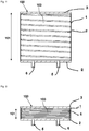
- the Figure 1 shows the principle of operation of a device according to the invention.
- the device has a reservoir 100 which has a rigid base 2 and a rigid cover 3 opposite the base 2.
- the base 2 and the cover 3 are connected to one another via a flexible, circumferential wall 1, so that said reservoir 100 is formed.
- the flexible wall 1 of the reservoir 100 is designed, for example, as a cylindrical tube made of thin plastic film.
- the tube 1 is closed at its ends by the rigid base 2 and a rigid cover 3.
- a spring 4 preferably in the form of a helical spring 4, is arranged in an interior 103 of the reservoir 100 and is pretensioned against the base and the cover so that it tries to move the base 2 and cover 3 apart.
- the bottom 2 and the lid 3 of the Reservoirs 100 are therefore opposite one another in the direction of movement 101 of the spring 4.
- the spring 4 is biased against the base 2 and the cover 3 in such a way that it is in the position shown in FIG Figure 1
- the fully expanded position shown (end position) is already compressed to preferably 50% to 70%, preferably 60% of its relaxed length.
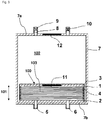
- the spring 4 is completely compressed in its initial position. Your spring travel is therefore in particular used to 50% to 70% or 60%.
- the spring 4 is preferably also designed so that in the fully compressed position (cf. Fig. 2 ) the maximum possible spring force then generates the desired negative pressure.
- the negative pressure is 50% to 70% or 60% of the desired value.
- the negative pressure does not change between zero and 100%, but only between zero and 50% to 70% or between zero and 60%.
- the coils of the spring 4 furthermore prevent the reservoir 100, in particular the flexible wall 1, from collapsing when the reservoir 100 is compressed.
- the device or the reservoir 100 has a first connection 5, via which drained fluid can be sucked into the reservoir 100, and a second connection 6 via which said fluid can be withdrawn from the reservoir 100.
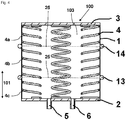
- FIG. 3 shows a further embodiment of a device according to the invention, in which the in the Figures 1 and 2 Reservoir 100 shown is arranged in a housing 7.
- the two connections 5 and 6 penetrate the housing 7 in this embodiment.
- the bottom 2 is connected to a wall 7b of the housing 7, whereas the cover 3 is movably arranged in an interior 102 of the housing 7.
- the housing 7 is also provided with a connection 8 in which a flow resistance 9 is arranged.
- valve 10 which, when opened, allows air to flow unhindered into the interior 102 of the housing 7 allowed, namely between the housing 7 and a wall 1, 3 of the reservoir 100 allowed.
- the device according to Fig. 3 preferably a magnet 11 which is arranged in the movable cover 3 of the reservoir 100, and a magnet 12 which is fixedly arranged in the wall 7a of the housing 7 opposite the cover 3.
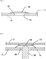
- the illustrated embodiment of the device or of the reservoir 100 uses a plurality of springs which are arranged between the edges of the base 2 and the cover 3.
- two expansion rings 13 and 14 are additionally preferably arranged on the circumferential wall 1, which prevent the collapse of the tubular reservoir 100, for example similar to a bellows or an accordion.
- one or more plates 25 can also be provided in the interior of the reservoir 100, which plates extend transversely to the springs 4 or to the direction of movement 101 and bear against the wall 1.
- Such plates 25 can be penetrated by the springs 4.
- the springs 4 can, however, also be divided accordingly, in which case the resulting spring sections 4a, 4b, 4c are supported on the then continuous plates 25.
- the plates 25 provided, for example, instead of the expanding rings 13, 14 are shown in FIG Figure 4 indicated with dashed lines.
- FIG. 5 in detail a possible arrangement for tensioning the device, which can be used in all embodiments with housing 7.
- housing 7a of the housing 7 opposite the cover 3 an opening or bore 15 is arranged.
- a movable disk 16 is arranged in the interior 102 of the housing 7 and is connected to the wall 7 a of the housing 7 by an elastic membrane 17 or a bellows 17. If, as in Fig. 6 shown, the user has a finger 18 or a If a suitable object is inserted into the opening 15, he or she can press the disk 16 against the cover 3 and thus tension the device or its spring (s) 4.
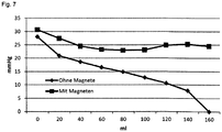
- FIG. 11 shows the course of the negative pressure in the reservoir 100 as a function of the volume sucked in by the device according to FIG Fig. 3 with and without magnets 11, 12.
Landscapes
- Health & Medical Sciences (AREA)
- Heart & Thoracic Surgery (AREA)
- Vascular Medicine (AREA)
- Engineering & Computer Science (AREA)
- Anesthesiology (AREA)
- Biomedical Technology (AREA)
- Hematology (AREA)
- Life Sciences & Earth Sciences (AREA)
- Animal Behavior & Ethology (AREA)
- General Health & Medical Sciences (AREA)
- Public Health (AREA)
- Veterinary Medicine (AREA)
- External Artificial Organs (AREA)
- Reciprocating Pumps (AREA)
Description
- Die Erfindung betrifft eine Einrichtung zur Drainage, insbesondere zur Drainage eines chronischen subduralen Hämatoms (CSH).
- Das Chronische Subdurale Hämatom ist einer Erkrankung, die typischerweise bei älteren Patienten durch ein traumatisches Ereignis ausgelöst wird. Es kommt zu einer Blutung unter der harten Hirnhaut (Dura) in den subduralen Raum (den Raum darunter). Die Blutung kommt meist unter dem Druck in dem Bluterguss (Hämatom) zum Stehen, es blutet aber in dem Maße, wie das Blut abgebaut wird, nach. Es handelt sich also um eine chronische Erkrankung, die nur chirurgisch beherrscht werden kann. Dazu wird der Schädel geöffnet, das Blut aus dem Bluterguss wird abgelassen oder je nach Größe auch ausgeräumt oder ausgewaschen. Nach diesem Eingriff besteht eine hohe Wahrscheinlichkeit des Nachblutens und des Wiederauftretens des Zustandes. Durch klinische Studien konnte belegt werden, dass die Wahrscheinlichkeit des Wiederauftretens signifikant kleiner ist, wenn nach dem chirurgischen Eingriff ein Drainagekatheter eingelegt wird, der über einige Tage weiteres Blut abdrainiert. Eine solche Drainage wird typischerweise schwerkraftinduziert angelegt, indem ein Auffangbehälter (Reservoir, Tropfkammer, Beutel) einige Zentimeter unter dem Niveau des Hämatoms angebracht wird, so dass unter hydrostatisch erzeugtem geringem Unterdruck das Blut und eventuelle Wundflüssigkeit abgeführt werden.
- Die Schwierigkeit dabei besteht darin, dass die Wundhöhle nicht vollständig mit Flüssigkeit gefüllt ist, so dass auch Luft angesaugt werden kann. Diese bildet dann im Schlauchsystem Blasen oder Schaum und die Schwerkraftdrainage kommt zum Erliegen.
- Es ist versucht worden, echte Saugdrainagen zu verwenden, bei denen entweder mechanisch durch federbelastete Balgen o. ä. oder durch Vakuumflaschen gesaugt wird. Unterdrücke in einer Größenordnung von mehr als -30 mmHg (-4 kPa) sind aber für das Hirn schädlich und nicht zulässig.
- Vakuumbehälter mit derart niedrigem Unterdruck saugen aber jeweils nur einen geringen Teil (weniger als 5%) Ihres Volumens, bevor das Vakuum erschöpft ist. Balgenkonstruktionen erzeugen konstruktionsbedingt einen über das Arbeitsvolumen bis auf Null abfallenden Unterdruck, so dass ebenfalls nicht das gesamte Volumen für die Drainage zur Verfügung steht.
- Weiterhin sind Produkte bekannt, bei denen zwei Platten, die mit einer schlauchförmigen Membran verbunden sind, durch eine oder mehrere Schraubenfedern auseinander gedrückt werden, so dass im Inneren ein Unterdruck entsteht. Auch solche Produkte erzeugen einen Unterdruck, der von seinem Maximalwert auf Null abfällt, wenn das Produkt so ausgelegt ist, dass die Federn in der Endlage vollständig entspannt sind. Es ist versucht worden, durch Vorspannung der Federn den Unterdruck in der Endlage nicht auf Null, sondern auf einen durch die Vorspannung definierten Wert, der ungleich Null ist, abfallen zu lassen. Die erreichbare Vorspannung ist aber aus konstruktiven Gründen begrenzt und die Änderung des Unterdruckes über den Arbeitsbereich ist immer noch zu groß.
- Ein weiteres Problem entsteht, wenn nach dem chirurgischen Eingriff ein Liquorleck auftritt. Das ist eine Situation, in der Hirnwasser (Liquor cerebrospinalis, kurz: Liquor) austritt. Bei unkontrollierter Saugdrainage, selbst mit niedrigem Druck, kann Liquor in größerer Menge angesaugt werden, was zu Schäden für den Patienten bis zum Tod führen kann.
- Die Schrift
WO 2007/0058851 A2 - Dabei wird gelehrt, dass eine Vorspannung durch ein Vorspannelement, wie beispielsweise eine mechanische Vorspannung (Feder, elastisch, etc.), eine pneumatische Vorspannung (Aufbringen von Luftdruck), eine elektrische Vorspannung (Elektromagnet oder motorisiertes Vorspannelement) oder dergleichen oder eine beliebige Kombination davon erzeugt wird, um den ausdehnbaren Behälter zu öffnen.
- Die Besonderheit dieser technischen Lösung besteht darin, dass die Vorspannung dem Behälter im Zustand des minimierten Volumens aufgeprägt wird, denn durch sie soll der Behälter expandieren.
-
EP 2 777 751 A2 offenbart ein Werkzeug umfassend einen Lokalisierer mit einer Mitte, die mit einer Rotorachse ausgerichtet ist, wenn sie über dem Ventil angeordnet ist. Der Lokalisierer ist ungefähr senkrecht zur Rotorachse. Ein Einstellelement ist in dem Lokalisierer angeordnet. Die Einstellvorrichtung passt in die Wand und hat einen Magneten mit einer magnetischen Achse, um den Rotor zu entriegeln. Eine einstellbare äußere Wand hat eine erste Positionsabmessung, die es dem Einstellelement erlaubt, sich um das Zentrum des Lokalisierers zu drehen und die magnetische Achse mit der Mitte auszurichten. Die einstellbare äußere Wand hat eine zweite Positionsabmessung weniger als die erste Dimension und die erste Positionsabmessung. Der Justierer kann sich seitlich, rotatorisch und orbital in dem Lokalisierer bewegen, der die magnetische Achse mit der Mitte falsch ausrichtet. Durch falsche Ausrichtung der Magnet- und Rotorachsen werden die Rotoren entriegelt und der Magnet behält den entriegelten Zustand bei, auch wenn die Achsen falsch ausgerichtet sind. -
DE 11 2012 005513 T5 offenbart eine medizinische Absaugvorrichtung und insbesondere eine medizinische Absaugvorrichtung mit einer Bodenplatte, einer Druckplatte, die in einem gewissen Abstand von der Bodenplatte angeordnet ist und ein Ablassloch definiert, das durch eine Öffnungs- / Schließeinrichtung geöffnet und geschlossen wird, eine Schraubenfeder, die zwischen der Bodenplatte und der Druckplatte installiert ist, eine Dichtungsmembran, die die Kanten der Bodenplatte und der Druckplatte verbindet und einen Aufnahmeraum definiert, der Körperflüssigkeit zwischen der Bodenplatte und der Druckplatte aufnehmen kann, und ein Drainagerohr, das mit der Druckplatte verbunden ist, um von dem Körper erzeugtes Körperfluid zu dem Aufnahmeraum zu leiten, und ein Rückschlagventil enthält, das es dem Fluid ermöglicht, nur in der Richtung von dem Körper zu dem Aufnahmeraum zu fließen, wobei der medizinische Aspirator die Wirkung hat, eine Kontamination der Körperflüssigkeit durch die Außenluft zu verhindern, die aus dem Körper extrahiert und in dem Aufnahmeraum gespeichert wird. - Nachteilig bei diesen technischen Lösungen eines Druckausgleichsventils ist, dass dieses Ventil einen Druckunterschied nur ausgleichen, aber nicht aufbauen kann.
- Aufgabe der Erfindung ist die Schaffung einer Einrichtung zur Drainage des chronischen subduralen Hämatoms unter Verwendung eines Reservoirs, das konstruktionsbedingt einen annähernd konstanten Unterdruck insbesondere in einer Größenordnung von unter 30 mmHg (4 kPa) erzeugt.
- Eine weitere Aufgabe der Erfindung besteht insbesondere darin, eine Einrichtung der genannten Art zu schaffen, bei der der Volumenstrom, also das pro Zeit abgesaugte Volumen, begrenzt ist.
- Dieses Problem wird durch eine Einrichtung mit den Merkmalen des Anspruchs 1 gelöst. Vorteilhafte Ausgestaltungen der Erfindung sind in den Unteransprüchen angegeben und werden nachfolgend beschrieben. Die nachfolgend beschriebenen Merkmale der Erfindung können in jeglicher sinnvoller Art und Weise miteinander kombiniert werden.
- Erfindungsgemäß wird das Problem durch die Kombination eines schlauchförmigen Reservoirs mit biegeweicher Wand und steifem Deckel und Boden mit wenigstens einer innen oder außen liegenden Feder gelöst. Die wenigstens eine Feder wird so angeordnet, dass sie Boden und Deckel auseinander drückt bzw. voneinander weg bewegen kann. Die wenigstens eine Feder ist hierbei vorzugsweise derart vorgespannt, dass sie nur über einen Teil ihres Federweges verformt wird, so dass ihre Kraft, und damit der von ihr erzeugte Unterdruck sich nur wenig ändert. Weiterhin ist erfindungsgemäß wenigstens eine Anordnung von einem oder mehreren Magneten vorhanden, die die Kennlinie der wenigstens einen Feder so kompensiert, dass die besagte Kraft annähernd konstant gehalten wird.
- Mit anderen Worten ist also die mindestens eine Feder gemäß einer Ausführungsform der Erfindung vorzugsweise so vorgespannt, dass der Weg zwischen der Anfangslage und einer durch die Länge des Reservoirs vorgegebenen Endlage der mindestens einen Feder nur einen Teil des gesamten Federweges der mindestens einen Feder ausmacht. Die besagte Länge des Reservoirs ist hierbei dessen maximale Ausdehnung in der Bewegungsrichtung der Feder. Weiterhin sind erfindungsgemäß ein oder mehrere Magnete vorgesehen, die so konfiguriert sind, dass sie - neben der Federkraft - eine zusätzliche Kraft auf das Reservoir ausüben, derart, dass eine resultierende, den Deckel und den Boden auseinanderdrückende Kraft über jenen Teil des Federweges im Wesentlichen konstant ist bzw. bevorzugt konstant ist. Hierbei ist eine Vielzahl an geeigneten Magnetanordnungen möglich, wobei besonders bevorzugte Anordnungen weiter unten angegeben sind.
- Im Wesentlichen konstant heißt hierbei, dass der Betrag der Kraft über jenen Teil des Federweges bevorzugt nicht mehr als 50%, bevorzugt nicht mehr als 40%, bevorzugt nicht mehr als 30%, bevorzugt nicht mehr als 20%, bevorzugt nicht mehr als 10%, bevorzugt nicht mehr als 5%, bevorzugt nicht mehr als 1% von dem Durchschnittsbetrag der Kraft über jenen Teil des Federweges abweicht.
- In einer alternativen Ausführungsform heißt "im Wesentlichen konstant", dass der Kraft ein Unterdruck im Reservoir entspricht, der über jenen Teil des Federweges der mindestens einen Feder zwischen Anfangs- und Endlage der mindestens einen Feder im Bereich von 20 bis 40 mmHg (2,67 bis 5,33 kPa) liegt, vorzugsweise in einem Bereich von 25 bis 35mmHg (3,33 bis 4,66 kPa), vorzugsweise in einem Bereich von 27 bis 33mmHg (3,60 bis 4,40 kPa), vorzugsweise in einem Bereich von 28 bis 32mmHg (3,73 bis 4,27 kPa), vorzugsweise in einem Bereich von 29 bis 31mmHg (3,87 bis 4,13 kPa). In einer weiteren Ausgestaltung der Erfindung gelten diese bevorzugten Druckbereiche ebenfalls, wobei hier immer die oberen Grenze durch 30mmHg (4 kPa) gebildet wird.
- In einer bevorzugten Ausführung der Erfindung ist das schlauchförmige Reservoir mit biegeweicher Wand und steifem Deckel und Boden mit wenigstens einer innenliegenden Feder in einem Gehäuse angeordnet. Vorzugsweise ist das schlauchförmige Reservoir mit einem oder mehreren Anschlüssen für je einen Schlauch versehen, wobei über jene Anschlüsse je ein Schlauch in Strömungsverbindung mit dem Reservoir bringbar ist.
- Jene Anschlüsse durchdringen bevorzugt eine Wand des Gehäuses und sind mit dieser und dem Reservoir dicht verbunden oder in diese mittels Dichtmitteln eingedichtet.
- Weiterhin ist gemäß einer Ausführungsform der Erfindung das Gehäuse mit wenigstens einem Anschluss versehen. Wenn der Anschluss in dem Gehäuse geöffnet ist, kann sich das schlauchförmige Reservoir frei ausdehnen und zusammenziehen. Ist der Anschluss geschlossen, wird das Ausdehnen und Zusammenziehen blockiert, da sich in einem Innenraum des Gehäuses, insbesondere zwischen einer Wand des Gehäuses und einer Wandung bzw. dem Deckel des schlauchförmigen Reservoirs ein Über- oder Unterdruck aufbaut, der die Bewegung der Wand des schlauchförmigen Reservoirs behindert.
- In einer bevorzugten Ausführung der Erfindung ist in dem Anschluss in dem Gehäuse eine Durchflussbegrenzung vorgesehen, z.B. in Form eines Strömungswiderstandes, z.B. einer semipermeablen Membran, einer Düse oder einer Lochplatte, welche den Abstrom von Umgebungsluft aus dem Raum zwischen der Gehäusewand und jener Wandung des schlauchförmigen Reservoirs begrenzt.
- In einer besonders bevorzugten Ausführung der Erfindung ist der Boden des schlauchförmigen Reservoirs mit einer (insbesondere unteren) Wand des Gehäuses form- kraft- oder stoffschlüssig so verbunden, dass bei Zusammenziehen oder Ausdehnen des schlauchförmigen Reservoirs der dem Boden in Bewegungsrichtung der mindestens einen Feder gegenüberliegende Deckel des Reservoirs eine relative Bewegung zum Gehäuse ausführt.
- Weiterhin ist gemäß einer Ausführungsform der Erfindung im oder am Deckel wenigstens ein Magnet angebracht. Weiterhin ist in der Wand des Gehäuses, die dem Deckel gegenüberliegt, wenigstens ein Magnet oder ein paramagnetischer, bevorzugt superparamagnetischer oder ferromagnetischer, Körper angebracht, welcher so orientiert ist, dass er bei Annäherung des Deckels an die gegenüberliegende Wand eine grösser werdende Anziehungskraft ausübt. Bei abnehmender Kraft der wenigstens einen Feder, wird also eine zunehmende Magnetkraft ausgeübt, welche die Abnahme der Federkraft ganz oder teilweise kompensiert. Weiterhin kann die Anordnung auch andersherum ausgeführt werden, d.h. ein etwaiger paramagnetischer, superparamagnetischer oder ferromagnetischer Körper auch am Deckel angeordnet sein und der mindestens Magnet an jener Wand des Gehäuses.
- Vorzugsweise wirken der oder die Magnete bzw. paramagnetischer, superparamagnetischer oder ferromagnetischer Körper so zusammen, dass eine resultierende, den Boden und den Deckel auseinander bewegende Kraft im Wesentlichen konstant ist, bevorzugt konstant ist (siehe auch oben).
- Zum Spannen der Einrichtung kann das Reservoir mittels einer Injektionsspritze o ä leergesaugt werden. In einer bevorzugten Ausführung der Erfindung wird die Einrichtung gespannt, indem der bewegliche Deckel von Hand gegen die Feder- und ggf. Magnetkraft bewegt wird.
- Insbesondere im Falle der Anordnung des Reservoirs in einem vorzugsweise hermetisch dichten Gehäuse (z.B. mit oben beschriebenen Strömungswiderstand zur Volumenstrombegrenzung) wird gemäß einer Ausführungsform der Erfindung eine Öffnung in dem Gehäuse vorgesehen, durch die z.B. ein Stab oder Ähnliches gegen die bewegliche Platte gedrückt wird, wobei der Stab gegen das Gehäuse in einer zylindrischen Führung durch eine Dichtung abgedichtet ist.
- In einer bevorzugten Ausführung der Erfindung ist eine Scheibe unter der Öffnung angebracht, die mit einem Balg oder einer elastischen Membran gegen das Gehäuse abgedichtet ist. Die Scheibe ist vorzugsweise vom Durchmesser her größer als die Öffnung, so dass sie in einer Ruheposition an einem umlaufenden Rand der Öffnung an der Innenwand des Gehäuses anliegen kann. Die Öffnung ist bevorzugt so dimensioniert, dass der Anwender einen Finger oder einen geeigneten Gegenstand durch die Öffnung stecken kann, wobei er oder sie die Scheibe von der Innenwand des Gehäuses weg gegen den beweglichen Deckel des Reservoirs drückt und damit die Einrichtung spannt.
- In einer weiteren bevorzugten Ausführungsform der Erfindung ist zum Spannen eine elastische Pumpkammer in oder an einer Wand des Gehäuses vorgesehen, die über ein Rückschlagventil mit der Atmosphäre verbunden ist und über ein weiteres Rückschlagventil mit einem Innenraum des Gehäuses. Die Rückschlagventile sind so orientiert, dass sie eine Strömung von der Atmosphäre in die elastische Pumpkammer und aus der Pumpkammer in den Innenraum des Gehäuses erlauben und eine Strömung in Gegenrichtung sperren. Wird die Pumpkammer betätigt, wird Luft in den Innenraum des Gehäuses gepumpt und durch den sich aufbauenden Druck das Reservoir zusammengedrückt (gespannt).
- Weiterhin ist gemäß einer Ausführungsform der Erfindung vorgesehen, dass die mindestens eine Feder eine Mehrzahl an Windungen aufweist und so an einer Peripherie des Deckels und des Bodens angeordnet ist, dass das Reservoir durch die Windungen der mindestens einen Feder gestützt wird.
- Weiterhin ist gemäß einer Ausführungsform der Erfindung vorgesehen, dass die Einrichtung zumindest ein Spreizelement aufweist, um ein Kollabieren der biegeweichen Wand des Reservoirs zu verhindern, insbesondere wenn der Deckel in Richtung auf den Boden bewegt wird. Bei diesem Spreizelement kann es sich z.B.um einen mit der Wand des Reservoirs verbundenen Ring handeln.
- Weiterhin ist gemäß einer Ausführungsform der Erfindung vorgesehen, dass das mindestens eine Spreizelement eine in einem Innenraum des Reservoirs angeordnete Platte ist, die sich vorzugsweise quer zur Bewegungsrichtung der mindestens einen Feder erstreckt.
- Weitere Merkmale und Vorteile der Erfindung sollen nachfolgend bei der Beschreibung von Ausführungsbeispielen anhand der Figuren erläutert werden. Es zeigen:
- Fig. 1
- eine geschnittene Ansicht einer erfindungsgemäßen Einrichtung,
- Fig. 2
- eine geschnittene Ansicht der Einrichtung gemäß
Figur 1 mit gespannter Feder, - Fig. 3
- eine geschnittene Ansicht einer weiteren erfindungsgemäßen Einrichtung,
- Fig. 4
- eine geschnittene Ansicht einer weiteren erfindungsgemäßen Einrichtung mit mehreren Federn,
- Fig. 5 - 6
- geschnittene Detailansichten einer Öffnung einer erfindungsgemäßen Einrichtung zum Spannen der Feder(n) der Einrichtung
- Fig. 7
- einen graphische Darstellung des Verlaufs des Unterdruckes [mmHg] über dem angesaugten Volumen [ml] der Einrichtung nach
Fig. 3 mit und ohne Magnete. - Die
Figur 1 zeigt die prinzipielle Funktionsweise einer erfindungsgemäßen Einrichtung. In der dargestellten Ausführung weist die Einrichtung ein Reservoir 100 auf, das einen starren Boden 2 und einen dem Boden 2 gegenüberliegenden starren Deckel 3 aufweist. Der Boden 2 und der Deckel 3 sind über eine biegeweiche, umlaufende Wand 1 miteinander verbunden, so dass das besagte Reservoir 100 gebildet wird. - Vorliegend ist die biegeweiche Wand 1 des Reservoirs 100 z.B. als ein zylindrischer Schlauch aus dünner Kunststofffolie ausgeführt. Der Schlauch 1 ist dabei an seinen Enden durch den starren Boden 2 und einen starren Deckel 3 verschlossen.
- Weiterhin ist in einem Innenraum 103 des Reservoirs 100 eine Feder 4, vorzugsweise in Form einer Schraubenfeder 4, angeordnet, die gegen den Boden und den Deckel vorgespannt ist, so dass sie versucht Boden 2 und Deckel 3 auseinander zu bewegen. Der Boden 2 und der Deckel 3 des Reservoirs 100 liegen also einander in der Bewegungsrichtung 101 der Feder 4 gegenüber.
- Die Feder 4 ist dabei derart gegen den Boden 2 und den Deckel 3 vorgespannt, dass sie in der in
Figur 1 gezeigten voll expandierten Position (Endlage) bereits auf vorzugsweise 50% bis 70%, vorzugsweise 60% ihrer entspannten Länge zusammengedrückt ist. In der in derFig. 2 gezeigten, zusammengedrückten Position des Reservoirs 100 bzw. der Feder 4 ist die Feder 4 in ihrer Anfangslage vollständig zusammengedrückt. Ihr Federweg ist also insbesondere zu 50% bis 70% bzw. zu 60% ausgenützt. - Die Feder 4 ist bevorzugt weiterhin so ausgelegt, dass in der vollständig zusammengedrückten Position (vgl.
Fig. 2 ) die dann maximal mögliche Federkraft den gewünschten Unterdruck erzeugt. In der inFig. 1 gezeigten vollständig expandierten Position beträgt der Unterdruck 50% bis 70% bzw. 60% des gewünschten Wertes. Der Unterdruck ändert sich also nicht zwischen Null und 100%, sondern nur zwischen Null und 50% bis 70% bzw. Null und 60%. Bei dieser Konstruktion verhindern die Windungen der Feder 4 weiterhin ein Kollabieren des Reservoirs 100, insbesondere der biegeweichen Wand 1, beim Zusammendrücken des Reservoirs 100. - Weiterhin weist die Einrichtung bzw. das Reservoir 100 einen ersten Anschluss 5 auf, über den abdrainiertes Fluid in das Reservoir 100 einsaugbar ist, sowie einen zweiten Anschluss 6 über den besagtes Fluid aus dem Reservoir 100 abziehbar ist.
-
Fig. 3 zeigt eine weitere Ausführungsform einer erfindungsgemäßen Einrichtung, bei der das in denFiguren 1 und 2 gezeigte Reservoir 100 in einem Gehäuse 7 angeordnet ist. - Die beiden Anschlüsse 5 und 6 durchdringen bei dieser Ausfuhrungsform das Gehäuse 7.
- Der Boden 2 ist mit einer Wand 7b des Gehäuses 7 verbunden, wohingegen der Deckel 3 beweglich in einem Innenraum 102 des Gehäuses 7 angeordnet ist.
- Das Gehäuse 7 ist weiterhin mit einem Anschluss 8 versehen, in welchem ein Strömungswiderstand 9 angeordnet ist.
- Weiterhin ist ein Ventil 10 vorhanden, welches, wenn geöffnet, das ungehinderte Einströmen von Luft in den Innenraum 102 des Gehäuses 7 erlaubt, und zwar zwischen Gehäuse 7 und einer Wandung 1, 3 des Reservoirs 100 erlaubt.
- Weiterhin weist die Einrichtung gemäß
Fig. 3 vorzugsweise einen Magneten 11 auf, der in dem beweglichen Deckel 3 des Reservoirs 100 angeordnet ist, sowie einen Magnet 12, welcher fest in der dem Deckel 3 gegenüberliegenden Wand 7a des Gehäuses 7 angeordnet ist. - Wenn sich die Feder 4 entspannt, ihre Kraft also abnimmt, nähert sich der Magnet 11 dem Magneten 12 an und übt eine zunehmende Kraft auf diesen aus, die die Abnahme der Federkraft kompensiert, so dass eine resultierende Kraft, die den Deckel 3 vom Boden 2 entfernt möglichst konstant ist (siehe oben).
- Die in der
Fig. 4 gezeigte Ausführung der Einrichtung bzw. des Reservoirs 100 verwendet mehrere Federn, die zwischen den Rändern des Bodens 2 und des Deckels 3 angeordnet sind. Bei dieser Ausführung sind zusätzlich vorzugsweise zwei Spreizringe 13 und 14 an der umlaufenden Wand 1 angeordnet, die das Kollabieren des schlauchförmigen Reservoirs 100, z.B. ähnlich wie bei einem Balg oder einer Ziehharmonika, verhindern. Anstelle derartiger Spreizringe können auch eine oder mehrere Platten 25 im Innenraum des Reservoirs 100 vorgesehen sein, die sich quer zu den Federn 4 bzw. zur Bewegungsrichtung 101 erstrecken und an der Wand 1 anliegen. Derartige Platten 25 können von den Federn 4 durchdrungen werden. Die Federn 4 können jedoch auch jeweils entsprechend geteilt sein, wobei dann die resultierenden Federabschnitte 4a, 4b, 4c sich an den dann durchgehenden Platten 25 abstützen. Die z.B. anstelle der Spreizringe 13, 14 vorgesehenen Platten 25 sind in derFigur 4 mit gestrichelten Linien angedeutet. - Die in der
Figur 4 gezeigte Konfiguration kann natürlich auch in einem Gehäuse 7 angeordnet werden, das z.B. wie oben beschrieben ausgeführt ist. - Weiterhin zeigt die
Figur 5 im Detail eine mögliche Anordnung zum Spannen der Einrichtung, die bei allen Ausführungsformen mit Gehäuse 7 verwendet werden kann. In der dem Deckel 3 gegenüberliegenden Wand 7a des Gehäuses 7 ist dabei eine Öffnung oder Bohrung 15 angeordnet. Eine bewegliche Scheibe 16 ist im Innenraum 102 des Gehäuses 7 angeordnet und mit der Wand 7a des Gehäuses 7 durch eine elastische Membran 17 oder einen Balg 17 verbunden. Wenn, wie inFig. 6 gezeigt, der Anwender oder die Anwenderin einen Finger 18 oder einen geeigneten Gegenstand in die Öffnung 15 steckt, kann er oder sie die Scheibe 16 gegen den Deckel 3 drücken und damit die Einrichtung bzw. deren Feder(n) 4 spannen. - Schließlich zeigt
Fig. 7 zeigt den Verlauf des Unterdruckes im Reservoir 100 in Abhängigkeit vom angesaugten Volumen der Einrichtung gemäßFig. 3 mit und ohne Magnete 11, 12.
Claims (18)
- Einrichtung zur Drainage, mit:- einem schlauchförmigen Reservoir (100) aufweisend eine biegeweiche Wand (1) sowie einen steifen Deckel (3) und einen steifen Boden (2), und- zumindest einer Feder (4), welche eine den Deckel (3) und den Boden (2) auseinanderdrückende Kraft ausübt, wobei der Deckel (3) in Richtung auf den Boden (2) bewegbar ist, um die Feder in eine Anfangslage zu bringen,dadurch gekennzeichnet,
dass die Einrichtung einen oder mehrere Magnete (11, 12) aufweist, die so konfiguriert sind, dass sie eine zusätzliche Kraft auf das Reservoir (100) ausüben, derart, dass eine resultierende, den Deckel (3) und den Boden (2) auseinanderdrückende Kraft über jenen Teil des Federweges nicht mehr als 50%, 40%, 30%, 20%, 10%, 5%, oder 1% von dem Durchschnittsbetrag der Kraft über jenen Teil des Federweges abweicht oder der Kraft ein Unterdruck im Reservoir entspricht, der über jenen Teil des Federweges der Feder zwischen Anfangs- und Endlage der Feder im Bereich von 20 bis 40 mmHg (2,67 bis 5,33 kPa) liegt. - Einrichtung nach Anspruch 1, dadurch gekennzeichnet, dass die mindestens eine Feder (4) so vorgespannt ist, dass der Weg zwischen der Anfangslage und einer durch die Länge des Reservoirs (100) vorgegebenen Endlage der mindestens einen Feder (4) nur einen Teil des gesamten Federweges der mindestens einen Feder (4) ausmacht.
- Einrichtung nach Anspruch 1 oder 2, dadurch gekennzeichnet, dass das schlauchförmige Reservoir (100) zumindest einen Anschluss (5, 6) zum Anschließen eines Schlauches aufweist.
- Einrichtung nach Anspruch 3, dadurch gekennzeichnet, dass das Reservoir (100) in einem Gehäuse (7) der Einrichtung angeordnet ist, und dass der mindestens eine Anschluss (5, 6) das Gehäuse (7) durchdringt und dicht mit dem Gehäuse (7) und dem Reservoir (100) verbunden ist oder mittels Dichtmitteln in diese eingedichtet ist.
- Einrichtung nach Anspruch 4, dadurch gekennzeichnet, dass das Gehäuse (7) zumindest einen Anschluss (8) aufweist, über den Umgebungsluft in einen Innenraum (102) des Gehäuses (7) zwischen einer Wand (7a) des Gehäuses (7) und einer Wandung (3) des Reservoirs (100) ein- und auslassbar ist.
- Einrichtung nach Anspruch 5, dadurch gekennzeichnet, dass in dem mindestens einen Anschluss (8) ein Strömungswiderstand (9) angeordnet ist, welcher den Volumenstrom der Umgebungsluft begrenzt.
- Einrichtung nach Anspruch 6, dadurch gekennzeichnet, dass der Strömungswiderstand (9) durch eines der folgenden Element gebildet ist:- eine Düse,- ein Element, das aus einer Mehrzahl von Düsen besteht,- ein poröses Element,- eine Membran, die eine oder eine Mehrzahl an Durchgangsöffnungen aufweist,- eine Membran, die aus einem gasdurchlässigen Werkstoff besteht oder einen gasdurchlässigen Werkstoff aufweist,- eine Membran, die aus Silikonkautschuk besteht oder Silikonkautschuk aufweist.
- Einrichtung nach einem der vorhergehenden Ansprüche, dadurch gekennzeichnet, dass der Boden (2) des Reservoirs (100) fest mit einer Wand (7b) Gehäuses (7) verbunden ist und der Deckel (3) bezüglich des Gehäuses (7) bewegbar im Gehäuse (7) angeordnet ist.
- Einrichtung nach Anspruch 8, dadurch gekennzeichnet, dass am Deckel (3) zumindest ein Magnet (11) angeordnet ist, und wobei an einer dem Deckel (3) gegenüberliegenden Wand (7a) des Gehäuses (7) zumindest ein weiterer Magnet (12) angeordnet ist, wobei der mindestens eine Magnet (11) und der mindestens eine weitere Magnet (12) so orientiert sind, dass sie sich gegenseitig anziehen.
- Einrichtung nach Anspruch 8, dadurch gekennzeichnet, dass am Deckel (3) zumindest ein Magnet (11) angeordnet ist, und wobei an einer dem Deckel (3) gegenüberliegenden Wand (7a) des Gehäuses (7) zumindest ein Körper aus einem magnetischen, paramagnetischen, superparamagnetischen oder ferromagnetischen Material angeordnet ist, wobei zwischen dem mindestens einen Magneten (11) und dem mindestens einen Körper (12) eine Anziehungskraft besteht.
- Einrichtung nach Anspruch 8, dadurch gekennzeichnet, dass am Deckel (3) zumindest ein Körper (11) aus einem magnetischen, paramagnetischen, superparamagnetischen oder ferromagnetischen Material angeordnet ist, und wobei an einer dem Deckel (3) gegenüberliegenden Wand (7a) des Gehäuses (7), zumindest ein Magnet (12) angeordnet ist, wobei zwischen dem mindestens einen Magneten (11) und dem mindestens einen Körper (12) eine Anziehungskraft besteht.
- Einrichtung nach einem der vorhergehenden Ansprüche, dadurch gekennzeichnet, dass die mindestens eine Feder (4) eine Mehrzahl an Windungen (40) aufweist und so an einer Peripherie des Deckels (3) und des Bodens (2) angeordnet ist, dass das Reservoir (100) durch die Windungen (40) der mindestens einen Feder (4) gestützt wird.
- Einrichtung nach einem der vorhergehenden Ansprüche, dadurch gekennzeichnet, dass die Einrichtung zumindest ein Spreizelement (13, 14) zum Stützen des Reservoirs (100) aufweist.
- Einrichtung nach Anspruch 13, dadurch gekennzeichnet, dass das mindestens eine Spreizelement (13, 14) ein mit der Wand (1) des Reservoirs (100) verbundener Ring ist.
- Einrichtung nach Anspruch 13, dadurch gekennzeichnet, dass das mindestens eine Spreizelement eine in einem Innenraum (103) des Reservoirs (100) angeordnete Platte (25) ist.
- Einrichtung nach einem der vorhergehenden Ansprüche, dadurch gekennzeichnet, dass in einer dem Deckel (3) gegenüberliegenden Wand (7a) des Gehäuses (7) eine Öffnung (15) angebracht ist.
- Einrichtung nach Anspruch 16, dadurch gekennzeichnet, dass die Einrichtung eine bewegliche Scheibe (16) aufweist, die in einem Innenraum (102) des Gehäuses (7) angeordnet ist und der Öffnung (15) gegenüberliegt, wobei die Scheibe (16) zur Abdichtung des Gehäuses über eine Membran (17) oder einen Balg (17) mit dem Gehäuse (7) verbunden ist, so dass sie zum Spannen der mindestens einen Feder (4) manuell gegen den Deckel (3) drückbar ist.
- Einrichtung nach einem der vorhergehenden Ansprüche, dadurch gekennzeichnet, dass eine elastische Pumpkammer in oder an der der Wand des Gehäuses vorgesehen ist, die über ein Rückschlagventil mit der Atmosphäre verbunden ist und über ein weiteres Rückschlagventil mit einem Innenraum des Gehäuses derart verbunden ist, dass die Rückschlagventile Strömung von der Atmosphäre in die elastische Pumpkammer und aus der Pumpkammer in den Innenraum des Gehäuses erlauben und Strömung in Gegenrichtung sperren.
Priority Applications (1)
| Application Number | Priority Date | Filing Date | Title |
|---|---|---|---|
| PL16726764T PL3302599T3 (pl) | 2015-06-02 | 2016-04-18 | Urządzenie do drenażu, w szczególności do drenażu przewlekłego krwiaka podtwardówkowego |
Applications Claiming Priority (2)
| Application Number | Priority Date | Filing Date | Title |
|---|---|---|---|
| DE102015108754.5A DE102015108754B8 (de) | 2015-06-02 | 2015-06-02 | Einrichtung zur Drainage, insbesondere zur Drainage eines chronischen subduralen Hämatoms |
| PCT/DE2016/100183 WO2016192705A1 (de) | 2015-06-02 | 2016-04-18 | Einrichtung zur drainage, insbesondere zur drainage eines chronischen subduralen hämatoms |
Publications (2)
| Publication Number | Publication Date |
|---|---|
| EP3302599A1 EP3302599A1 (de) | 2018-04-11 |
| EP3302599B1 true EP3302599B1 (de) | 2021-09-22 |
Family
ID=56097952
Family Applications (1)
| Application Number | Title | Priority Date | Filing Date |
|---|---|---|---|
| EP16726764.0A Active EP3302599B1 (de) | 2015-06-02 | 2016-04-18 | Einrichtung zur drainage, insbesondere zur drainage eines chronischen subduralen hämatoms |
Country Status (10)
| Country | Link |
|---|---|
| US (1) | US11065370B2 (de) |
| EP (1) | EP3302599B1 (de) |
| JP (1) | JP6774431B2 (de) |
| CN (1) | CN107666917B (de) |
| DE (1) | DE102015108754B8 (de) |
| ES (1) | ES2899223T3 (de) |
| HU (1) | HUE056758T2 (de) |
| PL (1) | PL3302599T3 (de) |
| PT (1) | PT3302599T (de) |
| WO (1) | WO2016192705A1 (de) |
Families Citing this family (3)
| Publication number | Priority date | Publication date | Assignee | Title |
|---|---|---|---|---|
| CN108969815B (zh) * | 2018-08-03 | 2020-11-03 | 吴联籽 | 一种用于腹部外科手术后的肛管排气装置 |
| NL2023563B1 (en) * | 2019-07-24 | 2021-02-10 | Heineken Supply Chain Bv | Pressure regulating system for a beverage container and beverage container provided therewith |
| CN111617325A (zh) * | 2020-05-28 | 2020-09-04 | 西安市儿童医院 | 基于胃肠、胸腹腔、及术后部位的医用减压引流装置 |
Family Cites Families (27)
| Publication number | Priority date | Publication date | Assignee | Title |
|---|---|---|---|---|
| NL95211C (de) * | 1956-03-02 | 1900-01-01 | ||
| US3115138A (en) * | 1960-07-14 | 1963-12-24 | Mcelvenny | Evacuator |
| US4141361A (en) * | 1970-02-09 | 1979-02-27 | Snyder Manufacturing Co., Incorporated | Evacuator |
| US3779243A (en) * | 1971-10-15 | 1973-12-18 | J Tussey | Contamination free surgical evacuator |
| US3939830A (en) * | 1975-03-10 | 1976-02-24 | Da Costa Harry | Manually operable dechoking and resuscitating device |
| US3991763A (en) * | 1975-04-17 | 1976-11-16 | Arbrook, Inc. | Surgical evacuator |
| US4278089A (en) * | 1978-11-09 | 1981-07-14 | Howmedica, Inc. | Wound drainage device |
| US4429693A (en) * | 1980-09-16 | 1984-02-07 | Blake L W | Surgical fluid evacuator |
| US4578060A (en) * | 1983-07-20 | 1986-03-25 | Howmedica, Inc. | Wound drainage device |
| US4957487A (en) * | 1988-12-30 | 1990-09-18 | Baylor College Of Medicine | External male urinary catheter and collection system |
| IL93045A (en) * | 1990-01-12 | 1995-01-24 | Rosenberg Lior | A particularly usable vacuum device for removing wound fluid |
| JPH0836421A (ja) * | 1994-07-22 | 1996-02-06 | Fujikura Rubber Ltd | 磁石式減圧弁 |
| US5665070A (en) * | 1995-01-19 | 1997-09-09 | I-Flow Corporation | Infusion pump with magnetic bag compression |
| US5628305A (en) * | 1995-09-27 | 1997-05-13 | Richard J. Melker | Universal ventilation device |
| JPH09315593A (ja) * | 1996-05-24 | 1997-12-09 | Ricoh Co Ltd | 給紙用支持装置 |
| US6923799B1 (en) * | 1999-06-04 | 2005-08-02 | Wilson T. Asfora | Subdural evacuating port system |
| US7815616B2 (en) * | 2002-09-16 | 2010-10-19 | Boehringer Technologies, L.P. | Device for treating a wound |
| JP5192375B2 (ja) * | 2005-07-05 | 2013-05-08 | シー・アール・バード・インコーポレーテッド | 多機能モジュール式集尿システム |
| US20110238022A1 (en) * | 2010-03-24 | 2011-09-29 | Shayna Massi | Corporeal drainage system |
| US8753322B2 (en) * | 2010-08-10 | 2014-06-17 | Spiracur Inc. | Controlled negative pressure apparatus and alarm mechanism |
| US8795246B2 (en) * | 2010-08-10 | 2014-08-05 | Spiracur Inc. | Alarm system |
| CN102228722A (zh) * | 2011-06-13 | 2011-11-02 | 天津怡美医疗器械有限公司 | 预置负压与重力负压自动交替引流器 |
| KR101367004B1 (ko) | 2011-12-30 | 2014-02-24 | 김용찬 | 의료용 흡인기 |
| CN203303389U (zh) * | 2012-08-23 | 2013-11-27 | 程秀巧 | 一种医用引流器 |
| US9242077B2 (en) | 2013-03-12 | 2016-01-26 | DePuy Synthes Products, Inc. | Dynamic adjustment tool for programming an implantable valve |
| WO2015003249A1 (en) * | 2013-07-12 | 2015-01-15 | Trudell Medical International | Huff cough simulation device |
| US20150300124A1 (en) * | 2015-07-07 | 2015-10-22 | Tejas Research & Engineering, Llc | Surface Controlled Downhole Valve with Supplemental Spring Closing Force for Ultra Deep Wells |
-
2015
- 2015-06-02 DE DE102015108754.5A patent/DE102015108754B8/de active Active
-
2016
- 2016-04-18 PT PT167267640T patent/PT3302599T/pt unknown
- 2016-04-18 CN CN201680032464.8A patent/CN107666917B/zh active Active
- 2016-04-18 HU HUE16726764A patent/HUE056758T2/hu unknown
- 2016-04-18 WO PCT/DE2016/100183 patent/WO2016192705A1/de not_active Ceased
- 2016-04-18 JP JP2017562059A patent/JP6774431B2/ja active Active
- 2016-04-18 ES ES16726764T patent/ES2899223T3/es active Active
- 2016-04-18 PL PL16726764T patent/PL3302599T3/pl unknown
- 2016-04-18 EP EP16726764.0A patent/EP3302599B1/de active Active
- 2016-04-18 US US15/579,017 patent/US11065370B2/en active Active
Also Published As
| Publication number | Publication date |
|---|---|
| HUE056758T2 (hu) | 2022-03-28 |
| EP3302599A1 (de) | 2018-04-11 |
| US11065370B2 (en) | 2021-07-20 |
| DE102015108754B3 (de) | 2016-09-08 |
| WO2016192705A1 (de) | 2016-12-08 |
| CN107666917B (zh) | 2021-11-09 |
| JP6774431B2 (ja) | 2020-10-21 |
| JP2018524048A (ja) | 2018-08-30 |
| CN107666917A (zh) | 2018-02-06 |
| ES2899223T3 (es) | 2022-03-10 |
| US20180140754A1 (en) | 2018-05-24 |
| PL3302599T3 (pl) | 2022-02-07 |
| DE102015108754B8 (de) | 2018-03-22 |
| PT3302599T (pt) | 2021-11-03 |
Similar Documents
| Publication | Publication Date | Title |
|---|---|---|
| EP0218785B1 (de) | Gerät zur Aufnahme und Reinfusion von Blut | |
| EP3113806B1 (de) | Katheter zum gerichteten leiten einer körperflüssigkeit | |
| DE3441891C2 (de) | ||
| DE69011631T2 (de) | Mikropumpe. | |
| EP3188774B1 (de) | Verfahren zur bestimmung eines systemkompressibilitätswertes eines medizinischen membranpumpenantriebs | |
| CH709183A1 (de) | Thoraxdrainagevorrichtung. | |
| WO1988005319A1 (fr) | Dispositif pour aspirer les fluides des blessures | |
| DE102007013492A1 (de) | Expansions-Fingergreifer | |
| DE2103187B2 (de) | Medizinische Wegwerfvorrichtung zum Absaugen von Flüssigkeiten | |
| WO2010121741A1 (de) | Ventilvorrichtung, ventileinsatz, externe funktionseinrichtung, behandlungsvorrichtung sowie verfahren | |
| DE102015108754B3 (de) | Einrichtung zur Drainage, insbesondere zur Drainage eines chronischen subduralen Hämatoms | |
| WO1999022787A1 (de) | Infusionsgerät mit tropfkammer und schlauchklemme | |
| DE112005001566T5 (de) | Einführungseinrichtung für endoluminale Eingriffe | |
| WO1989002764A1 (fr) | Agencement de clapet antiretour | |
| EP2885035B1 (de) | Einweg-ventileinrichtung | |
| EP2701599B1 (de) | Fluidhandhabungsvorrichtung mit Federmechanismus | |
| EP4058699A1 (de) | Schwimmerventil, druckluftsystem mit einem schwimmerventil und trockner für ein druckluftsystem mit einem schwimmerventil | |
| WO1980002506A1 (fr) | Aiguille pour un dispositif de perfusion | |
| DE102005003516B3 (de) | Blutentnahmereservoir | |
| DE69933308T2 (de) | Autotransfusionsbeutel mit hoher übertragungsrate | |
| DE202016100155U1 (de) | Unterdruckbehältnis | |
| DE3229253A1 (de) | Vakuumbetriebene pulsationspumpe | |
| DE102018121173A1 (de) | Drainagevorrichtung und Drainageset | |
| DE102004054496B4 (de) | Drainagekammer zur Aufnahme von Körperfluiden, insbesondere von Liquor | |
| WO2020043817A1 (de) | Drainagevorrichtung und drainageset |
Legal Events
| Date | Code | Title | Description |
|---|---|---|---|
| STAA | Information on the status of an ep patent application or granted ep patent |
Free format text: STATUS: THE INTERNATIONAL PUBLICATION HAS BEEN MADE |
|
| PUAI | Public reference made under article 153(3) epc to a published international application that has entered the european phase |
Free format text: ORIGINAL CODE: 0009012 |
|
| STAA | Information on the status of an ep patent application or granted ep patent |
Free format text: STATUS: REQUEST FOR EXAMINATION WAS MADE |
|
| 17P | Request for examination filed |
Effective date: 20171108 |
|
| AK | Designated contracting states |
Kind code of ref document: A1 Designated state(s): AL AT BE BG CH CY CZ DE DK EE ES FI FR GB GR HR HU IE IS IT LI LT LU LV MC MK MT NL NO PL PT RO RS SE SI SK SM TR |
|
| AX | Request for extension of the european patent |
Extension state: BA ME |
|
| DAV | Request for validation of the european patent (deleted) | ||
| DAX | Request for extension of the european patent (deleted) | ||
| GRAP | Despatch of communication of intention to grant a patent |
Free format text: ORIGINAL CODE: EPIDOSNIGR1 |
|
| STAA | Information on the status of an ep patent application or granted ep patent |
Free format text: STATUS: GRANT OF PATENT IS INTENDED |
|
| INTG | Intention to grant announced |
Effective date: 20210701 |
|
| RIN1 | Information on inventor provided before grant (corrected) |
Inventor name: SPIEGELBERG, ANDREAS |
|
| GRAS | Grant fee paid |
Free format text: ORIGINAL CODE: EPIDOSNIGR3 |
|
| GRAA | (expected) grant |
Free format text: ORIGINAL CODE: 0009210 |
|
| STAA | Information on the status of an ep patent application or granted ep patent |
Free format text: STATUS: THE PATENT HAS BEEN GRANTED |
|
| AK | Designated contracting states |
Kind code of ref document: B1 Designated state(s): AL AT BE BG CH CY CZ DE DK EE ES FI FR GB GR HR HU IE IS IT LI LT LU LV MC MK MT NL NO PL PT RO RS SE SI SK SM TR |
|
| REG | Reference to a national code |
Ref country code: GB Ref legal event code: FG4D Free format text: NOT ENGLISH |
|
| REG | Reference to a national code |
Ref country code: DE Ref legal event code: R096 Ref document number: 502016013875 Country of ref document: DE |
|
| REG | Reference to a national code |
Ref country code: IE Ref legal event code: FG4D Free format text: LANGUAGE OF EP DOCUMENT: GERMAN |
|
| REG | Reference to a national code |
Ref country code: CH Ref legal event code: EP Ref country code: AT Ref legal event code: REF Ref document number: 1431803 Country of ref document: AT Kind code of ref document: T Effective date: 20211015 |
|
| REG | Reference to a national code |
Ref country code: PT Ref legal event code: SC4A Ref document number: 3302599 Country of ref document: PT Date of ref document: 20211103 Kind code of ref document: T Free format text: AVAILABILITY OF NATIONAL TRANSLATION Effective date: 20211026 |
|
| REG | Reference to a national code |
Ref country code: NL Ref legal event code: FP |
|
| REG | Reference to a national code |
Ref country code: SE Ref legal event code: TRGR |
|
| REG | Reference to a national code |
Ref country code: LT Ref legal event code: MG9D |
|
| PG25 | Lapsed in a contracting state [announced via postgrant information from national office to epo] |
Ref country code: LT Free format text: LAPSE BECAUSE OF FAILURE TO SUBMIT A TRANSLATION OF THE DESCRIPTION OR TO PAY THE FEE WITHIN THE PRESCRIBED TIME-LIMIT Effective date: 20210922 Ref country code: BG Free format text: LAPSE BECAUSE OF FAILURE TO SUBMIT A TRANSLATION OF THE DESCRIPTION OR TO PAY THE FEE WITHIN THE PRESCRIBED TIME-LIMIT Effective date: 20211222 Ref country code: FI Free format text: LAPSE BECAUSE OF FAILURE TO SUBMIT A TRANSLATION OF THE DESCRIPTION OR TO PAY THE FEE WITHIN THE PRESCRIBED TIME-LIMIT Effective date: 20210922 Ref country code: HR Free format text: LAPSE BECAUSE OF FAILURE TO SUBMIT A TRANSLATION OF THE DESCRIPTION OR TO PAY THE FEE WITHIN THE PRESCRIBED TIME-LIMIT Effective date: 20210922 Ref country code: NO Free format text: LAPSE BECAUSE OF FAILURE TO SUBMIT A TRANSLATION OF THE DESCRIPTION OR TO PAY THE FEE WITHIN THE PRESCRIBED TIME-LIMIT Effective date: 20211222 Ref country code: RS Free format text: LAPSE BECAUSE OF FAILURE TO SUBMIT A TRANSLATION OF THE DESCRIPTION OR TO PAY THE FEE WITHIN THE PRESCRIBED TIME-LIMIT Effective date: 20210922 |
|
| PG25 | Lapsed in a contracting state [announced via postgrant information from national office to epo] |
Ref country code: LV Free format text: LAPSE BECAUSE OF FAILURE TO SUBMIT A TRANSLATION OF THE DESCRIPTION OR TO PAY THE FEE WITHIN THE PRESCRIBED TIME-LIMIT Effective date: 20210922 Ref country code: GR Free format text: LAPSE BECAUSE OF FAILURE TO SUBMIT A TRANSLATION OF THE DESCRIPTION OR TO PAY THE FEE WITHIN THE PRESCRIBED TIME-LIMIT Effective date: 20211223 |
|
| REG | Reference to a national code |
Ref country code: ES Ref legal event code: FG2A Ref document number: 2899223 Country of ref document: ES Kind code of ref document: T3 Effective date: 20220310 |
|
| REG | Reference to a national code |
Ref country code: HU Ref legal event code: AG4A Ref document number: E056758 Country of ref document: HU |
|
| PG25 | Lapsed in a contracting state [announced via postgrant information from national office to epo] |
Ref country code: IS Free format text: LAPSE BECAUSE OF FAILURE TO SUBMIT A TRANSLATION OF THE DESCRIPTION OR TO PAY THE FEE WITHIN THE PRESCRIBED TIME-LIMIT Effective date: 20220122 Ref country code: SK Free format text: LAPSE BECAUSE OF FAILURE TO SUBMIT A TRANSLATION OF THE DESCRIPTION OR TO PAY THE FEE WITHIN THE PRESCRIBED TIME-LIMIT Effective date: 20210922 Ref country code: RO Free format text: LAPSE BECAUSE OF FAILURE TO SUBMIT A TRANSLATION OF THE DESCRIPTION OR TO PAY THE FEE WITHIN THE PRESCRIBED TIME-LIMIT Effective date: 20210922 Ref country code: EE Free format text: LAPSE BECAUSE OF FAILURE TO SUBMIT A TRANSLATION OF THE DESCRIPTION OR TO PAY THE FEE WITHIN THE PRESCRIBED TIME-LIMIT Effective date: 20210922 Ref country code: CZ Free format text: LAPSE BECAUSE OF FAILURE TO SUBMIT A TRANSLATION OF THE DESCRIPTION OR TO PAY THE FEE WITHIN THE PRESCRIBED TIME-LIMIT Effective date: 20210922 Ref country code: AL Free format text: LAPSE BECAUSE OF FAILURE TO SUBMIT A TRANSLATION OF THE DESCRIPTION OR TO PAY THE FEE WITHIN THE PRESCRIBED TIME-LIMIT Effective date: 20210922 |
|
| REG | Reference to a national code |
Ref country code: DE Ref legal event code: R097 Ref document number: 502016013875 Country of ref document: DE |
|
| PG25 | Lapsed in a contracting state [announced via postgrant information from national office to epo] |
Ref country code: DK Free format text: LAPSE BECAUSE OF FAILURE TO SUBMIT A TRANSLATION OF THE DESCRIPTION OR TO PAY THE FEE WITHIN THE PRESCRIBED TIME-LIMIT Effective date: 20210922 |
|
| PLBE | No opposition filed within time limit |
Free format text: ORIGINAL CODE: 0009261 |
|
| STAA | Information on the status of an ep patent application or granted ep patent |
Free format text: STATUS: NO OPPOSITION FILED WITHIN TIME LIMIT |
|
| 26N | No opposition filed |
Effective date: 20220623 |
|
| PG25 | Lapsed in a contracting state [announced via postgrant information from national office to epo] |
Ref country code: SI Free format text: LAPSE BECAUSE OF FAILURE TO SUBMIT A TRANSLATION OF THE DESCRIPTION OR TO PAY THE FEE WITHIN THE PRESCRIBED TIME-LIMIT Effective date: 20210922 |
|
| REG | Reference to a national code |
Ref country code: BE Ref legal event code: MM Effective date: 20220430 |
|
| PG25 | Lapsed in a contracting state [announced via postgrant information from national office to epo] |
Ref country code: MC Free format text: LAPSE BECAUSE OF FAILURE TO SUBMIT A TRANSLATION OF THE DESCRIPTION OR TO PAY THE FEE WITHIN THE PRESCRIBED TIME-LIMIT Effective date: 20210922 Ref country code: LU Free format text: LAPSE BECAUSE OF NON-PAYMENT OF DUE FEES Effective date: 20220418 |
|
| PG25 | Lapsed in a contracting state [announced via postgrant information from national office to epo] |
Ref country code: BE Free format text: LAPSE BECAUSE OF NON-PAYMENT OF DUE FEES Effective date: 20220430 |
|
| PG25 | Lapsed in a contracting state [announced via postgrant information from national office to epo] |
Ref country code: IE Free format text: LAPSE BECAUSE OF NON-PAYMENT OF DUE FEES Effective date: 20220418 |
|
| PGFP | Annual fee paid to national office [announced via postgrant information from national office to epo] |
Ref country code: TR Payment date: 20230306 Year of fee payment: 8 |
|
| PG25 | Lapsed in a contracting state [announced via postgrant information from national office to epo] |
Ref country code: SM Free format text: LAPSE BECAUSE OF FAILURE TO SUBMIT A TRANSLATION OF THE DESCRIPTION OR TO PAY THE FEE WITHIN THE PRESCRIBED TIME-LIMIT Effective date: 20210922 Ref country code: MK Free format text: LAPSE BECAUSE OF FAILURE TO SUBMIT A TRANSLATION OF THE DESCRIPTION OR TO PAY THE FEE WITHIN THE PRESCRIBED TIME-LIMIT Effective date: 20210922 Ref country code: CY Free format text: LAPSE BECAUSE OF FAILURE TO SUBMIT A TRANSLATION OF THE DESCRIPTION OR TO PAY THE FEE WITHIN THE PRESCRIBED TIME-LIMIT Effective date: 20210922 |
|
| PG25 | Lapsed in a contracting state [announced via postgrant information from national office to epo] |
Ref country code: MT Free format text: LAPSE BECAUSE OF FAILURE TO SUBMIT A TRANSLATION OF THE DESCRIPTION OR TO PAY THE FEE WITHIN THE PRESCRIBED TIME-LIMIT Effective date: 20210922 |
|
| PGFP | Annual fee paid to national office [announced via postgrant information from national office to epo] |
Ref country code: NL Payment date: 20250424 Year of fee payment: 10 |
|
| PGFP | Annual fee paid to national office [announced via postgrant information from national office to epo] |
Ref country code: DE Payment date: 20250423 Year of fee payment: 10 |
|
| PGFP | Annual fee paid to national office [announced via postgrant information from national office to epo] |
Ref country code: ES Payment date: 20250502 Year of fee payment: 10 |
|
| PGFP | Annual fee paid to national office [announced via postgrant information from national office to epo] |
Ref country code: HU Payment date: 20250425 Year of fee payment: 10 |
|
| PGFP | Annual fee paid to national office [announced via postgrant information from national office to epo] |
Ref country code: IT Payment date: 20250424 Year of fee payment: 10 |
|
| PGFP | Annual fee paid to national office [announced via postgrant information from national office to epo] |
Ref country code: FR Payment date: 20250430 Year of fee payment: 10 |
|
| PGFP | Annual fee paid to national office [announced via postgrant information from national office to epo] |
Ref country code: CH Payment date: 20250501 Year of fee payment: 10 |
|
| PGFP | Annual fee paid to national office [announced via postgrant information from national office to epo] |
Ref country code: AT Payment date: 20250423 Year of fee payment: 10 |
|
| PGFP | Annual fee paid to national office [announced via postgrant information from national office to epo] |
Ref country code: SE Payment date: 20260324 Year of fee payment: 11 |
|
| PGFP | Annual fee paid to national office [announced via postgrant information from national office to epo] |
Ref country code: GB Payment date: 20260325 Year of fee payment: 11 |
|
| PGFP | Annual fee paid to national office [announced via postgrant information from national office to epo] |
Ref country code: PT Payment date: 20260309 Year of fee payment: 11 |
|
| PGFP | Annual fee paid to national office [announced via postgrant information from national office to epo] |
Ref country code: PL Payment date: 20260316 Year of fee payment: 11 |
|
| REG | Reference to a national code |
Ref country code: CH Ref legal event code: U11 Free format text: ST27 STATUS EVENT CODE: U-0-0-U10-U11 (AS PROVIDED BY THE NATIONAL OFFICE) Effective date: 20260501 |