EP3302378B1 - Intrauterine device with a restricted upward movement of a string - Google Patents
Intrauterine device with a restricted upward movement of a string Download PDFInfo
- Publication number
- EP3302378B1 EP3302378B1 EP15894050.2A EP15894050A EP3302378B1 EP 3302378 B1 EP3302378 B1 EP 3302378B1 EP 15894050 A EP15894050 A EP 15894050A EP 3302378 B1 EP3302378 B1 EP 3302378B1
- Authority
- EP
- European Patent Office
- Prior art keywords
- strings
- string
- spherical bulge
- intrauterine device
- emerging
- Prior art date
- Legal status (The legal status is an assumption and is not a legal conclusion. Google has not performed a legal analysis and makes no representation as to the accuracy of the status listed.)
- Active
Links
- 210000004291 uterus Anatomy 0.000 claims description 29
- RYGMFSIKBFXOCR-UHFFFAOYSA-N Copper Chemical compound [Cu] RYGMFSIKBFXOCR-UHFFFAOYSA-N 0.000 claims description 5
- 229910052802 copper Inorganic materials 0.000 claims description 5
- 239000010949 copper Substances 0.000 claims description 5
- 239000003814 drug Substances 0.000 claims description 3
- 229940079593 drug Drugs 0.000 claims description 3
- 230000004927 fusion Effects 0.000 claims description 3
- 238000004804 winding Methods 0.000 claims description 3
- 238000000034 method Methods 0.000 description 8
- 210000003679 cervix uteri Anatomy 0.000 description 3
- 230000003054 hormonal effect Effects 0.000 description 3
- 238000004519 manufacturing process Methods 0.000 description 3
- 239000007779 soft material Substances 0.000 description 3
- 208000034656 Contusions Diseases 0.000 description 2
- 230000015572 biosynthetic process Effects 0.000 description 2
- 208000034526 bruise Diseases 0.000 description 2
- 230000008602 contraction Effects 0.000 description 2
- 238000005520 cutting process Methods 0.000 description 2
- 230000000694 effects Effects 0.000 description 2
- 208000015181 infectious disease Diseases 0.000 description 2
- 238000000465 moulding Methods 0.000 description 2
- 230000003387 muscular Effects 0.000 description 2
- 210000000754 myometrium Anatomy 0.000 description 2
- 210000000056 organ Anatomy 0.000 description 2
- 230000027758 ovulation cycle Effects 0.000 description 2
- 239000000047 product Substances 0.000 description 2
- 230000000750 progressive effect Effects 0.000 description 2
- 230000002040 relaxant effect Effects 0.000 description 2
- 239000012815 thermoplastic material Substances 0.000 description 2
- 230000008719 thickening Effects 0.000 description 2
- 206010046798 Uterine leiomyoma Diseases 0.000 description 1
- NEIHULKJZQTQKJ-UHFFFAOYSA-N [Cu].[Ag] Chemical compound [Cu].[Ag] NEIHULKJZQTQKJ-UHFFFAOYSA-N 0.000 description 1
- 230000005856 abnormality Effects 0.000 description 1
- 239000000654 additive Substances 0.000 description 1
- 239000000853 adhesive Substances 0.000 description 1
- 238000004026 adhesive bonding Methods 0.000 description 1
- 230000001070 adhesive effect Effects 0.000 description 1
- 230000000721 bacterilogical effect Effects 0.000 description 1
- 239000007795 chemical reaction product Substances 0.000 description 1
- 238000010276 construction Methods 0.000 description 1
- 239000003433 contraceptive agent Substances 0.000 description 1
- 230000002254 contraceptive effect Effects 0.000 description 1
- 239000003984 copper intrauterine device Substances 0.000 description 1
- 230000002357 endometrial effect Effects 0.000 description 1
- 230000014509 gene expression Effects 0.000 description 1
- 229940088597 hormone Drugs 0.000 description 1
- 239000005556 hormone Substances 0.000 description 1
- 238000011065 in-situ storage Methods 0.000 description 1
- 238000003780 insertion Methods 0.000 description 1
- 230000037431 insertion Effects 0.000 description 1
- 201000010260 leiomyoma Diseases 0.000 description 1
- 239000000463 material Substances 0.000 description 1
- 208000007106 menorrhagia Diseases 0.000 description 1
- 230000003821 menstrual periods Effects 0.000 description 1
- 230000035935 pregnancy Effects 0.000 description 1
- 229910052709 silver Inorganic materials 0.000 description 1
- 239000004332 silver Substances 0.000 description 1
- 238000009966 trimming Methods 0.000 description 1
- 238000003466 welding Methods 0.000 description 1
Images


Classifications
-
- A—HUMAN NECESSITIES
- A61—MEDICAL OR VETERINARY SCIENCE; HYGIENE
- A61F—FILTERS IMPLANTABLE INTO BLOOD VESSELS; PROSTHESES; DEVICES PROVIDING PATENCY TO, OR PREVENTING COLLAPSING OF, TUBULAR STRUCTURES OF THE BODY, e.g. STENTS; ORTHOPAEDIC, NURSING OR CONTRACEPTIVE DEVICES; FOMENTATION; TREATMENT OR PROTECTION OF EYES OR EARS; BANDAGES, DRESSINGS OR ABSORBENT PADS; FIRST-AID KITS
- A61F6/00—Contraceptive devices; Pessaries; Applicators therefor
- A61F6/06—Contraceptive devices; Pessaries; Applicators therefor for use by females
- A61F6/14—Contraceptive devices; Pessaries; Applicators therefor for use by females intra-uterine type
- A61F6/18—Inserters or removers ; Apparatus for loading an intra-uterine device into an insertion tube
-
- A—HUMAN NECESSITIES
- A61—MEDICAL OR VETERINARY SCIENCE; HYGIENE
- A61F—FILTERS IMPLANTABLE INTO BLOOD VESSELS; PROSTHESES; DEVICES PROVIDING PATENCY TO, OR PREVENTING COLLAPSING OF, TUBULAR STRUCTURES OF THE BODY, e.g. STENTS; ORTHOPAEDIC, NURSING OR CONTRACEPTIVE DEVICES; FOMENTATION; TREATMENT OR PROTECTION OF EYES OR EARS; BANDAGES, DRESSINGS OR ABSORBENT PADS; FIRST-AID KITS
- A61F6/00—Contraceptive devices; Pessaries; Applicators therefor
- A61F6/06—Contraceptive devices; Pessaries; Applicators therefor for use by females
- A61F6/14—Contraceptive devices; Pessaries; Applicators therefor for use by females intra-uterine type
- A61F6/142—Wirelike structures, e.g. loops, rings, spirals
- A61F6/144—Wirelike structures, e.g. loops, rings, spirals with T-configuration
Definitions
- This invention relates to the intrauterine device (IUD) and particularly to an IUD with one or more strings. More particularly, the invention relates to preventing curling up and retraction of the string(s) of the IUD in uterus.
- IUD intrauterine device
- a birth control device which is placed in the uterus of a woman.
- IUDs have been known since several decades, and are popularly known as "Copper-T".
- IUDs are of different types viz. copper IUD, hormonal IUD, et cetera and are available in various shapes, for example T-shaped; and sized to fit inside uterus of women.
- IUDs currently in the market are generally provided with one or more strings extending from the bottom of the IUD.
- the string(s) When IUD is placed in uterus, the string(s) extend through the cervix and remain positioned in the vaginal cavity, such that a woman can "feel" the presence of string(s) with her finger.
- Patent US3902483 describes an intrauterine device having two threads, a locator thread and a reserve thread. If women do not find the string, it makes them anxious that IUD has possibly got expelled and they are without protection from pregnancy.
- Patent Publication Number EP0179518A1 describes an IUD extractor thread where an IUD is provided with an extractor thread and such thread is coated with metallic silver which helps in preventing the bacteriological infections which occur due to the normal threads of IUD. Although this invention deals with the IUD threads, but does not address curling.
- Patent Publication Number US2011/0247630 describes an intrauterine device with string divided into upper, intermediate and lower portion.
- the upper portion is configured to attach the stem of IUD.
- Intermediate portion runs through endocervical canal and lower portion follows the contour of cervix.
- the disclosure is silent about string curling.
- the lower portion comprising a curved portion is configured to follow a contour of the external orifice of the cervix; and therefore, this method may prevent up curling of string, however, the procedure is painful, complex and intervening with active life of the women and her partner; and therefore is impractical.
- Our invention addresses the cause of curling and or retracting of knotted strings and solves this problem.
- the objective of the invention is to provide an intra-uterine device wherein the string does not retract into the uterus through the endocervical canal of the female.
- Another objective of the invention is to provide an intra-uterine device which is not unduly different in construction than current devices.
- Yet another objective is to invent an intrauterine device with ease of manufacturing and the end product being economical.
- Yet another objective of the invention is to provide an intrauterine device which is as hygienic, safe and proven for inserting in the uterus of the female as current devices.
- T-shaped IUD is considered for disclosure of our invention, however, the shape of the IUD is not a limitation and this invention pertains to IUDs of all shapes and type, whether copper or hormonal or medicinal.
- An intrauterine device described here comprises of a central vertical stem having a plurality of arms attached at a proximal end and a spherical bulge.
- IUDs are provided with one or more strings which are attached to the stem either by knotting or by molding along with a frame of the IUD.
- String(s) emerge from the spherical bulge leaving the hanging portion of the string(s) freely suspended.
- the strings are soft and therefore can easily develop a tendency to curl / bend. These string(s) serve the purpose of ensuring presence of IUD, and removal of the IUD.
- the present invention recognizes that the string(s) is required to be of differential strength so that it meets following requirements:
- IUDs comprise of a single or two strings, emerging from the spherical bulge.
- An intrauterine device or an IUD as per this invention prevents a curling and retraction of the string(s) in the uterus by enhanced stiffness for the limited and specific length, termed as predetermined length.
- an enhanced stiffness is achieved by unifying the strings.
- the unification which essentially means combination of multiple strings is by any of the several methods, namely, by fusing two or more strings or, by coiling/wrapping one or more string over another or, by interweaving two or more strings with each other or, by two or more strings glued together to form a thicker string or, by knots tied at the regular intervals or, by twisting two or more strings together to form the strings with thicker diameter.
- a desired stiffness is achieved by thickening the string either in the form of a continuously varying thickness, or graded thickness, also termed as stepped thickness.
- the desired stiffness is also achieved by providing an envelope around the string(s).
- the desired stiffness is also attained by use of a filament as a string, which is made of extra soft material (thus value of modulus of elasticity E is low) and has relatively much larger area of cross-section, so that the product of area of cross section A and modulus of elasticity E is increased.
- String is optionally provided with a plurality of identification by way of a mark, whether formed during manufacturing of the string or subsequently by an additional process, at measured intervals. Such identification aids the surgeon in cutting a right length of the string or the filament after leaving a recommended length of string of about 2 to 3 cm in the vaginal cavity.
- Reference Figure 16 shows a single string in the form of a filament with identification marks.
- IUD intra-uterine device
- FIG. 1 A showing a prior art intrauterine device (10) or IUD (10) comprises a central vertical stem (101) having a pair of arms (102) attached on a proximal end (116) of the central vertical stem (101), and a spherical bulge (105) at a distal end (114) of the central vertical stem (101).
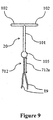
- the String(s) (112) emerge from the spherical bulge (105) leaving a hanging portion (19) of the string(s) (112) suspended freely.
- Figure-2 shows how the string(s) (112) get curled up and "disappear” from the vaginal cavity (18).
- the IUDs (10) accommodate their position in the uterus (17) during the first few months after insertion. This movement of the IUD (10) inside the uterus (17) is most probably explained by contractility, as illustrated by arrows (7) of the uterine muscle (myometrium).
- contractility as illustrated by arrows (7) of the uterine muscle (myometrium).
- the string(s) (112) is of a differential strength so that it meets following requirements:
- Figure-3 shows an IUD (10) placed in a uterus (17) with the string(s) (112) emerging from the spherical bulge (105), the string(s) (112) running through the endocervical canal (16) and the hanging portions (19) of the string(s) (112) freely suspended in the vaginal cavity (18) such that the string(s) (112) can be felt by woman.
- a length (8) of the central vertical stem (101) of the IUD (10) is generally of an order of 29-36mm and a distance (9) between a fundus (12) and an external cervical os (14) varies generally between 50mm and 100mm for different women depending on their age and other factors.
- a length of the endometrial cavity is greater than a length of the commonly used IUDs. This implies that the spherical bulge (105) and a part of string(s) (112) remain above the internal cervical os (15).
- an enhanced stiffness is achieved by unifying the strings.
- the unification which essentially means combination of multiple strings is by any of the several methods, namely, by fusing two or more strings or, by coiling/wrapping one or more string over another or, by interweaving two or more strings with each other or, by two or more strings glued together to form a thicker string or, by knots tied at the regular intervals or, by twisting two or more strings together to form the strings with thicker diameter.
- an enhanced stiffness is achieved by thickening the string either in the form of a continuously varying thickness, or a graded thickness, also termed as a stepped thickness.
- the enhanced stiffness is also achieved by providing an envelope around the string(s).
- the enhanced stiffness is also attained by use of a filament as a string, which is made of extra soft material (thus value of modulus of elasticity E is low) and has relatively much larger area of cross-section, so that the product of area of cross section A and modulus of elasticity E is increased.
- Figure-4 shows an embodiment with an IUD (20) having two strings (212) emerging from the spherical bulge (105) leaving the hanging portion (19) of the strings (212) freely suspended.
- a unification of the two or more strings (212) emerging from the spherical bulge (105) is a fusion of the two or more strings (212) together from below the spherical bulge (105) for a pre-determined length, hereinafter termed as a projected length (212a).
- the string(s) (212) are unified by fusing them together, from below the spherical bulge (105), for the projected length (212a) of the string(s) (212).
- the projected length (212a) remains inside the endocervical canal (16).
- the fusing together provides the enhanced stiffness and rigidity to the string(s) (212).
- the hanging portion (19) of the string(s) (212) is freely suspended in the vaginal cavity (18).
- the fusing could be by an ultrasonic welding or any other process by which a thermoplastic material, with or without additives, of which the strings (212) are made are brought to soft and thus fusible state. In the fusible state, the string(s) (212) are held together under a compressive force, which causes the discrete strings of the thermoplastic material to unify.
- the Fusion increases an area of cross-section of said strings (212), thus provides a required strength without altering a functionality of the string(s) (212).
- the hanging portion (19) of the string(s) (212) is either fused or unfused.
- Figure-5 shows another embodiment with the IUD (20) having two strings (312) emerging from the spherical bulge (105).
- a unification of the two or more strings (312) emerging from the spherical bulge (105) is a first string wrapped on a second string or a plurality of strings from below the spherical bulge for the projected length.
- To unify the strings (312) one of the two strings (312) is wrapped around on the other strings (312) from below the. spherical bulge (105) to form the projected length (312a) of the string (312), which remains inside the endocervical canal (16).
- the wrapping of the first string over the second string or others increases an area of cross-section of said strings (312), thus provides the enhanced stiffness without altering a functionality of the strings (312).
- the hanging portion (19) of the strings (312) is suspended in the vaginal cavity (18).
- the IUD (20) is having two or more strings (412) emerging from the spherical bulge (105).
- the unification of the two or more strings (412) emerging from the spherical bulge (105) is an interweave of the two or more strings (412) with one another to form a braid like structure below the spherical bulge for the projected length (412a).
- the strings (412) are interwoven with one another to form the braid like structure below the spherical bulge (105) to form the projected length (412a) of the strings (412) which remains inside the endocervical canal (16).
- the Interweaving of the strings (412) together increases an area of cross section of said strings (412), thus provides the enhanced stiffness without altering a functionality of the strings (412).
- the hanging portion (19) of the strings (412) is suspended freely in the vaginal cavity (18).
- the IUD (20) is having two strings (512) emerging from the spherical bulge (105).
- the unification of the two or more strings (512) emerging from the spherical bulge (105) is a glued portion of the two or more strings (512) together to form a string of a single thickness below the spherical bulge for the projected length (512a).
- the strings (512) are glued together below the spherical bulge (105) by use of an adhesive of medically approved grade to form the projected length (512a) of the strings (512).
- the Gluing of two or more strings (512) together increases an area of cross section of said strings (512), thus provides the enhanced stiffness without altering a functionality of the strings (512).
- the hanging portion (19) of two or more strings (512) is suspended freely in the vaginal cavity (18).
- Figure 8 shows another embodiment with IUD (20) having two or more strings (612) emerging from the spherical bulge (105).
- the unification of the two or more strings (612) is a division of the two or more strings (612) in nearly equally in two parts to form two set of said strings, said division of the two or more strings tied together by forming multiple knots at a regular intervals below the spherical bulge (105) for the projected length (612a).
- the number of strings are divided nearly equally in two parts so as to have only two set of said strings (612).
- the said strings (612) are tied together by forming multiple knots (11) at regular intervals below the spherical bulge (105) to form the projected length (612a) of two or more strings (612) in the endocervical canal (16).
- the Formation of multiple knots (11) is analogous to a rope formation or any other mechanical entanglement of two or more strings (612).
- Such multiple knots (11) at the regular interval increase an area of cross section of said the strings (612), thus provides the enhanced stiffness without altering a functionality of said strings (612).
- the hanging portion (19) of two or more strings (612) is freely suspended in the vaginal cavity (18).
- the string (812) emerging from the spherical bulge (105) of the IUD (20), as a preferred embodiment, is of a progressively varying or a graded thickness below the spherical bulge (105) to from the projected length of said string (812a).
- a highest thickness (22) in a vicinity of the spherical bulge (105) is of the an order of one and a half times to three times a thickness of a prior art string and a minimum thickness (23), which is at the other end of the projected length (812a) is same as that of a prior art string.
- Such graded thickness of said string increases an area of cross section in the projected length (812a), thus provides the enhanced stiffness without altering a functionality of said strings (812).
- the hanging portion (19) of the string (812) is of an uniform thickness (24) and which is same as the minimum thickness (23) and is freely suspended in the vaginal cavity (18).
- the Stepped thickness (25) is of an order of one and a half times to three times a thickness/diameter of a prior art string.
- Such stepped thickness (25) increases an area of cross section in the projected length (912a), thus provides an enhanced stiffness without altering a functionality of the string (912).
- the hanging portion (19) of the string (912) has same thickness/diameter (24) as known string and is freely suspended in the vaginal cavity (18).
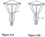
- FIG. 12 shows a preferred embodiment with an IUD (20) having one or more strings (1012) emerging from the spherical bulge (105) of IUD (20).
- the string(s) (1012) is guided by a tubular extension (12) of the spherical bulge (105) below the spherical bulge (105).
- the tubular extension (12) is straight or curvilinear.
- the tubular extension (12) is of such a length that the tubular extension (12) ends above the internal cervical os (15) as shown in Figure -12 A; or the tubular extension (12) is of such a length that the tubular extension (12) enters the endocervical canal (16) partially, as shown in Figure- 12B.
- the length of said string(s) (1012) inside the tubular extension (12) forms the projected length (1012a) of the string(s) (1012).
- the tubular extension (12) provides the required stiffness without altering a functionality of the string.
- the tubular extension (12), when curvilinear, also provides a springy action during the contraction of the uterus, preventing the curling of the string(s) (1012) inside the uterus (17).
- the hanging portion (19) of said string(s) (1012) is freely suspended in the vaginal cavity (18).
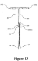
- Figure 13 shows another embodiment with an IUD (20) having one or more strings (1013) emerging from the spherical bulge (105) of IUD (20).
- the string(s) (1013) is fenced around, by a springy curvilinear extension (21) of the spherical bulge (105) below the spherical bulge (105).
- the springy curvilinear extension (21) is of such a length that the springy curvilinear extension (21) ends above the internal cervical os (15) as shown in Figure -13 A; or the springy curvilinear extension (21) is of such a length that the springy curvilinear extension (21) enters the endocervical canal (16) partially, as shown in Figure- 13 B.
- the length of said string(s) (1013) inside the springy curvilinear extension (21) forms the projected length (1013a) of the string(s) (1013).
- the springy curvilinear extension (21) provides the enhanced stiffness without altering the functionality of the string.
- the springy curvilinear extension (21) also provides the springy action during the contraction of the uterus preventing the curling of the string(s) (1013) inside the uterus (17).
- the hanging portion (19) of said string(s) (1013) is freely suspended in the vaginal cavity (18).
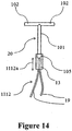
- the string(s) (1112) is guided by a stretchable hollow tube (13).
- the stretchable hollow tube (13) at least covers the spherical bulge (105) additionally.
- the hollow tube (13) may cover beyond the spherical bulge as shown in Figure-14A towards the proximal end (116), by being above the previously present copper winding or drug chamber.
- the stretchable hollow tube (13) may also cover beyond spherical bulge as shown in Figure- 14B towards the proximal end (116), by being below the previously present copper winding or drug chamber.
- the length of stretchable hollow tube (13) towards the string(s) (1112) is such that the hollow tube (13) ends above the internal cervical os (15) as shown in Figure-14C.
- the length of the hollow tube (13) towards the string(s) (1112) can also be such that the hollow tube (13) partially enters the endocervical canal (16) as shown in Figure- 14D.
- the ends of the hollow tube are sealed in order to prevent harboring of infection..
- the length of said two or more / a single string (1112) inside the hollow tube (13) forms the projected length (1112a) of the strings (1112).
- the hollow tube (13) restricts the upward movement of said string(s) (1112) from curling up inside the uterus (17).
- the hanging portion (19) of said string(s) (1112) is freely suspended in the vaginal cavity (18).
- the string is optionally provided with a plurality of identification by way of a mark, as show in Figure- 15, whether formed during manufacturing of the string or subsequently by an additional process, at measured intervals.
- identification aids the surgeon in cutting a right length of the string or the filament after leaving a recommended length of string of about 2 to 3 cm in the vaginal cavity.
- a hormone-releasing intrauterine system abbreviated as an IUS (30), as per this invention has a single string in the form of a filament (1212) of "jelly-like" extra soft material immediately below the distal end (114) of the stem (101).
- the diameter (26) of the filament is of the order of 1.5 to 10 times the diameter of a prior art string, with constrictions (27) at measured intervals.
- the constriction (27) facilitates trimming of the filament at desired measured length.
- the filament cannot curl up, and can cause no discomfort to the woman and or her partner.
- the spherical bulge illustrative shown in the Figure 16 is of a diameter more than a diameter of the central vertical stem, however, the spherical bulge can be of the diameter same as or less than the diameter of the central vertical stem.
Landscapes
- Health & Medical Sciences (AREA)
- Reproductive Health (AREA)
- Engineering & Computer Science (AREA)
- Biomedical Technology (AREA)
- Heart & Thoracic Surgery (AREA)
- Vascular Medicine (AREA)
- Life Sciences & Earth Sciences (AREA)
- Animal Behavior & Ethology (AREA)
- General Health & Medical Sciences (AREA)
- Public Health (AREA)
- Veterinary Medicine (AREA)
- Surgical Instruments (AREA)
- Orthopedics, Nursing, And Contraception (AREA)
Description
- This invention relates to the intrauterine device (IUD) and particularly to an IUD with one or more strings. More particularly, the invention relates to preventing curling up and retraction of the string(s) of the IUD in uterus.
- An intrauterine device (IUD) is a birth control device, which is placed in the uterus of a woman. IUDs have been known since several decades, and are popularly known as "Copper-T". IUDs are of different types viz. copper IUD, hormonal IUD, et cetera and are available in various shapes, for example T-shaped; and sized to fit inside uterus of women.
- IUDs currently in the market are generally provided with one or more strings extending from the bottom of the IUD. When IUD is placed in uterus, the string(s) extend through the cervix and remain positioned in the vaginal cavity, such that a woman can "feel" the presence of string(s) with her finger.
- IUD being a foreign matter in the body, there are possibilities that the IUD gets expelled from the uterus/body of the woman. Expulsions can happen anytime in the menstrual cycle (menstrual cycle is defined as duration from a start of one period to the start of the next period), more so during a heavy period. The causes of all expulsions are not exactly known, and expulsions are known to occur even if the period is not heavy. NuUiparous women, women with uterine abnormalities, fibroids are known to expel IUDs more commonly than others.
- Women are advised to "feel" the presence of the string(s) by touching the string(s) with their finger after each menstrual period or at regular intervals of weeks, so as to be assured of presence of the contraceptive device. String(s) are also helpful for pulling the IUD out of the uterus when the IUD is required to be removed. Patent
US3902483 describes an intrauterine device having two threads, a locator thread and a reserve thread. If women do not find the string, it makes them anxious that IUD has possibly got expelled and they are without protection from pregnancy. - Besides IUD getting expelled, there are many possible reasons for string not in place. One of the reasons that has relatively lately come to the knowledge is that strings are not in place although the IUD is in situ, that is, in the uterine cavity; because - the strings are curled up and retracted into the endocervical canal or uterine cavity. Patent
US4372302 andUS4561433 recognize this problem and describe instruments for retrieval of the retracted threads or strings of the IUD. These patents, however, do not address the cause and solution of the problem of curling/retracting. - Patent Publication Number
EP0179518A1 describes an IUD extractor thread where an IUD is provided with an extractor thread and such thread is coated with metallic silver which helps in preventing the bacteriological infections which occur due to the normal threads of IUD. Although this invention deals with the IUD threads, but does not address curling. - Patent Publication Number
US2011/0247630 describes an intrauterine device with string divided into upper, intermediate and lower portion. The upper portion is configured to attach the stem of IUD. Intermediate portion runs through endocervical canal and lower portion follows the contour of cervix. The disclosure is silent about string curling. The lower portion comprising a curved portion is configured to follow a contour of the external orifice of the cervix; and therefore, this method may prevent up curling of string, however, the procedure is painful, complex and intervening with active life of the women and her partner; and therefore is impractical. - One of the common ways to attach the string to the IUD frame is by having a through hole at the lower end of the IUD frame and tying the string by way of a knot. Patent application Number
US2013/0298361A1 describes the knotting method. This disclosure is more towards achieving productivity rather than addressing said problem. - As can be easily appreciated, there is no prior invention which addresses the problem related to curling or retraction of strings.
- Our invention addresses the cause of curling and or retracting of knotted strings and solves this problem.
- The objective of the invention is to provide an intra-uterine device wherein the string does not retract into the uterus through the endocervical canal of the female.
- Another objective of the invention is to provide an intra-uterine device which is not unduly different in construction than current devices.
- Yet another objective is to invent an intrauterine device with ease of manufacturing and the end product being economical.
- Yet another objective of the invention is to provide an intrauterine device which is as hygienic, safe and proven for inserting in the uterus of the female as current devices.
- Our invention deals with an intrauterine device with a restricted movement of a string. T-shaped IUD is considered for disclosure of our invention, however, the shape of the IUD is not a limitation and this invention pertains to IUDs of all shapes and type, whether copper or hormonal or medicinal.
- An intrauterine device described here comprises of a central vertical stem having a plurality of arms attached at a proximal end and a spherical bulge. IUDs are provided with one or more strings which are attached to the stem either by knotting or by molding along with a frame of the IUD. String(s) emerge from the spherical bulge leaving the hanging portion of the string(s) freely suspended. The strings are soft and therefore can easily develop a tendency to curl / bend. These string(s) serve the purpose of ensuring presence of IUD, and removal of the IUD.
- The present invention recognizes that the string(s) is required to be of differential strength so that it meets following requirements:
- Requirement ONE: The string(s) ought to be soft, and hanging portion of the string(s) "feelable" in the vaginal cavity, should not cause discomfort to the woman, nor bruise the organ of the partner during an intercourse.
- Requirement TWO: The string(s) reaching the internal cervical os ought to be relatively stiffer and not have the tendency to get curled up progressively.
- Consequent to the contracting and relaxing muscular activities of the uterus, the string(s) gets gradually pulled or slid from the endocervical canal, thereby curling up in the uterus. Commonly available IUDs comprise of a single or two strings, emerging from the spherical bulge. An intrauterine device or an IUD as per this invention prevents a curling and retraction of the string(s) in the uterus by enhanced stiffness for the limited and specific length, termed as predetermined length.
- According to this invention, an enhanced stiffness is achieved by unifying the strings. The unification, which essentially means combination of multiple strings is by any of the several methods, namely, by fusing two or more strings or, by coiling/wrapping one or more string over another or, by interweaving two or more strings with each other or, by two or more strings glued together to form a thicker string or, by knots tied at the regular intervals or, by twisting two or more strings together to form the strings with thicker diameter. In the IUD with a single string, a desired stiffness is achieved by thickening the string either in the form of a continuously varying thickness, or graded thickness, also termed as stepped thickness. The desired stiffness is also achieved by providing an envelope around the string(s). The desired stiffness is also attained by use of a filament as a string, which is made of extra soft material (thus value of modulus of elasticity E is low) and has relatively much larger area of cross-section, so that the product of area of cross section A and modulus of elasticity E is increased. String is optionally provided with a plurality of identification by way of a mark, whether formed during manufacturing of the string or subsequently by an additional process, at measured intervals. Such identification aids the surgeon in cutting a right length of the string or the filament after leaving a recommended length of string of about 2 to 3 cm in the vaginal cavity.
-
- Figure- 1 A and Figure- IB show prior art IUDs with one or more than one string.
- Figure-2 illustrates how the progressive curling up of the strings occurs.
- Figure-3 shows position of different parts of IUD and string in the uterus, endocervical canal and vaginal cavity.
- Figure-4 shows a preferred embodiment of unification of strings.
- Figure-5 shows another embodiment of unification of strings.
- Figure-6 shows yet another embodiment of unification of strings.
- Figure-7, 8 and 9 show yet another embodiment of unification of strings.
- Figure- 10 and Figure- 1 1 show embodiments of this invention with single string.
- Figure- 12 shows a preferred embodiment whereby an envelope is provided around the string, while Figure- 12A and 12B show the extent of envelope.
- Figure- 13 shows another embodiment whereby an envelope is provided around the string, while Figure-13A and 13B show the extent of envelope.
- Figure-14 shows another embodiment whereby an envelope is provided around the string, while Figure-14, 14B, 14C and 14D show the extent of envelope oh either ends.
-
Figure 15 shows identification marks provided on the string(s). - Reference
Figure 16 shows a single string in the form of a filament with identification marks. - Preferred embodiment of the intra-uterine device (IUD) with a restricted movement of a string according to present invention will now be described in detail, with reference to the accompanying drawings. The terms and expressions which have been used here are merely for description and not for limitation. A "T-shaped" IUD is considered for illustration of our invention, however, the shape of the IUD is not a limitation and this invention pertains to IUDs of all shapes and type, whether copper/silver-copper or hormonal or medicinal.
- The known IUDs are provided with one or more strings. The string(s) is attached to the stem either by knotting or by molding along with a frame of the IUD. The strings are soft and therefore can easily develop a tendency to curl / bend. Figure- 1 A showing a prior art intrauterine device (10) or IUD (10) comprises a central vertical stem (101) having a pair of arms (102) attached on a proximal end (116) of the central vertical stem (101), and a spherical bulge (105) at a distal end (114) of the central vertical stem (101). The String(s) (112) emerge from the spherical bulge (105) leaving a hanging portion (19) of the string(s) (112) suspended freely. These string(s) (112) serve the purpose of ensuring presence of the IUD (10), and removal of the IUD (10). As shown in Figure-3, When the IUD (10) is placed into the uterus (17); these string(s) (112) extend through the endocervical canal (16) and remain positioned in the vaginal cavity (18). Figure- IB shows another prior art intrauterine device (10) having a single string (112) suspended freely.
- Figure-2, read with earlier figures, shows how the string(s) (112) get curled up and "disappear" from the vaginal cavity (18). It is known that the IUDs (10) accommodate their position in the uterus (17) during the first few months after insertion. This movement of the IUD (10) inside the uterus (17) is most probably explained by contractility, as illustrated by arrows (7) of the uterine muscle (myometrium). During downward movement of the IUD (10) in the uterus (17), there is relative upward movement of the string(s) (112) against the central vertical stem (101) of the IUD (10) due to a differential stiffness of the central vertical stem (101) and a differential stiffness of the string(s) (112). It is easy to comprehend that the phenomenon of curling of string(s) (112) begins from a vicinity of a joint of the string(s) (112) with the spherical bulge (105) of the IUD (10). View-I, View-II, View-III and View-IV in Figure-2 shows progressive curling up and retraction of the string(s) (1 12) into the endocervical canal (16) and gradually into the uterus (17).
- As per present invention, the string(s) (112) is of a differential strength so that it meets following requirements:
- Requirement ONE: The string(s) (112) ought to be soft, and the hanging portion (19) of the string(s) (112) "feelable" in the vaginal cavity (18), should not cause discomfort to the woman, nor bruise the organ of the partner during an intercourse.
- Requirement TWO: The string(s) (112) reaching the internal cervical os (15) ought to be relatively stiffer and not have the tendency to get curled up progressively.
- Figure-3 shows an IUD (10) placed in a uterus (17) with the string(s) (112) emerging from the spherical bulge (105), the string(s) (112) running through the endocervical canal (16) and the hanging portions (19) of the string(s) (112) freely suspended in the vaginal cavity (18) such that the string(s) (112) can be felt by woman. A length (8) of the central vertical stem (101) of the IUD (10) is generally of an order of 29-36mm and a distance (9) between a fundus (12) and an external cervical os (14) varies generally between 50mm and 100mm for different women depending on their age and other factors. In most women, a length of the endometrial cavity (distance from fundus to internal cervical os (15) is greater than a length of the commonly used IUDs. This implies that the spherical bulge (105) and a part of string(s) (112) remain above the internal cervical os (15).
- It is known that consequent to the contracting and relaxing muscular activities of the uterus (17), the string(s) (112) gets gradually pulled or slid from the endocervical canal (16), thereby curling up in the uterus (17). Commonly available IUDs (10) comprise of a single or two strings (112), emerging from the spherical bulge (105) as shown in Figure- IB and Figure- 1A respectively. An intra-uterine device or an IUD as per this invention prevents a curling and retraction of the string(s) (112) in the uterus (17) by an enhanced stiffness for a limited and specific length, termed as a predetermined length. The Stiffness can be arithmetically understood by the equation:

- k = stiffness
- A = area of cross-section
- E = modulus of elasticity of the material
- L = length
- Hence, it is clear that stiffness is directly proportional to the cross-section, or
- k a A (where a is the sign of proportionality)
- According to this invention, described with Figures -4 onwards, in an IUD (20) with two or more strings, an enhanced stiffness is achieved by unifying the strings. The unification, which essentially means combination of multiple strings is by any of the several methods, namely, by fusing two or more strings or, by coiling/wrapping one or more string over another or, by interweaving two or more strings with each other or, by two or more strings glued together to form a thicker string or, by knots tied at the regular intervals or, by twisting two or more strings together to form the strings with thicker diameter. In the IUD (20) with a single string, an enhanced stiffness is achieved by thickening the string either in the form of a continuously varying thickness, or a graded thickness, also termed as a stepped thickness. The enhanced stiffness is also achieved by providing an envelope around the string(s). The enhanced stiffness is also attained by use of a filament as a string, which is made of extra soft material (thus value of modulus of elasticity E is low) and has relatively much larger area of cross-section, so that the product of area of cross section A and modulus of elasticity E is increased.
- Figure-4, shows an embodiment with an IUD (20) having two strings (212) emerging from the spherical bulge (105) leaving the hanging portion (19) of the strings (212) freely suspended. A unification of the two or more strings (212) emerging from the spherical bulge (105) is a fusion of the two or more strings (212) together from below the spherical bulge (105) for a pre-determined length, hereinafter termed as a projected length (212a). The string(s) (212) are unified by fusing them together, from below the spherical bulge (105), for the projected length (212a) of the string(s) (212). The projected length (212a) remains inside the endocervical canal (16). The fusing together provides the enhanced stiffness and rigidity to the string(s) (212). The hanging portion (19) of the string(s) (212) is freely suspended in the vaginal cavity (18). The fusing could be by an ultrasonic welding or any other process by which a thermoplastic material, with or without additives, of which the strings (212) are made are brought to soft and thus fusible state. In the fusible state, the string(s) (212) are held together under a compressive force, which causes the discrete strings of the thermoplastic material to unify. The Fusion increases an area of cross-section of said strings (212), thus provides a required strength without altering a functionality of the string(s) (212). The hanging portion (19) of the string(s) (212) is either fused or unfused.
- Figure-5 shows another embodiment with the IUD (20) having two strings (312) emerging from the spherical bulge (105). A unification of the two or more strings (312) emerging from the spherical bulge (105) is a first string wrapped on a second string or a plurality of strings from below the spherical bulge for the projected length. To unify the strings (312), one of the two strings (312) is wrapped around on the other strings (312) from below the. spherical bulge (105) to form the projected length (312a) of the string (312), which remains inside the endocervical canal (16). The wrapping of the first string over the second string or others increases an area of cross-section of said strings (312), thus provides the enhanced stiffness without altering a functionality of the strings (312).The hanging portion (19) of the strings (312) is suspended in the vaginal cavity (18).
- Another embodiment as shown in Figure-6, the IUD (20) is having two or more strings (412) emerging from the spherical bulge (105). The unification of the two or more strings (412) emerging from the spherical bulge (105) is an interweave of the two or more strings (412) with one another to form a braid like structure below the spherical bulge for the projected length (412a). To unify the strings (412), the strings (412) are interwoven with one another to form the braid like structure below the spherical bulge (105) to form the projected length (412a) of the strings (412) which remains inside the endocervical canal (16). The Interweaving of the strings (412) together increases an area of cross section of said strings (412), thus provides the enhanced stiffness without altering a functionality of the strings (412). The hanging portion (19) of the strings (412) is suspended freely in the vaginal cavity (18).
- As another embodiment shown in Figure-7, the IUD (20) is having two strings (512) emerging from the spherical bulge (105). The unification of the two or more strings (512) emerging from the spherical bulge (105) is a glued portion of the two or more strings (512) together to form a string of a single thickness below the spherical bulge for the projected length (512a). To unify, the strings (512) are glued together below the spherical bulge (105) by use of an adhesive of medically approved grade to form the projected length (512a) of the strings (512). The Gluing of two or more strings (512) together increases an area of cross section of said strings (512), thus provides the enhanced stiffness without altering a functionality of the strings (512). The hanging portion (19) of two or more strings (512) is suspended freely in the vaginal cavity (18).
-
Figure 8 shows another embodiment with IUD (20) having two or more strings (612) emerging from the spherical bulge (105). The unification of the two or more strings (612) is a division of the two or more strings (612) in nearly equally in two parts to form two set of said strings, said division of the two or more strings tied together by forming multiple knots at a regular intervals below the spherical bulge (105) for the projected length (612a). To unify, the number of strings are divided nearly equally in two parts so as to have only two set of said strings (612). The said strings (612) are tied together by forming multiple knots (11) at regular intervals below the spherical bulge (105) to form the projected length (612a) of two or more strings (612) in the endocervical canal (16). The Formation of multiple knots (11) is analogous to a rope formation or any other mechanical entanglement of two or more strings (612). Such multiple knots (11) at the regular interval increase an area of cross section of said the strings (612), thus provides the enhanced stiffness without altering a functionality of said strings (612). The hanging portion (19) of two or more strings (612) is freely suspended in the vaginal cavity (18). - In another embodiment as shown in Figure-9 with an IUD (20) having two or more strings (712) emerging from the spherical bulge (105) of IUD (20). The unification of the two or more strings (712) emerging from the spherical bulge (105) is a twist of the two or more strings (712) with one another below the spherical bulge (105) for the projected length (712a).To unify, the two or more strings (712) are twisted with each other below the spherical bulge (105) to form the projected length (712a) in the endocervial canal (16). Such twisting of two or more strings increases an area of cross section of said strings (712), thus provides the enhanced stiffness without altering a functionality of said strings (712). The hanging portion (19) of two or more strings (712) is freely suspended in the vaginal cavity (18).
- According to this invention for IUD (20) with a single string (812), as shown in Figure- 10, the string (812) emerging from the spherical bulge (105) of the IUD (20), as a preferred embodiment, is of a progressively varying or a graded thickness below the spherical bulge (105) to from the projected length of said string (812a). A highest thickness (22) in a vicinity of the spherical bulge (105) is of the an order of one and a half times to three times a thickness of a prior art string and a minimum thickness (23), which is at the other end of the projected length (812a) is same as that of a prior art string. Such graded thickness of said string increases an area of cross section in the projected length (812a), thus provides the enhanced stiffness without altering a functionality of said strings (812). The hanging portion (19) of the string (812) is of an uniform thickness (24) and which is same as the minimum thickness (23) and is freely suspended in the vaginal cavity (18).
- As another embodiment as shown in the Figure- 11, an IUD (20) having the single string (912) emerging from the spherical bulge (105) of IUD (20), has the string (912) of a stepped thickness (25) such that the thicker string forms the projected length (912a) of said string (912). The Stepped thickness (25) is of an order of one and a half times to three times a thickness/diameter of a prior art string. Such stepped thickness (25) increases an area of cross section in the projected length (912a), thus provides an enhanced stiffness without altering a functionality of the string (912). The hanging portion (19) of the string (912) has same thickness/diameter (24) as known string and is freely suspended in the vaginal cavity (18).
- According to this invention, an enhanced stiffness is also achieved by providing an envelope around the string(s).
Figure 12 shows a preferred embodiment with an IUD (20) having one or more strings (1012) emerging from the spherical bulge (105) of IUD (20). The string(s) (1012) is guided by a tubular extension (12) of the spherical bulge (105) below the spherical bulge (105). The tubular extension (12) is straight or curvilinear. The tubular extension (12) is of such a length that the tubular extension (12) ends above the internal cervical os (15) as shown in Figure -12 A; or the tubular extension (12) is of such a length that the tubular extension (12) enters the endocervical canal (16) partially, as shown in Figure- 12B. The length of said string(s) (1012) inside the tubular extension (12) forms the projected length (1012a) of the string(s) (1012). The tubular extension (12) provides the required stiffness without altering a functionality of the string. The tubular extension (12), when curvilinear, also provides a springy action during the contraction of the uterus, preventing the curling of the string(s) (1012) inside the uterus (17). The hanging portion (19) of said string(s) (1012) is freely suspended in the vaginal cavity (18). -
Figure 13 shows another embodiment with an IUD (20) having one or more strings (1013) emerging from the spherical bulge (105) of IUD (20). The string(s) (1013) is fenced around, by a springy curvilinear extension (21) of the spherical bulge (105) below the spherical bulge (105). The springy curvilinear extension (21) is of such a length that the springy curvilinear extension (21) ends above the internal cervical os (15) as shown in Figure -13 A; or the springy curvilinear extension (21) is of such a length that the springy curvilinear extension (21) enters the endocervical canal (16) partially, as shown in Figure- 13 B. The length of said string(s) (1013) inside the springy curvilinear extension (21) forms the projected length (1013a) of the string(s) (1013). The springy curvilinear extension (21) provides the enhanced stiffness without altering the functionality of the string. The springy curvilinear extension (21) also provides the springy action during the contraction of the uterus preventing the curling of the string(s) (1013) inside the uterus (17). The hanging portion (19) of said string(s) (1013) is freely suspended in the vaginal cavity (18). - In another embodiment as shown in the
figure 14 , for an IUD (20) having one or more string (1112) emerging from the spherical bulge (105) of the IUD (20), the string(s) (1112) is guided by a stretchable hollow tube (13). The stretchable hollow tube (13) at least covers the spherical bulge (105) additionally. The hollow tube (13) may cover beyond the spherical bulge as shown in Figure-14A towards the proximal end (116), by being above the previously present copper winding or drug chamber. The stretchable hollow tube (13) may also cover beyond spherical bulge as shown in Figure- 14B towards the proximal end (116), by being below the previously present copper winding or drug chamber. The length of stretchable hollow tube (13) towards the string(s) (1112) is such that the hollow tube (13) ends above the internal cervical os (15) as shown in Figure-14C. The length of the hollow tube (13) towards the string(s) (1112) can also be such that the hollow tube (13) partially enters the endocervical canal (16) as shown in Figure- 14D. In all variations, the ends of the hollow tube are sealed in order to prevent harboring of infection.. The length of said two or more / a single string (1112) inside the hollow tube (13) forms the projected length (1112a) of the strings (1112).The hollow tube (13) restricts the upward movement of said string(s) (1112) from curling up inside the uterus (17). The hanging portion (19) of said string(s) (1112) is freely suspended in the vaginal cavity (18). - In all above embodiments, the string is optionally provided with a plurality of identification by way of a mark, as show in Figure- 15, whether formed during manufacturing of the string or subsequently by an additional process, at measured intervals. Such identification aids the surgeon in cutting a right length of the string or the filament after leaving a recommended length of string of about 2 to 3 cm in the vaginal cavity.
- In the disclosure as shown in
figure 16 a hormone-releasing intrauterine system, abbreviated as an IUS (30), as per this invention has a single string in the form of a filament (1212) of "jelly-like" extra soft material immediately below the distal end (114) of the stem (101). The diameter (26) of the filament is of the order of 1.5 to 10 times the diameter of a prior art string, with constrictions (27) at measured intervals. The constriction (27) facilitates trimming of the filament at desired measured length. The filament cannot curl up, and can cause no discomfort to the woman and or her partner. - The spherical bulge illustrative shown in the
Figure 16 is of a diameter more than a diameter of the central vertical stem, however, the spherical bulge can be of the diameter same as or less than the diameter of the central vertical stem.
Claims (14)
- An intrauterine device (20) with a restricted upward movement of two or more strings (212, 312, 412, 512, 612, 712), having a central vertical stem (101) with a plurality of arms (102) attached on a proximal end (116) of the central vertical stem (101) and said two or more strings (212, 312, 412, 512, 612, 712) emerging from a spherical bulge (105), having a hanging portion (19) of said two or more strings (212, 312, 412, 512, 612, 712) suspended freely in the vaginal cavity (18), characterized by a unification of the two or more strings (212, 312, 412, 512, 612, 712) from below the spherical bulge (105) for a projected length (212a, 312a, 412a, 512a, 612a, 712a) that remains inside an endocervical canal (16), to achieve an enhanced stiffness so as to restrict an upward movement of the hanging portion (19) of the two or more strings (212, 312, 412, 512, 612, 712) in the uterus (17).
- The intrauterine device (20) with the restricted movement of the two or more strings (212, 312, 412, 512, 612, 712) as claimed in claim 1, wherein said unification of the two or more strings (212, 312, 412, 512, 612, 712) emerging from the spherical bulge (105) is a fusion of the two or more strings (212, 312, 412, 512, 612, 712) together from below the spherical (105) bulge for the projected length of the string (212a, 312a, 412a, 512a, 612a, 712a).
- The intrauterine device (20) with the restricted movement of the two or more strings (412) as claimed in claim 1, wherein said unification of the two or more strings (412) emerging from the spherical bulge is an interweave of the two or more strings (412) with one another below the spherical bulge (105) for the projected length of the string (412a).
- The intrauterine device (20) with the restricted movement of the two or more strings (512) as claimed in claim 1, wherein said unification of the two or more strings (512) emerging from the spherical bulge (105) is a glued portion of the two or more strings (512) together to form a string of a single thickness below the spherical bulge for the projected length of the string (512a).
- The intrauterine device (20) with a restricted upward movement of the two or more strings (212, 312, 412, 512, 612, 712) as claimed in claim 1, wherein said plurality of strings (212, 312, 412, 512, 612, 712) is provided with a plurality of identification by way of a mark at measured intervals.
- An intrauterine device (200) with a restricted upward movement of a string (812, 912), having a central vertical stem (101) with a plurality of arms (102) attached on a proximal end (106) of the central vertical stem (101) and said string (812, 912) emerging from a spherical bulge (105), having a hanging portion (19) of said string (812, 912) suspended freely in the vaginal cavity (18); characterized by an increased cross section of the hanging portion (19) of said string (812) from below the spherical bulge (105) for a projected length (812a, 912a) that remains inside an endocervical canal (16), to achieve an enhanced stiffness so as to restrict an upward movement of the hanging portion (19) of the string (812, 912) in the uterus (17).
- The intrauterine device (20) with the restricted movement of the string (812, 912) as claimed in claim 6, wherein said increased cross section of the string (812, 912) is a progressively varying or a graded thickness (22, 23) of the string (812, 912) emerging from the spherical bulge (105) for the projected length (812a, 912a) of the string (812, 912).
- The intrauterine device (20) with the restricted movement of the string (912) as claimed in claim 6, wherein said increased cross section of the string (912) is a stepped thickness (25) of the string (912) emerging from the spherical bulge (105) for the projected length string (912a).
- An intrauterine device (20) with a restricted upward movement of a plurality of strings (1012, 1013, 1112), having a central vertical stem (101) with a plurality of arms (102) attached on a proximal end (106) of the central vertical stem (101) and the plurality of strings (1012, 1013, 1112) emerging from a spherical bulge (105), having a hanging portion (19) of said plurality of strings (1012, 1013, 1112) suspended freely in the vaginal cavity (18), characterized by an envelope around the plurality of strings (1012, 1013, 1112) emerging from below the spherical bulge (105) to achieve an enhanced stiffness for a projected length (1012a, 1013a, 1112a) that remains inside the endocervical canal (16) so as to restrict the upward movement of the plurality of the strings (1012, 1013, 1112) in the uterus (17).
- The intrauterine device (20) with the restricted movement of the strings (1012, 1013, 1112) as claimed in claim 9, wherein said envelope around the plurality of strings (1012, 1013, 1112) is a tubular extension (12) of the spherical bulge (105).
- The intrauterine device (20) with the restricted movement of the strings (1013) as claimed in claim 9, wherein said envelope around the one or more strings (1013) is a springy curvilinear extension of the spherical bulge (105) and the string(s) (1013) is fenced around by the springy curvilinear extension (21).
- The intrauterine device (20) with the restricted movement of the strings (1112) as claimed in claim 9, wherein said envelope around the one or more strings (1112) is a stretchable hollow tube (13) of the spherical bulge (105) and the string(s) (1112) is guided by the stretchable hollow tube (13).
- The intrauterine device (20) with then restricted movement of the strings (1112) as claimed in claim 12, wherein said stretchable hollow tube (13) at least covers the spherical bulge (105).
- The intrauterine device (20) with then restricted movement of the strings (1112) as claimed in claim 12, wherein said stretchable hollow tube (13) covers beyond the spherical bulge (105) towards the proximal end (106) having a copper winding or a drug chamber.
Applications Claiming Priority (2)
| Application Number | Priority Date | Filing Date | Title |
|---|---|---|---|
| IN2100MU2015 | 2015-05-30 | ||
| PCT/IN2015/000286 WO2016193987A1 (en) | 2015-05-30 | 2015-07-16 | Intrauterine device with a restricted upward movement of a string |
Publications (3)
| Publication Number | Publication Date |
|---|---|
| EP3302378A1 EP3302378A1 (en) | 2018-04-11 |
| EP3302378A4 EP3302378A4 (en) | 2019-02-13 |
| EP3302378B1 true EP3302378B1 (en) | 2021-10-20 |
Family
ID=57440745
Family Applications (1)
| Application Number | Title | Priority Date | Filing Date |
|---|---|---|---|
| EP15894050.2A Active EP3302378B1 (en) | 2015-05-30 | 2015-07-16 | Intrauterine device with a restricted upward movement of a string |
Country Status (4)
| Country | Link |
|---|---|
| US (1) | US11026832B2 (en) |
| EP (1) | EP3302378B1 (en) |
| BR (1) | BR112017024435A2 (en) |
| WO (1) | WO2016193987A1 (en) |
Families Citing this family (2)
| Publication number | Priority date | Publication date | Assignee | Title |
|---|---|---|---|---|
| EP4176886A2 (en) * | 2020-07-06 | 2023-05-10 | Sanders Esparza, María Fernanda | Method for reducing the incidence and prevalence of human papillomavirus (hpv) and for providing protection against sexually transmitted infections |
| CN116963699A (en) * | 2021-01-01 | 2023-10-27 | 罗西尼·沙恭达罗·塞内维拉特纳 | Marked monofilament retrieval lines for use with intrauterine systems or devices or other intraluminal devices and methods of making same |
Family Cites Families (17)
| Publication number | Priority date | Publication date | Assignee | Title |
|---|---|---|---|---|
| US2122579A (en) * | 1934-06-13 | 1938-07-05 | Louis W Meckstroth | Intra-uterine device |
| US3507274A (en) * | 1968-03-18 | 1970-04-21 | Samuel Soichet | Intra-uterine device |
| US3993057A (en) * | 1972-12-27 | 1976-11-23 | Alza Corporation | Intrauterine device that bioerodes in response to the environment of the uterus and method of using |
| US3902483A (en) * | 1974-08-21 | 1975-09-02 | Alza Corp | Intrauterine device with locator means for indicating uterine position of device |
| SE417274B (en) | 1980-04-09 | 1981-03-09 | Mats Akerlund | PROBLEM FOR RETIRING WITHDRAWALS |
| US4578076A (en) * | 1984-03-20 | 1986-03-25 | The Population Council, Inc. | Medicated intracervical and intrauterine devices |
| US4561433A (en) | 1984-08-27 | 1985-12-31 | Family Health International | Intrauterine device remover |
| EP0179518A1 (en) | 1984-10-16 | 1986-04-30 | Akzo N.V. | IUD extractor thread |
| US5234437A (en) * | 1991-12-12 | 1993-08-10 | Target Therapeutics, Inc. | Detachable pusher-vasoocclusion coil assembly with threaded coupling |
| NL1030795C2 (en) * | 2005-12-27 | 2007-06-28 | Willem Arthur Adriaan Van Os | Intra-uterine device and sleeve for introducing it into the uterus. |
| US20080216842A1 (en) * | 2008-02-19 | 2008-09-11 | Guillermo Sanders Acedo | Contraceptive device designed for mexican women according to the dimensions of their uterine cavity acoording to their parity |
| FI20085277A0 (en) * | 2008-04-02 | 2008-04-02 | Bayer Schering Pharma Oy | Intrauterine system |
| US8490625B2 (en) | 2010-04-13 | 2013-07-23 | Laura Ann Schneider | Intrauterine device string |
| EP2673230B1 (en) | 2011-02-08 | 2015-01-14 | Odyssea Pharma S.A. | Apparatus for knotting drawstrings of medical devices or medical devices containing drugs |
| US10028858B2 (en) * | 2011-07-11 | 2018-07-24 | Medicines360 | Intrauterine systems, IUD insertion devices, and related methods and kits therefor |
| WO2014023797A1 (en) * | 2012-08-09 | 2014-02-13 | Odyssea Pharma S.P.R.L. | Intrauterine device |
| WO2016059640A1 (en) * | 2014-10-17 | 2016-04-21 | Pregna International Limited | An intrauterine device with a restricted movement of a string knot |
-
2015
- 2015-07-16 EP EP15894050.2A patent/EP3302378B1/en active Active
- 2015-07-16 BR BR112017024435A patent/BR112017024435A2/en not_active Application Discontinuation
- 2015-07-16 WO PCT/IN2015/000286 patent/WO2016193987A1/en active Application Filing
- 2015-07-16 US US15/576,362 patent/US11026832B2/en active Active
Non-Patent Citations (1)
| Title |
|---|
| None * |
Also Published As
| Publication number | Publication date |
|---|---|
| EP3302378A4 (en) | 2019-02-13 |
| WO2016193987A1 (en) | 2016-12-08 |
| US20180147085A1 (en) | 2018-05-31 |
| EP3302378A1 (en) | 2018-04-11 |
| BR112017024435A2 (en) | 2018-07-24 |
| US11026832B2 (en) | 2021-06-08 |
Similar Documents
| Publication | Publication Date | Title |
|---|---|---|
| US3973560A (en) | Intrauterine device of C or omega form | |
| US9308119B2 (en) | Intrauterine device and inserter for the same | |
| CN106999292B (en) | Device placeable in the uterine cavity | |
| US4111196A (en) | Intrauterine contraceptive device of c or omega form with tubular inserter and method of placement | |
| WO2008027292A3 (en) | Cervical dilator and methods of use | |
| WO2015041353A1 (en) | Ring pessary for treatment of uterine prolapse or hysteroptosis | |
| EP3302378B1 (en) | Intrauterine device with a restricted upward movement of a string | |
| US3675648A (en) | Intrauterine contraceptive device | |
| EP1539062B1 (en) | Soft cling female condom | |
| US4038978A (en) | Intrauterine device | |
| US10588777B2 (en) | Intrauterine device with a restricted movement of a string knot | |
| DK164728B (en) | COLLECTION CONSISTS OF AN INTRAUTERIN PREGNANCY DEVICE AND AN IMPOSITION DEVICE | |
| US7926488B2 (en) | Frame of an intrauterine system | |
| US8490625B2 (en) | Intrauterine device string | |
| US3675647A (en) | Intrauterine contraceptive device | |
| CN217697037U (en) | Treatment ring and ring fitting device | |
| US20140345624A1 (en) | Intrauterine Device Remover | |
| JP2021118955A (en) | Device positionable in uterine cavity | |
| WO2019013718A1 (en) | A malleable penile implant | |
| JP2003520071A (en) | Contraceptive device for women | |
| JPS6236697B2 (en) |
Legal Events
| Date | Code | Title | Description |
|---|---|---|---|
| STAA | Information on the status of an ep patent application or granted ep patent |
Free format text: STATUS: THE INTERNATIONAL PUBLICATION HAS BEEN MADE |
|
| PUAI | Public reference made under article 153(3) epc to a published international application that has entered the european phase |
Free format text: ORIGINAL CODE: 0009012 |
|
| STAA | Information on the status of an ep patent application or granted ep patent |
Free format text: STATUS: REQUEST FOR EXAMINATION WAS MADE |
|
| 17P | Request for examination filed |
Effective date: 20171116 |
|
| AK | Designated contracting states |
Kind code of ref document: A1 Designated state(s): AL AT BE BG CH CY CZ DE DK EE ES FI FR GB GR HR HU IE IS IT LI LT LU LV MC MK MT NL NO PL PT RO RS SE SI SK SM TR |
|
| AX | Request for extension of the european patent |
Extension state: BA ME |
|
| DAV | Request for validation of the european patent (deleted) | ||
| DAX | Request for extension of the european patent (deleted) | ||
| A4 | Supplementary search report drawn up and despatched |
Effective date: 20190110 |
|
| RIC1 | Information provided on ipc code assigned before grant |
Ipc: A61F 6/06 20060101AFI20190104BHEP Ipc: A61F 6/14 20060101ALI20190104BHEP Ipc: A61F 6/18 20060101ALI20190104BHEP |
|
| STAA | Information on the status of an ep patent application or granted ep patent |
Free format text: STATUS: EXAMINATION IS IN PROGRESS |
|
| 17Q | First examination report despatched |
Effective date: 20191203 |
|
| STAA | Information on the status of an ep patent application or granted ep patent |
Free format text: STATUS: EXAMINATION IS IN PROGRESS |
|
| GRAP | Despatch of communication of intention to grant a patent |
Free format text: ORIGINAL CODE: EPIDOSNIGR1 |
|
| STAA | Information on the status of an ep patent application or granted ep patent |
Free format text: STATUS: GRANT OF PATENT IS INTENDED |
|
| INTG | Intention to grant announced |
Effective date: 20210812 |
|
| GRAS | Grant fee paid |
Free format text: ORIGINAL CODE: EPIDOSNIGR3 |
|
| GRAA | (expected) grant |
Free format text: ORIGINAL CODE: 0009210 |
|
| STAA | Information on the status of an ep patent application or granted ep patent |
Free format text: STATUS: THE PATENT HAS BEEN GRANTED |
|
| AK | Designated contracting states |
Kind code of ref document: B1 Designated state(s): AL AT BE BG CH CY CZ DE DK EE ES FI FR GB GR HR HU IE IS IT LI LT LU LV MC MK MT NL NO PL PT RO RS SE SI SK SM TR |
|
| REG | Reference to a national code |
Ref country code: GB Ref legal event code: FG4D |
|
| REG | Reference to a national code |
Ref country code: CH Ref legal event code: EP |
|
| REG | Reference to a national code |
Ref country code: DE Ref legal event code: R096 Ref document number: 602015074372 Country of ref document: DE |
|
| REG | Reference to a national code |
Ref country code: IE Ref legal event code: FG4D |
|
| REG | Reference to a national code |
Ref country code: AT Ref legal event code: REF Ref document number: 1439301 Country of ref document: AT Kind code of ref document: T Effective date: 20211115 |
|
| REG | Reference to a national code |
Ref country code: FI Ref legal event code: FGE |
|
| REG | Reference to a national code |
Ref country code: LT Ref legal event code: MG9D |
|
| REG | Reference to a national code |
Ref country code: NL Ref legal event code: MP Effective date: 20211020 |
|
| REG | Reference to a national code |
Ref country code: AT Ref legal event code: MK05 Ref document number: 1439301 Country of ref document: AT Kind code of ref document: T Effective date: 20211020 |
|
| PG25 | Lapsed in a contracting state [announced via postgrant information from national office to epo] |
Ref country code: RS Free format text: LAPSE BECAUSE OF FAILURE TO SUBMIT A TRANSLATION OF THE DESCRIPTION OR TO PAY THE FEE WITHIN THE PRESCRIBED TIME-LIMIT Effective date: 20211020 Ref country code: LT Free format text: LAPSE BECAUSE OF FAILURE TO SUBMIT A TRANSLATION OF THE DESCRIPTION OR TO PAY THE FEE WITHIN THE PRESCRIBED TIME-LIMIT Effective date: 20211020 Ref country code: BG Free format text: LAPSE BECAUSE OF FAILURE TO SUBMIT A TRANSLATION OF THE DESCRIPTION OR TO PAY THE FEE WITHIN THE PRESCRIBED TIME-LIMIT Effective date: 20220120 Ref country code: AT Free format text: LAPSE BECAUSE OF FAILURE TO SUBMIT A TRANSLATION OF THE DESCRIPTION OR TO PAY THE FEE WITHIN THE PRESCRIBED TIME-LIMIT Effective date: 20211020 |
|
| PG25 | Lapsed in a contracting state [announced via postgrant information from national office to epo] |
Ref country code: IS Free format text: LAPSE BECAUSE OF FAILURE TO SUBMIT A TRANSLATION OF THE DESCRIPTION OR TO PAY THE FEE WITHIN THE PRESCRIBED TIME-LIMIT Effective date: 20220220 Ref country code: SE Free format text: LAPSE BECAUSE OF FAILURE TO SUBMIT A TRANSLATION OF THE DESCRIPTION OR TO PAY THE FEE WITHIN THE PRESCRIBED TIME-LIMIT Effective date: 20211020 Ref country code: PT Free format text: LAPSE BECAUSE OF FAILURE TO SUBMIT A TRANSLATION OF THE DESCRIPTION OR TO PAY THE FEE WITHIN THE PRESCRIBED TIME-LIMIT Effective date: 20220221 Ref country code: PL Free format text: LAPSE BECAUSE OF FAILURE TO SUBMIT A TRANSLATION OF THE DESCRIPTION OR TO PAY THE FEE WITHIN THE PRESCRIBED TIME-LIMIT Effective date: 20211020 Ref country code: NO Free format text: LAPSE BECAUSE OF FAILURE TO SUBMIT A TRANSLATION OF THE DESCRIPTION OR TO PAY THE FEE WITHIN THE PRESCRIBED TIME-LIMIT Effective date: 20220120 Ref country code: NL Free format text: LAPSE BECAUSE OF FAILURE TO SUBMIT A TRANSLATION OF THE DESCRIPTION OR TO PAY THE FEE WITHIN THE PRESCRIBED TIME-LIMIT Effective date: 20211020 Ref country code: LV Free format text: LAPSE BECAUSE OF FAILURE TO SUBMIT A TRANSLATION OF THE DESCRIPTION OR TO PAY THE FEE WITHIN THE PRESCRIBED TIME-LIMIT Effective date: 20211020 Ref country code: HR Free format text: LAPSE BECAUSE OF FAILURE TO SUBMIT A TRANSLATION OF THE DESCRIPTION OR TO PAY THE FEE WITHIN THE PRESCRIBED TIME-LIMIT Effective date: 20211020 Ref country code: GR Free format text: LAPSE BECAUSE OF FAILURE TO SUBMIT A TRANSLATION OF THE DESCRIPTION OR TO PAY THE FEE WITHIN THE PRESCRIBED TIME-LIMIT Effective date: 20220121 Ref country code: ES Free format text: LAPSE BECAUSE OF FAILURE TO SUBMIT A TRANSLATION OF THE DESCRIPTION OR TO PAY THE FEE WITHIN THE PRESCRIBED TIME-LIMIT Effective date: 20211020 |
|
| REG | Reference to a national code |
Ref country code: DE Ref legal event code: R097 Ref document number: 602015074372 Country of ref document: DE |
|
| PG25 | Lapsed in a contracting state [announced via postgrant information from national office to epo] |
Ref country code: SM Free format text: LAPSE BECAUSE OF FAILURE TO SUBMIT A TRANSLATION OF THE DESCRIPTION OR TO PAY THE FEE WITHIN THE PRESCRIBED TIME-LIMIT Effective date: 20211020 Ref country code: SK Free format text: LAPSE BECAUSE OF FAILURE TO SUBMIT A TRANSLATION OF THE DESCRIPTION OR TO PAY THE FEE WITHIN THE PRESCRIBED TIME-LIMIT Effective date: 20211020 Ref country code: RO Free format text: LAPSE BECAUSE OF FAILURE TO SUBMIT A TRANSLATION OF THE DESCRIPTION OR TO PAY THE FEE WITHIN THE PRESCRIBED TIME-LIMIT Effective date: 20211020 Ref country code: EE Free format text: LAPSE BECAUSE OF FAILURE TO SUBMIT A TRANSLATION OF THE DESCRIPTION OR TO PAY THE FEE WITHIN THE PRESCRIBED TIME-LIMIT Effective date: 20211020 Ref country code: DK Free format text: LAPSE BECAUSE OF FAILURE TO SUBMIT A TRANSLATION OF THE DESCRIPTION OR TO PAY THE FEE WITHIN THE PRESCRIBED TIME-LIMIT Effective date: 20211020 Ref country code: CZ Free format text: LAPSE BECAUSE OF FAILURE TO SUBMIT A TRANSLATION OF THE DESCRIPTION OR TO PAY THE FEE WITHIN THE PRESCRIBED TIME-LIMIT Effective date: 20211020 |
|
| PLBE | No opposition filed within time limit |
Free format text: ORIGINAL CODE: 0009261 |
|
| STAA | Information on the status of an ep patent application or granted ep patent |
Free format text: STATUS: NO OPPOSITION FILED WITHIN TIME LIMIT |
|
| 26N | No opposition filed |
Effective date: 20220721 |
|
| PG25 | Lapsed in a contracting state [announced via postgrant information from national office to epo] |
Ref country code: AL Free format text: LAPSE BECAUSE OF FAILURE TO SUBMIT A TRANSLATION OF THE DESCRIPTION OR TO PAY THE FEE WITHIN THE PRESCRIBED TIME-LIMIT Effective date: 20211020 |
|
| PG25 | Lapsed in a contracting state [announced via postgrant information from national office to epo] |
Ref country code: SI Free format text: LAPSE BECAUSE OF FAILURE TO SUBMIT A TRANSLATION OF THE DESCRIPTION OR TO PAY THE FEE WITHIN THE PRESCRIBED TIME-LIMIT Effective date: 20211020 |
|
| REG | Reference to a national code |
Ref country code: DE Ref legal event code: R119 Ref document number: 602015074372 Country of ref document: DE |
|
| PG25 | Lapsed in a contracting state [announced via postgrant information from national office to epo] |
Ref country code: MC Free format text: LAPSE BECAUSE OF FAILURE TO SUBMIT A TRANSLATION OF THE DESCRIPTION OR TO PAY THE FEE WITHIN THE PRESCRIBED TIME-LIMIT Effective date: 20211020 |
|
| REG | Reference to a national code |
Ref country code: CH Ref legal event code: PL |
|
| GBPC | Gb: european patent ceased through non-payment of renewal fee |
Effective date: 20220716 |
|
| REG | Reference to a national code |
Ref country code: BE Ref legal event code: MM Effective date: 20220731 |
|
| PG25 | Lapsed in a contracting state [announced via postgrant information from national office to epo] |
Ref country code: LU Free format text: LAPSE BECAUSE OF NON-PAYMENT OF DUE FEES Effective date: 20220716 Ref country code: LI Free format text: LAPSE BECAUSE OF NON-PAYMENT OF DUE FEES Effective date: 20220731 Ref country code: CH Free format text: LAPSE BECAUSE OF NON-PAYMENT OF DUE FEES Effective date: 20220731 |
|
| PG25 | Lapsed in a contracting state [announced via postgrant information from national office to epo] |
Ref country code: IT Free format text: LAPSE BECAUSE OF FAILURE TO SUBMIT A TRANSLATION OF THE DESCRIPTION OR TO PAY THE FEE WITHIN THE PRESCRIBED TIME-LIMIT Effective date: 20211020 Ref country code: GB Free format text: LAPSE BECAUSE OF NON-PAYMENT OF DUE FEES Effective date: 20220716 Ref country code: DE Free format text: LAPSE BECAUSE OF NON-PAYMENT OF DUE FEES Effective date: 20230201 Ref country code: BE Free format text: LAPSE BECAUSE OF NON-PAYMENT OF DUE FEES Effective date: 20220731 |
|
| PG25 | Lapsed in a contracting state [announced via postgrant information from national office to epo] |
Ref country code: IE Free format text: LAPSE BECAUSE OF NON-PAYMENT OF DUE FEES Effective date: 20220716 |
|
| PG25 | Lapsed in a contracting state [announced via postgrant information from national office to epo] |
Ref country code: HU Free format text: LAPSE BECAUSE OF FAILURE TO SUBMIT A TRANSLATION OF THE DESCRIPTION OR TO PAY THE FEE WITHIN THE PRESCRIBED TIME-LIMIT; INVALID AB INITIO Effective date: 20150716 |
|
| PG25 | Lapsed in a contracting state [announced via postgrant information from national office to epo] |
Ref country code: MK Free format text: LAPSE BECAUSE OF FAILURE TO SUBMIT A TRANSLATION OF THE DESCRIPTION OR TO PAY THE FEE WITHIN THE PRESCRIBED TIME-LIMIT Effective date: 20211020 Ref country code: CY Free format text: LAPSE BECAUSE OF FAILURE TO SUBMIT A TRANSLATION OF THE DESCRIPTION OR TO PAY THE FEE WITHIN THE PRESCRIBED TIME-LIMIT Effective date: 20211020 |
|
| PGFP | Annual fee paid to national office [announced via postgrant information from national office to epo] |
Ref country code: FR Payment date: 20240510 Year of fee payment: 10 Ref country code: FI Payment date: 20240418 Year of fee payment: 10 |
|
| PG25 | Lapsed in a contracting state [announced via postgrant information from national office to epo] |
Ref country code: MT Free format text: LAPSE BECAUSE OF FAILURE TO SUBMIT A TRANSLATION OF THE DESCRIPTION OR TO PAY THE FEE WITHIN THE PRESCRIBED TIME-LIMIT Effective date: 20211020 |