EP3302235B1 - Dispositif de diagnostic de l'efficacite de la ventilation d'un patient et procede pour determiner l'efficacite ventilatoire d'un patient - Google Patents
Dispositif de diagnostic de l'efficacite de la ventilation d'un patient et procede pour determiner l'efficacite ventilatoire d'un patient Download PDFInfo
- Publication number
- EP3302235B1 EP3302235B1 EP16729808.2A EP16729808A EP3302235B1 EP 3302235 B1 EP3302235 B1 EP 3302235B1 EP 16729808 A EP16729808 A EP 16729808A EP 3302235 B1 EP3302235 B1 EP 3302235B1
- Authority
- EP
- European Patent Office
- Prior art keywords
- ventilation
- patient
- parameters
- ventilatory
- sensor
- Prior art date
- Legal status (The legal status is an assumption and is not a legal conclusion. Google has not performed a legal analysis and makes no representation as to the accuracy of the status listed.)
- Active
Links
Images

Classifications
-
- A—HUMAN NECESSITIES
- A61—MEDICAL OR VETERINARY SCIENCE; HYGIENE
- A61B—DIAGNOSIS; SURGERY; IDENTIFICATION
- A61B5/00—Measuring for diagnostic purposes; Identification of persons
- A61B5/48—Other medical applications
- A61B5/4848—Monitoring or testing the effects of treatment, e.g. of medication
-
- A—HUMAN NECESSITIES
- A61—MEDICAL OR VETERINARY SCIENCE; HYGIENE
- A61B—DIAGNOSIS; SURGERY; IDENTIFICATION
- A61B5/00—Measuring for diagnostic purposes; Identification of persons
- A61B5/08—Measuring devices for evaluating the respiratory organs
- A61B5/087—Measuring breath flow
- A61B5/0878—Measuring breath flow using temperature sensing means
-
- A—HUMAN NECESSITIES
- A61—MEDICAL OR VETERINARY SCIENCE; HYGIENE
- A61B—DIAGNOSIS; SURGERY; IDENTIFICATION
- A61B5/00—Measuring for diagnostic purposes; Identification of persons
- A61B5/48—Other medical applications
- A61B5/4836—Diagnosis combined with treatment in closed-loop systems or methods
-
- A—HUMAN NECESSITIES
- A61—MEDICAL OR VETERINARY SCIENCE; HYGIENE
- A61B—DIAGNOSIS; SURGERY; IDENTIFICATION
- A61B5/00—Measuring for diagnostic purposes; Identification of persons
- A61B5/74—Details of notification to user or communication with user or patient; User input means
- A61B5/746—Alarms related to a physiological condition, e.g. details of setting alarm thresholds or avoiding false alarms
-
- A—HUMAN NECESSITIES
- A61—MEDICAL OR VETERINARY SCIENCE; HYGIENE
- A61M—DEVICES FOR INTRODUCING MEDIA INTO, OR ONTO, THE BODY; DEVICES FOR TRANSDUCING BODY MEDIA OR FOR TAKING MEDIA FROM THE BODY; DEVICES FOR PRODUCING OR ENDING SLEEP OR STUPOR
- A61M16/00—Devices for influencing the respiratory system of patients by gas treatment, e.g. ventilators; Tracheal tubes
- A61M16/0051—Devices for influencing the respiratory system of patients by gas treatment, e.g. ventilators; Tracheal tubes with alarm devices
-
- A—HUMAN NECESSITIES
- A61—MEDICAL OR VETERINARY SCIENCE; HYGIENE
- A61M—DEVICES FOR INTRODUCING MEDIA INTO, OR ONTO, THE BODY; DEVICES FOR TRANSDUCING BODY MEDIA OR FOR TAKING MEDIA FROM THE BODY; DEVICES FOR PRODUCING OR ENDING SLEEP OR STUPOR
- A61M16/00—Devices for influencing the respiratory system of patients by gas treatment, e.g. ventilators; Tracheal tubes
- A61M16/0057—Pumps therefor
- A61M16/0078—Breathing bags
-
- A—HUMAN NECESSITIES
- A61—MEDICAL OR VETERINARY SCIENCE; HYGIENE
- A61M—DEVICES FOR INTRODUCING MEDIA INTO, OR ONTO, THE BODY; DEVICES FOR TRANSDUCING BODY MEDIA OR FOR TAKING MEDIA FROM THE BODY; DEVICES FOR PRODUCING OR ENDING SLEEP OR STUPOR
- A61M16/00—Devices for influencing the respiratory system of patients by gas treatment, e.g. ventilators; Tracheal tubes
- A61M16/0057—Pumps therefor
- A61M16/0084—Pumps therefor self-reinflatable by elasticity, e.g. resuscitation squeeze bags
-
- A—HUMAN NECESSITIES
- A61—MEDICAL OR VETERINARY SCIENCE; HYGIENE
- A61M—DEVICES FOR INTRODUCING MEDIA INTO, OR ONTO, THE BODY; DEVICES FOR TRANSDUCING BODY MEDIA OR FOR TAKING MEDIA FROM THE BODY; DEVICES FOR PRODUCING OR ENDING SLEEP OR STUPOR
- A61M16/00—Devices for influencing the respiratory system of patients by gas treatment, e.g. ventilators; Tracheal tubes
- A61M16/021—Devices for influencing the respiratory system of patients by gas treatment, e.g. ventilators; Tracheal tubes operated by electrical means
- A61M16/022—Control means therefor
- A61M16/024—Control means therefor including calculation means, e.g. using a processor
-
- A—HUMAN NECESSITIES
- A61—MEDICAL OR VETERINARY SCIENCE; HYGIENE
- A61B—DIAGNOSIS; SURGERY; IDENTIFICATION
- A61B2560/00—Constructional details of operational features of apparatus; Accessories for medical measuring apparatus
- A61B2560/04—Constructional details of apparatus
- A61B2560/0443—Modular apparatus
- A61B2560/045—Modular apparatus with a separable interface unit, e.g. for communication
-
- A—HUMAN NECESSITIES
- A61—MEDICAL OR VETERINARY SCIENCE; HYGIENE
- A61B—DIAGNOSIS; SURGERY; IDENTIFICATION
- A61B5/00—Measuring for diagnostic purposes; Identification of persons
- A61B5/68—Arrangements of detecting, measuring or recording means, e.g. sensors, in relation to patient
- A61B5/6801—Arrangements of detecting, measuring or recording means, e.g. sensors, in relation to patient specially adapted to be attached to or worn on the body surface
- A61B5/6802—Sensor mounted on worn items
- A61B5/6803—Head-worn items, e.g. helmets, masks, headphones or goggles
-
- A—HUMAN NECESSITIES
- A61—MEDICAL OR VETERINARY SCIENCE; HYGIENE
- A61M—DEVICES FOR INTRODUCING MEDIA INTO, OR ONTO, THE BODY; DEVICES FOR TRANSDUCING BODY MEDIA OR FOR TAKING MEDIA FROM THE BODY; DEVICES FOR PRODUCING OR ENDING SLEEP OR STUPOR
- A61M16/00—Devices for influencing the respiratory system of patients by gas treatment, e.g. ventilators; Tracheal tubes
- A61M16/0003—Accessories therefor, e.g. sensors, vibrators, negative pressure
- A61M2016/0027—Accessories therefor, e.g. sensors, vibrators, negative pressure pressure meter
-
- A—HUMAN NECESSITIES
- A61—MEDICAL OR VETERINARY SCIENCE; HYGIENE
- A61M—DEVICES FOR INTRODUCING MEDIA INTO, OR ONTO, THE BODY; DEVICES FOR TRANSDUCING BODY MEDIA OR FOR TAKING MEDIA FROM THE BODY; DEVICES FOR PRODUCING OR ENDING SLEEP OR STUPOR
- A61M16/00—Devices for influencing the respiratory system of patients by gas treatment, e.g. ventilators; Tracheal tubes
- A61M16/0003—Accessories therefor, e.g. sensors, vibrators, negative pressure
- A61M2016/003—Accessories therefor, e.g. sensors, vibrators, negative pressure with a flowmeter
- A61M2016/0033—Accessories therefor, e.g. sensors, vibrators, negative pressure with a flowmeter electrical
- A61M2016/0036—Accessories therefor, e.g. sensors, vibrators, negative pressure with a flowmeter electrical in the breathing tube and used in both inspiratory and expiratory phase
-
- A—HUMAN NECESSITIES
- A61—MEDICAL OR VETERINARY SCIENCE; HYGIENE
- A61M—DEVICES FOR INTRODUCING MEDIA INTO, OR ONTO, THE BODY; DEVICES FOR TRANSDUCING BODY MEDIA OR FOR TAKING MEDIA FROM THE BODY; DEVICES FOR PRODUCING OR ENDING SLEEP OR STUPOR
- A61M2205/00—General characteristics of the apparatus
- A61M2205/15—Detection of leaks
-
- A—HUMAN NECESSITIES
- A61—MEDICAL OR VETERINARY SCIENCE; HYGIENE
- A61M—DEVICES FOR INTRODUCING MEDIA INTO, OR ONTO, THE BODY; DEVICES FOR TRANSDUCING BODY MEDIA OR FOR TAKING MEDIA FROM THE BODY; DEVICES FOR PRODUCING OR ENDING SLEEP OR STUPOR
- A61M2205/00—General characteristics of the apparatus
- A61M2205/18—General characteristics of the apparatus with alarm
-
- A—HUMAN NECESSITIES
- A61—MEDICAL OR VETERINARY SCIENCE; HYGIENE
- A61M—DEVICES FOR INTRODUCING MEDIA INTO, OR ONTO, THE BODY; DEVICES FOR TRANSDUCING BODY MEDIA OR FOR TAKING MEDIA FROM THE BODY; DEVICES FOR PRODUCING OR ENDING SLEEP OR STUPOR
- A61M2205/00—General characteristics of the apparatus
- A61M2205/27—General characteristics of the apparatus preventing use
- A61M2205/273—General characteristics of the apparatus preventing use preventing reuse, e.g. of disposables
-
- A—HUMAN NECESSITIES
- A61—MEDICAL OR VETERINARY SCIENCE; HYGIENE
- A61M—DEVICES FOR INTRODUCING MEDIA INTO, OR ONTO, THE BODY; DEVICES FOR TRANSDUCING BODY MEDIA OR FOR TAKING MEDIA FROM THE BODY; DEVICES FOR PRODUCING OR ENDING SLEEP OR STUPOR
- A61M2205/00—General characteristics of the apparatus
- A61M2205/33—Controlling, regulating or measuring
- A61M2205/3331—Pressure; Flow
- A61M2205/3334—Measuring or controlling the flow rate
-
- A—HUMAN NECESSITIES
- A61—MEDICAL OR VETERINARY SCIENCE; HYGIENE
- A61M—DEVICES FOR INTRODUCING MEDIA INTO, OR ONTO, THE BODY; DEVICES FOR TRANSDUCING BODY MEDIA OR FOR TAKING MEDIA FROM THE BODY; DEVICES FOR PRODUCING OR ENDING SLEEP OR STUPOR
- A61M2205/00—General characteristics of the apparatus
- A61M2205/50—General characteristics of the apparatus with microprocessors or computers
- A61M2205/502—User interfaces, e.g. screens or keyboards
-
- A—HUMAN NECESSITIES
- A61—MEDICAL OR VETERINARY SCIENCE; HYGIENE
- A61M—DEVICES FOR INTRODUCING MEDIA INTO, OR ONTO, THE BODY; DEVICES FOR TRANSDUCING BODY MEDIA OR FOR TAKING MEDIA FROM THE BODY; DEVICES FOR PRODUCING OR ENDING SLEEP OR STUPOR
- A61M2205/00—General characteristics of the apparatus
- A61M2205/58—Means for facilitating use, e.g. by people with impaired vision
- A61M2205/583—Means for facilitating use, e.g. by people with impaired vision by visual feedback
- A61M2205/584—Means for facilitating use, e.g. by people with impaired vision by visual feedback having a color code
-
- A—HUMAN NECESSITIES
- A61—MEDICAL OR VETERINARY SCIENCE; HYGIENE
- A61M—DEVICES FOR INTRODUCING MEDIA INTO, OR ONTO, THE BODY; DEVICES FOR TRANSDUCING BODY MEDIA OR FOR TAKING MEDIA FROM THE BODY; DEVICES FOR PRODUCING OR ENDING SLEEP OR STUPOR
- A61M2230/00—Measuring parameters of the user
- A61M2230/40—Respiratory characteristics
- A61M2230/43—Composition of exhalation
- A61M2230/432—Composition of exhalation partial CO2 pressure (P-CO2)
Definitions
- the present invention relates to a device for diagnosing the ventilatory efficiency of a patient under respiratory assistance.
- the invention also relates to a ventilation system for the respiratory assistance of a patient comprising such a device as well as a method for determining the ventilatory efficiency of a patient using such a ventilation system.
- Ventilation systems are used by first responders and medical and paramedical personnel working in emergencies, in anesthesia and resuscitation inside or outside the hospital or other care center.
- US2013/0180527 deals with the optimization of the shape of the balloon, used for ventilation, with finger prints in order to impose a unique compression method, thus reducing the variation in the volume of air delivered to the patient.
- This device has been designed to provide a constant volume between 500 and 600 ml.
- US2008/0236585 measures air flow rates and peak pressure at the insufflation valve, indicates ideal ventilation frequencies to rescuers via a light timing signal and displays the volume insufflated in each ventilation cycle.
- WO2014/078840 describes a system and method for monitoring resuscitation and respiratory function of a patient.
- a pressure sensor senses air pressure and generates a first sensing signal.
- a flow sensor measures air flow and generates a second signal.
- a processor receives and processes the first and second sensing signals using an algorithm to identify a ventilatory rate, lung pressure, and air volume delivered to the patient. An analysis report is generated in real time with these identified values.
- the Medumat Easy CPR from Weinmann is a less expensive alternative to mechanical transportable ventilators.
- This device provides manually triggered positive pressure artificial ventilation and has a pacing function allowing the rescuer to respect the optimal ventilation frequency as described in international emergency medicine recommendations.
- This device has been evaluated in a few studies and a priori reduces the dispersion of ventilation parameters such as ventilation frequency and insufflated volumes.
- its use requires a source of pressurized oxygen.
- the rescuer's skills in respiratory physiology and airway management are necessary to be able to adjust the ventilation parameters according to the patient's clinical condition.
- Exhalometer TM Another known device marketed under the brand name Exhalometer TM by Galemed Corporation is intended to measure tidal volume, minute ventilation and ventilation rate delivered to the patient. This device measures the amount of air passing through the exhalation valve of the bag, which can differ significantly from the actual tidal volume. Indeed, many studies have shown a large amount of leakage, between 25 and 40% leakage, during mask ventilation, so that the exhaled volume passing through the Exhalometer TM is truncated by the leakage that occurs during insufflation and exhalation between the mask and the patient's face.
- Both devices do not allow for the assessment of ventilation effectiveness taking into account the patient's clinical condition and do not have a function to reduce hyperventilation or to deliver alert messages to rescuers.
- the bidirectional thermal mass sensor it is possible to measure the air flow rates during insufflation and expiration by measuring a temperature gradient that is correlated with the quantity of gaseous fluid passing through it.
- This sensor does not oppose any significant resistance to the air flow, whether during inspiration or expiration, and allows a calibration of the measurement according to the temperature, pressure, and composition of the fluid (air, O2, N2) and is not sensitive to gravity or the orientation of the device.
- this technology has the advantage of being more precise without opposing resistance to insufflation or expiratory discomfort for the patient.
- the sensor is preferably single-use.
- the sensor may be autoclavable.
- the use of such a single-use or autoclavable bidirectional thermal mass sensor makes it possible to avoid the use of a filter which constitutes a significant hindrance to ventilation and the measurement of ventilation parameters due to its size and resistance to air flows.
- respiratory assistance or “ventilatory assistance” is meant any type of respiratory assistance, whether partial or total, total respiratory assistance also being called respiratory support.
- the diagnostic device can be associated with any patient ventilation device, for any type of ventilatory need and with any type of invasive or non-invasive interface.
- the invention provides a compact and lightweight ventilation efficiency diagnostic device, positioned as close as possible to the patient upstream of the mask or probe to measure the patient's respiratory parameters. Its compactness also allows for reduced packaging. Its low weight improves its handling and use.
- the device preferably has a removable connection between the sensor and the electronic housing.
- connection between the sensor and the electronic box can be made easily, without tools or special know-how, using an electro-mechanical connection.
- connection between the sensor and the electronic box is wireless.
- the data processing center operates, for example, according to programmed algorithms for acquiring, processing and displaying data, analyzing ventilation efficiency in real time and managing alarms, in particular as described below.
- the electronics unit may be in the form of a microprocessor, connected by a wired or non-wired link to the bidirectional thermal mass sensor.
- the user interface and the data processing center and any other components of the electronics unit may be located within the same device or may be separate or remote from each other or from each other.
- the diagnostic device may further comprise at least one other sensor, selected from the following sensors: a pressure sensor, a CO2 concentration sensor in the air.
- sensors may make it possible to measure pulmonary characteristics and characteristics of the patient's clinical condition, which may then be analyzed by the data processing center of the electronic box of the device.
- the other sensor(s) may be integrated into the diagnostic device. Alternatively, they may be present in the ventilation system with which the diagnostic device cooperates.
- the diagnostic device allows to evaluate the actual tidal volume allowing to control and give information relating to the effective quantity of air participating to gas exchange. It performs a customized, real-time analysis of ventilation efficiency in relation to the patient's physiological characteristics.
- the device provides the rescuer with alert and instruction messages to ensure that adequate ventilation is maintained in all circumstances.
- the diagnostic device takes into account the patient's physiological characteristics to provide information to the rescuer on the appropriate ventilation frequency, in particular by means of a light and/or sound signal, and displays the effective tidal volume that must be delivered to the patient.
- the device for diagnosing the ventilatory efficiency of the patient under respiratory assistance allows the real-time adjustment of the ventilatory parameters provided to the patient in line with their recommended needs or the evolution of their clinical condition.
- physiological characteristics of the patient or “physiological parameters of the patient” means any physical quantity that characterises the intrinsic properties of the patient both in terms of the mechanical characteristics of the respiratory system, such as lung capacity, lung compliance, pulmonary resistance, expiratory time constant, among others, and variables resulting from the interaction between the patient's ventilation and other physiological systems, and in particular the cardiovascular system, such as the concentration of CO2 in expired air, arterial oxygen saturation, among others.
- ventilator parameters we mean the measured parameters corresponding to the implementation of respiratory assistance to the patient.
- the invention also relates, according to another of its aspects, in combination with the above, to a ventilation system for respiratory assistance of a patient, comprising a device for diagnosing the effectiveness of the ventilation of a patient as defined above, and a ventilation device chosen from the group consisting of: a flexible balloon, a self-filling balloon and a mechanical ventilator.
- the ventilation system is preferably suitable for use selected from the group consisting of: continuous ventilation of a patient in respiratory distress, respiratory support of a patient in apnea, assistance of a patient in spontaneous ventilation and discontinuous ventilation of a patient in cardiac arrest.
- the ventilation system advantageously includes a ventilation interface chosen from the group consisting of: invasive ventilation on tracheal tube or tracheotomy, non-invasive ventilation on mask.
- the method consists, according to the invention, in carrying out an automated and continuous interpretation of the respiratory curves.
- An alert message management system makes it possible to warn the rescuer in the event of harmful ventilation and to indicate to him the most effective way of recovering adequate ventilation.
- the objective is to detect the parameter having a negative impact on the ventilation efficiency and to display specific messages to the rescuer in order to recover a satisfactory level of efficiency as quickly and as simply as possible.
- the physical and/or physiological characteristics and parameters of the patient advantageously include at least two of the following characteristics or parameters: the patient's size, his lung capacity, his lung compliance, his pulmonary resistance, his expiratory time constant, his positive pressure at the end of expiration, his concentration of CO2 in the expired air.
- Ventilatory parameters include, for example, at least two of the following parameters: insufflated volume, expired volume, tidal volume, leak volume, ventilatory rate, and insufflation pressure.
- the parameters to be modified or corrective to return to an acceptable range of values are determined for the rescuer, thus allowing him to act in real time to, if necessary, modify the parameter(s) concerned in the indicated direction. This makes it possible to ensure that the ventilatory parameters are optimal, thus guaranteeing efficient ventilatory assistance for the patient, without requiring any special knowledge on the part of the rescuer.
- the parameters to be modified or corrections to be made can be transmitted to the user, i.e. the rescuer, via a display device such as a screen and/or a visual and/or audible and/or tactile indicator.
- the patient ventilation method according to the invention makes it possible to take into account the clinical condition of the patient in real time as well as his physiological characteristics. This makes it possible to ventilate the patient as best as possible according to his clinical condition, as respiratory assistance progresses.
- the ventilation device, the ventilation interface of the patient's ventilation system for implementing the method may be as defined above.
- the or the sensors may be as defined above.
- the ventilation system may include any other suitable type of air flow sensor.
- the microprocessor may be wired or not to the sensor(s).
- the microprocessor may be similar to the electronic box as defined above, being arranged to process the information received from the sensor(s) and the information entered by the user, and to deliver information to the user according to the method.
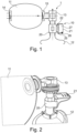
- a ventilation system 1 for respiratory assistance of a patient 1 comprising a device 10 for analyzing the ventilatory efficiency of the patient which will be described below.
- the ventilation system 1 comprises a ventilation device 11, forming in this example a self-filling balloon. It is not departing from the scope of the invention if the ventilation device is different, for example consisting of a mechanical fan or a flexible balloon or other.
- the ventilation system 1 may be suitable for use such as continuous ventilation of a patient in respiratory distress, respiratory support of a patient in apnea, assistance of a patient in spontaneous ventilation or discontinuous ventilation of a patient in cardiac arrest or other use.
- the ventilation system 1 further comprises a ventilation interface 12 for connecting the ventilation system 1 to the patient, consisting in the illustrated example of non-invasive ventilation on a mask.
- the mask is intended to be applied to the patient's mouth and nose. It is not outside the scope of the invention if the ventilation interface 12 is constituted by invasive ventilation on a tracheal tube or any other supralaryngeal device.
- the ventilation system 1 further comprises a one-way exhalation valve 13 placed between the ventilation device 11 and the ventilation interface 12 to direct the air coming from the ventilation device 11 towards the ventilation interface 12 and to allow the air exhaled by the patient to escape into the atmosphere.
- a one-way exhalation valve 13 placed between the ventilation device 11 and the ventilation interface 12 to direct the air coming from the ventilation device 11 towards the ventilation interface 12 and to allow the air exhaled by the patient to escape into the atmosphere.
- the ventilation device 11 is provided with a non-return valve 14 which opens into the open air and which passes in the direction of the atmosphere towards the ventilation device 11.
- the ventilation system 1 also includes a one-way insufflation valve 15 which allows air to be supplied to the patient.
- the diagnostic device 10, the ventilation device 11, the ventilation interface 12, the exhalation valve 13 and the insufflation valve 15 are assembled together in a removable manner, for example by interlocking as schematically illustrated in the figure 1 , in a manner known per se.
- the diagnostic device 10 of the ventilatory efficiency comprises a bidirectional thermal mass sensor 20 capable of measuring in real time air flow rates during insufflation and expiration and an electronic box 21 connected to said sensor 20 by removable connection means 22 ensuring an electronic and mechanical connection.
- the bidirectional thermal mass sensor 20, also called thermal mass flow meter, can be single-use or autoclavable. It is intended to be connected as visible on the Figures 1 and 2 , on one side, between the insufflation valve 15 of the ventilation device 11 and the expiration valve 13, and, on the other side, the ventilation interface 12.
- the sensor 20 makes it possible to measure the flow rates and volumes of inspired and expired air by measuring the specific heat capacity of the fluid, and by extension the quantity air passing through it during each ventilation cycle.
- the electronic box 21 is configured to receive and process data relating to the air flow rates measured by the sensor 20.
- the diagnostic device 10 does not include any other sensor, but it could include others, for example a pressure sensor and/or a CO2 concentration sensor in the air, without departing from the scope of the invention.
- the electronic housing 21 of the diagnostic device 10 comprises a data processing center, including a computer part or “hardware” and a software part or “software”, a user interface comprising a display device and data entry means or control interface, and power supply means such as one or more batteries.
- the electronic housing 21 makes it possible to ensure the interpretation of the ventilation curves and to display, for the rescuer, the important information related to the effectiveness of the ventilation and various alert messages. If the effectiveness of the ventilation is considered inadequate or harmful for the patient, the diagnostic device 10 makes it possible to identify the main causes of this lack of effectiveness and sends specific alert messages to the rescuer.
- the electronic box 21 comprises, in this example, as visible in the figure 1 , a light-emitting diode 25 or LED enabling the display of a visual alarm and a reset button 26, as well as a display device 27 shown in the figure 3 allowing the display of different types of alerts and messages depending on the efficiency analysis carried out by the electronic box 21.
- the electronic box 21 may alternatively comprise or consist of a touch pad, a laptop, a smartphone running a specific application, and provided where appropriate with a hardware interface with the sensor(s) and other elements of the system.
- the exchange of information between the processing center and the sensor(s) and other elements of the system can be carried out by wired and/or wireless means.
- a measured tidal volume Vt of 450 ml can be read.
- the inspired and expired volumes are also displayed on the screen in the form of a bargraph 28, divided into three parts in this example, forming three zones of color 28a, 28b and 28c to indicate respectively whether the volume is insufficient (28a), effective (28b) or excessive (28c) depending on the physiological characteristics of the patient.
- the optimal ventilation frequencies determined by the data processing center are transmitted to the rescuer via a light and/or sound and/or tactile signal to provide the appropriate cadence.
- a light and/or sound and/or tactile signal to provide the appropriate cadence.
- an alert message 31 indicating that the ventilation frequency must be reduced appears.
- Leaks are in fact detected and calculated by measuring the difference between the volume insufflated and the volume exhaled at each ventilation cycle and/or noting a drop in insufflation pressure simultaneously with an increase in flow rates.
- a visual indicator 32 makes it possible to view the charge level of the battery(ies).
- this diagnostic device 10 for each ventilation cycle, there is feedback provided by the electronic box 21 to the rescuer on the value of the main ventilation parameters and on their conformity with regard to the physical and physiological characteristics of the patient and the recommendations of the ILCOR (for International Liaison Committee On Resuscitation).
- the measurement of the volumes insufflated and expired carried out using the sensor 20 placed upstream of the ventilation interface 12 makes it possible, after processing by the data processing center of the electronic box 21, to estimate and display the tidal volume, i.e. the quantity of air actually supplying the patient's lungs, as well as the leaks at each ventilation cycle.
- the measurement of the flow rates also makes it possible to detect the different phases of the ventilation cycle using specific triggers.
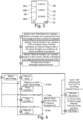
- FIGS. 4 to 7 illustrate the steps of the method of ventilating a patient using the ventilation system 1, in accordance with the invention.
- the method of ventilating a patient using the ventilation system 1 comprises a step 1 consisting, for the rescuer, in using the user interface, in particular the input means, to select or indicate a physical and/or physiological characteristic of the patient in the electronic box 21, in particular the size of the patient.
- the data processing center which recovers the characteristic, is then configured to automatically define the lung capacity of the patient and the appropriate tidal volume range (Vt), i.e. a minimum threshold and a maximum tidal volume threshold.
- the rescuer can select or indicate a ventilation characteristic, including the type of ventilation, for example, a choice between cardiopulmonary resuscitation (CPR) or ventilation alone.
- CPR cardiopulmonary resuscitation
- the data center then automatically defines the flow filtering level and trigger values for detecting inspiratory and expiratory phases.
- the rescuer can select another ventilation characteristic, for example the ventilation mode to choose between invasive or non-invasive ventilation.
- the data processing center then automatically defines the tolerance range for leak volumes, i.e. a maximum leak volume threshold.
- a step 4 the main screen of the display device 27 lights up and the main program of the data processing center starts.
- a step 5 the flow rate is measured using the sensor 20 so as to detect a pause phase 6, an inspiratory phase 7, an expiratory phase 8 and to perform a calculation phase 9.
- a step 6bis consisting of a detection of a positive flow rate generating the resetting of the clock, which makes it possible to detect that one is in the inspiratory phase.
- a negative flow rate is detected in a step 7bis, which makes it possible to say that one is in the expiratory phase.
- the flow rate, detected in a step 8bis is zero, which makes it possible to trigger the calculation phase 9.
- the cycle time (Tcycle) and the ventilation frequency (Fr) are measured in step 10.
- This inspiratory phase 7 includes the measurement of the inspiratory time T i 71. If the inspiratory time T i is greater than a predetermined duration, for example 4 seconds, a message 72 indicating "no expiration" in English (i.e. no expiration) is issued. It should be noted that inspiration generally lasts between 0.5 and 2s. Thus, if no expiration is detected after a predetermined duration greater than 2s, for example greater than 4s after the start of insufflation, message 72 is displayed.
- a predetermined duration for example 4 seconds
- the flow rate measurement in a step 73, is carried out and the flow rate is integrated over the respiratory time T i , which makes it possible, in a step 74, to calculate the insufflated or inspiratory volume V i and, in a step 75, to display the inspiratory volume V i and the rise of the bargraph 28.
- a step 76 the insufflation pressure is measured, in a step 77, the maximum pressure P peak is measured and, in a step 78, the display of this maximum pressure P peak is carried out.
- the process during the expiratory phase 8 is detailed on the figure 6 .
- the expiratory time T e is measured in a step 81.
- the flow rate is measured, in a step 82, and the theoretical expiratory time TeTh is calculated.
- the calculation of TeTh is carried out by evaluating the patient's expiratory time constant which is equal to 5*R*C, with R: pulmonary resistance and C: pulmonary compliance. TeTh can also be anticipated by exponential regression of the expiratory flow curve.
- the flow rate is then integrated over the expiratory time T e to deduce the calculation of the expiratory volume V e in a step 84.
- the bar graph 28 is gradually lowered over the duration TeTh in a step 85.
- the bar graph 28 is lowered directly proportional to V e in a step 86.
- a step 87 the CO 2 concentration is measured and the quantity of CO 2 exhaled EtCO 2 is displayed, for example using a measurement carried out by an optional sensor placed between the sensor 20 and the interface 12.
- a sensor is for example of the NDIR type (for “NonDispersive InfraRed”, in English, operating by non-dispersive absorption in the infrared), allowing a measurement by infrared spectroscopy.
- a step 88 the positive pressure at the end of expiration, noted PEEP for “Positive End Expiratory Pressure” in English, is measured and displayed.
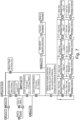
- a step 96 the pause time T p is also measured and, using the measurement of the ventilation frequency Fr, the size of the patient, the type of ventilation and the ventilation mode and the calculations carried out in steps 94 and 95 in particular, in a step 97, the pulmonary model is defined as well as the efficiency thresholds and ventilation parameters and the efficiency of the ventilation is analyzed.
- step 98 If the leak volume V leaks is greater than a predetermined maximum threshold, then, in a step 98, an alarm message “leaks” or “leaks” 30 is displayed. If the leak volume V leaks is less than said predetermined maximum threshold, in a step 99, the alarm message 30 is extinguished.
- a “high ventilation frequency” or “High Fr” alarm message is displayed, but if the ventilation frequency is less than the predefined maximum threshold, then, in a step 911, the alarm message is extinguished.
- the ventilation frequency Fr is less than a predefined minimum threshold, then, in a step 912, the “low ventilation frequency” or “low Fr” alarm message is displayed, but if the ventilation frequency Fr is greater than said predefined minimum threshold, then, in a step 913, the alarm message is extinguished.
- the alarm message “tidal volume high” or “High Vt” but if the tidal volume Vt is lower than this predetermined maximum threshold, then, in a step 915, the alarm message is extinguished. If the tidal volume Vt is lower than a predetermined minimum threshold, then, in a step 916, the alarm message "low tidal volume” or "low Vt” is displayed. When the tidal volume Vt is higher than a predetermined minimum threshold, then, in a step 917, the alarm message is extinguished.
- a green light-emitting diode 25 and the emission of an audible signal are carried out when the cycle time is greater than a constant included in a predetermined range of values, for example between 5 and 7 seconds, and the end of the expiratory phase is detected, or the cycle time exceeds a predetermined threshold value, for example 7 seconds.
- This audible and visual signal makes it possible to indicate to the rescuer the appropriate time for insufflation.
- the visual indicator such as a red light-emitting diode 25 is lit to warn the rescuer.
- the adequate range of the insufflated volume Vi is determined during steps 1 and 97.
- the volume Vi is adequate if the leaks are zero. Otherwise, the adequate volume is corrected according to the leaks.
- the optimal cycle time is based on the patient's lung characteristics such as pulmonary compliance and resistance.
- the leak volume can also be expressed as a percentage of the insufflated volume and has a predetermined maximum threshold, for example between approximately 20% and 40% of the insufflated volume.
- the maximum respiratory rate threshold Fr is for example between approximately 12 and 20 cycles per minute and the minimum ventilation rate threshold Fr is for example between approximately 8 and 12 cycles per minute.
- the predetermined maximum threshold is for example between approximately 500 ml and 700 ml and the predetermined minimum threshold is for example between approximately 300 ml and 500 ml.
- the rescuer can immediately have information on the volume of leaks, the ventilation frequency Fr, the tidal volume Vt and influence very quickly the parameter(s) to be corrected, if necessary, in order to restore optimal ventilation for the patient.
- the iteration of the steps of the method at each ventilation cycle of the patient allows the rescuer to adapt permanently to the evolution of the clinical condition of the patient and to modulate the parameters indicated on the display device 27, without having in-depth knowledge of the ventilation system or respiratory physiology.
- the system may be adapted for pediatric or neonatal use and the thresholds described above may change accordingly.
Landscapes
- Health & Medical Sciences (AREA)
- Life Sciences & Earth Sciences (AREA)
- General Health & Medical Sciences (AREA)
- Veterinary Medicine (AREA)
- Engineering & Computer Science (AREA)
- Biomedical Technology (AREA)
- Heart & Thoracic Surgery (AREA)
- Public Health (AREA)
- Animal Behavior & Ethology (AREA)
- Pulmonology (AREA)
- Emergency Medicine (AREA)
- Anesthesiology (AREA)
- Hematology (AREA)
- Physics & Mathematics (AREA)
- Biophysics (AREA)
- Pathology (AREA)
- Medical Informatics (AREA)
- Molecular Biology (AREA)
- Surgery (AREA)
- Physiology (AREA)
- Critical Care (AREA)
- Measurement Of The Respiration, Hearing Ability, Form, And Blood Characteristics Of Living Organisms (AREA)
Applications Claiming Priority (2)
| Application Number | Priority Date | Filing Date | Title |
|---|---|---|---|
| FR1555220A FR3036944B1 (fr) | 2015-06-08 | 2015-06-08 | Dispositif de diagnostic de l'efficacite de la ventilation d'un patient et procede de ventilation d'un patient |
| PCT/EP2016/062162 WO2016198275A1 (fr) | 2015-06-08 | 2016-05-30 | Dispositif de diagnostic de l'efficacite de la ventilation d'un patient et procede pour determiner l'efficacite ventilatoire d'un patient |
Publications (2)
| Publication Number | Publication Date |
|---|---|
| EP3302235A1 EP3302235A1 (fr) | 2018-04-11 |
| EP3302235B1 true EP3302235B1 (fr) | 2025-01-29 |
Family
ID=54478104
Family Applications (1)
| Application Number | Title | Priority Date | Filing Date |
|---|---|---|---|
| EP16729808.2A Active EP3302235B1 (fr) | 2015-06-08 | 2016-05-30 | Dispositif de diagnostic de l'efficacite de la ventilation d'un patient et procede pour determiner l'efficacite ventilatoire d'un patient |
Country Status (7)
Families Citing this family (14)
| Publication number | Priority date | Publication date | Assignee | Title |
|---|---|---|---|---|
| US20220111167A1 (en) * | 2015-06-08 | 2022-04-14 | Archeon | Device for diagnosing the efficacy of ventilation of a patient and method for determining the ventilatory efficacy of a patient |
| US11433211B2 (en) * | 2016-03-17 | 2022-09-06 | Zoll Medical Corporation | Flow sensor for ventilation |
| US11433202B2 (en) * | 2017-12-18 | 2022-09-06 | Koninklijke Philips N.V. | Interactive guidance related to a subject's expiratory flow limitation results |
| EP3787587B1 (en) | 2018-05-03 | 2025-01-08 | Umbulizer LLC | Ventilation apparatus |
| FR3088187A1 (fr) | 2018-11-09 | 2020-05-15 | Archeon | Appareils d'assistance a la realisation d'une procedure de soins d'urgence, systeme d'assistance a la reanimation cardiopulmonaire synchronisee et procede associe |
| US12274825B2 (en) | 2018-12-07 | 2025-04-15 | University Of Cincinnati | Rescue breathing device |
| CN109481806B (zh) * | 2018-12-21 | 2024-12-27 | 南京市第一医院 | 智能操作的简易人工呼吸器 |
| JP7449066B2 (ja) * | 2019-10-11 | 2024-03-13 | 日本光電工業株式会社 | 生体情報処理システム、発光装置及び生体情報処理装置 |
| US20230131417A1 (en) * | 2020-02-18 | 2023-04-27 | Rush University Medical Center | Device to monitor and alarm manual ventilation parameters during cardiopulmonary resuscitation |
| FR3118694B1 (fr) | 2021-01-08 | 2024-05-10 | Air Liquide Medical Systems | Boitier autonome de monitorage d’une ventilation délivrée pendant une réanimation cardio-pulmonaire |
| US20220313929A1 (en) * | 2021-03-30 | 2022-10-06 | Zoll Medical Corporation | Closed loop control in mechanical ventilation |
| US20220395653A1 (en) | 2021-06-15 | 2022-12-15 | Stryker Corporation | Systems and methods for airway management |
| AU2023409020A1 (en) | 2022-12-21 | 2025-07-03 | Stryker Corporation | Compression analysis via airway parameters |
| CN118845089B (zh) * | 2024-09-24 | 2024-12-13 | 海菲尔(江苏)生物科技有限公司 | 一种肠道微生态甲烷氢呼气检测装置 |
Citations (1)
| Publication number | Priority date | Publication date | Assignee | Title |
|---|---|---|---|---|
| FR2988004A1 (fr) * | 2012-03-19 | 2013-09-20 | Schrader | Dispositif pour insufflateur manuel et insufflateur comportant ce dispositif |
Family Cites Families (15)
| Publication number | Priority date | Publication date | Assignee | Title |
|---|---|---|---|---|
| US6463930B2 (en) * | 1995-12-08 | 2002-10-15 | James W. Biondi | System for automatically weaning a patient from a ventilator, and method thereof |
| US6158432A (en) * | 1995-12-08 | 2000-12-12 | Cardiopulmonary Corporation | Ventilator control system and method |
| JP4602539B2 (ja) * | 2000-12-06 | 2010-12-22 | 帝人株式会社 | 呼吸測定装置 |
| GB0509371D0 (en) * | 2005-05-07 | 2005-06-15 | Smiths Group Plc | Resuscitators |
| US8394040B2 (en) * | 2006-12-15 | 2013-03-12 | Laerdal Medical As | Signal processing device for providing feedback on chest compression in CPR |
| US20080236585A1 (en) | 2007-03-29 | 2008-10-02 | Caldyne Inc. | Indicating device for a ventilator |
| EP2164442B1 (en) * | 2007-05-30 | 2019-12-25 | Gilbert Jacobus Kuypers | Improvements to electrically operable resuscitators |
| US8656913B2 (en) * | 2007-06-05 | 2014-02-25 | Allied Healthcare Products, Inc. | Ventilator apparatus |
| US10252020B2 (en) * | 2008-10-01 | 2019-04-09 | Breathe Technologies, Inc. | Ventilator with biofeedback monitoring and control for improving patient activity and health |
| CN102711889B (zh) * | 2010-01-22 | 2015-06-03 | 皇家飞利浦电子股份有限公司 | 自动控制的通气系统和方法 |
| US8607791B2 (en) * | 2010-06-30 | 2013-12-17 | Covidien Lp | Ventilator-initiated prompt regarding auto-PEEP detection during pressure ventilation |
| KR101287171B1 (ko) | 2010-09-27 | 2013-07-17 | 김도희 | 적정공기환기를 위한 bvm |
| CN103619390B (zh) * | 2011-05-23 | 2016-01-13 | 佐尔医药公司 | 具有通气质量反馈单元的医疗通气系统 |
| WO2014078840A1 (en) | 2012-11-19 | 2014-05-22 | The General Hospital Corporation | A system and method for monitoring resuscitation or respiratory mechanics of a patient |
| US9446211B2 (en) * | 2013-03-14 | 2016-09-20 | Carefusion 2200, Inc. | Resuscitation device with onboard processor |
-
2015
- 2015-06-08 FR FR1555220A patent/FR3036944B1/fr active Active
-
2016
- 2016-05-30 ES ES16729808T patent/ES3024182T3/es active Active
- 2016-05-30 JP JP2017564354A patent/JP7093182B2/ja active Active
- 2016-05-30 EP EP16729808.2A patent/EP3302235B1/fr active Active
- 2016-05-30 US US15/580,526 patent/US20180160970A1/en not_active Abandoned
- 2016-05-30 DK DK16729808.2T patent/DK3302235T3/da active
- 2016-05-30 WO PCT/EP2016/062162 patent/WO2016198275A1/fr active Application Filing
-
2022
- 2022-01-06 JP JP2022001334A patent/JP2022058525A/ja active Pending
Patent Citations (1)
| Publication number | Priority date | Publication date | Assignee | Title |
|---|---|---|---|---|
| FR2988004A1 (fr) * | 2012-03-19 | 2013-09-20 | Schrader | Dispositif pour insufflateur manuel et insufflateur comportant ce dispositif |
Also Published As
| Publication number | Publication date |
|---|---|
| WO2016198275A1 (fr) | 2016-12-15 |
| JP2022058525A (ja) | 2022-04-12 |
| FR3036944B1 (fr) | 2021-01-22 |
| FR3036944A1 (fr) | 2016-12-09 |
| US20180160970A1 (en) | 2018-06-14 |
| EP3302235A1 (fr) | 2018-04-11 |
| JP7093182B2 (ja) | 2022-06-29 |
| ES3024182T3 (en) | 2025-06-04 |
| DK3302235T3 (da) | 2025-05-05 |
| JP2018524064A (ja) | 2018-08-30 |
Similar Documents
| Publication | Publication Date | Title |
|---|---|---|
| EP3302235B1 (fr) | Dispositif de diagnostic de l'efficacite de la ventilation d'un patient et procede pour determiner l'efficacite ventilatoire d'un patient | |
| US20250025657A1 (en) | Assistive capnography device | |
| US7211049B2 (en) | Breath measurement | |
| JP6246937B2 (ja) | 呼吸分析およびトレーニングアセンブリ | |
| US20220022772A1 (en) | Handheld respiratory diagnostic, training, and therapy devices and methods | |
| WO2008081449A2 (en) | Capngoraphy device and method | |
| FR2906450A1 (fr) | Systeme et procede de detection d'evenements respiratoires | |
| US10966632B2 (en) | Method and device for determining the health of a subject | |
| JP2023509632A (ja) | 呼気センサの測定方法及び装置 | |
| EP4069077B1 (en) | Systems and methods for metabolic monitoring | |
| EP3639735B1 (fr) | Appareil de monitorage ou de ventilation pour réanimation cardio-pulmonaire avec détermination d'un indice d'ouverture des voies respiratoires | |
| CN107510449B (zh) | 心率分析方法及智能穿戴设备 | |
| EP3511043B1 (fr) | Appareil de ventilation pour réanimation cardio-pulmonaire avec monitorage et affichage de la valeur maximale de co2 mesurée | |
| CA2783954C (fr) | Dispositif medical de suivi de l'observance de patients apneiques | |
| EP3643229B1 (fr) | Appareil de monitorage cardiaque pour réanimation cardio-pulmonaire avec affichage des teneurs maximale ou moyenne en co2 | |
| WO2019243141A1 (en) | Leakage detection of face masks | |
| CA2600997C (fr) | Dispositif d'autocontrole de sa respiration par un individu en vue de l'assistance au pilotage d'une unite de radiotherapie ou d'imagerie | |
| GB2509922A (en) | Measuring Respiratory Exchange Ratio (RER) using a portion of expired breath | |
| EP1909646A1 (en) | Improvements in and relating to breath measurement | |
| CN120227627A (zh) | 一种智能化肺功能呼吸训练仪 |
Legal Events
| Date | Code | Title | Description |
|---|---|---|---|
| STAA | Information on the status of an ep patent application or granted ep patent |
Free format text: STATUS: THE INTERNATIONAL PUBLICATION HAS BEEN MADE |
|
| PUAI | Public reference made under article 153(3) epc to a published international application that has entered the european phase |
Free format text: ORIGINAL CODE: 0009012 |
|
| STAA | Information on the status of an ep patent application or granted ep patent |
Free format text: STATUS: REQUEST FOR EXAMINATION WAS MADE |
|
| 17P | Request for examination filed |
Effective date: 20180108 |
|
| AK | Designated contracting states |
Kind code of ref document: A1 Designated state(s): AL AT BE BG CH CY CZ DE DK EE ES FI FR GB GR HR HU IE IS IT LI LT LU LV MC MK MT NL NO PL PT RO RS SE SI SK SM TR |
|
| AX | Request for extension of the european patent |
Extension state: BA ME |
|
| RIN1 | Information on inventor provided before grant (corrected) |
Inventor name: NITA, FLORIN, DAN Inventor name: PAZART, LIONEL Inventor name: DE LUCA, ALBAN Inventor name: VINCHANT, JEAN-FRANCOIS Inventor name: KHOURY, ABDO Inventor name: CAPELLIER, GILLES Inventor name: SALL, FATIMATA, SEYDOU Inventor name: SAILLARD, PIERRE-EDOUARD |
|
| DAV | Request for validation of the european patent (deleted) | ||
| DAX | Request for extension of the european patent (deleted) | ||
| RAP1 | Party data changed (applicant data changed or rights of an application transferred) |
Owner name: CENTRE HOSPITALIER REGIONAL UNIVERSITAIRE DE BESAN Owner name: UNIVERSITE DE FRANCHE-COMTE Owner name: ARCHEON |
|
| STAA | Information on the status of an ep patent application or granted ep patent |
Free format text: STATUS: EXAMINATION IS IN PROGRESS |
|
| 17Q | First examination report despatched |
Effective date: 20220401 |
|
| GRAP | Despatch of communication of intention to grant a patent |
Free format text: ORIGINAL CODE: EPIDOSNIGR1 |
|
| STAA | Information on the status of an ep patent application or granted ep patent |
Free format text: STATUS: GRANT OF PATENT IS INTENDED |
|
| INTG | Intention to grant announced |
Effective date: 20240927 |
|
| RAP3 | Party data changed (applicant data changed or rights of an application transferred) |
Owner name: CENTRE HOSPITALIER REGIONAL UNIVERSITAIRE DEBESANCON Owner name: UNIVERSITE DE FRANCHE-COMTE Owner name: ARCHEON |
|
| RIN1 | Information on inventor provided before grant (corrected) |
Inventor name: VINCHANT, JEAN-FRANCOIS Inventor name: NITA, FLORIN, DAN Inventor name: SAILLARD, PIERRE-EDOUARD Inventor name: CAPELLIER, GILLES Inventor name: PAZART, LIONEL Inventor name: SALL, FATIMATA, SEYDOU Inventor name: DE LUCA, ALBAN Inventor name: KHOURY, ABDO |
|
| GRAS | Grant fee paid |
Free format text: ORIGINAL CODE: EPIDOSNIGR3 |
|
| GRAA | (expected) grant |
Free format text: ORIGINAL CODE: 0009210 |
|
| STAA | Information on the status of an ep patent application or granted ep patent |
Free format text: STATUS: THE PATENT HAS BEEN GRANTED |
|
| AK | Designated contracting states |
Kind code of ref document: B1 Designated state(s): AL AT BE BG CH CY CZ DE DK EE ES FI FR GB GR HR HU IE IS IT LI LT LU LV MC MK MT NL NO PL PT RO RS SE SI SK SM TR |
|
| REG | Reference to a national code |
Ref country code: GB Ref legal event code: FG4D Free format text: NOT ENGLISH |
|
| REG | Reference to a national code |
Ref country code: CH Ref legal event code: EP |
|
| REG | Reference to a national code |
Ref country code: DE Ref legal event code: R096 Ref document number: 602016091081 Country of ref document: DE |
|
| REG | Reference to a national code |
Ref country code: IE Ref legal event code: FG4D Free format text: LANGUAGE OF EP DOCUMENT: FRENCH |
|
| REG | Reference to a national code |
Ref country code: DK Ref legal event code: T3 Effective date: 20250429 |
|
| REG | Reference to a national code |
Ref country code: NL Ref legal event code: FP |
|
| P01 | Opt-out of the competence of the unified patent court (upc) registered |
Free format text: CASE NUMBER: APP_19857/2025 Effective date: 20250425 |
|
| REG | Reference to a national code |
Ref country code: ES Ref legal event code: FG2A Ref document number: 3024182 Country of ref document: ES Kind code of ref document: T3 Effective date: 20250604 |
|
| PGFP | Annual fee paid to national office [announced via postgrant information from national office to epo] |
Ref country code: NL Payment date: 20250528 Year of fee payment: 10 |
|
| PG25 | Lapsed in a contracting state [announced via postgrant information from national office to epo] |
Ref country code: RS Free format text: LAPSE BECAUSE OF FAILURE TO SUBMIT A TRANSLATION OF THE DESCRIPTION OR TO PAY THE FEE WITHIN THE PRESCRIBED TIME-LIMIT Effective date: 20250429 |
|
| PG25 | Lapsed in a contracting state [announced via postgrant information from national office to epo] |
Ref country code: FI Free format text: LAPSE BECAUSE OF FAILURE TO SUBMIT A TRANSLATION OF THE DESCRIPTION OR TO PAY THE FEE WITHIN THE PRESCRIBED TIME-LIMIT Effective date: 20250129 |
|
| PG25 | Lapsed in a contracting state [announced via postgrant information from national office to epo] |
Ref country code: PL Free format text: LAPSE BECAUSE OF FAILURE TO SUBMIT A TRANSLATION OF THE DESCRIPTION OR TO PAY THE FEE WITHIN THE PRESCRIBED TIME-LIMIT Effective date: 20250129 |
|
| PGFP | Annual fee paid to national office [announced via postgrant information from national office to epo] |
Ref country code: DE Payment date: 20250617 Year of fee payment: 10 |
|
| PGFP | Annual fee paid to national office [announced via postgrant information from national office to epo] |
Ref country code: ES Payment date: 20250620 Year of fee payment: 10 Ref country code: GB Payment date: 20250625 Year of fee payment: 10 Ref country code: DK Payment date: 20250527 Year of fee payment: 10 |
|
| REG | Reference to a national code |
Ref country code: LT Ref legal event code: MG9D |
|
| PG25 | Lapsed in a contracting state [announced via postgrant information from national office to epo] |
Ref country code: IS Free format text: LAPSE BECAUSE OF FAILURE TO SUBMIT A TRANSLATION OF THE DESCRIPTION OR TO PAY THE FEE WITHIN THE PRESCRIBED TIME-LIMIT Effective date: 20250529 |
|
| PGFP | Annual fee paid to national office [announced via postgrant information from national office to epo] |
Ref country code: NO Payment date: 20250530 Year of fee payment: 10 |
|
| PGFP | Annual fee paid to national office [announced via postgrant information from national office to epo] |
Ref country code: BE Payment date: 20250528 Year of fee payment: 10 Ref country code: IT Payment date: 20250507 Year of fee payment: 10 |
|
| REG | Reference to a national code |
Ref country code: AT Ref legal event code: MK05 Ref document number: 1762608 Country of ref document: AT Kind code of ref document: T Effective date: 20250129 |
|
| PG25 | Lapsed in a contracting state [announced via postgrant information from national office to epo] |
Ref country code: HR Free format text: LAPSE BECAUSE OF FAILURE TO SUBMIT A TRANSLATION OF THE DESCRIPTION OR TO PAY THE FEE WITHIN THE PRESCRIBED TIME-LIMIT Effective date: 20250129 |
|
| PG25 | Lapsed in a contracting state [announced via postgrant information from national office to epo] |
Ref country code: PT Free format text: LAPSE BECAUSE OF FAILURE TO SUBMIT A TRANSLATION OF THE DESCRIPTION OR TO PAY THE FEE WITHIN THE PRESCRIBED TIME-LIMIT Effective date: 20250529 Ref country code: LV Free format text: LAPSE BECAUSE OF FAILURE TO SUBMIT A TRANSLATION OF THE DESCRIPTION OR TO PAY THE FEE WITHIN THE PRESCRIBED TIME-LIMIT Effective date: 20250129 |
|
| PGFP | Annual fee paid to national office [announced via postgrant information from national office to epo] |
Ref country code: FR Payment date: 20250530 Year of fee payment: 10 |
|
| PG25 | Lapsed in a contracting state [announced via postgrant information from national office to epo] |
Ref country code: GR Free format text: LAPSE BECAUSE OF FAILURE TO SUBMIT A TRANSLATION OF THE DESCRIPTION OR TO PAY THE FEE WITHIN THE PRESCRIBED TIME-LIMIT Effective date: 20250430 Ref country code: BG Free format text: LAPSE BECAUSE OF FAILURE TO SUBMIT A TRANSLATION OF THE DESCRIPTION OR TO PAY THE FEE WITHIN THE PRESCRIBED TIME-LIMIT Effective date: 20250129 |
|
| PGFP | Annual fee paid to national office [announced via postgrant information from national office to epo] |
Ref country code: CH Payment date: 20250625 Year of fee payment: 10 |
|
| PG25 | Lapsed in a contracting state [announced via postgrant information from national office to epo] |
Ref country code: AT Free format text: LAPSE BECAUSE OF FAILURE TO SUBMIT A TRANSLATION OF THE DESCRIPTION OR TO PAY THE FEE WITHIN THE PRESCRIBED TIME-LIMIT Effective date: 20250129 |
|
| PGFP | Annual fee paid to national office [announced via postgrant information from national office to epo] |
Ref country code: IE Payment date: 20250521 Year of fee payment: 10 |