EP3302197B1 - Blender with a sealing gasket comprising ribs - Google Patents
Blender with a sealing gasket comprising ribs Download PDFInfo
- Publication number
- EP3302197B1 EP3302197B1 EP16724055.5A EP16724055A EP3302197B1 EP 3302197 B1 EP3302197 B1 EP 3302197B1 EP 16724055 A EP16724055 A EP 16724055A EP 3302197 B1 EP3302197 B1 EP 3302197B1
- Authority
- EP
- European Patent Office
- Prior art keywords
- blender
- rib
- container
- sealing gasket
- bottom part
- Prior art date
- Legal status (The legal status is an assumption and is not a legal conclusion. Google has not performed a legal analysis and makes no representation as to the accuracy of the status listed.)
- Active
Links
- 238000007789 sealing Methods 0.000 title claims description 46
- 230000006835 compression Effects 0.000 claims description 13
- 238000007906 compression Methods 0.000 claims description 13
- 239000000463 material Substances 0.000 claims description 6
- 238000010438 heat treatment Methods 0.000 claims description 4
- 238000002156 mixing Methods 0.000 description 22
- 235000012041 food component Nutrition 0.000 description 11
- 239000005417 food ingredient Substances 0.000 description 11
- 239000011521 glass Substances 0.000 description 7
- 238000004519 manufacturing process Methods 0.000 description 5
- 238000004140 cleaning Methods 0.000 description 4
- 230000008878 coupling Effects 0.000 description 3
- 238000010168 coupling process Methods 0.000 description 3
- 238000005859 coupling reaction Methods 0.000 description 3
- 239000007788 liquid Substances 0.000 description 3
- 230000015572 biosynthetic process Effects 0.000 description 2
- 238000010411 cooking Methods 0.000 description 2
- 235000013305 food Nutrition 0.000 description 2
- 238000005755 formation reaction Methods 0.000 description 2
- 238000000465 moulding Methods 0.000 description 2
- 238000013459 approach Methods 0.000 description 1
- 230000001419 dependent effect Effects 0.000 description 1
- 235000013399 edible fruits Nutrition 0.000 description 1
- 238000000034 method Methods 0.000 description 1
- 239000008267 milk Substances 0.000 description 1
- 210000004080 milk Anatomy 0.000 description 1
- 235000013336 milk Nutrition 0.000 description 1
- 239000002245 particle Substances 0.000 description 1
- 239000004033 plastic Substances 0.000 description 1
- 238000009987 spinning Methods 0.000 description 1
- XLYOFNOQVPJJNP-UHFFFAOYSA-N water Substances O XLYOFNOQVPJJNP-UHFFFAOYSA-N 0.000 description 1
Images


Classifications
-
- A—HUMAN NECESSITIES
- A47—FURNITURE; DOMESTIC ARTICLES OR APPLIANCES; COFFEE MILLS; SPICE MILLS; SUCTION CLEANERS IN GENERAL
- A47J—KITCHEN EQUIPMENT; COFFEE MILLS; SPICE MILLS; APPARATUS FOR MAKING BEVERAGES
- A47J43/00—Implements for preparing or holding food, not provided for in other groups of this subclass
- A47J43/04—Machines for domestic use not covered elsewhere, e.g. for grinding, mixing, stirring, kneading, emulsifying, whipping or beating foodstuffs, e.g. power-driven
- A47J43/07—Parts or details, e.g. mixing tools, whipping tools
- A47J43/0716—Parts or details, e.g. mixing tools, whipping tools for machines with tools driven from the lower side
-
- A—HUMAN NECESSITIES
- A47—FURNITURE; DOMESTIC ARTICLES OR APPLIANCES; COFFEE MILLS; SPICE MILLS; SUCTION CLEANERS IN GENERAL
- A47J—KITCHEN EQUIPMENT; COFFEE MILLS; SPICE MILLS; APPARATUS FOR MAKING BEVERAGES
- A47J43/00—Implements for preparing or holding food, not provided for in other groups of this subclass
- A47J43/04—Machines for domestic use not covered elsewhere, e.g. for grinding, mixing, stirring, kneading, emulsifying, whipping or beating foodstuffs, e.g. power-driven
- A47J43/046—Machines for domestic use not covered elsewhere, e.g. for grinding, mixing, stirring, kneading, emulsifying, whipping or beating foodstuffs, e.g. power-driven with tools driven from the bottom side
-
- A—HUMAN NECESSITIES
- A47—FURNITURE; DOMESTIC ARTICLES OR APPLIANCES; COFFEE MILLS; SPICE MILLS; SUCTION CLEANERS IN GENERAL
- A47J—KITCHEN EQUIPMENT; COFFEE MILLS; SPICE MILLS; APPARATUS FOR MAKING BEVERAGES
- A47J43/00—Implements for preparing or holding food, not provided for in other groups of this subclass
- A47J43/04—Machines for domestic use not covered elsewhere, e.g. for grinding, mixing, stirring, kneading, emulsifying, whipping or beating foodstuffs, e.g. power-driven
- A47J43/07—Parts or details, e.g. mixing tools, whipping tools
- A47J43/0716—Parts or details, e.g. mixing tools, whipping tools for machines with tools driven from the lower side
- A47J43/0722—Mixing, whipping or cutting tools
-
- A—HUMAN NECESSITIES
- A47—FURNITURE; DOMESTIC ARTICLES OR APPLIANCES; COFFEE MILLS; SPICE MILLS; SUCTION CLEANERS IN GENERAL
- A47J—KITCHEN EQUIPMENT; COFFEE MILLS; SPICE MILLS; APPARATUS FOR MAKING BEVERAGES
- A47J43/00—Implements for preparing or holding food, not provided for in other groups of this subclass
- A47J43/04—Machines for domestic use not covered elsewhere, e.g. for grinding, mixing, stirring, kneading, emulsifying, whipping or beating foodstuffs, e.g. power-driven
- A47J43/07—Parts or details, e.g. mixing tools, whipping tools
- A47J43/0727—Mixing bowls
-
- F—MECHANICAL ENGINEERING; LIGHTING; HEATING; WEAPONS; BLASTING
- F16—ENGINEERING ELEMENTS AND UNITS; GENERAL MEASURES FOR PRODUCING AND MAINTAINING EFFECTIVE FUNCTIONING OF MACHINES OR INSTALLATIONS; THERMAL INSULATION IN GENERAL
- F16J—PISTONS; CYLINDERS; SEALINGS
- F16J15/00—Sealings
- F16J15/16—Sealings between relatively-moving surfaces
- F16J15/32—Sealings between relatively-moving surfaces with elastic sealings, e.g. O-rings
- F16J15/3204—Sealings between relatively-moving surfaces with elastic sealings, e.g. O-rings with at least one lip
- F16J15/3232—Sealings between relatively-moving surfaces with elastic sealings, e.g. O-rings with at least one lip having two or more lips
-
- B—PERFORMING OPERATIONS; TRANSPORTING
- B01—PHYSICAL OR CHEMICAL PROCESSES OR APPARATUS IN GENERAL
- B01F—MIXING, e.g. DISSOLVING, EMULSIFYING OR DISPERSING
- B01F35/00—Accessories for mixers; Auxiliary operations or auxiliary devices; Parts or details of general application
- B01F35/30—Driving arrangements; Transmissions; Couplings; Brakes
- B01F2035/35—Use of other general mechanical engineering elements in mixing devices
- B01F2035/351—Sealings
Landscapes
- Engineering & Computer Science (AREA)
- Mechanical Engineering (AREA)
- Food Science & Technology (AREA)
- General Engineering & Computer Science (AREA)
- Food-Manufacturing Devices (AREA)
Description
- The invention relates to a blender with a sealing gasket comprising ribs.
- The invention may be used in the field of food blending, in particular kitchen appliance blenders.
- Blenders are kitchen appliances which are designed for mixing or blending food ingredients such as fruit, milk and ice, into liquids. Blenders typically consist of a base, having a vertically positioned powerful a/c motor with a lower coupling, and a cylindrical jar located directly above the base. The jar has a rotatable blade assembly at the bottom with an upper coupling driven by the lower coupling. The blade assembly is usually mounted in a blade-holding component which forms the bottom of the jar with a water tight seal in between, and removable for easy cleaning.
- The blending performance of a blender is usually measured by the fineness of blended food ingredients after a limited time of blending. Critical for good performance of a blender is the diameter of the jar at blade height, but also the presence of turbulence-creating ribs of similar formations inside the jar, for example at blade assembly height. Such rib formations reduce spinning of liquid inside the jar, which thus enhances blending performance.
- For hygiene, cleaning and durability reasons, blenders usually have jar made of glass material.
- An example of a known
blender 100 is depicted inFig.1 . It comprises abase part 101 and ajar 102 made of glass arranged on thebase part 101. The bottom part of thejar 102 is closed by adetachable bottom part 103. A sealinggasket 104 is disposed between thedetachable bottom part 103 and thejar 102. Thejar 102 comprisesribs 105 extending upwards on the inside surface of thejar 102. Theribs 105 are made of glass and are moulded together with the wall of thejar 102. Ablade assembly 106 is disposed on thebottom part 103 and rotated by amotor assembly 107 disposed in thebase part 101. - When manufacturing a jar made of glass, to facilitate the manufacturing, it is preferred that the geometry is cylindrical and uniform, without large protruding ribs inside the jar. This creates a dilemma since the very same ribs are critical to obtain good blending performance. The width of the ribs can be reduced to facilitate the moulding during manufacturing, but to the detriment of blending performance.
-
US 3344829A discloses a gasket arrangement for blender containers which have removable bases. Such arrangement can prevent food particles from becoming trapped when the blender container is washed by simply rinsing and will function effectively whether the removable container base in used with a specially designed blender container or with a standard Mason jar. However, it cannot totally solve the above mentioned problems existed in the prior arts. - It is an object of the invention to propose a blender that mitigates and/or alleviates the above mentioned problems by providing an improved blending performance.
- The invention is defined by the independent claims. The dependent claims define advantageous embodiments.
- To this end, the blender according to the invention comprises:
- a base part,
- a container arranged on the base part, the container comprising a detachable bottom part,
- a sealing gasket arranged between the detachable bottom part and the container, characterized in that the sealing gasket comprising more than one rib extending upwards inside the container, wherein the more than one rib comprises a plurality of ribs distributed around an inner periphery of the sealing gasket.
- By having the ribs directly part of the sealing gasket, the jar can be made of glass without any ribs on the inside surface of the jar. The manufacturing of the glass jar is thus facilitated because the inside surface of the jar does not have protuberances. This also contributes to an easier cleaning of the inside jar by a user. Moreover, high blending performance of the blender is ensured by having some ribs still extending inside the jar. Since the sealing gasket is a removable part of the blender, this also contributes to an easier cleaning of the ribs by a user. Having a plurality of ribs improves the blending performance.
- Advantageously, the more than one rib extends along an internal surface of a lower portion of the container.
- Advantageously, the tab portion is arranged at an upper part of the more than one rib.
- Having the tab portion disposed at this position helps to retain the food ingredients in a lower part of the jar. This helps limit that the food ingredients splash upwards inside/outside the jar during blending, and also further improves the blending performance.
- Advantageously, the tab portion forms a truncated pyramid.
- This shape allows creating optimum turbulences of the food ingredients during blending.
- Advantageously, the sealing gasket comprises a ring element having a first surface facing the detachable bottom part and a second surface facing the container, wherein at least one of the first surface and the second surface comprises concentric compression ribs.
- The concentric compression ribs arranged on the ring element further improve the sealing between the detachable bottom part and the container.
- Advantageously, the sealing gasket and the more than one rib form a single element made of moulded rubber material.
- Moulding the ribs together with the sealing gasket allows an easy manufacturing of this assembly.
- Advantageously, the more than one rib has a height in the range [10 mm; 50 mm].
- This range of value contributes to obtaining optimal blending performance for kitchen appliance blenders.
- Advantageously, the more than one rib has a thickness in the range [3 mm; 15 mm].
- This range of value contributes to obtaining optimal blending performance for kitchen appliance blenders.
- Advantageously, the more than one rib has a width in the range [10 mm; 30 mm].
- This range of value contributes to obtaining optimal blending performance for kitchen appliance blenders.
- Advantageously, the blender further comprises a blade assembly comprising a plurality of blades and arranged on the bottom part and extending inside the container, and a gearing system to rotate the blade assembly. The more than one rib extends upwards inside the container up to a height where the plurality of blades connect, with a variation within a range of [-20%; +100%].
- Having the ribs extending upwards up to this range of values contributes to obtaining optimal blending performance.
- Advantageously, the blender further comprises a locking element to press the container, the sealing gasket and the detachable bottom part against each other.
- This allows maintaining all elements in place during blending, while ensuring sealing.
- Advantageously, the base part further comprises a heating element to transfer heat by conduction to the detachable bottom part.
- The heating element allows cooking the food ingredients being inside the jar, for example after blending, while having the possibility to easily detach the jar from the base after cooking.
- Detailed explanations and other aspects of the invention will be given below.
- Particular aspects of the invention will now be explained with reference to the embodiments described hereinafter and considered in connection with the accompanying drawings, in which identical parts or sub-steps are designated in the same manner:
-
Fig.1 depicts a blender according to the prior art, -
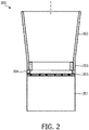
Fig.2 depicts a simplified view of a blender according to the invention, -
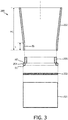
Fig.3 depicts an exploded view of a blender as depicted inFig.2 , -
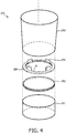
Fig.4 depicts a three-dimensional exploded view of a blender as depicted inFig.3 , -
Fig.5A, Fig.5B, Fig.5C, Fig.5D depict different embodiments of a sealing gasket according to the invention comprising a tab portion, -
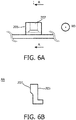
Fig.6A, Fig.6B depict zoomed-in views of a sealing gasket according to the invention comprising a tab portion taking the form of a truncated pyramid, -
Fig.7 depicts a three-dimensional zoomed-in view of a sealing gasket according to the invention, -
Fig.8A, Fig.8B, Fig.8C ,Fig.8D depict various embodiments of a sealing gasket according to the invention comprising concentric compression ribs, -
Fig.9A, Fig.9B , depict various embodiments of a sealing gasket according to the invention comprising outer ribs, -
Fig.10 depicts a blender according to the invention. -
Fig.2 depicts ablender 200 according to the invention. - The
blender 200 comprises abase part 201. Thebase part 201 is intended to receive the gearing system (not shown) to rotate a blade assembly (not shown) used to blend food ingredients. - The
blender 200 also comprises acontainer 202 arranged on thebase part 201. Thecontainer 202 corresponds to the jar in which food ingredients to be blended are put. - The
container 202 comprises a detachablebottom part 203. The detachablebottom part 203 is intended to close the bottom part of thecontainer 202. - The
blender 200 also comprises a sealinggasket 204 arranged between the detachablebottom part 203 and thecontainer 202. One function of the sealinggasket 204 is to ensure the sealing between the detachablebottom part 203 and thecontainer 202 to prevent food ingredients and liquid in thecontainer 202 from leaking outside thecontainer 202. - The sealing
gasket 204 also comprises more than onerib 205 extending upwards inside thecontainer 202. The rib(s) 205 aims to create turbulences among the food ingredients during blending, to improve the blending performance. The more than onerib 205 replaces the ribs made of glass and moulded together with the jar of the known blenders. -
Fig.3 depicts an exploded view of ablender 200 according to the invention, andFig.4 depicts a corresponding three-dimensional exploded view. Those figures illustrate the same elements as inFig.1 . The cross-section of theblender 200 is preferably circular. As illustrated inFig.3 , the more than onerib 205 extends along an internal surface IS of a lower portion L of thecontainer 202. The lower portion L corresponds to the bottom part of thecontainer 202 covering between 5% and 20% of the height H1 of thecontainer 202. The more than onerib 205 comprises a plurality of ribs distributed around an inner periphery IP of the sealinggasket 204. For example, as illustrated inFig.4 , a number of fourribs 205 is chosen. Advantageously, the ribs are regularly distributed around the inner periphery IP. For example, if a number of fourribs 205 is chosen, the ribs are distributed every 90 degrees around the inner periphery IP. -
Fig.5A, Fig.5B, Fig.5C, Fig.5D depict various embodiments of a sealing gasket according to the invention comprising atab portion 207. - Preferably, at least one of the more than one
rib 205 comprises atab portion 207 extending along a direction RD being radial compared to an inner periphery IP of the sealinggasket 204. The direction RD directs toward the center of the periphery IP. - Preferably, the
tab portion 207 is arranged at an upper part U of the at least one of the more than onerib 205. - For example, as depicted by
Fig.5A and Fig.5D , thetab portion 207 is at the most upper part of therib 205. - For example, as depicted by
Fig.5B and Fig.5C , thetab portion 207 is slightly below the most upper part of therib 205. - For example, as depicted by
Fig.5A and Fig.5B , thetab portion 207 takes the form of a cubic element. - For example, as depicted by
Fig.5C and Fig.5D , thetab portion 207 takes the form of a truncated pyramid. -
Fig.6A depicts a zoomed-in front view of atab portion 207 taking the form of a truncated pyramid as depicted byFig.5D , whileFig.6B depicts the corresponding zoomed-in lateral cross-section view. -
Fig.7 depicts a three-dimensional zoomed-in view of a sealinggasket 204 according to the invention. In this example, the sealinggasket 204 comprises fourribs 205. - Preferably, more than one
rib 205 has a height h1 in the range [10 mm; 50 mm]. - Preferably, more than one
rib 205 has a thickness e1 in the range [3 mm; 15 mm]. - Preferably, more than one
rib 205 has a width w1 in the range [10 mm; 30 mm]. - Those ranges of values are suitable for domestic appliances with a sealing
gasket 204 having an external diameter with dimension between 100 mm and 150 mm. - Preferably, as depicted in
Fig.7 , the sealinggasket 204 comprises aring element 206 having a first surface S1 facing the detachablebottom part 203 and a second surface S2 facing thecontainer 202. As depicted inFig.8A, Fig.8B, Fig.8C andFig.8D , at least one of the first surface S1 and the second surface S2 comprises concentric compression ribs CR1, CR2. - For example, as depicted in
Fig.8A , the compression ribs CR1 are on the first surface S1. The compression ribs CR1 aims to further improving the contact with thebottom part 203. - For example, as depicted in
Fig.8B , the compression ribs CR2 are on the second surface S2. The compression ribs CR2 aims to further improving the contact with thecontainer 202. A corresponding three-dimensional view is depicted inFig.8C . - For example, as depicted in
Fig.8D , the compression ribs CR1 are on the first surface S1, and the compression ribs CR2 are on the second surface S2. The compression ribs CR1 aims to further improving the contact with thebottom part 203. The compression ribs CR2 aims to further improving the contact with thecontainer 202. - Preferably, the sealing
gasket 204 and the more than onerib 205 form a single element made of moulded rubber material. Alternatively, the more than onerib 205 are glued or attached as separate elements, and are for example made of plastic material. - Preferably, as depicted in
Fig. 9A , the sealinggasket 204 further comprises a first outer rib OR1 at an outer periphery OP of the sealinggasket 204. The first outer rib OR1 extends along a first vertical direction VD1 towards the detachablebottom part 203. The circumference of the first outer rib OR1 is such that it surrounds the detachablebottom part 203. The first outer rib OR1 facilitates centering thebottom part 203 on the sealinggasket 204. - Preferably, as depicted in
Fig. 9B , the sealinggasket 204 further comprises a second outer rib OR2 at an outer periphery OP of the sealinggasket 204. The second outer rib OR2 extends along a second vertical direction VD2 towards thecontainer 202. The circumference of the second outer rib OR2 is such that it surrounds a lower part of thecontainer 202. The second outer rib OR2 facilitates centering thecontainer 202 on the sealinggasket 204. - Preferably (not shown), the sealing
gasket 204 comprises both first outer rib OR1 and second outer rib OR2. - Preferably, as depicted in
Fig.10 , theblender 200 according to the invention further comprises ablade assembly 209 comprising a plurality of blades and arranged on thebottom part 203 and extending inside thecontainer 202. The blender also comprises agearing system 208 to rotate theblade assembly 209. More than onerib 205 extends upwards inside thecontainer 202 up to a height H2 where the plurality of blades connect, with a variation within a range of [-20%; +100%]. For example, if the height H2 is 50 mm, calculated from thebottom part 203, the more than onerib 205 extends inside thecontainer 202 up to a height H2 to any value in the range [40 mm; 100 mm]. - Preferably, as depicted in
Fig.10 , theblender 200 according to the invention further comprises alocking element 210 to press thecontainer 202, the sealinggasket 204 and the detachablebottom part 203 against each other. For example the lockingelement 210 is a bayonet mechanism with male/female parts arranged on thecontainer 202 and thebase 201. - Preferably, as depicted in
Fig.10 , thebase part 201 further comprises aheating element 211 to transfer heat by conduction to the detachablebottom part 203. - The above embodiments as described are only illustrative, and not intended to limit the technique approaches of the present invention. In particular, although the invention has been described based on a kitchen appliance, it can be applied to any industrial blender, either to blend food ingredients or non-edible materials.
Claims (13)
- A blender (200) comprising:- a base part (201),- a container (202) arranged on said base part (201), said container (202) comprising a detachable bottom part (203),- a sealing gasket (204) arranged between said detachable bottom part (203) and said container (202), characterized in that said sealing gasket (204) comprises more than one rib (205) extending upwards from said detachable bottom part (203) inside said container (202), wherein said more than one rib (205) comprises a plurality of ribs distributed around an inner periphery (IP) of said sealing gasket (204).
- A blender (200) as claimed in claim 1, wherein said more than one rib (205) extends along an internal surface (IS) of a lower portion (L) of said container (202).
- A blender (200) as claimed in claim 2, wherein at least one of said more than one rib (205) comprises a tab portion (207) extending along a direction (RD) being radial compared to said inner periphery (IP) of said sealing gasket (204).
- A blender (200) as claimed in claim 3, wherein said tab portion (207) is arranged at an upper part (U) of said at least one of said more than one rib (205).
- A blender (200) as claimed in claim 3, wherein said tab portion (207) takes the form of a truncated pyramid.
- A blender (200) as claimed in any one of the preceding claims, wherein said sealing gasket (204) comprises a ring element (206) having a first surface (S1) facing said detachable bottom part (203) and a second surface (S2) facing said container (202), wherein at least one of said first surface (S1) and said second surface (S2) comprises concentric compression ribs (CR1, CR2).
- A blender (200) as claimed in any one of the preceding claims, wherein said sealing gasket (204) and said more than one rib (205) form a single element made of moulded rubber material.
- A blender (200) as claimed in any one of the preceding claims, wherein said more than one rib (205) has a height (h1) in the range [10 mm; 50 mm].
- A blender (200) as claimed in any one of the preceding claims, wherein said more than one rib (205) has a thickness (e1) in the range [3 mm; 15 mm].
- A blender (200) as claimed in any one of the preceding claims, wherein said more than one rib (205) has a width (w1) in the range [10 mm; 30 mm].
- A blender (200) as claimed in any one of the preceding claims, further comprising a blade assembly (209) comprising a plurality of blades and arranged on said bottom part (203) and extending inside said container (202), and a gearing system (208) to rotate said blade assembly (209), wherein said more than one rib (205) extends upwards inside said container (202) up to a height (H2) where said plurality of blades connect, with a variation within a range of [-20%; +100%].
- A blender (200) as claimed in any one of the preceding claims, further comprising a locking element (210) to press said container (202), said sealing gasket (204) and said detachable bottom part (203) against each other.
- A blender (200) as claimed in any one of the preceding claims, wherein said base part (201) further comprises a heating element (211) to transfer heat by conduction to said detachable bottom part (203).
Applications Claiming Priority (3)
| Application Number | Priority Date | Filing Date | Title |
|---|---|---|---|
| CN2015080320 | 2015-05-29 | ||
| EP15179622 | 2015-08-04 | ||
| PCT/EP2016/061513 WO2016193029A1 (en) | 2015-05-29 | 2016-05-23 | Blender with a sealing gasket comprising ribs |
Publications (2)
| Publication Number | Publication Date |
|---|---|
| EP3302197A1 EP3302197A1 (en) | 2018-04-11 |
| EP3302197B1 true EP3302197B1 (en) | 2018-11-14 |
Family
ID=56026887
Family Applications (1)
| Application Number | Title | Priority Date | Filing Date |
|---|---|---|---|
| EP16724055.5A Active EP3302197B1 (en) | 2015-05-29 | 2016-05-23 | Blender with a sealing gasket comprising ribs |
Country Status (7)
| Country | Link |
|---|---|
| US (1) | US10264923B2 (en) |
| EP (1) | EP3302197B1 (en) |
| JP (1) | JP6419358B2 (en) |
| KR (1) | KR101888387B1 (en) |
| CN (1) | CN107735004B (en) |
| RU (1) | RU2656203C1 (en) |
| WO (1) | WO2016193029A1 (en) |
Families Citing this family (4)
| Publication number | Priority date | Publication date | Assignee | Title |
|---|---|---|---|---|
| IL302560A (en) * | 2015-10-13 | 2023-07-01 | Hope City | Chimeric antigen receptors containing a chlorotoxin domain |
| CN209499488U (en) * | 2018-10-30 | 2019-10-18 | 浙江欧焙佳厨具有限公司 | A kind of assembly for creating milk foam |
| USD890821S1 (en) * | 2019-01-17 | 2020-07-21 | B9Creations, LLC | Device for cleaning an additive manufactured component |
| CN114765965A (en) | 2019-09-06 | 2022-07-19 | 野兽健康有限责任公司 | Agitator device with safety interlock system |
Family Cites Families (25)
| Publication number | Priority date | Publication date | Assignee | Title |
|---|---|---|---|---|
| US3344829A (en) * | 1965-10-22 | 1967-10-03 | Hoover Co | Gasket arrangement for blender containers |
| US3596692A (en) * | 1969-08-14 | 1971-08-03 | Dynamics Corp America | Easy-off coupling |
| DE1941675B2 (en) * | 1969-08-16 | 1971-12-23 | Kupfer Asbest Co Gustav Bach, 7100 Heilbronn | SEALING COLLAR FOR A RADIAL OIL SEAL |
| JPS5118383Y2 (en) * | 1972-01-31 | 1976-05-17 | ||
| JPS4942189U (en) * | 1972-07-21 | 1974-04-13 | ||
| JPS577404Y2 (en) * | 1977-11-18 | 1982-02-12 | ||
| JPS54107572A (en) * | 1978-02-08 | 1979-08-23 | Hitachi Ltd | Overall kneader |
| JPH0723870A (en) * | 1993-07-15 | 1995-01-27 | Matsushita Electric Ind Co Ltd | Rotary cooker |
| WO1999017645A1 (en) * | 1997-10-07 | 1999-04-15 | Otter Controls Limited | Improvements relating to electrically heated vessels |
| US6609821B2 (en) * | 2001-04-13 | 2003-08-26 | Sunbeam Products, Inc. | Blender base with food processor capabilities |
| WO2005051149A1 (en) * | 2003-11-25 | 2005-06-09 | Conair Corporation | Improved blender and sound-dampening enclosure |
| US7566186B2 (en) * | 2005-05-20 | 2009-07-28 | Vita-Mix Corporation | Drive coupler for a blender |
| JP2007050011A (en) * | 2005-08-12 | 2007-03-01 | Toshiba Tec Corp | Rotary cooking equipment |
| US20070140048A1 (en) * | 2005-12-16 | 2007-06-21 | Mahmoud Ismail | Seal and drain for blenders |
| US7871195B2 (en) * | 2006-10-16 | 2011-01-18 | Hamilton Beach Brands, Inc. | Mixing device configured to blend food |
| US7950842B2 (en) * | 2007-03-05 | 2011-05-31 | Hamilton Beach Brands, Inc. | Durability monitoring and improvement of a blender |
| DE112008001672T5 (en) * | 2007-06-27 | 2010-07-29 | Wilson, Ian Geoffrey, Cheltenham | Food mixer assembly and method |
| CN101808554B (en) * | 2007-07-02 | 2013-04-24 | Brew1科技公司 | Hot beverage brewing apparatus |
| US8752481B2 (en) * | 2007-10-10 | 2014-06-17 | Hamilton Beach Brands, Inc. | Blender air intake snorkel for countertop or in-counter installations |
| US8287180B2 (en) * | 2008-07-21 | 2012-10-16 | Vita-Mix Corporation | Enclosure for a blender |
| US8087603B2 (en) * | 2008-08-15 | 2012-01-03 | Vita-Mix Corporation | Sealing enclosure for a blender |
| US9084512B2 (en) * | 2011-05-16 | 2015-07-21 | Vita-Mix Management Corporation | Blender base |
| JP2013146330A (en) | 2012-01-18 | 2013-08-01 | Tiger Vacuum Bottle Co Ltd | Assembled stirring food processor |
| US9089238B2 (en) * | 2013-10-10 | 2015-07-28 | Uni-Splender Corp. | Soup maker |
| CN103976667B (en) * | 2014-05-13 | 2016-08-24 | 林锦坚 | A kind of convenient combination type jar cleaned |
-
2016
- 2016-05-23 CN CN201680029551.8A patent/CN107735004B/en active Active
- 2016-05-23 WO PCT/EP2016/061513 patent/WO2016193029A1/en active Application Filing
- 2016-05-23 US US15/571,641 patent/US10264923B2/en not_active Expired - Fee Related
- 2016-05-23 JP JP2017561404A patent/JP6419358B2/en not_active Expired - Fee Related
- 2016-05-23 KR KR1020177033327A patent/KR101888387B1/en active IP Right Grant
- 2016-05-23 RU RU2017143517A patent/RU2656203C1/en active
- 2016-05-23 EP EP16724055.5A patent/EP3302197B1/en active Active
Non-Patent Citations (1)
| Title |
|---|
| None * |
Also Published As
| Publication number | Publication date |
|---|---|
| JP6419358B2 (en) | 2018-11-07 |
| WO2016193029A1 (en) | 2016-12-08 |
| CN107735004A (en) | 2018-02-23 |
| CN107735004B (en) | 2019-05-21 |
| JP2018519030A (en) | 2018-07-19 |
| KR20170136640A (en) | 2017-12-11 |
| EP3302197A1 (en) | 2018-04-11 |
| KR101888387B1 (en) | 2018-08-20 |
| US20180140139A1 (en) | 2018-05-24 |
| RU2656203C1 (en) | 2018-05-31 |
| US10264923B2 (en) | 2019-04-23 |
Similar Documents
| Publication | Publication Date | Title |
|---|---|---|
| EP3302197B1 (en) | Blender with a sealing gasket comprising ribs | |
| CN203662602U (en) | Mixing container | |
| CN201348037Y (en) | Mixer cutter blade sealing system | |
| EP2486833A1 (en) | Mixing vessel | |
| WO2016007997A1 (en) | Personal blender | |
| US6193181B1 (en) | Electrical household appliance for cooking preparation, such as multipurpose domestic robot, and multipurpose working container | |
| CN102499576A (en) | Stirring cooking machine | |
| CN209377296U (en) | Cooking apparatus | |
| KR200476258Y1 (en) | Blade assembly for food processor | |
| CN209202774U (en) | Cooking apparatus | |
| CN110115532A (en) | Stir cup assembly and food cooking machine | |
| CN209712435U (en) | Cup lid component and water glass | |
| CN106256298A (en) | A kind of rice-washing device and electric food warmer thereof | |
| CN209106931U (en) | Cooking apparatus | |
| RU2775495C1 (en) | Appliance for food processing | |
| CN113163989A (en) | Appliance for processing food | |
| CN217827516U (en) | Liquid heating container | |
| CN209285049U (en) | Water boiling container | |
| CN214208130U (en) | Stirring subassembly and liquid heating container | |
| CN213757859U (en) | Food processor | |
| CN219422629U (en) | Bowl cover sealing washer and cooking machine of using thereof | |
| CN217610666U (en) | Stirring cup of complementary food machine and stirring cup assembly and complementary food machine with stirring cup | |
| CN214208107U (en) | Stirring subassembly and liquid heating container | |
| CN211558725U (en) | Pickling machine for pickled vegetables | |
| CN208926071U (en) | Stirring cup subassembly and cooking machine |
Legal Events
| Date | Code | Title | Description |
|---|---|---|---|
| STAA | Information on the status of an ep patent application or granted ep patent |
Free format text: STATUS: THE INTERNATIONAL PUBLICATION HAS BEEN MADE |
|
| PUAI | Public reference made under article 153(3) epc to a published international application that has entered the european phase |
Free format text: ORIGINAL CODE: 0009012 |
|
| STAA | Information on the status of an ep patent application or granted ep patent |
Free format text: STATUS: REQUEST FOR EXAMINATION WAS MADE |
|
| 17P | Request for examination filed |
Effective date: 20180102 |
|
| AK | Designated contracting states |
Kind code of ref document: A1 Designated state(s): AL AT BE BG CH CY CZ DE DK EE ES FI FR GB GR HR HU IE IS IT LI LT LU LV MC MK MT NL NO PL PT RO RS SE SI SK SM TR |
|
| AX | Request for extension of the european patent |
Extension state: BA ME |
|
| GRAP | Despatch of communication of intention to grant a patent |
Free format text: ORIGINAL CODE: EPIDOSNIGR1 |
|
| STAA | Information on the status of an ep patent application or granted ep patent |
Free format text: STATUS: GRANT OF PATENT IS INTENDED |
|
| DAV | Request for validation of the european patent (deleted) | ||
| DAX | Request for extension of the european patent (deleted) | ||
| INTG | Intention to grant announced |
Effective date: 20180531 |
|
| GRAS | Grant fee paid |
Free format text: ORIGINAL CODE: EPIDOSNIGR3 |
|
| GRAA | (expected) grant |
Free format text: ORIGINAL CODE: 0009210 |
|
| STAA | Information on the status of an ep patent application or granted ep patent |
Free format text: STATUS: THE PATENT HAS BEEN GRANTED |
|
| AK | Designated contracting states |
Kind code of ref document: B1 Designated state(s): AL AT BE BG CH CY CZ DE DK EE ES FI FR GB GR HR HU IE IS IT LI LT LU LV MC MK MT NL NO PL PT RO RS SE SI SK SM TR |
|
| REG | Reference to a national code |
Ref country code: CH Ref legal event code: EP Ref country code: AT Ref legal event code: REF Ref document number: 1063816 Country of ref document: AT Kind code of ref document: T Effective date: 20181115 |
|
| REG | Reference to a national code |
Ref country code: DE Ref legal event code: R096 Ref document number: 602016007214 Country of ref document: DE |
|
| REG | Reference to a national code |
Ref country code: IE Ref legal event code: FG4D |
|
| REG | Reference to a national code |
Ref country code: NL Ref legal event code: MP Effective date: 20181114 |
|
| REG | Reference to a national code |
Ref country code: LT Ref legal event code: MG4D |
|
| REG | Reference to a national code |
Ref country code: AT Ref legal event code: MK05 Ref document number: 1063816 Country of ref document: AT Kind code of ref document: T Effective date: 20181114 |
|
| PG25 | Lapsed in a contracting state [announced via postgrant information from national office to epo] |
Ref country code: IS Free format text: LAPSE BECAUSE OF FAILURE TO SUBMIT A TRANSLATION OF THE DESCRIPTION OR TO PAY THE FEE WITHIN THE PRESCRIBED TIME-LIMIT Effective date: 20190314 Ref country code: FI Free format text: LAPSE BECAUSE OF FAILURE TO SUBMIT A TRANSLATION OF THE DESCRIPTION OR TO PAY THE FEE WITHIN THE PRESCRIBED TIME-LIMIT Effective date: 20181114 Ref country code: NO Free format text: LAPSE BECAUSE OF FAILURE TO SUBMIT A TRANSLATION OF THE DESCRIPTION OR TO PAY THE FEE WITHIN THE PRESCRIBED TIME-LIMIT Effective date: 20190214 Ref country code: LT Free format text: LAPSE BECAUSE OF FAILURE TO SUBMIT A TRANSLATION OF THE DESCRIPTION OR TO PAY THE FEE WITHIN THE PRESCRIBED TIME-LIMIT Effective date: 20181114 Ref country code: HR Free format text: LAPSE BECAUSE OF FAILURE TO SUBMIT A TRANSLATION OF THE DESCRIPTION OR TO PAY THE FEE WITHIN THE PRESCRIBED TIME-LIMIT Effective date: 20181114 Ref country code: BG Free format text: LAPSE BECAUSE OF FAILURE TO SUBMIT A TRANSLATION OF THE DESCRIPTION OR TO PAY THE FEE WITHIN THE PRESCRIBED TIME-LIMIT Effective date: 20190214 Ref country code: ES Free format text: LAPSE BECAUSE OF FAILURE TO SUBMIT A TRANSLATION OF THE DESCRIPTION OR TO PAY THE FEE WITHIN THE PRESCRIBED TIME-LIMIT Effective date: 20181114 Ref country code: LV Free format text: LAPSE BECAUSE OF FAILURE TO SUBMIT A TRANSLATION OF THE DESCRIPTION OR TO PAY THE FEE WITHIN THE PRESCRIBED TIME-LIMIT Effective date: 20181114 Ref country code: AT Free format text: LAPSE BECAUSE OF FAILURE TO SUBMIT A TRANSLATION OF THE DESCRIPTION OR TO PAY THE FEE WITHIN THE PRESCRIBED TIME-LIMIT Effective date: 20181114 |
|
| PG25 | Lapsed in a contracting state [announced via postgrant information from national office to epo] |
Ref country code: AL Free format text: LAPSE BECAUSE OF FAILURE TO SUBMIT A TRANSLATION OF THE DESCRIPTION OR TO PAY THE FEE WITHIN THE PRESCRIBED TIME-LIMIT Effective date: 20181114 Ref country code: PT Free format text: LAPSE BECAUSE OF FAILURE TO SUBMIT A TRANSLATION OF THE DESCRIPTION OR TO PAY THE FEE WITHIN THE PRESCRIBED TIME-LIMIT Effective date: 20190314 Ref country code: RS Free format text: LAPSE BECAUSE OF FAILURE TO SUBMIT A TRANSLATION OF THE DESCRIPTION OR TO PAY THE FEE WITHIN THE PRESCRIBED TIME-LIMIT Effective date: 20181114 Ref country code: NL Free format text: LAPSE BECAUSE OF FAILURE TO SUBMIT A TRANSLATION OF THE DESCRIPTION OR TO PAY THE FEE WITHIN THE PRESCRIBED TIME-LIMIT Effective date: 20181114 Ref country code: SE Free format text: LAPSE BECAUSE OF FAILURE TO SUBMIT A TRANSLATION OF THE DESCRIPTION OR TO PAY THE FEE WITHIN THE PRESCRIBED TIME-LIMIT Effective date: 20181114 Ref country code: GR Free format text: LAPSE BECAUSE OF FAILURE TO SUBMIT A TRANSLATION OF THE DESCRIPTION OR TO PAY THE FEE WITHIN THE PRESCRIBED TIME-LIMIT Effective date: 20190215 |
|
| PG25 | Lapsed in a contracting state [announced via postgrant information from national office to epo] |
Ref country code: IT Free format text: LAPSE BECAUSE OF FAILURE TO SUBMIT A TRANSLATION OF THE DESCRIPTION OR TO PAY THE FEE WITHIN THE PRESCRIBED TIME-LIMIT Effective date: 20181114 Ref country code: CZ Free format text: LAPSE BECAUSE OF FAILURE TO SUBMIT A TRANSLATION OF THE DESCRIPTION OR TO PAY THE FEE WITHIN THE PRESCRIBED TIME-LIMIT Effective date: 20181114 Ref country code: DK Free format text: LAPSE BECAUSE OF FAILURE TO SUBMIT A TRANSLATION OF THE DESCRIPTION OR TO PAY THE FEE WITHIN THE PRESCRIBED TIME-LIMIT Effective date: 20181114 Ref country code: PL Free format text: LAPSE BECAUSE OF FAILURE TO SUBMIT A TRANSLATION OF THE DESCRIPTION OR TO PAY THE FEE WITHIN THE PRESCRIBED TIME-LIMIT Effective date: 20181114 |
|
| REG | Reference to a national code |
Ref country code: DE Ref legal event code: R097 Ref document number: 602016007214 Country of ref document: DE |
|
| PG25 | Lapsed in a contracting state [announced via postgrant information from national office to epo] |
Ref country code: SK Free format text: LAPSE BECAUSE OF FAILURE TO SUBMIT A TRANSLATION OF THE DESCRIPTION OR TO PAY THE FEE WITHIN THE PRESCRIBED TIME-LIMIT Effective date: 20181114 Ref country code: RO Free format text: LAPSE BECAUSE OF FAILURE TO SUBMIT A TRANSLATION OF THE DESCRIPTION OR TO PAY THE FEE WITHIN THE PRESCRIBED TIME-LIMIT Effective date: 20181114 Ref country code: SM Free format text: LAPSE BECAUSE OF FAILURE TO SUBMIT A TRANSLATION OF THE DESCRIPTION OR TO PAY THE FEE WITHIN THE PRESCRIBED TIME-LIMIT Effective date: 20181114 Ref country code: EE Free format text: LAPSE BECAUSE OF FAILURE TO SUBMIT A TRANSLATION OF THE DESCRIPTION OR TO PAY THE FEE WITHIN THE PRESCRIBED TIME-LIMIT Effective date: 20181114 |
|
| PLBE | No opposition filed within time limit |
Free format text: ORIGINAL CODE: 0009261 |
|
| STAA | Information on the status of an ep patent application or granted ep patent |
Free format text: STATUS: NO OPPOSITION FILED WITHIN TIME LIMIT |
|
| 26N | No opposition filed |
Effective date: 20190815 |
|
| REG | Reference to a national code |
Ref country code: CH Ref legal event code: PL |
|
| PG25 | Lapsed in a contracting state [announced via postgrant information from national office to epo] |
Ref country code: LI Free format text: LAPSE BECAUSE OF NON-PAYMENT OF DUE FEES Effective date: 20190531 Ref country code: MC Free format text: LAPSE BECAUSE OF FAILURE TO SUBMIT A TRANSLATION OF THE DESCRIPTION OR TO PAY THE FEE WITHIN THE PRESCRIBED TIME-LIMIT Effective date: 20181114 Ref country code: CH Free format text: LAPSE BECAUSE OF NON-PAYMENT OF DUE FEES Effective date: 20190531 |
|
| REG | Reference to a national code |
Ref country code: BE Ref legal event code: MM Effective date: 20190531 |
|
| PG25 | Lapsed in a contracting state [announced via postgrant information from national office to epo] |
Ref country code: LU Free format text: LAPSE BECAUSE OF NON-PAYMENT OF DUE FEES Effective date: 20190523 |
|
| PG25 | Lapsed in a contracting state [announced via postgrant information from national office to epo] |
Ref country code: IE Free format text: LAPSE BECAUSE OF NON-PAYMENT OF DUE FEES Effective date: 20190523 |
|
| PG25 | Lapsed in a contracting state [announced via postgrant information from national office to epo] |
Ref country code: BE Free format text: LAPSE BECAUSE OF NON-PAYMENT OF DUE FEES Effective date: 20190531 |
|
| PG25 | Lapsed in a contracting state [announced via postgrant information from national office to epo] |
Ref country code: CY Free format text: LAPSE BECAUSE OF FAILURE TO SUBMIT A TRANSLATION OF THE DESCRIPTION OR TO PAY THE FEE WITHIN THE PRESCRIBED TIME-LIMIT Effective date: 20181114 |
|
| PG25 | Lapsed in a contracting state [announced via postgrant information from national office to epo] |
Ref country code: MT Free format text: LAPSE BECAUSE OF FAILURE TO SUBMIT A TRANSLATION OF THE DESCRIPTION OR TO PAY THE FEE WITHIN THE PRESCRIBED TIME-LIMIT Effective date: 20181114 Ref country code: HU Free format text: LAPSE BECAUSE OF FAILURE TO SUBMIT A TRANSLATION OF THE DESCRIPTION OR TO PAY THE FEE WITHIN THE PRESCRIBED TIME-LIMIT; INVALID AB INITIO Effective date: 20160523 |
|
| PG25 | Lapsed in a contracting state [announced via postgrant information from national office to epo] |
Ref country code: SI Free format text: LAPSE BECAUSE OF FAILURE TO SUBMIT A TRANSLATION OF THE DESCRIPTION OR TO PAY THE FEE WITHIN THE PRESCRIBED TIME-LIMIT Effective date: 20181114 |
|
| PG25 | Lapsed in a contracting state [announced via postgrant information from national office to epo] |
Ref country code: MK Free format text: LAPSE BECAUSE OF FAILURE TO SUBMIT A TRANSLATION OF THE DESCRIPTION OR TO PAY THE FEE WITHIN THE PRESCRIBED TIME-LIMIT Effective date: 20181114 |
|
| P01 | Opt-out of the competence of the unified patent court (upc) registered |
Effective date: 20230530 |
|
| PGFP | Annual fee paid to national office [announced via postgrant information from national office to epo] |
Ref country code: FR Payment date: 20230523 Year of fee payment: 8 Ref country code: DE Payment date: 20230530 Year of fee payment: 8 |
|
| PGFP | Annual fee paid to national office [announced via postgrant information from national office to epo] |
Ref country code: TR Payment date: 20230511 Year of fee payment: 8 |
|
| PGFP | Annual fee paid to national office [announced via postgrant information from national office to epo] |
Ref country code: GB Payment date: 20230523 Year of fee payment: 8 |
|
| REG | Reference to a national code |
Ref country code: DE Ref legal event code: R081 Ref document number: 602016007214 Country of ref document: DE Owner name: VERSUNI HOLDING B.V., NL Free format text: FORMER OWNER: KONINKLIJKE PHILIPS N.V., EINDHOVEN, NL |
|
| REG | Reference to a national code |
Ref country code: GB Ref legal event code: 732E Free format text: REGISTERED BETWEEN 20231214 AND 20231220 |