EP3301853B1 - Verfahren und anordnung für das strommanagement einer digitalen kommunikationsleitung - Google Patents
Verfahren und anordnung für das strommanagement einer digitalen kommunikationsleitung Download PDFInfo
- Publication number
- EP3301853B1 EP3301853B1 EP17169159.5A EP17169159A EP3301853B1 EP 3301853 B1 EP3301853 B1 EP 3301853B1 EP 17169159 A EP17169159 A EP 17169159A EP 3301853 B1 EP3301853 B1 EP 3301853B1
- Authority
- EP
- European Patent Office
- Prior art keywords
- communication node
- power
- atu
- transitioning
- power state
- Prior art date
- Legal status (The legal status is an assumption and is not a legal conclusion. Google has not performed a legal analysis and makes no representation as to the accuracy of the status listed.)
- Active
Links
Images


Classifications
-
- H—ELECTRICITY
- H04—ELECTRIC COMMUNICATION TECHNIQUE
- H04L—TRANSMISSION OF DIGITAL INFORMATION, e.g. TELEGRAPHIC COMMUNICATION
- H04L47/00—Traffic control in data switching networks
- H04L47/10—Flow control; Congestion control
- H04L47/29—Flow control; Congestion control using a combination of thresholds
-
- H—ELECTRICITY
- H04—ELECTRIC COMMUNICATION TECHNIQUE
- H04L—TRANSMISSION OF DIGITAL INFORMATION, e.g. TELEGRAPHIC COMMUNICATION
- H04L12/00—Data switching networks
- H04L12/02—Details
- H04L12/10—Current supply arrangements
-
- H—ELECTRICITY
- H04—ELECTRIC COMMUNICATION TECHNIQUE
- H04L—TRANSMISSION OF DIGITAL INFORMATION, e.g. TELEGRAPHIC COMMUNICATION
- H04L12/00—Data switching networks
- H04L12/02—Details
- H04L12/12—Arrangements for remote connection or disconnection of substations or of equipment thereof
-
- H—ELECTRICITY
- H04—ELECTRIC COMMUNICATION TECHNIQUE
- H04L—TRANSMISSION OF DIGITAL INFORMATION, e.g. TELEGRAPHIC COMMUNICATION
- H04L12/00—Data switching networks
- H04L12/02—Details
- H04L12/16—Arrangements for providing special services to substations
- H04L12/18—Arrangements for providing special services to substations for broadcast or conference, e.g. multicast
- H04L12/185—Arrangements for providing special services to substations for broadcast or conference, e.g. multicast with management of multicast group membership
-
- H—ELECTRICITY
- H04—ELECTRIC COMMUNICATION TECHNIQUE
- H04L—TRANSMISSION OF DIGITAL INFORMATION, e.g. TELEGRAPHIC COMMUNICATION
- H04L12/00—Data switching networks
- H04L12/02—Details
- H04L12/16—Arrangements for providing special services to substations
- H04L12/18—Arrangements for providing special services to substations for broadcast or conference, e.g. multicast
- H04L12/1881—Arrangements for providing special services to substations for broadcast or conference, e.g. multicast with schedule organisation, e.g. priority, sequence management
-
- H—ELECTRICITY
- H04—ELECTRIC COMMUNICATION TECHNIQUE
- H04L—TRANSMISSION OF DIGITAL INFORMATION, e.g. TELEGRAPHIC COMMUNICATION
- H04L12/00—Data switching networks
- H04L12/28—Data switching networks characterised by path configuration, e.g. LAN [Local Area Networks] or WAN [Wide Area Networks]
- H04L12/2854—Wide area networks, e.g. public data networks
- H04L12/2856—Access arrangements, e.g. Internet access
- H04L12/2869—Operational details of access network equipments
- H04L12/287—Remote access server, e.g. BRAS
- H04L12/2874—Processing of data for distribution to the subscribers
-
- H—ELECTRICITY
- H04—ELECTRIC COMMUNICATION TECHNIQUE
- H04M—TELEPHONIC COMMUNICATION
- H04M11/00—Telephonic communication systems specially adapted for combination with other electrical systems
- H04M11/06—Simultaneous speech and data transmission, e.g. telegraphic transmission over the same conductors
- H04M11/062—Simultaneous speech and data transmission, e.g. telegraphic transmission over the same conductors using different frequency bands for speech and other data
-
- Y—GENERAL TAGGING OF NEW TECHNOLOGICAL DEVELOPMENTS; GENERAL TAGGING OF CROSS-SECTIONAL TECHNOLOGIES SPANNING OVER SEVERAL SECTIONS OF THE IPC; TECHNICAL SUBJECTS COVERED BY FORMER USPC CROSS-REFERENCE ART COLLECTIONS [XRACs] AND DIGESTS
- Y02—TECHNOLOGIES OR APPLICATIONS FOR MITIGATION OR ADAPTATION AGAINST CLIMATE CHANGE
- Y02D—CLIMATE CHANGE MITIGATION TECHNOLOGIES IN INFORMATION AND COMMUNICATION TECHNOLOGIES [ICT], I.E. INFORMATION AND COMMUNICATION TECHNOLOGIES AIMING AT THE REDUCTION OF THEIR OWN ENERGY USE
- Y02D30/00—Reducing energy consumption in communication networks
- Y02D30/50—Reducing energy consumption in communication networks in wire-line communication networks, e.g. low power modes or reduced link rate
Definitions
- the present invention relates to a method and an arrangement for the power management of a digital communication line such as a digital subscriber line.
- DSL Digital Subscriber Line
- DSL Digital Subscriber Line
- ADSL 2 Asymmetric Digital Subscriber Line 2
- power saving features can be applied when no or very little data is sent over the subscriber line.
- One example is when a TV set is powered off at night time.
- the international patent application with the publication number WO2007/139458 discloses a method for a STB, Set Top Box connected to the TV set to detect when the TV set is deactivated. The STB sends a so called IGMP leave report signal to an access node AN which then can take actions.
- the digital subscriber line can have three different power management states, L0, L2, L3 where L0 is Full On, L2 is Low Power and L3 is Idle.
- the transitioning between the different power management states are triggered by primitives that can originate from various sources.
- One source could for example be the Set Top Box described above.
- the transitioning from the low power state L2 to the Full On state L0 is normally done when there is a need to send data at a bandwidth that is greater than the available bandwidth in low power state L2. For example, it can be necessary to transition from the L2 state to the L0 state when the STB mentioned above detects that the TV set is activated again.
- a disadvantage when transitioning from the low power state to the high power state is that it can affect adjacent lines due to cross-talk coupling between the copper pairs. Bit-errors and even loss of synchronization on the adjacent lines can be the result. This would in turn degrade the Quality of Service (QoS) for services like IPTV, Voice over IP (VoIP) etc. This is further the reason why only a few network operators use the Low Power State L2 in their ADSL systems today. Not using the L2 option does consequently also mean an unnecessary waste of power in the ADSL systems.
- QoS Quality of Service
- the present invention relates to a problem how to transit from a low transmission power state to a high transmission power state on a digital communication line (such as a digital subscriber line, DSL) avoiding the disadvantages mentioned above.
- a digital communication line such as a digital subscriber line, DSL
- the invention comprises a method for transitioning the digital communication line connected between a first node (such as an access node AN) and a second node (such as a network termination NT) from the low transmission power state to the high transmission power state by increasing the transmission power in the first node in a plurality of steps. This is done by having the first node sending a plurality of consecutive requests to the second node where the first node is asking 'permission' from the second node to increase the transmission power. The second node sends responses back to the first node where these responses for example include a grant or reject of the requested power increase. These requests and responses are exchanged between the first and the second node until the high transmission power state has been reached.
- a first node such as an access node AN
- a second node such as a network termination NT
- the transitioning is triggered by monitoring and detecting a selected traffic event by a traffic event monitor in the first node.
- a traffic event monitor in the first node As for example, one traffic event is that a threshold in a transmission buffer in the first or the second node has been passed. Another example is when a selected call control message is received.
- the invention also comprises a first node (such as an Access Node) that is connectable to the second node (i.e. the Network Terminal, NT) over the digital communication line.
- the first node comprises a traffic event monitor arranged to monitor and to detect selected traffic events and a power mode control unit arranged to send the requests and to receive the responses and to increase the transmission power level in the first node.
- An advantage with the current invention is that the stepwise increase of the transmission power results in less disturbance of the adjacent communication lines. This disturbance can be minimized by carefully selecting power state transitioning parameters (e.g. the value of the steps for power increase and the value of the time between sending consecutive requests). This advantage in turn means that the possibility to change between the low transmission power state and the high transmission power state and vice versa will be used more frequently, which in the end will reduce the power consumption.
- power state transitioning parameters e.g. the value of the steps for power increase and the value of the time between sending consecutive requests.
- the objective with the current invention is therefore to provide a method and an apparatus to make it possible to benefit from the option to use a low transmission power state whenever this is possible.
- Figure la illustrates a generic reference model for an ADSL system with splitter.
- the system comprises an access node AN 100 connected to a network terminal NT 110 via a digital subscriber line DSL 125 which normally is a two-wired twisted copper pair.
- DSL 125 which normally is a two-wired twisted copper pair.
- each splitter 120,130 comprises a high pass filter HPF 121, 131 and a low pass filter LPF 122, 132.
- the high pass filter HPF 121, 131 passes the line signal for data, but attenuates the line signal for voice.
- the low pass filter LPF 122, 132 passes the line signal for voice, but attenuates the line signal for data.
- the voice signal coming from the narrowband network 150 is guided to a customer premises wiring 170 having for example a plain old telephone set 171, and the data signal from the broadband network 140 is guided to a home network 160 through the NT 110.
- the home network 160 in Figure 1 comprises a laptop 161 and a TV set 163 connected to the NT 110 via a set top box STB 162.
- the functionality of the set top box STB 162 can alternatively be integrated in the TV set 163.
- Each of the nodes, the AN 100 and the NT 110 comprises an ADSL Transceiver Unit ATU 101,111 connected to the digital subscriber line DSL 125 via the high pass filters HPF 121, 131.
- the ADSL Transceiver Unit ATU 101 in the access node AN 100 is in this reference model called ATU-C where the 'C' stands for 'Central office'.
- the corresponding ATU 111 in the NT 110 is called ATU-R where the 'R' stands for 'remote'.
- the access node AN 100 normally belongs to a network operator and the NT 110 is normally located at the customer's premises.
- the access node AN 100 is in the telecommunication industry often referred to as a DSLAM Digital Subscriber Line Access Multiplexer, as a plurality of NT's 110 can be connected and a plurality of digital subscriber lines DSL 125 can be multiplexed by the access node AN 100.
- IPTV Internet Protocol Television
- IPTV Internet Protocol Television
- An IP multicast channel is a one-way IP channel from for example the video server 145 to a group of receivers, were one receiver can be the TV set 163 in Figure 1a .
- FIG. 1b An example on an IP multicast channel is schematically illustrated in figure 1b .
- Each single IP packet 1451 of user data sent from the video server 145 is replicated in a router R1 1410.
- the router R1 1410 distributes copies 1452, 1453 of the packet 1451 to two other routers R2 1411 and R3 1412.
- the router R3 1412 in turn replicates the packet 1453 into packet 1458
- router R2 1411 in turn replicates the packet 1452 into packets 1454, 1455 and 1456.
- Packets 1455 and 1456 are sent to the access node AN 110 which redistributes them to the receivers 161, 162.
- Some access nodes AN 100 can be arranged to replicate packets in the same way as the router R2 1411, but this configuration is not shown in Figure 1b .
- multicast is used in contrast to the term broadcast. Broadcast basically means that the information is distributed to anybody independently if the receiver cares to listen or not. Multicast on the other hand means basically that only the active listeners are connected. These listeners constitute a so called multicast group. With multicast, unnecessary replication of IP packets in the routers R1-R3 1410-1412 is avoided, thereby saving bandwidth and other resources in the broadband network 140. In order to achieve this, the routers R1-R3 1410-1412 need to know towards which receivers 161, 162 the IP packets have to be replicated. For this purpose, the IGMP (Internet Group Multicast Protocol) has been developed. IGMP exists in three versions 1 to 3 which are specified in the internet standards RFC1112, RFC2236 and RFC3376 respectively.
- IGMP Internet Group Multicast Protocol
- an IGMP call control message 1461, 1462 is sent from the receiver (the STB 162 and/or the laptop 161) via the access node AN 110 to the router R2 1411 in the broadband network 140.
- the router R2 1411 receives the call control message 1461, 1462 it starts or stops the replication of packets to the receiver 161, 162 that sent the message.
- the router R2 1411 When an IP multicast channel towards the receivers 161, 162 has been established, the router R2 1411 periodically sends IGMP query messages (not shown in Figure 1b ) to check if the receivers 161, 162 are still 'interested in' being part of the multicast group.
- the problem addressed by the current invention is related to power savings in the digital subscriber line DSL 125.
- power can be saved in the access node AN 110 by forcing the transceiver ATU-C 101 into a power saving mode.
- L0, L2, L3 have been specified.
- L0 is Full On, which means that the DSL 125 is fully functional.
- L2 is Low Power which means that the DSL 125 is active but a low power signal conveying background data is sent from the ATU-C 101 to ATU-R 111.
- a normal data carrying signal is transmitted from the ATU-R 111 to the ATU-C 101.
- L3 is Idle. In the L3 state there is no signal transmitted in any direction.
- the transceiver ATU-C 101 can transition from L0 state to L2 state when no or very little data is sent over the DSL 125 or can transition back to L0 state when more user data needs to be sent.
- the current invention comprises a method and an enhanced communication node to monitor and to detect selected traffic events and to step-wise increase the transmission power in the ATU-C 101 until the high power state has been reached.
- the enhanced communication node is illustrated in Figure 2 as an access node AN 2100.
- the access node AN 2100 is connected to a broadband network 2500 and is serving two residential subscriber premises 2200 and 2300. Each of the premises 2200, 2300 is connected to the access node AN 2100 through a digital subscriber line DSL 2201 and 2301 respectively.
- the subscriber lines DSL 2201, 2301 terminate in transceivers ATU-C 2140, 2150 in the access node AN 2100 and in transceivers ATU-R 2211, 2311 in NTs 2210, 2310 at the subscriber premises 2200 and 2300.
- the access node AN 2100 is connected to the broadband network 2500 via a core network interface 2170.
- This interface 2170 is in turn coupled to a switch or a router 2160 which distributes data packets between the network interface 2170 and the relevant transceiver ATU-C 2140, 2150.
- a switch or a router 2160 which distributes data packets between the network interface 2170 and the relevant transceiver ATU-C 2140, 2150.
- the access node AN 2100 further comprises a traffic event monitor 2110 arranged to monitor traffic events.
- the traffic event monitor 2110 comprises one or several different sub-units arranged to monitor different types of traffic events.
- a first sub-unit is a call control message intercept unit 2111 that is arranged to monitor and to detect selected call control messages in the IGMP protocol exchanged between the NTs 2210, 2310 and routers in the broadband network 2500.
- the IGMP protocol consists basically of three types of messages of concern to the NTs 2210, 2310. These message types are Membership Query, Membership Report and Leave Group. When an NT 2210, 2310 requests to join a multicast group it sends a Membership Report to a router in the broadband network 2500 and when it requests to leave the group it sends Leave Group.
- the intercept unit 2111 is primarily arranged to detect Membership Report messages and Leave Group messages sent from the NT 2210, 2310. This process is also referred to as 'IGMP snooping'. In addition, the intercept unit 2111 has the option to delay selected call control messages (such as the Membership Report message) for a certain period of time. The reason for this will be explained more in detail further below.
- a second sub-unit is a quality measurement unit 2112.
- This unit 2112 measures the noise conditions on the DSL's 2201 and 2301. At certain noise conditions, the sub-unit 2112 can trigger bit-swapping.
- Bit-swapping is basically a method to change the modulation on the DSL 2201, 2301 in order to reduce the impact of the noise. Bit-swapping is described more in detail in G.992.3 but the trigger to initiate bit-swapping is in the current invention additionally used as a traffic event to initiate the transitioning of the DSL 2201, 2301 from a low to a high transmission power state.
- the quality measurement unit 2112 can also be designed to receive requests from the NT's 2210, 2310 to initiate bit-swapping which also can serve as traffic events to initiate the transitioning.
- a third sub-unit is a data buffer monitor 2113.
- the data buffer monitor 2113 monitors the level of the transmission buffers 2141 and 2151 in the ATU-Cs 2140 and 2150 respectively. When a certain threshold in the buffer 2141, 2151 has been reached a traffic event is detected.
- the data buffer monitor 2113 can also indirectly monitor the threshold in the data transmission buffers 2241, 2341 in the NT 2210, 2310. The traffic event is then when a buffer status message 2903 is received from the NT 2210, 2310.
- Traffic events from all three units 2111, 2112 and 2113 can be used independently but can also be combined to form a single traffic event by the traffic event monitor 2110.
- the access node AN 2100 further comprises a power mode control unit 2120 arranged to increase or decrease the transmission power level in the ATU-C 2140, 2150 when necessary.
- the power mode control unit 2120 is also arranged to send power management requests 2901 to and to receive power management responses 2902 from the NT 2210, 2310.
- the traffic event monitor 2110 and its different sub-units 2111, 2112, 2113 all comprise a means for monitoring and detecting traffic events.
- the power mode control unit 2120 also a means to increase/decrease the power level and to send power management requests.
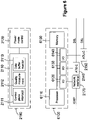
- These means 2180 can be implemented in software or firmware in one or several processor units 6100 as illustrated in Figure 6 .
- This processor unit 6100 comprises a processor 6110, a memory unit 6150 and one or several i/o units 6120, 6130, 6140 that are connected to the network interface 2170 and the ATU-Cs 2140, 2150 respectively.
- the access node 2100 also comprises a Management Information Base MIB 2130 arranged to store power state transitioning parameters which will be described more in detail below.
- MIB 2130 is replaced by an external MIB 2135 that is connected to the access node AN 2100 and that serves as a common information base for a plurality of access nodes.
- the current invention further comprises a method of transitioning from the low transmission power state (L2 state) to the high transmission power state (L0 state).
- Different embodiments of the invention comprise methods to detect selected traffic events that give an "early warning' that a transition is necessary.
- a transition is normally necessary when the bandwidth on the subscriber lines DSL 2201, 2301 is increased.
- a power management request is sent from the ATU-C 2140 in the AN 2100 towards the ATU-R 2211 in the NT 2210.
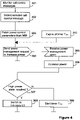
- This request is requesting a decrease of the power cutback (i.e. an increase of transmission power) by requesting a new PCB value lower than the actual value by an amount less or equal to L2_EXPI. If the ATU-R 2211 grants the request, it returns a power management grant to the ATU-C 2140 in step 305.
- step 306 After receiving the power management grant in step 305, the power is increased in step 306, by setting the current power cutback value PCBC to the maximum value of max(PCBC - L2_EXPI, PCB(L0)).
- step 307 the value of PCBC is checked if it equals the value of PCB(L0) (i.e. if the high power state has been reached). If that is not the case, a timer T step is started in step 308 with the value L2_ETXS. When timer T step expires in step 312, steps 304 and 305 are repeated with a new PCB value calculated in the same way as above. If the new value of PCBC equals the value of PCB (L0), a switch to L0 state (i.e. high power state) is performed by the ATU-C 2140 in step 309. In this embodiment, the actual switch to L0 state (step 309) is performed by using the same procedure as disclosed in G.992.3. In addition, the power management request and grant are implemented using L2 power trim messages similar to the power trim messages disclosed in G.992.3.
- adjacent subscriber lines DSL 2301 have time to adapt to the changing noise condition caused by the power increase in conjunction with crosstalk coupling between the copper pairs.
- the transitioning from a low transmission power state to a high transmission power state is triggered by monitoring and detecting a selected traffic event by the traffic event monitor 2110 in the access node AN 2100.
- the current invention also includes a number of embodiments arranged to give an 'early warning' that a transition is necessary.
- the selected traffic event is when the buffer level in the data transmission buffer 2141 in the ATU-C 2140 reaches a certain threshold.
- the data buffer monitor 2112 monitors the buffer level of the data transmission buffer 2141 in step 301. When a predetermined buffer level has been reached in step 302, the transitioning is triggered.
- the threshold must be configured so that a data rate of 64-128 kbits/s is allowed without triggering the transitioning from the L2 state to the L0 state. The rate of 64-128 kbits/s is sufficient for carrying background traffic such as DHCP signaling etc.
- the data buffer monitor 2112 can optionally receive messages from the ATU-R 2211 requesting a transitioning of the power state. These messages can for example be data transmission buffer status messages 2903 that are sent from the ATU-R 2211 when the data transmission buffer 2241 in the ATU-R 2211 reaches a predetermined threshold. These messages can act as traffic events that trigger the transitioning.
- Another option is to extrapolate the buffer fill rate in order to predict when the buffer 2141 in the ATU-C 2140 will become full.
- buffer levels are monitored.
- different buffer levels are defined for different PVCs (Permanent Virtual Channels) and/or for connections with different QoS requirements.
- the QoS requirement can for example be determined by monitoring IEEE 802.1p priority bits in the Ethernet frames or the Differentiated Services Code Point DSCP in the IP packets.
- the traffic event is when a need for bit-swap is detected.
- the transmission quality on the subscriber line DSL 2201 is monitored by the quality measurement unit 2112 in step 310.
- the quality measurement unit 2112 triggers bit-swapping in step 311.
- the trigger to initiate bit-swapping is in the current invention additionally used as a traffic event to trigger the transitioning of the DSL 2201, 2301 from a low to a high transmission power state. Alternatively, the actual bit-swapping is delayed until the transitioning is completed.
- the traffic event is when a selected call control message (i.e. an IGMP message) is received.
- a call control message such as an IGMP Membership Report message coming from a host 161, 162 requesting to join a multicast group is an indication that the data rate will increase and that a transitioning from L2 state to L0 state will become necessary.
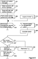
- the call control message intercept unit 2111 in the access node AN 2100 monitors IGMP messages in step 401.
- the intercept unit 2111 detects an IGMP Membership Report message coming from the host 161, 162 requesting to join a multicast group. The detection of this IGMP message triggers the transitioning.
- the intercept unit 2111 delays the retransmit of the IGMP message towards the broadband network 2500 until the transitioning is completed. This is done by keeping in step 501 the IGMP message and retransmitting it in step 502 i.e. not until the transitioning has been completed. By delaying the request to join the multicast group, the risk that the data buffer 2141 will overflow is minimized.
- the remaining steps 303-309, 312, 401-402 in Figure 5 are described in connection with Figures 3 and 4 respectively.
- An alternative (or a complement) to monitor IGMP messages is to monitor other call control messages such as SIP messages related to VoIP Voice over IP sessions.
- a VoIP session using SIP is initiated by sending an INVITE message between a calling and a called party.
- the status that the called party's telephone is ringing is communicated to the calling party by a '180 Ringing' message.
- a '200 OK' message is sent to the calling party.
- the '180 Ringing' message can here be used as the selected traffic event to trigger the transitioning in the same way as described above. As the transitioning normally is completed before the calling party answers, the actual conversation can start in L0 state and the user will not notice any degradation of the VoIP service.
- the power transitioning parameters listed above are dependant on the used service or protocol type (e.g. TCP, UDP, RTSP). Certain services may require quicker transitioning than others. For example, to avoid disturbance on the video stream of an IPTV service, the transitioning could be performed quicker for the IPTV service than for example Internet web-browsing.
- TCP Transmission Control Protocol
- UDP User Datagram Protocol
- RTSP Real-Time Transport Protocol
- Certain services may require quicker transitioning than others. For example, to avoid disturbance on the video stream of an IPTV service, the transitioning could be performed quicker for the IPTV service than for example Internet web-browsing.
- the identity of the PVC or the VLAN (Virtual LAN) carrying the service can be used.
- the transition parameters are dependant on the QoS (Quality of Service) requirements.
- QoS Quality of Service
- the IEEE 802.1p priority bits in the Ethernet frames an/or the Differentiated Services Code Point DSCP in the IP packets are monitored.
- the QoS requirements are fed 2131 into the MIB 2130, 2135 by the traffic event monitor 2110 and different transitioning parameters can be used for connections with different QoS requirements.
- the traffic event monitor 2110 is optionally arranged to combine any of the traffic events described above to a single traffic event that triggers the transitioning.
- the embodiments described above are basically referring to the ADSL technology and ADSL Transceiver Units 2140, 2150, 2211, 2311.
- the inventive concept could very well be used for digital communication lines using other DSL techniques such as VDSL, VDSL2 etc.
Landscapes
- Engineering & Computer Science (AREA)
- Computer Networks & Wireless Communication (AREA)
- Signal Processing (AREA)
- Data Exchanges In Wide-Area Networks (AREA)
- Telephonic Communication Services (AREA)
- Interface Circuits In Exchanges (AREA)
Claims (7)
- Verfahren zum Überführen einer digitalen Kommunikationsleitung (2201), die zwischen einem ersten Kommunikationsknoten (2100) und einem zweiten Kommunikationsknoten (2210) verbunden ist, von einem niedrigen Übertragungsstromzustand in einen hohen Übertragungsstromzustand, folgende Schritte umfassend:- Senden (304) einer Anfrage (2901) von dem ersten Kommunikationsknoten (2100) an den zweiten Kommunikationsknoten (2210), um den Übertragungsstrompegel im ersten Knoten (2100) auf einen neuen Stromwert zu steigern;- Empfangen (305) einer Berechtigung (2902) vom zweiten Knoten (2200);- Steigern (306) des Übertragungsstrompegels auf den neuen Stromwert;- mindestens einmaliges Wiederholen (307) der Schritte des Sendens (304) der Anfrage (2901), des Empfangens (305) der Berechtigung (2902) und des Steigerns (306) des Übertragungsstrompegels, bis der hohe Übertragungsstromzustand erreicht wurde, wobei die Schritte als Reaktion auf das Detektieren eines ausgewählten Datenverkehrsereignisses durch den ersten Kommunikationsknoten durchgeführt werden und wobei das ausgewählte Datenverkehrsereignis- eine Meldung ist, die ein Überführen des durch den zweiten Kommunikationsknoten an den ersten Kommunikationsknoten gesendeten Stromzustandes anfragt, oder- wenn ein Bedarf zur Durchführung eines Bitaustauschs detektiert wird und wobei, wo das ausgewählte Datenverkehrsereignis eine Meldung ist, die ein Überführen des Stromzustandes anfragt, der zweite Kommunikationsknoten ein ATU-R ist und der erste Kommunikationsknoten ein ATU-C ist oder der zweite Kommunikationsknoten ein Äquivalent eines an ATU-R in einer anderen DSL-Technologie als ADSL ist und der erste Kommunikationsknoten ein Äquivalent eines ATU-C in einer andren DSL Technologie als ADSL ist.
- Verfahren nach einem der vorgehenden Ansprüche, ferner umfassend den Schritt:- Abrufen (303) des neuen Stromwerts und eines Werts der Zeit zwischen dem Senden zweier aufeinanderfolgender Anfragen von einer Managementinformationsbasis (2130).
- Verfahren nach Anspruch 2, wobei der neue Stromwert einen Stromdrosselungswert umfasst und wobei die Einheit des Werts in dB gemessen wird.
- Verfahren nach Anspruch 3, wobei die Anfrage (2901) eine Strommanagementkürzungsnachricht und die Berechtigung (2902) eine Strommanagementberechtigungsnachricht ist.
- Erster Kommunikationsknoten (2100), der mit mindestens einem zweiten Kommunikationsknoten (2210) über mindestens eine digitale Kommunikationsleitung (2201) verbindbar ist, wobei der erste Kommunikationsknoten (2100) angeordnet ist, um das Verfahren nach einem der Ansprüche 1 bis 4 durchzuführen.
- Erster Kommunikationsknoten (2100) nach Anspruch 5, der ferner eine Managementinformationsbasis MIB (2130) umfasst, die angeordnet ist, um Stromzustandsüberführungsparameter zu speichern.
- Erster Kommunikationsknoten (2100) nach einem der Ansprüche 5 bis 6, der ferner angeordnet ist, um mit einer externen Managementinformationsbasis MIB (2135) verbindbar zu sein, die angeordnet ist, um Stromzustandsüberführungsparameter zu speichern.
Applications Claiming Priority (3)
| Application Number | Priority Date | Filing Date | Title |
|---|---|---|---|
| US4232708P | 2008-04-04 | 2008-04-04 | |
| PCT/SE2009/050147 WO2009123541A1 (en) | 2008-04-04 | 2009-02-11 | Method and arrangement for the power management of a digital communication line |
| EP09728675.1A EP2258073B1 (de) | 2008-04-04 | 2009-02-11 | Verfahren und anordnung für das strommanagement einer digitalen kommunikationsleitung |
Related Parent Applications (3)
| Application Number | Title | Priority Date | Filing Date |
|---|---|---|---|
| PCT/SE2009/050147 Previously-Filed-Application WO2009123541A1 (en) | 2008-04-04 | 2009-02-11 | Method and arrangement for the power management of a digital communication line |
| EP09728675.1A Division EP2258073B1 (de) | 2008-04-04 | 2009-02-11 | Verfahren und anordnung für das strommanagement einer digitalen kommunikationsleitung |
| EP09728675.1A Division-Into EP2258073B1 (de) | 2008-04-04 | 2009-02-11 | Verfahren und anordnung für das strommanagement einer digitalen kommunikationsleitung |
Publications (2)
| Publication Number | Publication Date |
|---|---|
| EP3301853A1 EP3301853A1 (de) | 2018-04-04 |
| EP3301853B1 true EP3301853B1 (de) | 2022-05-11 |
Family
ID=40533346
Family Applications (2)
| Application Number | Title | Priority Date | Filing Date |
|---|---|---|---|
| EP17169159.5A Active EP3301853B1 (de) | 2008-04-04 | 2009-02-11 | Verfahren und anordnung für das strommanagement einer digitalen kommunikationsleitung |
| EP09728675.1A Active EP2258073B1 (de) | 2008-04-04 | 2009-02-11 | Verfahren und anordnung für das strommanagement einer digitalen kommunikationsleitung |
Family Applications After (1)
| Application Number | Title | Priority Date | Filing Date |
|---|---|---|---|
| EP09728675.1A Active EP2258073B1 (de) | 2008-04-04 | 2009-02-11 | Verfahren und anordnung für das strommanagement einer digitalen kommunikationsleitung |
Country Status (8)
| Country | Link |
|---|---|
| US (2) | US8699363B2 (de) |
| EP (2) | EP3301853B1 (de) |
| CN (1) | CN101978653B (de) |
| AR (1) | AR071358A1 (de) |
| AU (1) | AU2009232475B2 (de) |
| BR (1) | BRPI0909710B1 (de) |
| PL (1) | PL2258073T3 (de) |
| WO (1) | WO2009123541A1 (de) |
Families Citing this family (9)
| Publication number | Priority date | Publication date | Assignee | Title |
|---|---|---|---|---|
| JP5017218B2 (ja) * | 2008-09-12 | 2012-09-05 | アラクサラネットワークス株式会社 | パケット転送装置 |
| EP2369781B1 (de) * | 2010-03-19 | 2012-11-21 | Alcatel Lucent | Garantierte Dienstgüte in Modus mit niedrigem Stromverbrauch |
| US8738824B1 (en) | 2010-04-21 | 2014-05-27 | Marvell International Ltd. | Low power audio codec |
| ES2659522T3 (es) * | 2011-03-10 | 2018-03-16 | Deutsche Telekom Ag | Procedimiento para el funcionamiento de una línea DSL en una red de telecomunicación, equipo de nodo de acceso y equipo de conexión |
| CN103220631B (zh) * | 2012-01-18 | 2016-03-02 | 鼎桥通信技术有限公司 | 集群通信系统、监听终端及其加入方法 |
| EP2648363B1 (de) * | 2012-04-05 | 2017-10-11 | Lantiq Deutschland GmbH | Verfahren zur Regelung eines Leistungsstatus einer Netzwerkeinheit |
| EP3039850B1 (de) * | 2013-08-30 | 2020-05-06 | Adaptive Spectrum and Signal Alignment, Inc. | System und verfahren mit niedrigem stromverbrauch für dsl-leitungen |
| KR20160082687A (ko) * | 2013-11-04 | 2016-07-08 | 이카노스 커뮤니케이션스, 인크. | Xdsl 시스템들의 저전력 모드를 관리하기 위한 방법 및 장치 |
| EP3845008A1 (de) * | 2018-11-12 | 2021-07-07 | Sony Corporation | Verfahren und vorrichtung zur netzwerkverwaltung von hilfsinformationssignalisierung |
Family Cites Families (11)
| Publication number | Priority date | Publication date | Assignee | Title |
|---|---|---|---|---|
| KR100228493B1 (ko) * | 1997-08-30 | 1999-11-01 | 윤종용 | 비대칭 디지털 가입자 라인 시스템에서 송출 전력제어방법 |
| EP0991223A1 (de) | 1998-09-30 | 2000-04-05 | Alcatel | Verfahren und Einrichtung für einen schnellen Übergang eines niedrigen Leistungszustandes zu einem hohen Leistungszustand in ein Kommunikationssystem |
| US6690721B1 (en) * | 2000-01-07 | 2004-02-10 | 3Com Corporation | Method for asymmetric digital subscriber line modem recovery from insufficient transmit power |
| US7406117B2 (en) * | 2002-03-21 | 2008-07-29 | Westell Technologies, Inc. | XDSL multi-hybrid modem with power spectral density shaping |
| EP1643658A1 (de) * | 2004-10-04 | 2006-04-05 | Sony Deutschland GmbH | Netzleitungsübertragungsverfahren |
| CN1832364B (zh) * | 2005-03-10 | 2010-12-01 | 华为技术有限公司 | 提高普通adsl信号传输距离的方法和数字用户线接入复用器 |
| US7668232B2 (en) | 2005-07-08 | 2010-02-23 | Texas Instruments Incorporated | System and method to determine power cutback in communication systems |
| CN101449513B (zh) * | 2006-05-31 | 2012-08-08 | 艾利森电话股份有限公司 | 多播控制 |
| EP2337371B8 (de) * | 2006-06-06 | 2018-05-23 | Assia Spe, Llc | DSL System |
| EP2237470A1 (de) * | 2009-04-03 | 2010-10-06 | Lantiq Deutschland GmbH | Stromsparmodus für DSL-Modems |
| EP2569868B1 (de) * | 2010-05-12 | 2018-12-19 | ADTRAN GmbH | Einstellung einer leistungszuweisung von benutzern in einer digitalen teilnehmerleitungsumgebung |
-
2009
- 2009-02-11 EP EP17169159.5A patent/EP3301853B1/de active Active
- 2009-02-11 PL PL09728675T patent/PL2258073T3/pl unknown
- 2009-02-11 WO PCT/SE2009/050147 patent/WO2009123541A1/en not_active Ceased
- 2009-02-11 CN CN2009801108434A patent/CN101978653B/zh active Active
- 2009-02-11 AU AU2009232475A patent/AU2009232475B2/en active Active
- 2009-02-11 US US12/933,821 patent/US8699363B2/en active Active
- 2009-02-11 EP EP09728675.1A patent/EP2258073B1/de active Active
- 2009-02-11 BR BRPI0909710-4A patent/BRPI0909710B1/pt active IP Right Grant
- 2009-04-03 AR ARP090101208A patent/AR071358A1/es active IP Right Grant
-
2013
- 2013-10-16 US US14/055,504 patent/US9313137B2/en active Active
Also Published As
| Publication number | Publication date |
|---|---|
| CN101978653A (zh) | 2011-02-16 |
| CN101978653B (zh) | 2013-11-06 |
| US20140036684A1 (en) | 2014-02-06 |
| EP2258073A1 (de) | 2010-12-08 |
| EP3301853A1 (de) | 2018-04-04 |
| US8699363B2 (en) | 2014-04-15 |
| US9313137B2 (en) | 2016-04-12 |
| BRPI0909710B1 (pt) | 2020-10-06 |
| BRPI0909710A2 (pt) | 2015-10-06 |
| PL2258073T3 (pl) | 2017-11-30 |
| WO2009123541A1 (en) | 2009-10-08 |
| US20110019578A1 (en) | 2011-01-27 |
| AR071358A1 (es) | 2010-06-16 |
| AU2009232475A1 (en) | 2009-10-08 |
| EP2258073B1 (de) | 2017-06-07 |
| AU2009232475B2 (en) | 2014-04-10 |
Similar Documents
| Publication | Publication Date | Title |
|---|---|---|
| US9313137B2 (en) | Method and arrangement for the power management of a digital communication line | |
| ES2916058T3 (es) | Método y disposición para la gestión de potencia de una línea de comunicación digital | |
| US7937485B2 (en) | Streaming gateway | |
| EP2011324A2 (de) | Netzwerkressourcenoptimierung in einer videokonferenz | |
| CN101233781A (zh) | 运行通过数据网络来传送数据的装置的方法 | |
| WO2008122239A1 (en) | A method, a device and a system for transmitting data | |
| US7444426B2 (en) | Method for selecting a resource to provide a requested service in a multicasting environment | |
| US7173911B1 (en) | System and method for music-on-hold in a voice over internet protocol (VoIP) environment | |
| US8693314B1 (en) | Systems and methods for protecting bonding groups | |
| US7177318B2 (en) | Method and apparatus for managing multicast data on an IP subnet | |
| US20030133437A1 (en) | Digital subscriber line feature for enabling plain old telephone service on digital lines in the event of a power failure | |
| EP3128709B1 (de) | Verfahren zur steuerung eines line-in-zugangsnetzwerks mit darauf angewendeter g.hn-technologie und zugangsnetzwerkleitungskonzentrationsinstrument, zugangsnetzwerkendgerät und zugangsnetzwerksystem damit | |
| EP1983713A1 (de) | Verfahren zum Betreiben eines Netzwerkelements und entsprechende Vorrichtung sowie ein Kommunikationssystem mit einer derartigen Vorrichtung | |
| JP4653851B2 (ja) | 通信関係を確立するための方法と装置 | |
| EP1981218A1 (de) | Verfahren und Vorrichtung zur Einstellung eines Übertragungsmodus und System mit solcher Vorrichtung | |
| US7697568B1 (en) | Method and system for automatic modem bandwidth detection in a router | |
| CN1394040A (zh) | 社区乙太网络交换器的管理系统及其装置 | |
| KR100888919B1 (ko) | 외장형 브이오아이피 단말을 사용한 인터넷전화의 실시간호감시를 통한 서비스 품질 보장 시스템 및 그 방법 | |
| JP2005123688A (ja) | Ip電話用端末装置、ip電話システム、ip電話制御方法、ip電話用プログラム及び管理システム | |
| EP2684348B1 (de) | Verfahren zum betrieb einer dsl-leitung in einem telekommunikationsnetz, zugangsknotengerät und anschlussgerät | |
| CN112383560A (zh) | 一种基于组播和QoS的视频系统 | |
| Zhu et al. | Immediate IPTV channel leave by explicit user tracking in PON | |
| Varbanova et al. | Planning of VoIP System for Hybrid Fiber-Coaxial Television Networks | |
| US20030126269A1 (en) | System and method for automatically configuring a protocol line trace filter | |
| WO2009018681A1 (en) | Apparatus and method for shaping data streaming in an xdsl network |
Legal Events
| Date | Code | Title | Description |
|---|---|---|---|
| PUAI | Public reference made under article 153(3) epc to a published international application that has entered the european phase |
Free format text: ORIGINAL CODE: 0009012 |
|
| STAA | Information on the status of an ep patent application or granted ep patent |
Free format text: STATUS: EXAMINATION IS IN PROGRESS |
|
| 17P | Request for examination filed |
Effective date: 20170503 |
|
| AC | Divisional application: reference to earlier application |
Ref document number: 2258073 Country of ref document: EP Kind code of ref document: P |
|
| AK | Designated contracting states |
Kind code of ref document: A1 Designated state(s): AT BE BG CH CY CZ DE DK EE ES FI FR GB GR HR HU IE IS IT LI LT LU LV MC MK MT NL NO PL PT RO SE SI SK TR |
|
| GRAP | Despatch of communication of intention to grant a patent |
Free format text: ORIGINAL CODE: EPIDOSNIGR1 |
|
| STAA | Information on the status of an ep patent application or granted ep patent |
Free format text: STATUS: GRANT OF PATENT IS INTENDED |
|
| INTG | Intention to grant announced |
Effective date: 20211222 |
|
| GRAS | Grant fee paid |
Free format text: ORIGINAL CODE: EPIDOSNIGR3 |
|
| GRAA | (expected) grant |
Free format text: ORIGINAL CODE: 0009210 |
|
| STAA | Information on the status of an ep patent application or granted ep patent |
Free format text: STATUS: THE PATENT HAS BEEN GRANTED |
|
| AC | Divisional application: reference to earlier application |
Ref document number: 2258073 Country of ref document: EP Kind code of ref document: P |
|
| AK | Designated contracting states |
Kind code of ref document: B1 Designated state(s): AT BE BG CH CY CZ DE DK EE ES FI FR GB GR HR HU IE IS IT LI LT LU LV MC MK MT NL NO PL PT RO SE SI SK TR |
|
| REG | Reference to a national code |
Ref country code: GB Ref legal event code: FG4D |
|
| REG | Reference to a national code |
Ref country code: CH Ref legal event code: EP |
|
| REG | Reference to a national code |
Ref country code: AT Ref legal event code: REF Ref document number: 1492444 Country of ref document: AT Kind code of ref document: T Effective date: 20220515 |
|
| REG | Reference to a national code |
Ref country code: DE Ref legal event code: R096 Ref document number: 602009064443 Country of ref document: DE |
|
| REG | Reference to a national code |
Ref country code: IE Ref legal event code: FG4D |
|
| REG | Reference to a national code |
Ref country code: ES Ref legal event code: FG2A Ref document number: 2916058 Country of ref document: ES Kind code of ref document: T3 Effective date: 20220628 |
|
| REG | Reference to a national code |
Ref country code: LT Ref legal event code: MG9D |
|
| REG | Reference to a national code |
Ref country code: NL Ref legal event code: MP Effective date: 20220511 |
|
| REG | Reference to a national code |
Ref country code: AT Ref legal event code: MK05 Ref document number: 1492444 Country of ref document: AT Kind code of ref document: T Effective date: 20220511 |
|
| PG25 | Lapsed in a contracting state [announced via postgrant information from national office to epo] |
Ref country code: SE Free format text: LAPSE BECAUSE OF FAILURE TO SUBMIT A TRANSLATION OF THE DESCRIPTION OR TO PAY THE FEE WITHIN THE PRESCRIBED TIME-LIMIT Effective date: 20220511 Ref country code: PT Free format text: LAPSE BECAUSE OF FAILURE TO SUBMIT A TRANSLATION OF THE DESCRIPTION OR TO PAY THE FEE WITHIN THE PRESCRIBED TIME-LIMIT Effective date: 20220912 Ref country code: NO Free format text: LAPSE BECAUSE OF FAILURE TO SUBMIT A TRANSLATION OF THE DESCRIPTION OR TO PAY THE FEE WITHIN THE PRESCRIBED TIME-LIMIT Effective date: 20220811 Ref country code: NL Free format text: LAPSE BECAUSE OF FAILURE TO SUBMIT A TRANSLATION OF THE DESCRIPTION OR TO PAY THE FEE WITHIN THE PRESCRIBED TIME-LIMIT Effective date: 20220511 Ref country code: LT Free format text: LAPSE BECAUSE OF FAILURE TO SUBMIT A TRANSLATION OF THE DESCRIPTION OR TO PAY THE FEE WITHIN THE PRESCRIBED TIME-LIMIT Effective date: 20220511 Ref country code: HR Free format text: LAPSE BECAUSE OF FAILURE TO SUBMIT A TRANSLATION OF THE DESCRIPTION OR TO PAY THE FEE WITHIN THE PRESCRIBED TIME-LIMIT Effective date: 20220511 Ref country code: GR Free format text: LAPSE BECAUSE OF FAILURE TO SUBMIT A TRANSLATION OF THE DESCRIPTION OR TO PAY THE FEE WITHIN THE PRESCRIBED TIME-LIMIT Effective date: 20220812 Ref country code: FI Free format text: LAPSE BECAUSE OF FAILURE TO SUBMIT A TRANSLATION OF THE DESCRIPTION OR TO PAY THE FEE WITHIN THE PRESCRIBED TIME-LIMIT Effective date: 20220511 Ref country code: BG Free format text: LAPSE BECAUSE OF FAILURE TO SUBMIT A TRANSLATION OF THE DESCRIPTION OR TO PAY THE FEE WITHIN THE PRESCRIBED TIME-LIMIT Effective date: 20220811 Ref country code: AT Free format text: LAPSE BECAUSE OF FAILURE TO SUBMIT A TRANSLATION OF THE DESCRIPTION OR TO PAY THE FEE WITHIN THE PRESCRIBED TIME-LIMIT Effective date: 20220511 |
|
| PG25 | Lapsed in a contracting state [announced via postgrant information from national office to epo] |
Ref country code: PL Free format text: LAPSE BECAUSE OF FAILURE TO SUBMIT A TRANSLATION OF THE DESCRIPTION OR TO PAY THE FEE WITHIN THE PRESCRIBED TIME-LIMIT Effective date: 20220511 Ref country code: LV Free format text: LAPSE BECAUSE OF FAILURE TO SUBMIT A TRANSLATION OF THE DESCRIPTION OR TO PAY THE FEE WITHIN THE PRESCRIBED TIME-LIMIT Effective date: 20220511 Ref country code: IS Free format text: LAPSE BECAUSE OF FAILURE TO SUBMIT A TRANSLATION OF THE DESCRIPTION OR TO PAY THE FEE WITHIN THE PRESCRIBED TIME-LIMIT Effective date: 20220911 |
|
| PG25 | Lapsed in a contracting state [announced via postgrant information from national office to epo] |
Ref country code: SK Free format text: LAPSE BECAUSE OF FAILURE TO SUBMIT A TRANSLATION OF THE DESCRIPTION OR TO PAY THE FEE WITHIN THE PRESCRIBED TIME-LIMIT Effective date: 20220511 Ref country code: RO Free format text: LAPSE BECAUSE OF FAILURE TO SUBMIT A TRANSLATION OF THE DESCRIPTION OR TO PAY THE FEE WITHIN THE PRESCRIBED TIME-LIMIT Effective date: 20220511 Ref country code: EE Free format text: LAPSE BECAUSE OF FAILURE TO SUBMIT A TRANSLATION OF THE DESCRIPTION OR TO PAY THE FEE WITHIN THE PRESCRIBED TIME-LIMIT Effective date: 20220511 Ref country code: DK Free format text: LAPSE BECAUSE OF FAILURE TO SUBMIT A TRANSLATION OF THE DESCRIPTION OR TO PAY THE FEE WITHIN THE PRESCRIBED TIME-LIMIT Effective date: 20220511 Ref country code: CZ Free format text: LAPSE BECAUSE OF FAILURE TO SUBMIT A TRANSLATION OF THE DESCRIPTION OR TO PAY THE FEE WITHIN THE PRESCRIBED TIME-LIMIT Effective date: 20220511 |
|
| REG | Reference to a national code |
Ref country code: DE Ref legal event code: R097 Ref document number: 602009064443 Country of ref document: DE |
|
| PLBE | No opposition filed within time limit |
Free format text: ORIGINAL CODE: 0009261 |
|
| STAA | Information on the status of an ep patent application or granted ep patent |
Free format text: STATUS: NO OPPOSITION FILED WITHIN TIME LIMIT |
|
| 26N | No opposition filed |
Effective date: 20230214 |
|
| PG25 | Lapsed in a contracting state [announced via postgrant information from national office to epo] |
Ref country code: SI Free format text: LAPSE BECAUSE OF FAILURE TO SUBMIT A TRANSLATION OF THE DESCRIPTION OR TO PAY THE FEE WITHIN THE PRESCRIBED TIME-LIMIT Effective date: 20220511 |
|
| REG | Reference to a national code |
Ref country code: DE Ref legal event code: R119 Ref document number: 602009064443 Country of ref document: DE |
|
| PG25 | Lapsed in a contracting state [announced via postgrant information from national office to epo] |
Ref country code: MC Free format text: LAPSE BECAUSE OF FAILURE TO SUBMIT A TRANSLATION OF THE DESCRIPTION OR TO PAY THE FEE WITHIN THE PRESCRIBED TIME-LIMIT Effective date: 20220511 |
|
| REG | Reference to a national code |
Ref country code: CH Ref legal event code: PL |
|
| REG | Reference to a national code |
Ref country code: BE Ref legal event code: MM Effective date: 20230228 |
|
| GBPC | Gb: european patent ceased through non-payment of renewal fee |
Effective date: 20230211 |
|
| PG25 | Lapsed in a contracting state [announced via postgrant information from national office to epo] |
Ref country code: LU Free format text: LAPSE BECAUSE OF NON-PAYMENT OF DUE FEES Effective date: 20230211 Ref country code: LI Free format text: LAPSE BECAUSE OF NON-PAYMENT OF DUE FEES Effective date: 20230228 Ref country code: CH Free format text: LAPSE BECAUSE OF NON-PAYMENT OF DUE FEES Effective date: 20230228 |
|
| REG | Reference to a national code |
Ref country code: IE Ref legal event code: MM4A |
|
| PG25 | Lapsed in a contracting state [announced via postgrant information from national office to epo] |
Ref country code: GB Free format text: LAPSE BECAUSE OF NON-PAYMENT OF DUE FEES Effective date: 20230211 |
|
| PG25 | Lapsed in a contracting state [announced via postgrant information from national office to epo] |
Ref country code: IE Free format text: LAPSE BECAUSE OF NON-PAYMENT OF DUE FEES Effective date: 20230211 Ref country code: GB Free format text: LAPSE BECAUSE OF NON-PAYMENT OF DUE FEES Effective date: 20230211 Ref country code: FR Free format text: LAPSE BECAUSE OF NON-PAYMENT OF DUE FEES Effective date: 20230228 Ref country code: DE Free format text: LAPSE BECAUSE OF NON-PAYMENT OF DUE FEES Effective date: 20230901 |
|
| PG25 | Lapsed in a contracting state [announced via postgrant information from national office to epo] |
Ref country code: BE Free format text: LAPSE BECAUSE OF NON-PAYMENT OF DUE FEES Effective date: 20230228 |
|
| PGFP | Annual fee paid to national office [announced via postgrant information from national office to epo] |
Ref country code: TR Payment date: 20240130 Year of fee payment: 16 |
|
| PG25 | Lapsed in a contracting state [announced via postgrant information from national office to epo] |
Ref country code: BG Free format text: LAPSE BECAUSE OF FAILURE TO SUBMIT A TRANSLATION OF THE DESCRIPTION OR TO PAY THE FEE WITHIN THE PRESCRIBED TIME-LIMIT Effective date: 20220511 |
|
| PG25 | Lapsed in a contracting state [announced via postgrant information from national office to epo] |
Ref country code: BG Free format text: LAPSE BECAUSE OF FAILURE TO SUBMIT A TRANSLATION OF THE DESCRIPTION OR TO PAY THE FEE WITHIN THE PRESCRIBED TIME-LIMIT Effective date: 20220511 |
|
| PG25 | Lapsed in a contracting state [announced via postgrant information from national office to epo] |
Ref country code: CY Free format text: LAPSE BECAUSE OF FAILURE TO SUBMIT A TRANSLATION OF THE DESCRIPTION OR TO PAY THE FEE WITHIN THE PRESCRIBED TIME-LIMIT; INVALID AB INITIO Effective date: 20090211 |
|
| PG25 | Lapsed in a contracting state [announced via postgrant information from national office to epo] |
Ref country code: HU Free format text: LAPSE BECAUSE OF FAILURE TO SUBMIT A TRANSLATION OF THE DESCRIPTION OR TO PAY THE FEE WITHIN THE PRESCRIBED TIME-LIMIT; INVALID AB INITIO Effective date: 20090211 |
|
| PGFP | Annual fee paid to national office [announced via postgrant information from national office to epo] |
Ref country code: ES Payment date: 20260302 Year of fee payment: 18 |
|
| PGFP | Annual fee paid to national office [announced via postgrant information from national office to epo] |
Ref country code: IT Payment date: 20260219 Year of fee payment: 18 |
|
| PG25 | Lapsed in a contracting state [announced via postgrant information from national office to epo] |
Ref country code: TR Free format text: LAPSE BECAUSE OF NON-PAYMENT OF DUE FEES Effective date: 20250211 |