EP2569868B1 - Einstellung einer leistungszuweisung von benutzern in einer digitalen teilnehmerleitungsumgebung - Google Patents
Einstellung einer leistungszuweisung von benutzern in einer digitalen teilnehmerleitungsumgebung Download PDFInfo
- Publication number
- EP2569868B1 EP2569868B1 EP10720583.3A EP10720583A EP2569868B1 EP 2569868 B1 EP2569868 B1 EP 2569868B1 EP 10720583 A EP10720583 A EP 10720583A EP 2569868 B1 EP2569868 B1 EP 2569868B1
- Authority
- EP
- European Patent Office
- Prior art keywords
- new
- power allocation
- user
- users
- determined
- Prior art date
- Legal status (The legal status is an assumption and is not a legal conclusion. Google has not performed a legal analysis and makes no representation as to the accuracy of the status listed.)
- Active
Links
Images


Classifications
-
- H—ELECTRICITY
- H04—ELECTRIC COMMUNICATION TECHNIQUE
- H04B—TRANSMISSION
- H04B3/00—Line transmission systems
- H04B3/02—Details
- H04B3/32—Reducing cross-talk, e.g. by compensating
-
- H—ELECTRICITY
- H04—ELECTRIC COMMUNICATION TECHNIQUE
- H04B—TRANSMISSION
- H04B3/00—Line transmission systems
- H04B3/02—Details
- H04B3/46—Monitoring; Testing
- H04B3/487—Testing crosstalk effects
-
- H—ELECTRICITY
- H04—ELECTRIC COMMUNICATION TECHNIQUE
- H04L—TRANSMISSION OF DIGITAL INFORMATION, e.g. TELEGRAPHIC COMMUNICATION
- H04L5/00—Arrangements affording multiple use of the transmission path
-
- H—ELECTRICITY
- H04—ELECTRIC COMMUNICATION TECHNIQUE
- H04L—TRANSMISSION OF DIGITAL INFORMATION, e.g. TELEGRAPHIC COMMUNICATION
- H04L5/00—Arrangements affording multiple use of the transmission path
- H04L5/0001—Arrangements for dividing the transmission path
- H04L5/0003—Two-dimensional division
- H04L5/0005—Time-frequency
- H04L5/0007—Time-frequency the frequencies being orthogonal, e.g. OFDM(A) or DMT
-
- H—ELECTRICITY
- H04—ELECTRIC COMMUNICATION TECHNIQUE
- H04L—TRANSMISSION OF DIGITAL INFORMATION, e.g. TELEGRAPHIC COMMUNICATION
- H04L5/00—Arrangements affording multiple use of the transmission path
- H04L5/003—Arrangements for allocating sub-channels of the transmission path
- H04L5/0037—Inter-user or inter-terminal allocation
Definitions
- the invention relates to a method and to a device for adjusting a power allocation of users in a digital subscriber line environment.
- a system comprising at least one such device is suggested.
- DSL or xDSL is a family of technologies that provide digital data transmission in particular over wires of a local telephone network.
- High speed Internet access is gaining importance and can be via xDSL services using existing copper lines.
- other applications emerge that require broadband transmission services, e.g., triple play offers comprising subscriber access to Internet, TV and voice data transmission.
- a bandwidth consuming application is the transmission of TV data via xDSL, wherein one HDTV channel may require a data rate amounting to 12 Mbit/s.
- crosstalk noise limits the performance.
- crosstalk noise may vary over time: There may be low crosstalk noise when a significant amount of customers have switched off their equipment and there may be a considerable amount of crosstalk noise during business hours when the majority of customers use their devices.
- Fig.1 shows a schematic diagram of a cable or binder 101 comprising several lines 102, 103 of a DSL system.
- the lines 102 and 103 are connected at one side to a DSLAM 104 that could be deployed at a central office or at a remote terminal and on the other side the line 102 is connected to a CPE 105 and the line 103 is connected to a CPE 106.
- Crosstalk occurs between the lines 102 and 103 that are coupled by the binder 101:
- the crosstalk comprises a near-end crosstalk (NEXT) 107 and 108 as well as far-end crosstalk (FEXT) 109 and 110.
- NXT near-end crosstalk
- FXT far-end crosstalk
- Such crosstalk is perceived at a receiver of a victim (coupled) line as noise and therefore decreases a signal-to-noise ratio (SNR) at this receiver thereby reducing an attainable data rate on this line.
- SNR signal-to-noise ratio
- the twisted pair communication channel is frequency selective, i.e. the direct channel attenuates higher frequencies more than lower frequencies, but the electromagnetic coupling between twisted pair lines provides higher crosstalk with increasing frequency.
- DMT Discrete Multi-Tone
- DSM Dynamic Spectrum Management
- Level 2 is an approach to improve an overall system performance by centrally shaping transmit spectra (which corresponds to shaping of power allocations) of interfering lines so that a performance loss due to crosstalk effects is minimized.
- SMC Spectrum Management Center
- SMC Spectrum Management Center
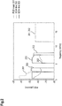
- Fig.2 shows a schematic diagram of an optimal downstream power allocation for a VDSL2 system with two users (with different loop lengths amounting to 300m for the first user and to 600m for the second user) determined by a SMC using DSM.
- user in this regard may in particular refer to a CPE or a terminal.
- the user may in particular be a DSL modem.
- Fig.2 comprises a power spectrum density (PSD) mask 201 which can be utilized by both users, wherein a PSD allocation of the first user (the 300m user) is indicated by a graph 202 and a PSD allocation of the second user (the 600m user) is indicated by a graph 203.
- PSD power spectrum density
- the SMC assigns the frequency band above ca. 8 MHz exclusively to the 300m user (see graph 202), because the 600m user (see graph 203) cannot efficiently transmit data at this range due to high direct channel attenuation. In a range below 8 MHz, the SMC instructs the 300m user (see graph 202) to reduce its transmit power in order to limit its interference with the 600m user.
- the power allocation provided by the SMC may provide a target SNR margin, which protects the users of the DSM system from (arbitrary or not expected) noise fluctuations, e.g., crosstalk from legacy systems or other interferers.
- a target margin of, e.g., 6 dB can be provided to ensure a specified service quality, i.e. bit-error-ratio (BER) and data rate.
- BER bit-error-ratio
- the actual noise may increase by up to 6 dB relative to the noise level that has been assumed by the SMC when computing the power allocations.
- DSM Level 2 tries to mitigate the capacity loss due to crosstalk by centrally coordinating the modem's transmit power allocation, effectively introducing politeness between users.
- Existing solutions are not able to cope with a scenario that some optimal joint power allocation computed by an SMC according to current channel conditions may become invalid at some point in the future when the channel or DSM system parameters change, e.g.,
- the SMC has to determine a new joint allocation that corresponds to the new situation.
- transmit spectra of modems that are already active cannot be reconfigured without interrupting their service, which in most cases is inacceptable and should therefore be avoided. Instead, updating the transmit power profile is thus delayed until a modem enters a (re-)initialization phase.
- said minimum SNR margin can be provided for all active users of the digital subscriber line environment, i.e. for all users that are in show-time.
- the PSD of the at least one user that joins the digital subscriber line environment is adjusted such that it converges towards the new power allocation and that it does not interfere with already active users in a way that their SNR drops below said minimum SNR margin.
- the intermediate power allocations (of the transition phase towards the new power allocation) can be determined such that an SNR margin for all users does not fall below said predefined minimum SNR margin.
- a transition is provided that allows the DSL environment to gradually adjust to and eventually reach the new power allocation without a significant impairment to existing users.
- the solution provided allows to gradually update power allocations in a DSM system and assures that at each point during such gradual transition, an actual SNR margin for each user does not fall below a given minimum value.
- At least one intermediate power allocation is determined that converges towards the new power allocation.
- an(other) intermediate power allocation stage can be determined.
- the approach can be iteratively applied to converge via several intermediate power allocations toward the new (target) power allocation.
- initializing refers to a user that wants to get connected (or re-connected) to the DSL environment.
- the updating scheme suggested advantageously updates or adjusts the power allocation if a user (re-)initializes a new session.
- the digital subscriber line environment comprises at least one DSM system, which is managed by an SMC.
- the SMC may be a centralized component that provides the adjustment of power allocations. Also the SMC may be realized as at least one physical entity or it may be combined with an existing physical entity.
- the predefined minimum SNR margin can be provided for the intermediate power allocation or individually for each user for which the intermediate power allocation is determined or for every subcarrier or a portion of users or subcarriers.
- the intermediate power allocation is determined utilizing spectral limitation masks as well as a limited power budget per the at least one user, which limited power budget is in particular distributed among tones of a DMT modulation scheme.
- the intermediate power allocation is determined such that a distance metric between an actual power allocation and the new power allocation is reduced, in particular minimized.
- the distance metric is reduced meeting at least one of the following constraints:
- the distance metric according to ⁇ ( s ( i ), s new ) comprises at least one of the properties:
- s k , new n can be set to a small positive value.
- the intermediate power allocation is determined by solving the following optimization problem: s . t . R n ⁇ ⁇
- n ⁇ ⁇ is a user; determines a group comprising the at least one user initializing with the digital subscriber line environment; determines the users sharing the same binder; s k n denotes a PSD of the transmit signal of a user n ; s k , mask n is a PSD mask determined by a band profile used; k determines a subchannel or tone; s new is the new power allocation; s ( i ) is the intermediate power allocation at a step i ; ⁇ is the predetermined minimum SNR margin; R n is a data rate of the user
- the optimization problem is solved by a dual decomposition combined with a convex relaxation.
- a dual problem s . t . ⁇ n , ⁇ n ⁇ 0 ⁇ n 0 ⁇ s k n i ⁇ s k , mask n ⁇ n , k of the optimization problem is solved by solving K independent sub-problems s . t . 0 ⁇ s k n i ⁇ s k , mask n ⁇ n per Lagrange multiplier search step.
- a low intermediate minimum SNR margin ⁇ increases the flexibility of shaping the power allocations and thus tends to reduce the number of required intermediate steps i before all users reach the value of the new (target) power allocation s new .
- a trade-off decision can be made between a faster convergence and a reduced protection against fluctuation of noise.
- a device comprising or being associated with a processing unit that is arranged such that the method as described herein is executable thereon.
- processing unit can comprise at least one, in particular several means that are arranged to execute the steps of the method described herein.
- the means may be logically or physically separated; in particular several logically separate means could be combined in at least one physical unit.
- Said processing unit may comprise at least one of the following: a processor, a microcontroller, a hard-wired circuit, an ASIC, an FPGA, a logic device.
- the device is a modem, a DSLAM or a centralized network component, in particular a spectrum management center.
- the solution provided herein further comprises a computer program product directly loadable into a memory of a digital computer, comprising software code portions for performing the steps of the method as described herein.
- a computer-readable medium e.g., storage of any kind, having computer-executable instructions adapted to cause a computer system to perform the method as described herein.
- a communication system comprising at least one device as described herein.
- the solution provided herewith suggests determining intermediate power allocations for users initializing a new session and to provide a favorable transition phase so that the xDSL system can eventually reach a new (target) multi-user power allocation that may be determined by an SMC.
- the power allocation is also referred to as a (transmit) spectrum.
- a user referred to herein may also be regarded as terminal, CPE or modem (or vice versa).
- the intermediate power allocations (of the transition phase towards the new power allocation) can be determined such that an SNR margin for all users does not fall below a predefined threshold.
- the updating scheme suggested in particular updates or adjusts the power allocation if a user (modem) initializes a new session.
- modem initializes a new session.
- the intermediate power allocations can be determined utilizing spectral limitation masks as well as a limited power budget per modem, which is distributed among tones of a DMT modulation scheme.
- a (further) intermediate power allocation for this at least one user is determined such that a distance metric between the intermediate (multi-user) power allocation and the new power allocation s new is reduced, in particular minimized and at least one of the following constraints can be met:
- the minimum SNR margin ⁇ may be chosen individually for every optimization stage, for every subcarrier (or a portion thereof) and/or individually for each user whose transmit spectrum is to be (re-)computed.
- Fig.4 shows a (downstream) multi-user power allocation at an initial state, also referred to as power allocation s old for a DSM system comprising three VDSL users with loop lengths of X meters, wherein X amounts to 400, 800 and 1000.
- the respective user is also referred to as the X m user.
- Fig.4 depicts a PSD mask 405 and power allocations for the 400m user 401, the 800m user 403 and the 1000m user 404.
- a new user also referred to as 600m user 402 (because of its loop length amounting to 600m) joins the DSM system and starts a new session so that the SMC has to re-calculate the power allocation, i.e. determine the new optimized allocation s new for the 4-user system.
- Such new power allocation s new is shown in Fig.5 . It is noted that both power allocations s old and s new provide a target SNR margin amounting to 6dB.
- the spectrum allocated for the 600m user 402 for this intermediate power allocation s ( i ) is selected to converge towards the new power allocation s new ; the other users (which are in show-time according to this example) maintain operation with their previously set configurations.
- a channel model for a static DSL system comprises a set of users sharing the same binder, thus causing mutual FEXT on each other's lines.
- the interference channel is divided into K independent subchannels k .
- the direct channel of user n ⁇ on tone k can be described by a single complex coefficient h k n , n .
- a crosstalk channel from a disturber m to a victim line n on the tone k can be given by a complex scalar h k n , m ( m ⁇ n ).
- s k n denotes a PSD of the transmit signal of a user n
- ⁇ k 2 denotes a combined PSD of alien FEXT and receiver background noise on the tone k .
- 2 are the crosstalk and direct channel gain coefficients.
- the optimal joint power allocation is determined using a spectrum balancing algorithm which typically accounts for at least three per-user constraints in the optimization process:
- s new s k , new n
- n ⁇ N ; k 1, ... , K is required, which is optimized for a time t ⁇ t 0 , but cannot be applied for those users that are already in show-time without interrupting their service.
- s i s k n i
- s k n i s k n i ⁇ 1 ⁇ k .
- the DSM system is fully updated and has reached its new power allocation s new .
- an actual SNR margin ⁇ n ( i ) of the user n resulting from a given multi-user power allocation s ( i ) can be obtained by solving the equation R n ⁇ n i
- s i ⁇ R target n 0
- a distance metric according to ⁇ ( s ( i ), s new ) may comprise at least one of the properties:
- new n can be lower-bounded to some sufficiently small positive value s min .
- s min a value of -130 dBm/Hz could be useful for DSL applications.
- the intermediate power allocation s ( i ) is obtained by solving the following optimization problem
- a convergence analysis of the proposed scheme could be summarized as follows: Basically, a sequence of optimized power allocations ⁇ ( s ( i ), s new ) ⁇ is monotonously decreasing, i.e. ⁇ s i , s new ⁇ ⁇ s i ⁇ 1 , s new .
- DSL sessions are of limited (finite) duration and for every instance i with s ⁇ s new , there will always be a succeeding instance j > i such that ⁇ s j , s new ⁇ ⁇ s i , s new , which implies convergence of the system to finally reach the new power allocation s new within a finite number of (time) steps.
- An existence of a feasible intermediate power allocation s(i) can be shown by the following induction: If a feasible solution for the intermediate power allocation s ( i ) exists, this solution will also be feasible for a succeeding intermediate power allocation s ( i + 1). The remaining issue is to find an initial power allocation s (0) that also is feasible.
- a low intermediate margin ⁇ increases the flexibility of shaping the spectra and thus tends to reduce the number of required intermediate steps i before all users can be set to the new (target) power allocation s new .
- a trade-off decision can be made between a faster convergence and a reduced protection against fluctuation of noise.
- Equation (14) exposes a d.c. structure and can thus be solved using the approach as described in [ P. Tsiaflakis, J. Vangorp, M. Moonen and J. Verlinden: Convex Relaxation Based Low-Complexity Optimal Spectrum Balancing for Multi-User DSL. In Acoustics, Speech and Signal Processing, 2007, ICASSP 2007. IEEE International Conference, volume 3, pages II-349 to III-352, April 2007 ].
- the approach presented guarantees a minimum SNR margin for each user during each (intermediate) stage of an iterative optimization of the power allocation towards a target value s new .
- the service stability can be significantly improved as the DSM system can be well protected against fluctuations of noise that is not managed by the DSM system (i.e. the SMC).
- forced re-configuration or re-training of users that are already in show-time and hence service interruptions can be largely avoided.
Landscapes
- Engineering & Computer Science (AREA)
- Signal Processing (AREA)
- Computer Networks & Wireless Communication (AREA)
- Telephonic Communication Services (AREA)
Claims (15)
- Verfahren zum Anpassen einer Leistungszuteilung von Nutzern in einer digitalen Teilnehmeranschlussleitungsumgebung,- wobei eine Zwischen-Leistungszuteilung bestimmt wird für mindestens einen mit der digitalen Teilnehmeranschlussleitungsumgebung initialisierenden Nutzer auf Grundlage einer neuen Leistungszuteilung, die für die diesen mindestens einen Nutzer aufweisende digitale Teilnehmeranschlussleitungsumgebung bestimmt wird;- wobei die Zwischen-Leistungszuteilung eine vordefinierte minimale SNR-Reserve für die aktiven Nutzer der digitalen Teilnehmeranschlussleitungsumgebung bereitstellt;- wobei mindestens eine Zwischen-Leistungszuteilung bestimmt wird, die auf die neue Leistungszuteilung konvergiert.
- Verfahren nach einem der vorhergehenden Ansprüche, wobei die digitale Teilnehmeranschlussleitungsumgebung mindestens ein DSM-System umfasst, das von einem SMC gemanagt wird.
- Verfahren nach einem der vorhergehenden Ansprüche, wobei die vordefinierte minimale SNR-Reserve für die Zwischen-Leistungszuteilung bereitgestellt werden kann oder individuell für jeden Nutzer, für welchen die Zwischen-Leistungszuteilung bestimmt wird oder für jeden Subträger oder einen Anteil von Nutzern oder Subträgern.
- Verfahren nach einem der vorhergehenden Ansprüche, wobei die Zwischen-Leistungszuteilung bestimmt wird unter Verwendung von Spektralbegrenzungsmasken sowie einem begrenzten Leistungsbudget pro dem mindestens einen Nutzer, wobei das begrenzte Leistungsbudget insbesondere unter Tönen eines DMT-Modulationsschemas verteilt ist.
- Verfahren nach einem der vorhergehenden Ansprüche, wobei die Zwischen-Leistungszuteilung derart bestimmt wird, dass ein Entfernungsmaß zwischen einer derzeitigen Leistungszuteilung und der neuen Leistungszuteilung verringert, insbesondere minimiert, wird.
- Verfahren nach Anspruch 5, wobei das Entfernungsmaß verringert ist, wenn mindestens eine der folgenden Zwangsbedingungen erfüllt ist:- eine Gesamtsendeleistung ist beschränkt;- eine Sendeleistung auf jedem Subträger oder Ton wird individuell durch eine Leistungsspektrumsdichtemaske beschränkt;- für die minimale SNR-Reserve ist eine von jedem Nutzer mit der erhaltenen Leistungszuteilung erreichte Datenrate gleich einer vorbestimmten Zieldatenrate oder übersteigt diese.
- Verfahren nach einem der Ansprüche 5 oder 6, wobei das Entfernungsmaß gemäß Δ(s(i), snew ) mindestens eine der folgenden Eigenschaften aufweist:- Δ ist konvex in
 - Δ ist separierbar in
 - Δ(s(i), snew ) weist ein eindeutiges globales Minimum für s(i) = s new auf.
 - Verfahren nach einem der Ansprüche 5 bis 7, wobei das Entfernungsmaß eine Entfernungsfunktion wie folgt umfasst:


 k einen Subkanal oder Ton bestimmt;snew die neue Leistungszuteilung ist;s(i) die Zwischen-Leistungszuteilung in einem Schritt i ist.
 - Verfahren nach einem der vorhergehenden Ansprüche, wobei die Zwischen-Leistungszuteilung bestimmt wird durch Lösen des folgenden Optimierungsproblems:


 n ∈⊆
n ∈⊆ ein Nutzer ist;
 eine Gruppe bestimmt, die den mindestens einen mit der digitalen Teilnehmeranschlussleitungsumgebung initialisierenden Nutzer aufweist;
 die Nutzer bestimmt, die sich denselben Binder teilen;

 k einen Subkanal oder Ton bestimmt;snew die neue Leistungszuteilung ist;s(i) die Zwischen-Leistungszuteilung in einem Schritt i ist;
γ die vordefinierte minimale SNR-Reserve ist;Rn eine Datenrate des Nutzers n ist;

- Verfahren nach Anspruch 9, wobei das Optimierungsproblem durch eine Dualzerlegung in Kombination mit einer konvexen Relaxation gelöst wird.
- Verfahren nach Anspruch 10, wobei das Optimierungsproblem gelöst wird durch Zerlegen einer Lagrange-Funktion
 ωn eine duale Variable ist, die der Datenratenzwangsbedingung von Nutzer n entspricht; undλ n eine duale Variable ist, die der Leistungszwangsbedingung entspricht,in Lagrange-Funktionen Λ k pro Ton gemäß

- Verfahren nach Anspruch 11, wobei ein duales Problem




- Verfahren nach einem der Ansprüche 9 bis 12,- wobei bei einem Anfangsschritt i = 0 bestimmt wird, ob die minimale SNR-Reserve
γ mit 1 ≤γ ≤ γtarget existiert, so dass das Optimierungsproblem für s(0) machbar ist;- wobei im Falle, dass solch eine minimale SNR-Reserveγ existiert, dieser Wert verwendet wird zum Bestimmen der mindestens einen Zwischen-Leistungszuteilung;- wobei im Falle, dass keine solche minimale SNR-Reserveγ ≥ 1 existiert, die Mengeum mindestens einen zusätzlichen Nutzer erweitert wird, dessen Leistungszuteilung zu dem Zeitpunkt t = t 0 neu zugeschnitten wird.
- Vorrichtung, umfassend eine Verarbeitungseinheit, die derart eingerichtet ist, dass das Verfahren nach Anspruch 1 darauf ausführbar ist.
- Vorrichtung nach Anspruch 14, wobei die Vorrichtung ein Modem, ein DSLAM oder eine zentralisierte Netzkomponente, insbesondere ein Spektrummanagementzentrum, ist.
Applications Claiming Priority (1)
| Application Number | Priority Date | Filing Date | Title |
|---|---|---|---|
| PCT/EP2010/056577 WO2011141064A1 (en) | 2010-05-12 | 2010-05-12 | Adjusting a power allocation of users in a digital subscriber line environment |
Publications (2)
| Publication Number | Publication Date |
|---|---|
| EP2569868A1 EP2569868A1 (de) | 2013-03-20 |
| EP2569868B1 true EP2569868B1 (de) | 2018-12-19 |
Family
ID=43216770
Family Applications (1)
| Application Number | Title | Priority Date | Filing Date |
|---|---|---|---|
| EP10720583.3A Active EP2569868B1 (de) | 2010-05-12 | 2010-05-12 | Einstellung einer leistungszuweisung von benutzern in einer digitalen teilnehmerleitungsumgebung |
Country Status (3)
| Country | Link |
|---|---|
| US (2) | US8867712B2 (de) |
| EP (1) | EP2569868B1 (de) |
| WO (1) | WO2011141064A1 (de) |
Families Citing this family (4)
| Publication number | Priority date | Publication date | Assignee | Title |
|---|---|---|---|---|
| EP2258073B1 (de) | 2008-04-04 | 2017-06-07 | Telefonaktiebolaget LM Ericsson (publ) | Verfahren und anordnung für das strommanagement einer digitalen kommunikationsleitung |
| US9787333B2 (en) | 2013-09-13 | 2017-10-10 | Hewlett Packard Enterprise Development Lp | Subcarrier power reallocation |
| GB2561010A (en) * | 2017-03-31 | 2018-10-03 | British Telecomm | Method and apparatus for transmitting signals over wire connections |
| CN111224764A (zh) * | 2019-11-22 | 2020-06-02 | 国网河南省电力公司电力科学研究院 | 一种基于子载波功率分配方案的物理层安全算法 |
Family Cites Families (3)
| Publication number | Priority date | Publication date | Assignee | Title |
|---|---|---|---|---|
| US7158563B2 (en) | 2001-06-01 | 2007-01-02 | The Board Of Trustees Of The Leland Stanford Junior University | Dynamic digital communication system control |
| US8498408B2 (en) * | 2009-06-29 | 2013-07-30 | Alcatel Lucent | Crosstalk estimation and power setting based on interpolation in a multi-channel communication system |
| US9106735B2 (en) * | 2009-11-25 | 2015-08-11 | Adaptive Spectrum And Signal Alignment, Inc. | Detection of wiring defects |
-
2010
- 2010-05-12 WO PCT/EP2010/056577 patent/WO2011141064A1/en not_active Ceased
- 2010-05-12 EP EP10720583.3A patent/EP2569868B1/de active Active
- 2010-05-12 US US13/697,644 patent/US8867712B2/en active Active
-
2014
- 2014-09-16 US US14/487,675 patent/US20150003597A1/en not_active Abandoned
Non-Patent Citations (1)
| Title |
|---|
| None * |
Also Published As
| Publication number | Publication date |
|---|---|
| WO2011141064A1 (en) | 2011-11-17 |
| US8867712B2 (en) | 2014-10-21 |
| US20130208876A1 (en) | 2013-08-15 |
| EP2569868A1 (de) | 2013-03-20 |
| US20150003597A1 (en) | 2015-01-01 |
Similar Documents
| Publication | Publication Date | Title |
|---|---|---|
| EP1863249B1 (de) | Verfahren und Vorrichtung zur dynamischen Spektrumsverwaltung einer vom Aufwärts- und Abwärtsstrom gemeinsam benutzten xDSL-Frequenz | |
| EP2088686B1 (de) | Verfahren und einrichtung zur verwaltung des frequenzspektrums | |
| EP2259456B1 (de) | Dynamische Digital-Kommunikationssystemsteuerung | |
| CN103004099B (zh) | 一种降低数字用户线路干扰的方法、装置和系统 | |
| US20110206101A1 (en) | Technique for noise mitigation in xdsl lines | |
| US10819498B2 (en) | Method and apparatus for transmitting signals over a wire connection | |
| EP1583308B1 (de) | Verteilte Leistungsspektrumsteuerung für DSL Kommunikationen | |
| US20150003597A1 (en) | Method and device for adjusting a power allocation of users in a digital subscriber line environment | |
| US8199631B2 (en) | Method and device for processing a channel and communication system comprising such device | |
| Tsiaflakis et al. | An efficient search algorithm for the Lagrange multipliers of optimal spectrum balancing in multi-user xDSL systems | |
| EP3373456B1 (de) | Verfahren und anordnung in einem system mit digitaler teilnehmerleitung (dsl) | |
| US20180041246A1 (en) | Line grouping for crosstalk avoidance | |
| EP2146473B1 (de) | Verfahren und Vorrichtung zur Datenverarbeitung und Kommunikationssystem mit einer derartigen Vorrichtung | |
| Tsiaflakis et al. | An efficient Lagrange Multiplier search algorithm for Optimal Spectrum Balancing in crosstalk dominated xDSL systems | |
| US8917863B2 (en) | Method and device for data processing in a digital subscriber line environment | |
| Würtz et al. | Seamless transition of power allocation in multi-user XDSL systems | |
| Sharma et al. | A low complexity based spectrum management algorithm for ‘Near–Far’problem in VDSL environment | |
| Vangorp et al. | Joint spectrum management and constrained partial crosstalk cancellation in a multi-user xDSL environment | |
| WO2008145538A1 (en) | Method and device for evaluating crosstalk and communication system comprising such device | |
| Tsiaflakis et al. | Distributed spectrum coordination for DSL broadband access networks | |
| Vangorp et al. | Optimal Spectrum Balancing in multi-user SIMO xDSL networks |
Legal Events
| Date | Code | Title | Description |
|---|---|---|---|
| PUAI | Public reference made under article 153(3) epc to a published international application that has entered the european phase |
Free format text: ORIGINAL CODE: 0009012 |
|
| 17P | Request for examination filed |
Effective date: 20121212 |
|
| AK | Designated contracting states |
Kind code of ref document: A1 Designated state(s): AL AT BE BG CH CY CZ DE DK EE ES FI FR GB GR HR HU IE IS IT LI LT LU LV MC MK MT NL NO PL PT RO SE SI SK SM TR |
|
| DAX | Request for extension of the european patent (deleted) | ||
| RAP1 | Party data changed (applicant data changed or rights of an application transferred) |
Owner name: NOKIA SOLUTIONS AND NETWORKS OY |
|
| STAA | Information on the status of an ep patent application or granted ep patent |
Free format text: STATUS: EXAMINATION IS IN PROGRESS |
|
| 17Q | First examination report despatched |
Effective date: 20170705 |
|
| REG | Reference to a national code |
Ref country code: DE Ref legal event code: R079 Ref document number: 602010055903 Country of ref document: DE Free format text: PREVIOUS MAIN CLASS: H04B0003460000 Ipc: H04B0003320000 |
|
| GRAP | Despatch of communication of intention to grant a patent |
Free format text: ORIGINAL CODE: EPIDOSNIGR1 |
|
| STAA | Information on the status of an ep patent application or granted ep patent |
Free format text: STATUS: GRANT OF PATENT IS INTENDED |
|
| RIC1 | Information provided on ipc code assigned before grant |
Ipc: H04B 3/487 20150101ALI20180703BHEP Ipc: H04L 5/00 20060101ALI20180703BHEP Ipc: H04B 3/32 20060101AFI20180703BHEP |
|
| INTG | Intention to grant announced |
Effective date: 20180730 |
|
| GRAS | Grant fee paid |
Free format text: ORIGINAL CODE: EPIDOSNIGR3 |
|
| GRAA | (expected) grant |
Free format text: ORIGINAL CODE: 0009210 |
|
| STAA | Information on the status of an ep patent application or granted ep patent |
Free format text: STATUS: THE PATENT HAS BEEN GRANTED |
|
| AK | Designated contracting states |
Kind code of ref document: B1 Designated state(s): AL AT BE BG CH CY CZ DE DK EE ES FI FR GB GR HR HU IE IS IT LI LT LU LV MC MK MT NL NO PL PT RO SE SI SK SM TR |
|
| RAP1 | Party data changed (applicant data changed or rights of an application transferred) |
Owner name: ADTRAN GMBH |
|
| REG | Reference to a national code |
Ref country code: GB Ref legal event code: FG4D |
|
| REG | Reference to a national code |
Ref country code: CH Ref legal event code: EP |
|
| REG | Reference to a national code |
Ref country code: IE Ref legal event code: FG4D |
|
| REG | Reference to a national code |
Ref country code: DE Ref legal event code: R096 Ref document number: 602010055903 Country of ref document: DE |
|
| REG | Reference to a national code |
Ref country code: AT Ref legal event code: REF Ref document number: 1079801 Country of ref document: AT Kind code of ref document: T Effective date: 20190115 |
|
| REG | Reference to a national code |
Ref country code: CH Ref legal event code: PK Free format text: BERICHTIGUNGEN |
|
| RIC2 | Information provided on ipc code assigned after grant |
Ipc: H04B 3/32 20060101AFI20180703BHEP Ipc: H04L 5/00 20060101ALI20180703BHEP Ipc: H04B 3/487 20150101ALI20180703BHEP |
|
| REG | Reference to a national code |
Ref country code: NL Ref legal event code: MP Effective date: 20181219 |
|
| PG25 | Lapsed in a contracting state [announced via postgrant information from national office to epo] |
Ref country code: LV Free format text: LAPSE BECAUSE OF FAILURE TO SUBMIT A TRANSLATION OF THE DESCRIPTION OR TO PAY THE FEE WITHIN THE PRESCRIBED TIME-LIMIT Effective date: 20181219 Ref country code: NO Free format text: LAPSE BECAUSE OF FAILURE TO SUBMIT A TRANSLATION OF THE DESCRIPTION OR TO PAY THE FEE WITHIN THE PRESCRIBED TIME-LIMIT Effective date: 20190319 Ref country code: FI Free format text: LAPSE BECAUSE OF FAILURE TO SUBMIT A TRANSLATION OF THE DESCRIPTION OR TO PAY THE FEE WITHIN THE PRESCRIBED TIME-LIMIT Effective date: 20181219 Ref country code: BG Free format text: LAPSE BECAUSE OF FAILURE TO SUBMIT A TRANSLATION OF THE DESCRIPTION OR TO PAY THE FEE WITHIN THE PRESCRIBED TIME-LIMIT Effective date: 20190319 Ref country code: LT Free format text: LAPSE BECAUSE OF FAILURE TO SUBMIT A TRANSLATION OF THE DESCRIPTION OR TO PAY THE FEE WITHIN THE PRESCRIBED TIME-LIMIT Effective date: 20181219 Ref country code: HR Free format text: LAPSE BECAUSE OF FAILURE TO SUBMIT A TRANSLATION OF THE DESCRIPTION OR TO PAY THE FEE WITHIN THE PRESCRIBED TIME-LIMIT Effective date: 20181219 |
|
| REG | Reference to a national code |
Ref country code: LT Ref legal event code: MG4D |
|
| REG | Reference to a national code |
Ref country code: AT Ref legal event code: MK05 Ref document number: 1079801 Country of ref document: AT Kind code of ref document: T Effective date: 20181219 |
|
| PG25 | Lapsed in a contracting state [announced via postgrant information from national office to epo] |
Ref country code: SE Free format text: LAPSE BECAUSE OF FAILURE TO SUBMIT A TRANSLATION OF THE DESCRIPTION OR TO PAY THE FEE WITHIN THE PRESCRIBED TIME-LIMIT Effective date: 20181219 Ref country code: GR Free format text: LAPSE BECAUSE OF FAILURE TO SUBMIT A TRANSLATION OF THE DESCRIPTION OR TO PAY THE FEE WITHIN THE PRESCRIBED TIME-LIMIT Effective date: 20190320 Ref country code: AL Free format text: LAPSE BECAUSE OF FAILURE TO SUBMIT A TRANSLATION OF THE DESCRIPTION OR TO PAY THE FEE WITHIN THE PRESCRIBED TIME-LIMIT Effective date: 20181219 |
|
| PG25 | Lapsed in a contracting state [announced via postgrant information from national office to epo] |
Ref country code: NL Free format text: LAPSE BECAUSE OF FAILURE TO SUBMIT A TRANSLATION OF THE DESCRIPTION OR TO PAY THE FEE WITHIN THE PRESCRIBED TIME-LIMIT Effective date: 20181219 |
|
| PG25 | Lapsed in a contracting state [announced via postgrant information from national office to epo] |
Ref country code: ES Free format text: LAPSE BECAUSE OF FAILURE TO SUBMIT A TRANSLATION OF THE DESCRIPTION OR TO PAY THE FEE WITHIN THE PRESCRIBED TIME-LIMIT Effective date: 20181219 Ref country code: PL Free format text: LAPSE BECAUSE OF FAILURE TO SUBMIT A TRANSLATION OF THE DESCRIPTION OR TO PAY THE FEE WITHIN THE PRESCRIBED TIME-LIMIT Effective date: 20181219 Ref country code: CZ Free format text: LAPSE BECAUSE OF FAILURE TO SUBMIT A TRANSLATION OF THE DESCRIPTION OR TO PAY THE FEE WITHIN THE PRESCRIBED TIME-LIMIT Effective date: 20181219 Ref country code: PT Free format text: LAPSE BECAUSE OF FAILURE TO SUBMIT A TRANSLATION OF THE DESCRIPTION OR TO PAY THE FEE WITHIN THE PRESCRIBED TIME-LIMIT Effective date: 20190419 Ref country code: IT Free format text: LAPSE BECAUSE OF FAILURE TO SUBMIT A TRANSLATION OF THE DESCRIPTION OR TO PAY THE FEE WITHIN THE PRESCRIBED TIME-LIMIT Effective date: 20181219 |
|
| PG25 | Lapsed in a contracting state [announced via postgrant information from national office to epo] |
Ref country code: RO Free format text: LAPSE BECAUSE OF FAILURE TO SUBMIT A TRANSLATION OF THE DESCRIPTION OR TO PAY THE FEE WITHIN THE PRESCRIBED TIME-LIMIT Effective date: 20181219 Ref country code: IS Free format text: LAPSE BECAUSE OF FAILURE TO SUBMIT A TRANSLATION OF THE DESCRIPTION OR TO PAY THE FEE WITHIN THE PRESCRIBED TIME-LIMIT Effective date: 20190419 Ref country code: EE Free format text: LAPSE BECAUSE OF FAILURE TO SUBMIT A TRANSLATION OF THE DESCRIPTION OR TO PAY THE FEE WITHIN THE PRESCRIBED TIME-LIMIT Effective date: 20181219 Ref country code: SM Free format text: LAPSE BECAUSE OF FAILURE TO SUBMIT A TRANSLATION OF THE DESCRIPTION OR TO PAY THE FEE WITHIN THE PRESCRIBED TIME-LIMIT Effective date: 20181219 Ref country code: SK Free format text: LAPSE BECAUSE OF FAILURE TO SUBMIT A TRANSLATION OF THE DESCRIPTION OR TO PAY THE FEE WITHIN THE PRESCRIBED TIME-LIMIT Effective date: 20181219 |
|
| REG | Reference to a national code |
Ref country code: DE Ref legal event code: R097 Ref document number: 602010055903 Country of ref document: DE |
|
| PLBE | No opposition filed within time limit |
Free format text: ORIGINAL CODE: 0009261 |
|
| STAA | Information on the status of an ep patent application or granted ep patent |
Free format text: STATUS: NO OPPOSITION FILED WITHIN TIME LIMIT |
|
| PG25 | Lapsed in a contracting state [announced via postgrant information from national office to epo] |
Ref country code: DK Free format text: LAPSE BECAUSE OF FAILURE TO SUBMIT A TRANSLATION OF THE DESCRIPTION OR TO PAY THE FEE WITHIN THE PRESCRIBED TIME-LIMIT Effective date: 20181219 Ref country code: AT Free format text: LAPSE BECAUSE OF FAILURE TO SUBMIT A TRANSLATION OF THE DESCRIPTION OR TO PAY THE FEE WITHIN THE PRESCRIBED TIME-LIMIT Effective date: 20181219 |
|
| 26N | No opposition filed |
Effective date: 20190920 |
|
| REG | Reference to a national code |
Ref country code: CH Ref legal event code: PL |
|
| PG25 | Lapsed in a contracting state [announced via postgrant information from national office to epo] |
Ref country code: MC Free format text: LAPSE BECAUSE OF FAILURE TO SUBMIT A TRANSLATION OF THE DESCRIPTION OR TO PAY THE FEE WITHIN THE PRESCRIBED TIME-LIMIT Effective date: 20181219 Ref country code: CH Free format text: LAPSE BECAUSE OF NON-PAYMENT OF DUE FEES Effective date: 20190531 Ref country code: LI Free format text: LAPSE BECAUSE OF NON-PAYMENT OF DUE FEES Effective date: 20190531 |
|
| REG | Reference to a national code |
Ref country code: BE Ref legal event code: MM Effective date: 20190531 |
|
| PG25 | Lapsed in a contracting state [announced via postgrant information from national office to epo] |
Ref country code: LU Free format text: LAPSE BECAUSE OF NON-PAYMENT OF DUE FEES Effective date: 20190512 Ref country code: SI Free format text: LAPSE BECAUSE OF FAILURE TO SUBMIT A TRANSLATION OF THE DESCRIPTION OR TO PAY THE FEE WITHIN THE PRESCRIBED TIME-LIMIT Effective date: 20181219 |
|
| PG25 | Lapsed in a contracting state [announced via postgrant information from national office to epo] |
Ref country code: TR Free format text: LAPSE BECAUSE OF FAILURE TO SUBMIT A TRANSLATION OF THE DESCRIPTION OR TO PAY THE FEE WITHIN THE PRESCRIBED TIME-LIMIT Effective date: 20181219 |
|
| PG25 | Lapsed in a contracting state [announced via postgrant information from national office to epo] |
Ref country code: IE Free format text: LAPSE BECAUSE OF NON-PAYMENT OF DUE FEES Effective date: 20190512 |
|
| PG25 | Lapsed in a contracting state [announced via postgrant information from national office to epo] |
Ref country code: BE Free format text: LAPSE BECAUSE OF NON-PAYMENT OF DUE FEES Effective date: 20190531 |
|
| PG25 | Lapsed in a contracting state [announced via postgrant information from national office to epo] |
Ref country code: CY Free format text: LAPSE BECAUSE OF FAILURE TO SUBMIT A TRANSLATION OF THE DESCRIPTION OR TO PAY THE FEE WITHIN THE PRESCRIBED TIME-LIMIT Effective date: 20181219 |
|
| PG25 | Lapsed in a contracting state [announced via postgrant information from national office to epo] |
Ref country code: MT Free format text: LAPSE BECAUSE OF FAILURE TO SUBMIT A TRANSLATION OF THE DESCRIPTION OR TO PAY THE FEE WITHIN THE PRESCRIBED TIME-LIMIT Effective date: 20181219 Ref country code: HU Free format text: LAPSE BECAUSE OF FAILURE TO SUBMIT A TRANSLATION OF THE DESCRIPTION OR TO PAY THE FEE WITHIN THE PRESCRIBED TIME-LIMIT; INVALID AB INITIO Effective date: 20100512 |
|
| PG25 | Lapsed in a contracting state [announced via postgrant information from national office to epo] |
Ref country code: MK Free format text: LAPSE BECAUSE OF FAILURE TO SUBMIT A TRANSLATION OF THE DESCRIPTION OR TO PAY THE FEE WITHIN THE PRESCRIBED TIME-LIMIT Effective date: 20181219 |
|
| P01 | Opt-out of the competence of the unified patent court (upc) registered |
Effective date: 20230630 |
|
| PGFP | Annual fee paid to national office [announced via postgrant information from national office to epo] |
Ref country code: DE Payment date: 20250529 Year of fee payment: 16 |
|
| PGFP | Annual fee paid to national office [announced via postgrant information from national office to epo] |
Ref country code: GB Payment date: 20250527 Year of fee payment: 16 |
|
| PGFP | Annual fee paid to national office [announced via postgrant information from national office to epo] |
Ref country code: FR Payment date: 20250526 Year of fee payment: 16 |
|
| REG | Reference to a national code |
Ref country code: DE Ref legal event code: R082 Ref document number: 602010055903 Country of ref document: DE Representative=s name: FISH & RICHARDSON P.C., DE |