EP3301842A1 - Architecture de plan utilisateur efficace pour nouvelle étude - Google Patents
Architecture de plan utilisateur efficace pour nouvelle étude Download PDFInfo
- Publication number
- EP3301842A1 EP3301842A1 EP16191953.5A EP16191953A EP3301842A1 EP 3301842 A1 EP3301842 A1 EP 3301842A1 EP 16191953 A EP16191953 A EP 16191953A EP 3301842 A1 EP3301842 A1 EP 3301842A1
- Authority
- EP
- European Patent Office
- Prior art keywords
- layer
- data
- unit
- rlc
- segment
- Prior art date
- Legal status (The legal status is an assumption and is not a legal conclusion. Google has not performed a legal analysis and makes no representation as to the accuracy of the status listed.)
- Withdrawn
Links
Images


Classifications
-
- H—ELECTRICITY
- H04—ELECTRIC COMMUNICATION TECHNIQUE
- H04L—TRANSMISSION OF DIGITAL INFORMATION, e.g. TELEGRAPHIC COMMUNICATION
- H04L1/00—Arrangements for detecting or preventing errors in the information received
- H04L1/12—Arrangements for detecting or preventing errors in the information received by using return channel
- H04L1/16—Arrangements for detecting or preventing errors in the information received by using return channel in which the return channel carries supervisory signals, e.g. repetition request signals
- H04L1/1607—Details of the supervisory signal
- H04L1/1671—Details of the supervisory signal the supervisory signal being transmitted together with control information
-
- H—ELECTRICITY
- H04—ELECTRIC COMMUNICATION TECHNIQUE
- H04W—WIRELESS COMMUNICATION NETWORKS
- H04W80/00—Wireless network protocols or protocol adaptations to wireless operation
- H04W80/02—Data link layer protocols
-
- H—ELECTRICITY
- H04—ELECTRIC COMMUNICATION TECHNIQUE
- H04L—TRANSMISSION OF DIGITAL INFORMATION, e.g. TELEGRAPHIC COMMUNICATION
- H04L1/00—Arrangements for detecting or preventing errors in the information received
- H04L1/12—Arrangements for detecting or preventing errors in the information received by using return channel
- H04L1/16—Arrangements for detecting or preventing errors in the information received by using return channel in which the return channel carries supervisory signals, e.g. repetition request signals
- H04L1/1607—Details of the supervisory signal
- H04L1/1642—Formats specially adapted for sequence numbers
-
- H—ELECTRICITY
- H04—ELECTRIC COMMUNICATION TECHNIQUE
- H04L—TRANSMISSION OF DIGITAL INFORMATION, e.g. TELEGRAPHIC COMMUNICATION
- H04L1/00—Arrangements for detecting or preventing errors in the information received
- H04L1/12—Arrangements for detecting or preventing errors in the information received by using return channel
- H04L1/16—Arrangements for detecting or preventing errors in the information received by using return channel in which the return channel carries supervisory signals, e.g. repetition request signals
- H04L1/18—Automatic repetition systems, e.g. Van Duuren systems
- H04L1/1829—Arrangements specially adapted for the receiver end
- H04L1/1861—Physical mapping arrangements
-
- H—ELECTRICITY
- H04—ELECTRIC COMMUNICATION TECHNIQUE
- H04W—WIRELESS COMMUNICATION NETWORKS
- H04W28/00—Network traffic management; Network resource management
- H04W28/02—Traffic management, e.g. flow control or congestion control
- H04W28/06—Optimizing the usage of the radio link, e.g. header compression, information sizing, discarding information
- H04W28/065—Optimizing the usage of the radio link, e.g. header compression, information sizing, discarding information using assembly or disassembly of packets
-
- H—ELECTRICITY
- H04—ELECTRIC COMMUNICATION TECHNIQUE
- H04W—WIRELESS COMMUNICATION NETWORKS
- H04W76/00—Connection management
- H04W76/10—Connection setup
- H04W76/15—Setup of multiple wireless link connections
-
- H—ELECTRICITY
- H04—ELECTRIC COMMUNICATION TECHNIQUE
- H04W—WIRELESS COMMUNICATION NETWORKS
- H04W80/00—Wireless network protocols or protocol adaptations to wireless operation
- H04W80/08—Upper layer protocols
-
- H—ELECTRICITY
- H04—ELECTRIC COMMUNICATION TECHNIQUE
- H04L—TRANSMISSION OF DIGITAL INFORMATION, e.g. TELEGRAPHIC COMMUNICATION
- H04L1/00—Arrangements for detecting or preventing errors in the information received
- H04L1/0001—Systems modifying transmission characteristics according to link quality, e.g. power backoff
- H04L1/0006—Systems modifying transmission characteristics according to link quality, e.g. power backoff by adapting the transmission format
- H04L1/0007—Systems modifying transmission characteristics according to link quality, e.g. power backoff by adapting the transmission format by modifying the frame length
-
- H—ELECTRICITY
- H04—ELECTRIC COMMUNICATION TECHNIQUE
- H04L—TRANSMISSION OF DIGITAL INFORMATION, e.g. TELEGRAPHIC COMMUNICATION
- H04L1/00—Arrangements for detecting or preventing errors in the information received
- H04L1/12—Arrangements for detecting or preventing errors in the information received by using return channel
- H04L1/16—Arrangements for detecting or preventing errors in the information received by using return channel in which the return channel carries supervisory signals, e.g. repetition request signals
- H04L1/1607—Details of the supervisory signal
- H04L1/1685—Details of the supervisory signal the supervisory signal being transmitted in response to a specific request, e.g. to a polling signal
Definitions
- the present disclosure relates to transmission and reception processing on multiple layers in a communication system as well as to the corresponding transmission apparatuses, methods and programs.
- LTE Long Term Evolution
- LTE Long-Term Evolution
- UTRA Evolved UMTS Terrestrial Radio Access
- UTRAN UMTS Terrestrial Radio Access Network
- the LTE system represents efficient packet based radio access and radio access networks that provide full IP-based functionalities with low latency and low cost.
- scalable multiple transmission bandwidths are specified such as 1.4, 3.0, 5.0, 10.0, 15.0, and 20.0 MHz, in order to achieve flexible system deployment using a given spectrum.
- Orthogonal Frequency Division Multiplexing OFDM
- OFDM Orthogonal Frequency Division Multiplexing
- SC-FDMA Single-carrier frequency division multiple access
- UE user equipment
- MIMO multiple-input multiple-output
- the E-UTRAN consists of eNBs, providing the E-UTRA user plane (PDCP/RLC/MAC/PHY) and control plane (RRC) protocol terminations towards the UE.
- the eNB hosts the Physical (PHY), Medium Access Control (MAC), Radio Link Control (RLC), and Packet data Control Protocol (PDCP) layers that include the functionality of user-plane header-compression and encryption. It also offers Radio Resource Control (RRC) functionality corresponding to the control plane.
- RRC Radio Resource Control
- the eNBs are interconnected with each other by means of the X2 interface.
- the eNBs are also connected by means of the S1 interface to the EPC (Evolved Packet Core), more specifically to the MME (Mobility Management Entity) by means of the S1-MME and to the Serving Gateway (S-GW) by means of the S1-U.
- EPC Evolved Packet Core
- MME Mobility Management Entity
- S-GW Serving Gateway
- the SGW routes and forwards user data packets, while also acting as the mobility anchor for the user plane during inter-eNB handovers and as the anchor for mobility between LTE and other 3GPP technologies (terminating S4 interface and relaying the traffic between 2G/3G systems and PDN GW).
- the SGW terminates the DL data path and triggers paging when DL data arrives for the UE. It manages and stores UE contexts, e.g. parameters of the IP bearer service, network internal routing information. It also performs replication of the user traffic in case of lawful interception.
- the MME is the key control-node for the LTE access-network. It is responsible for idle mode UE tracking and paging procedures including retransmissions. It is involved in the bearer activation/deactivation process and is also responsible for choosing the SGW for a UE at the initial attach and at time of intra-LTE handover involving Core Network (CN) node relocation. It is also responsible for authenticating the user (by interacting with the HSS).
- the Non-Access Stratum (NAS) signaling terminates at the MME and it is also responsible for generation and allocation of temporary identities to UEs. It checks the authorization of the UE to camp on the service provider's Public Land Mobile Network (PLMN) and enforces UE roaming restrictions.
- PLMN Public Land Mobile Network
- the MME is the termination point in the network for ciphering/integrity protection for NAS signaling and handles the security key management. Lawful interception of signaling is also supported by the MME.
- the MME also provides the control plane function for mobility between LTE and 2G/3G access networks with the S3 interface terminating at the MME from the SGSN.
- the MME also terminates the S6a interface towards the home HSS for roaming UEs.
- the downlink component carrier of a 3GPP LTE system is subdivided in the time-frequency domain in so-called subframes.
- each subframe is divided into two downlink slots, wherein the first downlink slot comprises the control channel region (PDCCH region) within the first OFDM symbols.
- Each subframe consists of a give number of OFDM symbols in the time domain (12 or 14 OFDM symbols in 3GPP LTE (Release 8)), wherein each OFDM symbol spans over the entire bandwidth of the component carrier.
- the OFDM symbols thus each consists of a number of modulation symbols transmitted on respective subcarriers.
- a physical resource block is defined as consecutive OFDM symbols in the time domain (e.g. 7 OFDM symbols) and consecutive subcarriers in the frequency domain (e.g. 12 subcarriers for a component carrier).
- a physical resource block thus consists of resource elements, corresponding to one slot in the time domain and 180 kHz in the frequency domain (for further details on the downlink resource grid, see for example 3GPP TS 36.211, "Evolved Universal Terrestrial Radio Access (E-UTRA); Physical Channels and Modulation (Release 8)", section 6.2, available at http://www.3gpp.org and incorporated herein by reference).
- E-UTRA Evolved Universal Terrestrial Radio Access
- R-UTRA Physical Channels and Modulation
- One subframe consists of two slots, so that there are 14 OFDM symbols in a subframe when a so-called "normal” CP (cyclic prefix) is used, and 12 OFDM symbols in a subframe when a so-called “extended” CP is used.
- a "resource block pair” or equivalent "RB pair” or "PRB pair”.
- component carrier refers to a combination of several resource blocks in the frequency domain.
- cell refers to a combination of downlink and optionally uplink resources.
- the linking between the carrier frequency of the downlink resources and the carrier frequency of the uplink resources is indicated in the system information transmitted on the downlink resources. Similar assumptions for the component carrier structure apply to later releases too.
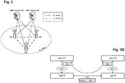
- Figure 3A provides a brief overview of a layer model on which the further discussion of the LTE architecture is based.
- the Open Systems Interconnection Reference Model (OSI Model or OSI Reference Model) is a layered abstract description for communication and computer network protocol design.
- the OSI model divides the functions of a system into a series of layers. Each layer has the property of only using the functions of the layer below, and only exporting functionality to the layer above.
- a system that implements protocol behavior consisting of a series of these layers is known as a 'protocol stack' or 'stack'. Its main feature is in the junction between layers which dictates the specifications on how one layer interacts with another. This means that a layer written by one manufacturer can operate with a layer from another. For the purposes of the invention, only the first three layers will be described in more detail below.
- the physical layer or layer 1 main purpose is the transfer of information (bits) over a specific physical medium (e.g. coaxial cables, twisted pairs, optical fibers, air interface, etc.). It converts or modulates data into signals (or symbols) that are transmitted over a communication channel.
- a specific physical medium e.g. coaxial cables, twisted pairs, optical fibers, air interface, etc.
- the purpose of the data link layer is to shape the information flow in a way compatible with the specific physical layer by breaking up the input data into data frames (Segmentation And Re-assembly (SAR) functions). Furthermore, it may detect and correct potential transmission errors by requesting a retransmission of a lost frame. It typically provides an addressing mechanism and may offer flow control algorithms in order to align the data rate with the receiver capacity. If a shared medium is concurrently used by multiple transmitters and receivers, the data link layer typically offers mechanisms to regulate and control access to the physical medium.
- SAR Segmentation And Re-assembly
- the data link layer is often subdivided into sublayers (e.g. RLC and MAC layers in UMTS).
- Typical examples of Layer 2 protocols are PPP/HDLC, ATM, frame relay for fixed line networks and RLC, LLC or MAC for wireless systems. More detailed information on the sublayers PDCP, RLC and MAC of layer 2 is given later. It is noted that in the present application the sublayers are also referred to as "layer” and thus the term "layer” employed herein does not necessarily mean a layer of the OSI model.
- the network layer or Layer 3 provides the functional and procedural means for transferring variable length packets from a source to a destination via one or more networks while maintaining the quality of service requested by the transport layer.
- the network layer's main purposes are inter alia to perform network routing, network fragmentation and congestion control functions.
- the main examples of network layer protocols are the IP Internet Protocol or X.25.
- Layers 4 to 7 it should be noted that depending on the application and service it is sometimes difficult to attribute an application or service to a specific layer of the OSI model since applications and services operating above Layer 3 often implement a variety of functions that are to be attributed to different layers of the OSI model. Therefore, especially in TCP(UDP)/IP based networks, Layer 4 and above is sometimes combined and forms a so-called "application layer".
- SDU service data unit
- PDU protocol data unit
- An SDU is a unit of information (data/information block) transmitted from a protocol at layer N+1 that requests a service from a protocol located at layer N via a so-called service access point (SAP).
- SAP service access point
- a PDU is a unit of information exchanged between peer processes at the transmitter and at the receiver of the same protocol located at the same layer N.
- a PDU is generally formed by a payload part consisting of the processed version of the received SDU(s) preceded by a layer N specific header and optionally terminated by a trailer. Since there is no direct physical connection (except for Layer 1) between these peer processes, a PDU is forwarded to the layer N-1 for processing. Therefore, a layer N PDU is, from a layer N-1 point of view, an SDU.
- the LTE layer 2 user-plane/control-plane protocol stack comprises three sublayers PDCP, RLC and MAC.
- each layer receives a SDU from a higher layer for which the layer provides a service and outputs a PDU to the layer below.
- the RLC layer receives packets from the PDCP layer. These packets are called PDCP PDUs from a PDCP point of view and represent RLC SDUs from an RLC point of view.
- the RLC layer creates packets which are provided to the layer below, i.e. the MAC layer.
- the packets provided by RLC to the MAC layer are RLC PDUs from an RLC point of view and MAC SDUs from a MAC point of view.
- the process is reversed, with each layer passing SDUs up to the layer above, where they are received as PDUs.
- the link-layer protocols enhance the service to upper layers by increased reliability, security and integrity.
- the link layer is responsible for the multi-user medium access and scheduling.
- IP Internet Protocol
- VoIP voice over IP
- TCP Transmission Control Protocol
- the Packet Data Convergence Protocol (PDCP) sublayer is responsible mainly for IP header compression and ciphering. In addition, it supports lossless mobility in case of inter-eNB handovers and provides integrity protection to higher layer-control protocols.
- the radio link control (RLC) sublayer comprises mainly ARQ functionality and supports data segmentation and concatenation. The latter two minimize the protocol overhead independent of the data rate.
- the medium access control (MAC) sublayer provides HARQ and is responsible for the functionality that is required for medium access, such as scheduling operation and random access.
- the Medium Access Control (MAC) layer is the lowest sublayer in the Layer 2 architecture of the LTE radio protocol stack and is defined by e.g. the 3GPP technical standard TS 36.321, current version 13.0.0.
- the connection to the physical layer below is through transport channels, and the connection to the RLC layer above is through logical channels.
- the MAC layer therefore performs multiplexing and demultiplexing between logical channels and transport channels: the MAC layer in the transmitting side constructs MAC PDUs, known as transport blocks, from MAC SDUs received through logical channels, and the MAC layer in the receiving side recovers MAC SDUs from MAC PDUs received through transport channels.
- the MAC layer provides a data transfer service (see subclauses 5.4 and 5.3 of TS 36.321 incorporated herein by reference) for the RLC layer through logical channels, which are either control logical channels which carry control data (e.g. RRC signaling) or traffic logical channels which carry user plane data.
- logical channels which are either control logical channels which carry control data (e.g. RRC signaling) or traffic logical channels which carry user plane data.
- control data e.g. RRC signaling
- traffic logical channels which carry user plane data.
- the data from the MAC layer is exchanged with the physical layer through transport channels, which are classified as downlink or uplink. Data is multiplexed into transport channels depending on how it is transmitted over the air.
- the Physical layer is responsible for the actual transmission of data and control information via the air interface, i.e. the Physical Layer carries all information from the MAC transport channels over the air interface on the transmission side. Some of the important functions performed by the Physical layer include coding and modulation, link adaptation (AMC), power control, cell search (for initial synchronization and handover purposes) and other measurements (inside the LTE system and between systems) for the RRC layer.
- the Physical layer performs transmissions based on transmission parameters, such as the modulation scheme, the coding rate (i.e. the modulation and coding scheme, MCS), the number of physical resource blocks etc. More information on the functioning of the physical layer can be found in the 3GPP technical standard 36.213 current version 13.0.0, incorporated herein by reference.
- the Radio Resource Control (RRC) layer controls communication between a UE and an eNB at the radio interface and the mobility of a UE moving across several cells.
- the RRC protocol also supports the transfer of NAS information.
- RRC connection control covers all procedures related to the establishment, modification and release of an RRC connection, including paging, measurement configuration and reporting, radio resource configuration, initial security activation, and establishment of Signalling Radio Bearer (SRBs) and of radio bearers carrying user data (Data Radio Bearers, DRBs).
- SRBs Signalling Radio Bearer
- DRBs Data Radio Bearers
- the radio link control (RLC) sublayer comprises mainly ARQ functionality and supports data segmentation and concatenation, i.e. RLC layer performs framing of RLC SDUs to put them into the size indicated by the MAC layer. The latter two minimize the protocol overhead independently from the data rate.
- the RLC layer is connected to the MAC layer via logical channels. Each logical channel transports different types of traffic.
- the layer above RLC layer is typically the PDCP layer, but in some cases it is the RRC layer, i.e. RRC messages transmitted on the logical channels BCCH (Broadcast Control Channel), PCCH (Paging Control Channel) and CCCH (Common Control Channel) do not require security protection and thus go directly to the RLC layer, bypassing the PDCP layer.
- BCCH Broadcast Control Channel
- PCCH Paging Control Channel
- CCCH Common Control Channel
- RLC When the RLC is configured to request retransmission of missing PDUs , it is said to be operating in Acknowledged Mode (AM). This is similar to the corresponding mechanism used in WCDMA/HSPA. Overall, there are three operational modes for RLC: Transparent Mode (TM), Unacknowledged Mode (UM), and Acknowledged Mode (AM). Each RLC entity is configured by RRC to operate in one of these modes.
- TM Transparent Mode
- UM Unacknowledged Mode
- AM Acknowledged Mode
- Transparent Mode no protocol overhead is added to RLC SDUs received from higher layer. In special cases, transmission with limited segmentation/reassembly capability can be accomplished. It has to be negotiated in the radio bearer setup procedure, whether segmentation/reassembly is used.
- the transparent mode is e.g. used for very delay-sensitive services like speech.
- Unacknowledged Mode data delivery is not guaranteed since no retransmission protocol is used.
- the PDU structure includes sequence numbers for integrity observations in higher layers. Based on the RLC sequence number, the receiving UM RLC entity can perform reordering of the received RLC PDUs. Segmentation and concatenation are provided by means of header fields added to the data.
- the RLC entity in Unacknowledged mode is unidirectional, since there are no associations defined between uplink and downlink. If erroneous data is received, the corresponding PDUs are discarded or marked depending on the configuration. In the transmitter, the RLC SDUs which are not transmitted within a certain time specified by a timer are discarded and removed from the transmission buffer.
- the RLC SDUs received from higher layer, are segmented/concatenated into RLC PDUs on sender side. On receiver side, reassembly is performed correspondingly.
- the unacknowledged mode is used for services where error-free delivery is of less importance compared to short delivery time, for example, for certain RRC signaling procedures, a cell broadcast service such as MBMS and voice over IP (VoIP).
- the RLC layer supports error correction by means of an Automatic Repeat Request (ARQ) protocol, and is typically used for IP-based services such as file transfer where error-free data delivery is of primary interest.
- RLC retransmissions are for example based on RLC status reports, i.e. ACK/NACK, received from the peer RLC receiving entity.
- the acknowledged mode is designed for a reliable transport of packet data through retransmission in the presence of high air-interface bit error rates. In case of erroneous or lost PDUs, retransmission is conducted by the sender upon reception of an RLC status report from the receiver.
- ARQ is used as a retransmission scheme for retransmission of erroneous or missed PDUs. For instance, by monitoring the incoming sequence numbers, the receiving RLC entity can identify missing PDUs. Then, an RLC status report can be generated at the receiving RLC side, and fed back to the transmitting RLC entity, requesting retransmission of missing or unsuccessfully decoded PDUs.
- the RLC status report can also be polled by the transmitter, i.e. the polling function is used by the RLC transmitter to obtain a status report from RLC receiver so as to inform the RLC transmitter of the reception buffer status.
- the status report provides positive acknowledgements (ACK) or negative acknowledgment information (NACK) on RLC Data PDUs or portions of them, up to the last RLC Data PDU whose HARQ reordering is complete.
- the RLC receiver triggers a status report if a PDU with the polling field set to '1' or when an RLC Data PDU is detected as missing.
- the receiver sends the RLC status report to the sender when triggered.
- L1/L2 control signaling is transmitted on the downlink along with the data.
- L1/L2 control signaling is multiplexed with the downlink data in a subframe, assuming that the user allocation can change from subframe to subframe.
- user allocation might also be performed on a TTI (Transmission Time Interval) basis, where the TTI length can be a multiple of the subframes.
- TTI length may be fixed in a service area for all users, may be different for different users, or may even by dynamic for each user.
- the L1/2 control signaling needs only be transmitted once per TTI. Without loss of generality, the following assumes that a TTI is equivalent to one subframe.
- the L1/L2 control signaling is transmitted on the Physical Downlink Control Channel (PDCCH).
- PDCCH Physical Downlink Control Channel
- a PDCCH carries a message as a Downlink Control Information (DCI), which in most cases includes resource assignments and other control information for a mobile terminal or groups of UEs.
- DCI Downlink Control Information
- Several PDCCHs can be transmitted in one subframe.
- the information sent in the L1/L2 control signaling for assigning uplink or downlink radio resources can be categorized to the following items:
- Downlink control information occurs in several formats that differ in overall size and also in the information contained in their fields as mentioned above.
- the different DCI formats that are currently defined for LTE are as follows and described in detail in 3GPP TS 36.212, "Multiplexing and channel coding", section 5.3.3.1 (current version v13.0.0 available at http://www.3gpp.org and incorporated herein by reference).
- the following DCI Formats can be used to carry a resource grant for the uplink.
- the uplink scheme allows for both scheduled access, i.e. controlled by eNB, and contention-based access.
- the UE In case of scheduled access, the UE is allocated a certain frequency resource for a certain time (i.e. a time/frequency resource) for uplink data transmission. However, some time/frequency resources can be allocated for contention-based access. Within these time/frequency resources, UEs can transmit without first being scheduled.
- One scenario where UE is making a contention-based access is for example the random access, i.e. when UE is performing initial access to a cell or for requesting uplink resources.
- the Node B scheduler assigns a user a unique frequency/time resource for uplink data transmission. More specifically the scheduler determines which UE(s) is (are) allowed to transmit, in which physical channel resources (frequency), and the corresponding transport format to be used by the mobile terminal for the transmission.
- the allocation information is signaled to the UE via the scheduling grant, sent on the L1/L2 control channel.
- the scheduling grant message contains information which part of the frequency band the UE is allowed to use, the validity period of the grant, and the transport format the UE has to use for the upcoming uplink transmission.
- the shortest validity period is one sub-frame. Additional information may also be included in the grant message, depending on the selected scheme. Only "per UE" grants are used to grant the right to transmit on the UL-SCH (i.e. there are no "per UE per RB" grants). Therefore, the UE needs to distribute the allocated resources among the radio bearers according to some rules. Unlike in HSUPA, there is no UE based transport format selection.
- the eNB decides the transport format based on some information, e.g. channel quality feedback, reported scheduling information and QoS info, and the UE has to follow the selected transport format.
- the usual mode of scheduling is dynamic scheduling, by means of downlink assignment messages for the allocation of downlink transmission resources and uplink grant messages for the allocation of uplink transmission resources; these are usually valid for specific single subframes. They are transmitted on the PDCCH using the C-RNTI of the UE. Dynamic scheduling is efficient for services types in which the traffic is bursty and dynamic in rate, such as TCP.
- a persistent scheduling is defined, which enables radio resources to be semi-statically configured and allocated to a UE for a longer time period than one subframe, thus avoiding the need for specific downlink assignment messages or uplink grant messages over the PDCCH for each subframe.
- Persistent scheduling is useful for services such as VoIP for which the data packets are small, periodic and semi-static in size.
- the overhead of the PDCCH is significantly reduced compared to the case of dynamic scheduling.
- the process by which a UE creates a MAC PDU to transmit using the allocated radio resources is fully standardized; this is designed to ensure that the UE satisfies the QoS of each configured radio bearer in a way which is optimal and consistent between different UE implementations.
- the UE Based on the uplink transmission resource grant message signaled on the PDCCH, the UE has to decide on the amount of data for each logical channel to be included in the new MAC and, if necessary, also to allocate space for a MAC Control Element.
- the simplest and most intuitive method is the absolute priority-based method, where the MAC PDU space is allocated to logical channels in decreasing order of logical channel priority. This is, data from the highest priority logical channel are served first in the MAC PDU, followed by data from the next highest priority logical channel, continuing until the MAC PDU space runs out.
- the absolute priority-based method is quite simple in terms of UE implementation, it sometimes leads to starvation of data from low-priority logical channels. Starvation means that the data from the low-priority logical channels cannot be transmitted because the data from high-priority logical channels take up all the MAC PDU space.
- a Prioritized Bit Rate (PBR) is defined for each logical channel, in order to transmit data in order of importance but also to avoid starvation of data with lower priority.
- the PBR is the minimum data rate guaranteed for the logical channel. Even if the logical channel has low priority, at least a small amount of MAC PDU space is allocated to guarantee the PBR. Thus, the starvation problem can be avoided by using the PBR.
- Constructing a MAC PDU with PBR consists of two rounds.
- each logical channel is served in decreasing order of logical channel priority, but the amount of data from each logical channel included in the MAC PDU is initially limited to the amount corresponding to the configured PBR value of the logical channel.
- the second round is performed.
- each logical channel is served again in decreasing order of priority.
- the major difference for the second round compared to the first round is that each logical channel of lower priority can be allocated with MAC PDU space only if all logical channels of higher priority have no more data to transmit.
- a MAC PDU may include not only the MAC SDUs from each configured logical channel but also a MAC CE. Except for a Padding BSR, the MAC CE has a higher priority than a MAC SDU from the logical channels because it controls the operation of the MAC layer. Thus, when a MAC PDU is composed, the MAC CE, if it exists, is the first to be included, and the remaining space is used for MAC SDUs from the logical channels. Then, if additional space is left and it is large enough to include a BSR, a Padding BSR is triggered and included in the MAC PDU.
- the Logical Channel Prioritization is standardized e.g. in 3GPP TS 36.321 (latest version v12.4.0) in subclause 5.4.3.1 incorporated herein. It is up to the UE implementation to decide in which MAC PDU a MAC control element is included when the UE is requested to transmit multiple MAC PDUs in one TTI.
- Buffer status reports from the UE to the eNodeB are used to assist the eNodeB in allocating uplink resources, i.e. uplink scheduling.
- uplink scheduling i.e. uplink scheduling.
- the eNB scheduler is obviously aware of the amount of data to be delivered to each UE; however, for the uplink direction, since scheduling decisions are done at the eNB and the buffer for the data is in the UE, BSRs have to be sent from the UE to the eNB in order to indicate the amount of data that needs to be transmitted over the UL-SCH.
- Buffer Status Report MAC control elements for LTE consist of either: a long BSR (with four buffer size fields corresponding to LCG IDs #0-3) or a short BSR (with one LCG ID field and one corresponding buffer size field).
- the buffer size field indicates the total amount of data available across all logical channels of a logical channel group, and is indicated in number of bytes encoded as an index of different buffer size levels (see also 3GPP TS 36.321 v 12.4.0 Chapter 6.1.3.1, incorporated herewith by reference).
- the long BSR reports the amount of data for four logical channel groups, whereas the short BSR indicates the amount of data buffered for only the highest logical channel group.
- the eNB assigns each logical channel to a logical channel group; preferably, logical channels with same/similar QoS requirements should be allocated within the same logical channel group.
- the UE sends a scheduling request (SR) to the eNodeB so as to be allocated with uplink resources to transmit the BSR.
- SR scheduling request
- PUCCH Physical Uplink Control Channel
- D-SR dedicated scheduling request
- RACH random access procedure
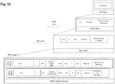
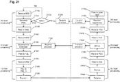
- Fig. 4 exemplary depicts the data flow of an IP packet through the link-layer protocols down to the physical layer.
- the figure shows that each protocol sublayer adds its own protocol header to the data units as well as the mapping of the transport block on a subrame.
- Transport block (TB) denotes the MAC PDU which is mapped onto the physical layer.
- the mapping of the transport block onto the subframe in LTE is performed within a so-called transmission time interval (TTI).
- TTI transmission time interval
- a single transport block is mapped in one TTi to one subframe in case of single input single output (SISO), i.e. transmitter and receiver operating with one antenna.
- SISO single input single output
- MIMO/MISO multiple input multiple output / multiple input single output
- two codewords corresponding to two transport blocks may be mapped in one TTI to the physical resources.
- more than two transport blocks may be considered for mapping.
- LTE L2 functions are summarized in the following table: Table 1: LTE L2 functions (Tx side) UP Protocol layer Functions PDCP Bearer mapping (EPS bearer-> radio bearer) Sequence numbering Header compression Security Routing RLC Sequence numbering Segmentation Concatenation ARQ MAC Scheduling Multiplexing HARQ
- the RLC layer performs concatenation/segmentation of PDCP PDUs.
- the MAC layer performs logical channel prioritization (LCP) to determine how much data each RLC-entity should transmit (provide to the lower layers, i.e. to the MAC/PHY).
- LCP logical channel prioritization
- Each RLC entity provides one RLC PDU containing one or more RLC SDUs.
- a corresponding L-field is added, which enables the receiver to extract the corresponding SDUs. If the last contained RLC SDU does not fit entirely into the RLC PDU, it is segmented, i.e., the remainder of the RLC SDU will be sent in the subsequent RLC PDU(s).
- the RLC sequence number (SN) is added to the RLC PDU header.
- MAC multiplexes the RLC PDUs for different logical channel identifiers (LCIDs) and adds a corresponding sub-header with the LCID and the L-field.
- LCIDs logical channel identifiers
- FIG 4 A high level illustration of the transport block structure is illustrated in Figure 4 .Recently, the 3GPP has started to study and work on the 5 th generation system under the name new radio (NR). NR targets very high data rates (currently up to 20 Gbit/sec in downlink and 10 Gbit/sec in uplink).
- a PDCP PDU can be generated once a PDCP SDU (i.e. an IP packet) is available, i.e. PDCP PDU generation can be done in a non-real-time manner, i.e. irrespectively of whether or not there are currently resources granted for the PDCP PDU.
- RLC and MAC PDUs can only be generated in real-time manner (i.e. after reception of the UL grant).
- Segmentation, concatenation and multiplexing are required for DL/UL data SDUs to fit within the total size of assigned TB size determined by scheduler.
- Concatenation and segmentation requires knowledge of the scheduling decision/grant size before it can be performed so it is subject to strict real time processing requirements. This also implies that the transmitter cannot do any pre-processing for either the RLC or the MAC layer, e.g., of sub-headers/headers before the scheduling / grant information. The inability to perform "pre-processing" incurs a processing delay upon grant reception. If the RLC and to some extent MAC processing could be completed beforehand (the grant reception), then the delay in MAC TB submission to PHY layer would be, comparatively, much smaller.
- one of the design goals for the U-Plane protocol architecture is to reduce the Layer-2 protocol overhead.
- the Length field is included twice, once in RLC and once in MAC, which increases header overhead.
- PDCP and RLC use their own sequence numbers in the existing LTE protocol architecture, which also increases header overhead.
- the aim of the present disclosure is to provide an approach improving the efficiency of the layer processing.
- a data transmitting node for transmitting data over a wireless interface in a communication system to a data receiving node, comprising: a third layer processing unit for performing an automatic repeat request, ARQ, retransmission according to a status report fed back from the data receiving node and for re-segmenting or not data to be retransmitted based on segment length information included in the status report including adding to the data a segmentation control information; a second layer processing unit for receiving, from the third layer processing unit, a third layer data unit, segmenting the third layer data unit based on a resource allocation and forming a plurality of second layer data units including the respective segments of the third layer data unit and the segmentation control information which is modified if re-segmentation is to be applied; and a first layer processing unit for receiving from the second layer one or more of the plurality of the second layer data units and mapping the one or more of the plurality of the second layer data units onto the resources allocated for data transmission.
- a data transmitting node for transmitting data over a wireless interface in a communication system to a data receiving node, comprising: a third layer processing unit for performing an automatic repeat request, ARQ, retransmission according to a status report fed back from the data receiving node; a second layer processing unit for receiving, from the third layer processing unit, a third layer data unit, segmenting the third layer data unit according to the status report and based on a resource allocation and forming a plurality of second layer data units including the respective segments of the segmented third layer data unit; and a first layer processing unit for receiving from the second layer one or more of the plurality of the second layer data units and mapping the one or more of the plurality of the second layer data units onto the resources allocated for data transmission.
- a data receiving node for receiving data over a wireless interface in a communication system from a data transmitting node, comprising: a first layer processing unit for de-mapping one or more of a plurality of second layer data units from the resources allocated for data transmission and for providing the one or more of the plurality of the de-mapped second layer data units to a second layer processing unit; the second layer processing unit for performing de-multiplexing of a plurality of third layer unit segments and segmentation control information from the one or more of the plurality of second layer data units, and forwarding the plurality of the demultiplexed third layer unit segments together with the segmentation control information to a third layer processing unit; the third layer processing unit for performing re-ordering of the plurality of the demultiplexed third layer unit segments and assembly of the demultiplexed third layer unit segments into a third layer data unit.
- a method for transmitting data over a wireless interface in a communication system to a data receiving node comprising: performing a third layer processing including performing an automatic repeat request, ARQ, retransmission according to a status report fed back from the data receiving node and for re-segmenting or not data to be retransmitted based on segment length information included in the status report including adding to the data a segmentation control information; performing a second layer processing including receiving, from the third layer processing unit, a third layer data unit, segmenting the third layer data unit based on a resource allocation and forming a plurality of second layer data units including the respective segments of the third layer data unit and the segmentation control information which is modified if re-segmentation is to be applied; and performing a first layer processing including receiving from the second layer one or more of the plurality of the second layer data units and mapping the one or more of the plurality of the second layer data units onto the resources allocated for data transmission.
- a method for transmitting data over a wireless interface in a communication system to a data receiving node comprising: a third layer processing including performing an automatic repeat request, ARQ, retransmission according to a status report fed back from the data receiving node; a second layer processing including receiving, from the third layer processing unit, a third layer data unit, segmenting the third layer data unit according to the status report and based on a resource allocation and forming a plurality of second layer data units including the respective segments of the segmented third layer data unit; and a first layer processing including receiving from the second layer one or more of the plurality of the second layer data units and mapping the one or more of the plurality of the second layer data units onto the resources allocated for data transmission.
- a method for receiving data over a wireless interface in a communication system from a data transmitting node comprising: a first layer processing including de-mapping one or more of a plurality of second layer data units from the resources allocated for data transmission and for providing the one or more of the plurality of the de-mapped second layer data units to a second layer processing unit; the second layer processing including performing de-multiplexing of a plurality of third layer unit segments and segmentation control information from the one or more of the plurality of second layer data units, and forwarding the plurality of the demultiplexed third layer unit segments together with the segmentation control information to a third layer processing unit; the third layer processing including performing re-ordering of the plurality of the demultiplexed third layer unit segments and assembly of the demultiplexed third layer unit segments into a third layer data unit.
- a computer readable medium for storing therein instructions, which when executed on a computer, cause the computer to perform the steps of the above methods.
- a mobile station or mobile node or user terminal or user equipment is a physical entity within a communication network.
- One node may have several functional entities.
- a functional entity refers to a software or hardware module that implements and/or offers a predetermined set of functions to other functional entities of a node or the network.
- Nodes may have one or more interfaces that attach the node to a communication facility or medium over which nodes can communicate.
- a network entity may have a logical interface attaching the functional entity to a communication facility or medium over which it may communicate with other functional entities or correspondent nodes.
- radio resources as used in the set of claims and in the application is to be broadly understood as referring to physical radio resources, such as time-frequency radio resources.
- the following exemplary embodiments provide an improved radio interface layer processing for the new radio technology envisioned for the 5G mobile communication systems.
- very few details have been agreed on with regard to the 5G mobile communication system, such that many assumptions have to be made in the following in order to be able to explain the principles underlying the embodiments. These assumptions are however to be understood as merely examples that should not limit the scope of the disclosure.
- a skilled person will be aware that the principles of the invention as laid out in the claims can be applied to different scenarios and in ways that are not explicitly described herein.
- the new radio technology will be evolving from the radio technology already defined for LTE(-A), although several changes can be expected so as to meet the requirements for 5G mobile communication systems.
- the concatenation/segmentation functionality is moved from the RLC layer to the MAC entity.
- This approach provides some advantages, for instance, the RLC PDUs and partly the MAC PDUs can be pre-constructed at the terminal (if the transmission is performed in the uplink), before an UL grant is received. This reduces processing time through pre-constructing the respective RLC PDU and partly MAC PDU.
- the RLC layer does not have to wait for MAC scheduling decision and the RLC PDU size indication (both carried with resource allocation by L1/L2 signaling). This reduces the processing time in generating the transport block.
- Figure 5A shows the main functions of protocol layers on the transmitter (TX) and the receiver (RX) sides. As can be seen, at the transmitter side, the segmentation is performed in MAC layer, in cooperation of the RLC layer.
- FIG. 5B illustrates basic operation performed on the transmitter side:
- MAC also decides, based on logical channel prioritization procedure (LCP), which of the corresponding MAC PDUs are to be provided to the physical layer at which time point.
- LCP logical channel prioritization procedure
- One example of a LCP procedure is known from the LTE and referred to above in the background section. Nevertheless, the present invention is not limited thereto and in general
- the above approach is applicable not only to the AM, but also to UM.
- UM In the case that UM is applied, there are no retransmissions on the RLC layer. Nevertheless, at the receiver side, if a RLC PDU or a RLC PDU segment is missing, the RLC SDU is still assemblied and provided to the PDCP layer.
- the TX side RLC submits the corresponding missing RLC PDU and/or PDU segment to the MAC layer including a suitable header to assist the receiver in reassembly of the segment(s) by retransmitting it.
- the RLC layer may submit the whole RLC PDU to the MAC layer, even if just a segment of the corresponding RLC PDU was indicated as missing; in addition, the RLC layer shares the Status Report details (i.e. the entire status report) with the MAC layer.
- An advantage of this approach is to reduce RLC header overhead. If the re-segmentation is done in the RLC layer, then the RLC layer adds segmentation header fields which increases header overhead. To overcome this problem, the complete RLC PDU is sent to MAC and MAC performs segmentation based the on status report.
- the status report of RLC is understood by MAC since universal (common) sequence number is being used between the layers (PDCP, RLC, MAC). In this case, the MAC layer performs the re-segmentation based on this knowledge and the result of the LCP, and includes a suitable header to assist the receiver in reassembly of the segment(s).
- the framework may be seen as a protocol stack in which there a first layer responsible for mapping/de-mapping of the data onto/from the physical resources (corresponding to the physical layer), a second layer (corresponding to MAC) and a third layer (corresponding to RLC and/or PDCP). It is noted that the terms “first layer”, “second layer” and “third layer” here do not necessarily correspond to the OSI model layers.
- the reduction of protocol stack processing latency can be achieved in a transmitter side with a first, physical, layer; a second layer; and a third layer in that the second layer receives from the third layer pre-processed third layer PDUs (generated by the third layer without knowledge of the resource allocation) and receives (from the receiver in uplink or internally in downlink) resource allocation for the physical layer.
- the pre-processed third layer PDUs may be added (already at the third layer or at the second layer) a header including segmentation information. It is noted that such pre-processed third layer PDUs may be provided for a plurality of third layer entities, corresponding to a plurality of logical channels which may have different priorities. Accordingly, the second layer then may perform a prioritization procedure.
- the second layer Based on the received resource allocation and possibly also based on the result of prioritization procedure, the second layer then provides the first layer with the suitable preprocessed third layer PDUs including the segmentation information as the second layer header at a first time point t1 and possibly performs further segmentation of the pre-processed PDUs and modifies the segmentation information in the header accordingly before providing the data to the first layer at a time point t2 later than the time point t1.
- the third layer PDUs received at the second layer may be already pre-segmented according to ARQ status report if the third layer implements ARQ. But this approach is also applicable if the third layer does not implement ARQ. The pre-segmentation may then be done based on some statistic measures of past allocations or according to another rule or does not have to be performed at all.
- Multi-Connectivity is a mode of operation whereby a multiple Rx/Tx UE in the connected mode is configured to utilize radio resources amongst E-UTRA and NR provided by multiple distinct schedulers connected via a non-ideal backhaul.
- a layer above the third layer in the transmitter such as a terminal
- the two or more base stations then receive the same packet independently, thus increasing the probability of correct reception by the network.
- dual connectivity is used to refer to an operation where a given UE consumes radio resources provided by at least two different network nodes connected with non-ideal backhaul.
- a UE is connected with both macro cell (macro eNB) and small cell (secondary eNB).
- macro eNB macro cell
- secondary eNB small cell
- each eNB involved in dual connectivity for a UE may assume different roles. Those roles do not necessarily depend on the eNB's power class and can vary among UEs.
- the same IP/PDCP packet is transmitted over a plurality of links / cells.
- the multiple receiving eNBs one is functioning as a master eNB, which implements the layer that performs the reassembly of the segments received via multiple connections.
- the master eNB communicates with the other eNBs.
- the PDCP layer takes over the reassembly function in addition to other functions that it is already performing upon switching from single to multi connectivity.
- the ARQ may still run at the RLC layer (in the AM) and in this case the PDCP layer will need to share the missing (fully or partially) PDCP SN details with the RLC layer.
- the PDCP layer will inform the RLC layer about missing part of segments.
- the receiving entity of the RLC layer will send status report to transmitting entity of the RLC layer. Therefore, a separate ARQ in RLC and PDCP layer is not required, which means single connectivity and multi-connectivity, ARQ may both run in RLC layer.
- the PDCP layer can compose its own Status Report and send it to the TX- PDCP entity.
- the Status Report shall contain information on the missing PDCP PDUs and/ or PDU segments.
- the present disclosure provides an efficient layer model to be implemented at the transmitter and the receiver side. This includes one or more of the following:
- a data transmitting node for transmitting data over a wireless interface in a communication system to a data receiving node.
- the data transmitting node comprises a third layer processing unit for performing or not an ARQ retransmission according to a status report fed back from the data receiving node and for re-segmenting or not data to be retransmitted (if any) based on segment length information included in the status report.
- the re-segmentation includes adding to the segmented data segmentation control information, for instance as a header.
- This header is also advantageously interpreted and used in a second layer, provided to the second layer together with the third layer data unit.
- the retransmission protocol is handled by the third layer, which does not exclude application of independent ARQ/HARQ protocols in other layers below or above the third layer.
- the data transmitting node further comprises a second layer processing unit for receiving, from the third layer processing unit, a third layer data unit, segmenting the third layer data unit based on a resource allocation and forming a plurality of second layer data units including the respective segments of the third layer data unit and the segmentation control information which is modified if re-segmentation is to be applied.
- the resource allocation may be either received from the data receiving node or generated at the data transmitting node. For instance, if the transmitting node is terminal (UE), the resource allocation (uplink grant) may be received from a base station, i.e. from the data receiving node.
- the transmitting node is a base station
- the resource allocation for the transmission may be generated at the base station, and provided to the MAC layer.
- the present disclosure is also applicable to direct communication between terminals or between relays and terminals or relays and base stations.
- the data transmitting node comprises a first layer processing unit for receiving from the second layer one or more of the plurality of the second layer data units and mapping the one or more of the plurality of the second layer data units onto the resources allocated for data transmission.
- the data transmitting node may further comprise a fourth layer processing unit for providing sequence number within its header.
- the sequence number is increased for each new fourth layer SDU, i.e. with each IP packet, the increasing may be cyclical while the sequence number has a predefined maximum value.
- the third layer advantageously does not provide another sequence number but encapsulates the fourth layer processing unit including the sequence number provided by the PDCP layer.
- the first layer may be the physical layer
- the second layer may be the MAC layer
- the third layer may be the RLC layer
- the fourth layer may be the PDCP.
- the third layer may also be considered to be the PDCP layer in some embodiments or one combined layer with functions of both RLC and PDCP especially in case of architectures evolving based from the present LTE.
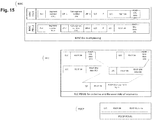
- FIG. 6 illustrates processing at a transmitter side according to this embodiment and exemplified using LTE terminology.
- the transmitter side may be the terminal transmitting data in the uplink to a base station.
- the present disclosure is not limited thereto and the transmitting side may be a terminal transmitting data to another terminal or to any other node.
- the present disclosure may also be applied to a base station or a relay node or another node being the data transmitter.
- an IP packet 1 with the length of 1200 bytes is provided to the PDCP layer, thus forming a PDCP SDU.
- the PDCP SDU is added a header including a D/C indicator which may be a single bit. This bit indicates whether the content of the PDCP PDU is a Data or Control PDU. In this example, it is set (i.e. the bit is equal to 1) for data PDU and unset (i.e. the bit is equal to 0) for control PDU. However, in general, the setting/unsetting may be reversed.
- the PDCP header further includes the PDCP sequence number (SN).
- the PDCP PDU1 (with a payload of 1200 bytes) is sent to the RLC layer, thus forming an RLC SDU.
- the RLC layer includes the relevant RLC header to the RLC PDU.
- the RLC header includes another D/C flag, a P flag and an RF flag.
- the D/C flag indicates whether control or data are carried by the RLC PDU, while the P flag is a polling bit which is set to request a status report from the receiver (peer RLC entity). If it is not set then a status report is not requested.
- the RF flag is a re-segmentation flag indicating whether the RLC PDU is a complete PDCP PDU or a PDCP PDU segment.
- the RF value is initially set to 0, indicating that the RLC PDU is a complete PDU, and then delivered to the MAC layer as a part of the RLC PDU1.
- the RLC layer does not perform segmentation; rather the MAC layer performs the segmentation. Accordingly, for the first transmission, the RF value is always set to 0.
- the transmitting MAC entity needs to segment the RLC PDU based on the grant received.
- the grant sizes assumed in this example are 800 and 400 bytes at two different transmission occasions (or at least one grant for 800 bytes and the rest waiting for another grant).
- the MAC layer segments the RLC PDU corresponding to a MAC SDU.
- the transmitting MAC entity includes segmentation-relevant MAC header portions into the respective MAC PDUs to indicate segment offset (SO) and last segment field (LSF) of the included RLC PDU and forms the MAC PDUs which are referred as MAC PDU1 and MAC PDU2 in Figure 6 .
- MAC PDU1 contains an 800 byte payload whereas MAC PDU2 contains a 400 byte payload.
- MAC PDU1 and MAC PDU2 are sent to TTI0 and TTI1 respectively.
- the TTI0 and TTI1 are then multiplexed into different resources, for instance different time resources.
- this is not to limit the present disclosure to mapping the two MAC PDUs to different time points. More than one MAC PDU may be generally mapped onto different type of resources, for instance different frequencies or different streams of a MIMO system, orthogonal codes, or the like.
- the SO field in this example indicates the position of the PDU segment in bytes within the original PDU. Specifically, the SO field indicates the position within the data field of the original PDU to which the first byte of the data field of the PDU segment corresponds to. The first byte in the data field of the original PDU is referred by the SO field value zero.
- the LSF field indicates whether or not the last byte of the PDU segment corresponds to the last byte of an PDU.
- the MAC layer may include into the MAC PDU1 and MAC PDU2 further fields such as logical channel ID (LCID) and an extension flag (E), which indicates whether or not there are other fields following the MAC header.
- LCID logical channel ID
- E extension flag
- Value 1 indicates that there is at least one or more E/LCID fields following this field.
- Value 0 indicates that there is no more E/LCID fields following this field implying that the next byte is the start byte of the MAC SDU.
- There may some further fields or reserved fields in the header (not shown in the figure).
- a data receiving node for receiving data over a wireless interface in a communication system from a data transmitting node.
- the data receiving node comprises a first layer processing unit for de-mapping one or more of a plurality of second layer data units from the resources allocated for data transmission and for providing the one or more of the plurality of the de-mapped second layer data units to a second layer processing unit.
- the data receiving node further comprises the second layer processing unit for performing de-multiplexing of a plurality of third layer unit segments and segmentation control information from the one or more of the plurality of second layer data units, and forwarding the plurality of the demultiplexed third layer unit segments together with the segmentation control information to a third layer processing unit.
- the data receiving node further comprises the third layer processing unit for performing re-ordering of the plurality of the demultiplexed third layer segments and assembly into a third layer unit.
- the segmentation information which is a part of the second layer data units (and may be, in particular carried in the second layer header) is also looked at and used at the third layer.
- This approach disregards thus the strict layer separation on one hand; on the other hand it saves overhead and enables to efficiently perform the re-ordering and re-assembly at the third layer. This is particularly advantageous if the ARQ procedure is implemented in the third layer, which - however - is not necessary and not limiting for the present invention.
- the third layer processing unit in the data receiving apparatus is further configured to generate control data carrying a status report indicating whether or not at least one third layer unit segment has been received correctly.
- the status report may include at least one of positive acknowledgements or negative acknowledgements for at least one third layer data unit and/or identification of correctly received or missing segments of the third layer data unit.
- Exemplary format of the status report which may be employed here can be found in 3GPP TS 36.322, Version 13.2.0, Section 6.2.1.6 However, it is noted that this is only an example and the status report may have a different format and content as long as it enables positive and/or negative reception acknowledgement for a third layer PDU or its segments.
- FIG. 7 illustrates an exemplary reception processing of MAC PDU1 and MAC PDU2 received over an error prone channel.
- MAC PDU1 is received (800 bytes payload) correctly but MAC PDU2 (400 bytes payload) is lost (could not been decoded correctly, i.e. the CRC failed).
- the MAC layer performs de-multiplexing of the RLC PDU1 and sends it to RLC layer.
- the RLC layer then performs reassembling and reordering of the MAC segments.
- the RLC receiving side (RX) sends status report indicating correct reception of the 800 to 1200 bytes belonging to the MAC PDU1 to the RLC transmitting side (TX).
- the re-ordering and re-assembling of the RLC PDU segments is performed based on the header information from the MAC layer. This includes in the example of Fig. 7 in particular the segment offset and the LSF indicator.
- the RLC layer D/C field enables distinguishing between the RLC data PDUs and RLC control PDUs such as status reports.
- FIG 8 shows the exemplary subsequent actions at the RLC transmitting side, assuming that the transmitter side is aware of the second missing MAC-PDU2 segment (for instance based on the status report).
- the RLC TX takes the complete RLC PDU of the corresponding missing packet from the transmission buffer and performs a new segmentation (re-segmentation) of the 400 (800 to 1200) bytes which are indicated by the RLC status report as missing.
- the re-segmentation includes also attaching the appropriate RLC header.
- the RLC header here includes the segment offset which indicates the position of the RLC PDU segment which is to be retransmitted by means of an offset in bytes.
- the segmentation offset SO 801 since the missing 400 bytes from 801 to 1200 are to be retransmitted.
- the re-segmented RLC PDU corresponding to the missing 400 bytes is delivered to the MAC layer.
- the MAC layer then performs segmentation of the received RLC PDU and forms MAC PDU1 (which contains 200 bytes of data) and MAC PDU2 (which also contains 200 bytes of data), which are then sent to TTI0 and TTI1 respectively - as described above with reference to Figure 6 for the first transmission.
- the MAC layer only performs segmentation if it is required.
- the grant size is not sufficient and that is why the MAC layer forms MAC PDU1 and MAC PDU2. If the allocation is sufficient, no segmentation is needed, or possibly, concatenation is performed (in case the allocation is larger than needed for one MAC PDU).
- the MAC layer reads the SO field and the LSF field from the RLC header and modifies them on the basis of the grant size, i.e. in this example to reflect the segmentation size of 200 bytes and 200 bytes, respectively.
- Figure 9 illustrates an example in which the MAC PDU1 and MAC PDU2 from Fig. 8 are both received correctly.
- the MAC layer delivers the correctly received MAC PDU1 and MAC PDU2 to the RLC layer.
- the RLC layer performs the reordering and reassembling of MAC segments and then delivers the complete PDCP PDU to the PDCP layer.
- the reordering is performed based on the sequence numbers (SN). As mentioned above, a single sequence number is advantageously used for both PDCP and RLC layers in order to save overhead.
- the RLC RX collects all segments of the RLC PDU (retransmitted or correctly received after the first transmission), re-orders them based on the MAC header information and reassembles the RLC PDU.
- the reassembled PDU may then be provided to the higher layers (such as PDCP or directly IP, if there is no PDCP) for further processing.
- Table 2 NR protocol stack tasks UP protocol layer Functions PDCP TX - Header compression - SN attached - Ciphering - Retransmission RLC TX - Delivering packets to MAC layer - Packet (re)-segmentation on retransmission MAC TX - Concatenation/multiplexing - Segmentation - HARQ transmission MAC RX - HARQ reception - De-multiplexing RLC RX - MAC segment reordering/status reporting (Retransmission) - Packet reassembly -Out of sequence delivery to PDCP PDCP RX - Packet deciphering - Complete PDU based reordering/status reporting - Header decompression
- Tables 3-5 provide examples of the headers of the respective layers PDCP, RLC and MAC.
- Table 3 The description of the PDCP header fields Data/Control bit (D/C) D/C indicates whether PDU is data or control PDU Sequence number (SN) 10 bit sequence number
- Table 4 The description of the RLC header fields Data/Control bit (D/C) D/C indicates whether PDU is data or control PDU Re-segmentation flag (RF) RF indicates whether PDU is complete or segment PDU.
- Polling bit (P) The P field indicates whether or not the transmitting side of an AM RLC entity requests a STATUS report from its peer.
- LSF Last segment field
- the length of the sequence number is exemplified as 10 bits. However, it is noted that this is only an example which is not to limit the present invention.
- the length of the PDCP sequence number can be 5 bit, 7 bits or 12 bits depending on the radio bearer's characteristics.
- the length of the sequence number is a matter of system design as is clear to those skilled in the art any may be selected to have any length for the purposes of the present invention.
- the PDCP PDUs are sent to the RLC layer at the receiver.
- the PDCP, RLC and MAC layers use a universal sequence number which is understood by all these layers.
- the PDCP sequence number is used, which is understood by all three layers, or at least the PDCP and RLC since the SN is not necessarily needed in the lower layers.
- the RLC layer includes the relevant RLC header in the RLC PDU, for instance the RF field to indicate a complete or segmented PDU.
- the RF value is initially set to 0 and is updated when a status report arrives at the RLC TX.
- the transmitting side transmits the RLC data PDUs, it still stores the RLC PDUs in the retransmission buffer for possible retransmission. A retransmission may be requested by the receiver by means of the status report.
- the RLC PDUs are then delivered to the MAC layer. Afterwards, the transmitting MAC entity performs segmentation and/or concatenation on the MAC SDU received from the upper layer (RLC) to form the MAC PDU(s).
- the size of the MAC PDU at each transmission opportunity (TTI) is decided and notified by the MAC layer itself depending on the radio channel conditions and transmission resources available therefor.
- dynamic scheduling may be applied for the shared channel so that in each TTI a different allocation is possible (capable of accommodating different amount of date for instance due to varying modulation and coding scheme for better link adaptation).
- the size of each transmitted MAC PDU can thus be different.
- the transmitting MAC entities include RLC PDUs/MAC SDUs into a MAC PDU in the order, in which they arrive at the MAC entity. Therefore a single MAC PDU can contain complete RLC PDUs or an RLC PDU segment since MAC may perform not only segmentation but also concatenation, depending on the respective segment sizes and allocated resources. If a MAC PDU contains N (N being an integer larger than 0) RLC PDUs and/or PDU segments, then the MAC layer shall include N-1 Length fields (L-fields) for all respective corresponding RLC PDUs and/or PDU segments i.e. one L-field for each RLC PDUs and/or PDU segments except for the last one.
- N being an integer larger than 0
- the MAC layer knows where the actual data starts since it knows both the header length, as well as - with the L-field - the MAC PDU length.
- the header length is assumed to be known here. For instance, it may be predefined (for instance specified in a standard) and/or indicated within a field in the header.
- the extension bit is used to indicate whether the header continues or terminates, which makes possible to determine the header size.
- the MAC layer performs de-multiplexing of the MAC PDUs without removing the segmentation fields (SO and LSF) and then the de-multiplexed RLC PDUs/segments are delivered to the RLC layer.
- the receiving RLC layer receives the RLC PDU segments, it first reorders and re-assemblies them if they are received out of sequence (cf. also Figure 9 ).
- One of the advantages of not doing reordering and reassembling in the MAC layer is the processing time reduction. If one segment is missed in the receiver side, then the MAC layer could not do reassembly and reordering which will add delay in delivery to the upper layer (RLC).
- the MAC layer passes the segmentation fields (SO, LSF) to the RLC layer since segmentation and concatenation are performed by the MAC layer, as described above with reference to Figure 6 . Therefore, the RLC layer reads the segmentation header field(s) received from the MAC layer and on the basis of the segmentation (e.g. SO, LSF) and concatenation (e.g. LI) header field(s), the RLC layer performs, where appropriate, the re-ordering and re-assembling. Accordingly, a cross-layer interaction is required in this example since the receiving RLC layer has to know and use the MAC layer signaling fields.
- segmentation e.g. SO, LSF
- concatenation e.g. LI
- RLC PDUs received out of sequence at the MAC layer are delivered to the upper layer (RLC).
- An ARQ operation is performed in the receiving RLC to support an error free transmission (acknowledged mode).
- the receiver side provides an RLC status report to the transmitting side indicating the missing PDU(s) or PDU segment(s) information for the RLC PDUs.
- the transmitter of the RLC layer takes the complete RLC PDU of the corresponding missing packet from the transmission buffer and performs (re)-segmentation on the basis of the missing segment(s) which is/are indicated by the RLC status report. If re-segmentation is performed after the reception of the status report, the RLC changes the RF field from 0 to 1. Then the (re)-segmented PDU(s) is/are delivered to the MAC layer, which reads the RF flag.
- the missing segment PDU or PDUs may have to be broken up into smaller segmentations (re-segmented) before retransmission (which is done by MAC layer).
- the re-segmentation is performed in the MAC layer.
- a data transmitting node for transmitting data over a wireless interface in a communication system to a data receiving node.
- the data transmitting node comprises a third layer processing unit for performing an automatic repeat request, ARQ, retransmission according to a status report fed back from the data receiving node.
- the data transmitting node further comprises a second layer processing unit for receiving, from the third layer processing unit, a third layer data unit, segmenting the third layer data unit according to the status report and based on a resource allocation and forming a plurality of second layer data units including the respective segments of the segmented third layer data unit.
- the first layer processing unit is also present for receiving from the second layer the plurality of the second layer data units and mapping the plurality of the second layer data units onto the resources allocated for data transmission.
- the segmentation functionality is entirely transferred to the second layer, the closest layer to the physical layer. This is illustrated in Figure 10 in a greater detail based on a selected example.
- the RLC layer of the transmitter adds the PDCP PDU (RLC SDU) a header including the polling bit (if this embodiment is applied with AM rather than UM) to request a status report and the D/C field indicating whether the RLC PDU carries payload (user) or control data. It is noted that the present disclosure is not limited to the RLC layer preforming ARQ since the RLC layer may also operate in the unacknowledged mode.
- the RLC TX layer delivers the status report received from the RLC RX to the MAC layer.
- the MAC layer reads the segmentation information such as the sequence number (SN), SOstart and SOend value form the status report and performs the segmentation accordingly. Therefore, the RLC TX takes the complete RLC PDU from the retransmission buffer and sends it to the MAC TX. This is illustrated in Figure 10 which shows the RLC PDU including the data field with PDCP SDU data of 1200 bytes rather than only the 400 bytes as shown in Figure 8 .
- the MAC TX layer performs the segmentation on the basis of the segentation information, e.g. SOstart, SOend and SN which is indicated by the RLC status report and forwarded down to the MAC layer by the RLC layer as shown in Figure 10 .
- the MAC PDU header is generated.
- the header in Fig. 10 includes the LCID (logical channel identification), the E-bit indicating whether or not further header information is present and the segmentation information including here the segment offset (may be in the units of bytes) which indicates the start of the carried segment within the RLC PDU and the last segment field (LSF) indicating whether or not the encapsulated RLC PDU segment is the last in the RLC PDU.
- the offsets of 801 and 1001 doe the two segments of 200 and 200 bytes respectively are signaled.
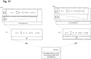
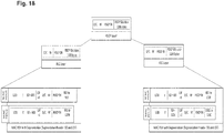
- FIG 11A shows a status report (STATUS PDU) as defined in the 3GPP TS 36.322, v. 13.2.0.
- STATUS PDU consists of a STATUS PDU payload and a RLC control PDU header.
- RLC control PDU header consists of a D/C and a CPT field.
- the STATUS PDU payload starts from the first bit following the RLC control PDU header, and it consists of one ACK_SN and one E1, zero or more sets of a NACK_SN, an E1 and an E2, and possibly a set of a SOstart and a SOend for each NACK_SN. When necessary one to seven padding bits are included in the end of the STATUS PDU to achieve octet alignment.
- Figure 11B shows an exemplary format of an RLC status report.
- This exemplary status report is similar and includes similar fields as the LTE status report which is exemplified in Fig. 11A .
- the status report of Fig. 11B differs from the LTE status report in Fig. 11A in that the PDCP sequence number is conveyed rather than the RLC sequence number.
- the status report includes a D/C field and a CPT (control PDU type) field which indicates whether or not the PDU is a status PDU, it indicates the status PDU for the status report.
- PDCP ACK_SN is a 10 bits long field which indicates the SN of the next not received RLC Data PDU which is not reported as missing in the status report (STATUS PDU).
- Extension bit 1 indicates whether or not a set of PDCP NACK_SN, E1 and E2 follows; if set to 0 - a set of NACK_SN, E1 and E2 does not follow; if set to 1 - a set of NACK_SN, E1 and E2 follows.
- Negative Acknowledgement SN indicates the SN of the RLC PDU (or portions of it) that has been detected as lost at the receiving side of the AM RLC entity.
- Extension bit 2 indicates whether or not a set of SOstart and SOend follows; if set to 0 - a set of SOstart and SOend does not follow for this NACK_SN; if set to 1 - a set of SOstart and SOend follows for this NACK_SN.
- the SOstart and SOend indicate respectively the start and the end of the negatively acknowledged RLC PDU segments.
- segment offsets start and end together which are typically 30 bits long which increases MAC sub-header overhead, especially for smaller segments.
- the segment identification is thus a segment number indicating a sequence number of the segment of the third layer data unit within the third layer data unit.
- This segment number may be used in the data PDUs as illustrated in the Figures, i.e. instead of the SO field. However, the segment number may also be advantageously used in the status report (STATUS PDU) to replace the SOstart and SOend.
- the MAC sub-header (i.e. portion of the header related to segmentation) is reduced by using a 4 bit long segment number instead of the 30 bit segment offsets (15 bits of SOstart and 15 bits SOend).
- the MAC layer performs segmentation on the basis of the 4 bits indicating the segment number.
- the 4 bit segment number allows distinguishing a maximum of 16 segments. However the number 4 is only for exemplary purposes here. If more or less segments are necessary for the corresponding user plane layer architecture, this could be done using a higher number of bits.
- the approach of this embodiment is to reduce the overhead by signaling a segment number for each segment instead of the start and end of each segment within the RLC PDU. Since the number of segments is certainly smaller than the number of bits in the RLC PDU to which the offsets are related, overhead is generally saved by addressing the segments rather than the offset.
- Figure 12 shows an IP packet provided to the PDCP layer, where it is added a D/C field and the PDCP SN and provided together with this header information to the RLC layer.
- the RLC layer encapsulates the PDCP PDU by adding thereto an own header including the D/C field and the polling field.
- RF field is not necessary as the segmentation is not performed at the RLC layer. Rather, the RLC PDU1 is provided whole to the MAC layer.
- the RLC PDU is divided into two segments: segment 0 and segment 1 which containing 800 and 400 bytes, respectively. This segmentation may be performed based on the allocation size.
- the transmitting MAC entity includes the relevant MAC headers to form the MAC PDU.
- the header includes a Length Indicator (LI) indicating the length of the segment, the segment number (e.g. the above described 4 bits), the Last Segment Field (LSF) and a field R set to 0 (which indicates that the re-segmentation does not follow) for the included RLC PDU.
- LI field is needed in case of concatenation where one MAC PDU contains 2 or more RLC PDUs.
- the grant size is known, so that receiver knows the size of grant and can perform the reverse operation accordingly.
- the MAC layer then forms, based on the segmentation information the two MAC PDUs which are referred as MAC PDU1 and MAC PDU2 in Figure 12 .
- MAC PDU1 and MAC PDU2 are sent to the respective transmission time intervals TTI0 and TTI1 respectively.
- Table 6 MAC header fields Length indicator (LI)
- the LI field indicates the length in bytes of the corresponding Data field element present in the MAC data PDU delivered/received by MAC entity. E.g. in Fig. 12 , the LI of the MAC PDU1 indicates 800 and the LI of the MAC PDU2 indicates 400.
- Extension bit (E) The E field indicates whether this field is the end of the header or another extension follows or not. E.g. in Fig.
- the E field is set since further fields are present in both MAC PDU1 and MAC PDU2.
- R The R field indicates whether re-segmentation follows or not.
- R value is initially set to 0.
- the R 0 since the respective MAC PDU1 and MAC PDU2 are not further segmented.
- Last segment field (LSF) The LSF is set to 1 to indicate that this is the last segment of the RLC PDU.
- LSF Last segment field
- Last Re-segment field The LRF is set to 1 to indicate that this is the last re-segment of the RLC PDU. E.g. in Fig. 12 , this field is not present since the R field was not set. Segment number The segment is assigned segment number 0 to 15. E.g. in Fig. 12 , for MAC PDU1 which is the first RLC PDU segment the segment number has a value of 0 (0000 in binary notation assuming the length of this field being 4 bits) and for MAC PDU2 which is the second and last RLC PDU segment the segment number has a value of 1 (0001 in the binary notation)
- Figure 13 illustrates an exemplary receiver side layer processing for this embodiment in which the segment numbers are employed instead of the segment offsets.
- MAC PDU1 is received correctly while MAC PDU2 is lost.
- the MAC layer delivers MAC PDU1 together with the segmentation header (including R, segment number and LSF) to the RLC layer, whereas the RLC layer of the receiving side sends a status report indicating the missing 800 to 1200 bytes (i.e. MAC PDU2) to the transmitting RLC entity.
- the RLC layer performs then the re-assempbly and re-ordering of the RLC segments.
- only the first 800 byte segment is correctly received and thus no reordering has to be performed in this example.
- Figure 14 shows an exemplary transmitter side layer processing upon receiving the status report from the data receiving side.
- the RLC layer takes the complete RLC PDU from the retransmission buffer (this is illustrated by the PDCP SDU data of 1200 bytes included in the RLC PDU rather than only the missing 400 bytes).
- the MAC layer performs then a re-segmentation on the basis of the RLC status report.
- LI length
- LRF last re-segment field
- the MAC layer may perform re-segmentation of the missing part of segment number e.g. when the missing segment, as reported in RLC Status report, cannot fit in the available grant for the corresponding LCID (after running LCP). For this purpose, MAC may use e.g. 3 bits (or more, if required) to identify "re-segments" of the corresponding segment of an RLC PDU.
- the second layer processing unit includes into the header of the second layer data unit the segment identification comprising a re-segment number indicating a sequence number of the segment of the third layer data unit within the segment of the third layer data unit, the re-segment number being signaled using less bits than the segment number.
- the size of the segment number and re-segment number may also be the same.
- Another term, which may be employed for "re-segment” is a "sub-segment" since it is a sub-segment of a segment resulting from previous segmentation.
- the segment number may be used for the segments and the segment offset may be used for the sub-segments instead of the sub-segment number, since it is assumed that retransmissions are not as frequent and thus higher overhead may be acceptable.
- Figure 15 shows the receiving side layer processing upon receiving the retransmission of the MAC PDU1 and MAC PDU2 shown in Figure 14 .
- the MAC layer performs de-multiplexing of MAC PDU1 and MAC PDU2 and removes part of their header.
- the MAC layer keeps the relevant segmentation header fields (R field, segment number, LSF, LRF and re-segment number) since the re-ordering and re-assembling is performed in the RLC layer.
- the RLC performs then the re-ordering and re-assembling of the MAC segments and sends the result (PDCP PDU) to the PDCP layer.
- the receiving side is further modified.
- the MAC layer instead of performing the re-ordering and the re-assembly in the RLC layer, the MAC layer performs re-ordering and re-assembly. In that case, cross-layer interaction is not required.
- the MAC layer is also responsible for performing the retransmission processing. If any part of the segments are missed, then the receiving entity of MAC layer sends the status report to the MAC TX.
- the MAC status report will slightly differ from the RLC status report.
- the LCID field will be provided in the status report to differentiate which status report belongs to which LCID (logical channel).
- a data receiving node for receiving data over a wireless interface in a communication system from a data transmitting node, comprising: a first layer processing unit for de-mapping one or more of a plurality of second layer data units from the resources allocated for data transmission and for providing the one or more of the plurality of the de-mapped second layer data units to a second layer processing unit; the second layer processing unit for performing de-multiplexing of a plurality of third layer unit segments and segmentation control information from the one or more of the plurality of second layer data units, and forwarding the plurality of the demultiplexed third layer unit segments together with the segmentation control information to a third layer processing unit; Moreover, the second layer processing unit is also performing re-ordering of the plurality of the demultiplexed third layer unit segments and assembly of the demultiplexed third layer unit segments into a third layer data unit.
- the second layer processing unit may also be configured to check whether or not the data are received correctly and send a status report to the peer second layer entity.
- This embodiment of the receiver is particularly suitable for the teceiver embodiment with the segmentation/concatenation performed in the second layer described above.
- the PDCP layer distributes duplicate packets into different eNB.
- Table 7 describes protocol stack of multi-connectivity with the main functions of each layer.
- Table 7 Functions of protocol layers supporting multi-connectivity Functions PDCP TX - Header compression - SN attaching - Ciphering - Packet segmentation on retransmission RLC TX MAC TX - Concatenation/multiplexing - Segmentation - HARQ transmission MAC RX - HARQ reception - De-multiplexing RLC RX PDCP RX - Packet deciphering - Segment based reordering/reassembly /status reporting - Complete PDU based reordering/status reporting - Header decompression
- Figure 16 illustrates transmitting side layer processing for a case of a new transmission of an IP packet 1 in accordance with this embodiment supporting multi-connectivity.
- the first layer is s physical layer
- the second layer is a Medium Access Control, MAC, layer
- the third layer is a Packet Data Control Protocol, PDCP, layer.
- PDCP and RLC layer may also be combine into one layer, or RLC may perform the functionality.
- the third layer processing unit is configured to provide the same third layer data unit to different lower layer stacks for transmission, over the wireless interface, to different respective base stations, or, in general data receiving nodes.
- the lower layer stacks are capable of performing segmentation/reassembly individually and independently from each other.
- the lower layer stack may include physical layer and MAC. However, it may also still include RLC layer.
- the layer may be also called differently and have different functions than the current LTE layers.
- the multi-connectivity has a one layer in common which receives a packer from higher layers and provides multiple (more then one) copies of the packet encapsulated as own PDU to the lower layers of respective multiple stacks.
- the multiple stacks handle segmentation and reassembly as described in any of the above embodiments and separately and independently from each other, which ensures that they can adapt to their respective physical channel conditions and status of data reception.
- the third layer advantageously controls the retransmission processing.
- each lower layer stack at the receiver side receives and reassembles the packet correctly. It is enough when one of them which collects segments of the packets from all other stacks is capable of reassemble the packet. This provides a kind of diversity and increases the throughput.
- IP packet 1 is attached to the PDCP header on the PDCP layer and the corresponding PDCP PDU is sent to two different base stations, here eNB1 and eNB2.
- the base stations eNB1 and eNB2 implement respectively protocol layers as described above (RLC/MAC/PHY).
- the eNB1 passes the PDCP PDU which corresponds to the RLC PDU1 into two segments MAC PDU1 and MAC PDU2 containing 800 byte and 400 bytes respectively.
- the eNB2 may employ a different segmentation since the channel quality in different cells may differ.
- eNB2 segments the RLC PDU1 into two segments MAC PDU1 and MAC PDU2 containing 500 byte and 700 bytes respectively.
- the RLC layer if working in acknowledged mode, may be further responsible for ARQ functionality.
- the PDCP may control the RLC retransmissions.
- each RLC layer (of the respective eNB) may pass the status reports to the PDCP of the master eNB, which decides whether or not a retransmission is necessary and for which segment of the packet. The PDCP then instructs the respective RLC layers to perform the retransmissions accordingly.
- Figure 17 illustrates processing at the receiving side.
- eNB1 receives MAC PDU1 which contains 0 to 800 bytes whereas the MAC PDU2 with 801 to 1200 bytes is lost.
- eNB2 receives MAC PDU1 containing 0 to 500 bytes whereas 501 to 1200 bytes is lost due to missing of MAC PDU2.
- the PDCP layer performs central re-ordering and re-assembling.
- An advantage of not performing the reordering and reassembling in the RLC layer in this embodiment is avoiding unnecessary retransmissions during multi-connectivity. If reassembling and reordering were performed in the RLC layer, then the RLC layer of both eNBs will send respective individual RLC status reports to the RLC TX (RLC of eNB1 sends status report of 801 to 1200 bytes and RLC of eNB2 sends status report of 501 to 1200 bytes, so far actual missing part is 801 to 1200 bytes). In this case, RLC TX could retransmit more than the required segments which will be discarded at RLC RX.
- the RLC layer in this embodiment works as transparently as possible and the central reordering and reassembling functions are carried out in the PDCP layer.
- the PDCP layer has to understand the segment header (SO and LSF) of the MAC layer, since the segmentation is being performed in the MAC.
- the PDCP receives the PDUs from MAC layer and performs central reordering and reassembling, similarly as described in the above embodiments for the RLC layer. It overlaps common segments and sends a status report indicating only the missing part of the segments, i.e. the part which has not been correctly received by any of the eNBs.
- the MAC PDUs include segmentation information as described above, i.e. SO and LSF.
- the segmentation information may include segment number and length of the segments instead.
- Figure 15 shows PDCP SN usage also in the RLC layer to reduce overhead.
- the invention is not limited thereto and in general separate sequence numbers may be used for the PDCP and the RLC layers as it is the case in the LTE currently.
- cross-layer design may improve the efficiency of the transmissions.
- the status report is advantageously transmitted and received on the layer (RLC) below the coordinating layer (third, PDCP) and provided to the coordinating layer for matching the received segments and deciding which segments are to be transmitted,
- the MAC segmentation information may be passed up to the coordinating layer in order to enable re-ordering and re-assembly, as well as the coordination of the retransmissions.
- the present invention may still work, even when slightly less efficiently, if the PDCP does not perform the retransmission coordination and if the segments are indeed retransmitted redundantly on each link.
- the PDCP RX sends a status report of missing 801 to 1200 bytes.
- this status report is send to both (in general multiple) eNBs, so that diversity is achieved by retransmission over both links.
- the present invention is not limited thereto and generally, for the purpose of the retransmission, single connectivity may be re-established.
- the PDCP TX upon reception of the status report, takes a complete PDCP PDU (1200 bytes) from the transmission buffer and performs a re-segmentation (extraction) of the 800 to 1200 bytes which are indicated by the PDCP status report and then the PDU segment of 800-1200 bytes (re-segmented PDU) is delivered to the MAC.
- the MAC layer of each eNB performs its own segmentation according to the resource allocation as described in the above embodiments.
- the fits MAC entity (transmitting to eNB1) segments the 800-1200 bytes to two MAC PDUs, namely in MAC PDU1 with 800 to 900 bytes and a second MAC PDU2 with 901 to 1200 bytes.
- the second MACentity (transmitting to eNB2) segments the 800-1200 bytes to a first MAC PDU1 with the bytes 801-1000 and a second MAC PDU2 with the bytes 1001 to 1200.
- the PDCP takes the complete PDU from retransmission buffer and then performs re-segmentation of the missing packet, which is indicated by PDCP status report.
- the PDCP staus report may be understood by the MAC layer and therefore, the PDCP passes the complete PDU to the MAC, rather than doing the re-segmentation.
- the MAC will perform segmentation based on the PDCP status report then.
- the PDCP will inform the RLC about the missing part(s) of segments. Afterwards, the RLC layer will send the status report to the RLC TX.
- Fig. 19 shows receiving side (network side in this uplink data transmission example) upon reception of the retransmissions of Fig. 18 .
- the RLC basically passes the received segments together with the segmentation information received from the MAC to the PDCP and the PDCP perfoms the re-ordering and reassembly of all segments received from all nodes of the multi-connection (here eNB1 and eNB2).
- Figure 20 illustrates the transmitting apparatus 2000t and the receiving apparatus 2000r being parts of a communication system 2000 and communicating over a channel 2090.
- the fourth layer processing unit 2040t, the third layer processing unit 2030t, the second layer processing unit 2020t and the first layer processing unit 2010t perform the processing of the corresponding layers as described in the embodiments above.
- the transmitter 2050 transmits via its antenna(s) the signal mapped onto the physical resources.
- the receiving apparatus 2000r correspondingly comprises the fourth layer processing unit 2040r, the third layer processing unit 2030r, the second layer processing unit 2020r and the first layer processing unit 2010r and a receiver 2060 which receives the transmitted signal over its antenna(s).
- Figure 21 exemplifies one of the embodiments of methods according to the present disclosure.
- a method performed at the data transmitting side is illustrated while on the right hand side a method performed at the data receiving side is exemplified.
- the transmitting method may include steps performed by the third layer including receiving 2110t a 3 rd mayer SDU, generating 2120t a PDU based thereon for instance by appending a header and passing 2130t the PDU to the second layer.
- the second layer processing then may include receiving the third layer PDU as a second layer SDU 2140t, performing segmentation or concatenation 2150t as described above, based on the received allocation (and in some embodiments also based on the status report) and passing the so formed PDU to the first layer in step 2160t.
- the first layer processing then includes receiving 2170t the SDU from the second layer, mapping it to the physical resources 2180t and transmitting 2190t.
- the reception 2190r is performed, then the data are demapped from the physical resources 2180r and passed 2170r to the second layer.
- the second layer processing includes receiving 2160r the PDU, demultiplexes it 2150r and passes 2140r to the third layer for reordering and reassembly (as described above, in one alternative embodiment, the reordering and reassembly is also performed in the second layer).
- the third layer processing includes receiving the PDU 2130r, performing the reordering and reassembly 2120r and passing the reassembled packet to the upper layers 2110r.
- the third layer includes transmission of a status report at the data receiving side and receiving 2128t the status report at the data transmitting side. If the status report includes negative acknowledgement for some segments (2125t, "yes"), the re-segmentation s performed on the third layer (alternatively, in some embodiments in the second layer).
- a user terminal mobile terminal
- an eNodeB base station
- the user terminal and base station is adapted to perform the methods described herein, including corresponding entities to participate appropriately in the methods, such as receiver, transmitter, processors.
- a computing device or processor may for example be general purpose processors, digital signal processors (DSP), application specific integrated circuits (ASIC), field programmable gate arrays (FPGA) or other programmable logic devices, etc.
- DSP digital signal processors
- ASIC application specific integrated circuits
- FPGA field programmable gate arrays
- the various embodiments may also be performed or embodied by a combination of these devices.
- the various embodiments may also be implemented by means of software modules, which are executed by a processor or directly in hardware. Also a combination of software modules and a hardware implementation may be possible.
- the software modules may be stored on any kind of computer readable storage media, for example RAM, EPROM, EEPROM, flash memory, registers, hard disks, CD-ROM, DVD, etc.
- the present invention relates to layer processing at a receiver and a transmitter in a communication system.
- the layer processing includes at least processing on a first, a second and a third layer.
- the third layer receives a packet, adds its header and forwards the packet to the second layer.
- the second layer performs segmentation and provides segmented data to the first layer, which maps the segmented data onto physical resources. The segmentation is based on the allocated resources.
- Retransmissions may take place on the third layer and thus, the third layer may re-segment the packet according to the received feedback for particular segments and provide the re-segmented data to the lower layers.
- the feedback information is provided to the second layer which then performs the segmentation by taking it into account.
- the receiver performs re-ordering and re-assembly at the third layer for which it receives also control information from the second layer.
Priority Applications (5)
| Application Number | Priority Date | Filing Date | Title |
|---|---|---|---|
| EP16191953.5A EP3301842A1 (fr) | 2016-09-30 | 2016-09-30 | Architecture de plan utilisateur efficace pour nouvelle étude |
| PCT/JP2017/025206 WO2018061399A1 (fr) | 2016-09-30 | 2017-07-11 | Architecture efficace de plan utilisateur |
| EP17855358.2A EP3520561B1 (fr) | 2016-09-30 | 2017-07-11 | Architecture efficace de plan utilisateur |
| JP2019514328A JP6959331B2 (ja) | 2016-09-30 | 2017-07-11 | データ送信ノード、データ受信ノード、データ受信ノードにデータを送信するための方法、および、データ送信ノードからデータを受信するための方法 |
| US16/266,319 US11096241B2 (en) | 2016-09-30 | 2019-02-04 | Reducing layer-2 protocol overhead by improving layer processing efficiency |
Applications Claiming Priority (1)
| Application Number | Priority Date | Filing Date | Title |
|---|---|---|---|
| EP16191953.5A EP3301842A1 (fr) | 2016-09-30 | 2016-09-30 | Architecture de plan utilisateur efficace pour nouvelle étude |
Publications (1)
| Publication Number | Publication Date |
|---|---|
| EP3301842A1 true EP3301842A1 (fr) | 2018-04-04 |
Family
ID=57123829
Family Applications (2)
| Application Number | Title | Priority Date | Filing Date |
|---|---|---|---|
| EP16191953.5A Withdrawn EP3301842A1 (fr) | 2016-09-30 | 2016-09-30 | Architecture de plan utilisateur efficace pour nouvelle étude |
| EP17855358.2A Active EP3520561B1 (fr) | 2016-09-30 | 2017-07-11 | Architecture efficace de plan utilisateur |
Family Applications After (1)
| Application Number | Title | Priority Date | Filing Date |
|---|---|---|---|
| EP17855358.2A Active EP3520561B1 (fr) | 2016-09-30 | 2017-07-11 | Architecture efficace de plan utilisateur |
Country Status (4)
| Country | Link |
|---|---|
| US (1) | US11096241B2 (fr) |
| EP (2) | EP3301842A1 (fr) |
| JP (1) | JP6959331B2 (fr) |
| WO (1) | WO2018061399A1 (fr) |
Cited By (2)
| Publication number | Priority date | Publication date | Assignee | Title |
|---|---|---|---|---|
| WO2019245443A3 (fr) * | 2018-06-21 | 2020-02-06 | Telefonaktiebolaget Lm Ericsson (Publ) | Prévention/atténuation de perte de paquets dans des systèmes iab |
| WO2020034580A1 (fr) | 2019-01-17 | 2020-02-20 | Zte Corporation | Procédés, appareil et systèmes de segmentation et de réassemblage de données dans une communication sans fil |
Families Citing this family (9)
| Publication number | Priority date | Publication date | Assignee | Title |
|---|---|---|---|---|
| CN108024374A (zh) * | 2016-11-03 | 2018-05-11 | 电信科学技术研究院 | 一种进行数据发送和接收的方法及系统 |
| EP3493586B1 (fr) * | 2017-05-19 | 2020-08-26 | Guangdong Oppo Mobile Telecommunications Corp., Ltd. | Procédé et dispositif de réception et de traitement de données de couche de commande de liaison radio |
| KR102500134B1 (ko) * | 2017-11-01 | 2023-02-15 | 삼성전자주식회사 | 무선 통신 시스템에서 패킷 데이터 정보를 송수신하기 위한 장치 및 방법 |
| US11178702B2 (en) * | 2018-10-30 | 2021-11-16 | Samsung Electronics Co., Ltd. | Method and UE for providing lossless RACH procedure in wireless communication network |
| US20200145881A1 (en) * | 2018-11-06 | 2020-05-07 | Qualcomm Incorporated | System and method for flow control and buffer status report |
| EP4140181A4 (fr) * | 2020-06-12 | 2023-10-25 | Samsung Electronics Co., Ltd. | Système et procédé de concaténation et de prétraitement dans un plan de données |
| EP4033715A1 (fr) | 2021-01-22 | 2022-07-27 | Tata Consultancy Services Limited | Intergiciel de réassemblage dans fpga pour le traitement de segments tcp dans des messages de couche d'application |
| WO2024007327A1 (fr) * | 2022-07-08 | 2024-01-11 | Zte Corporation | Procédé d'amélioration de l'efficacité des ressources |
| CN116015565A (zh) * | 2022-12-07 | 2023-04-25 | 哲库科技(北京)有限公司 | 数据重传方法、装置、设备及存储介质 |
Citations (4)
| Publication number | Priority date | Publication date | Assignee | Title |
|---|---|---|---|---|
| US20080009289A1 (en) * | 2006-01-05 | 2008-01-10 | Nokia Corporation | Flexible segmentation scheme for communication systems |
| US20090086646A1 (en) * | 2007-10-01 | 2009-04-02 | Motorola, Inc. | Status report method in a wireless communication system |
| US20140112255A1 (en) * | 2005-09-15 | 2014-04-24 | Samsung Electronics Co., Ltd. | Method and apparatus for transmitting and receiving status report comprising received status of packet data in a mobile communication system |
| US20150289131A1 (en) * | 2007-09-28 | 2015-10-08 | Rakuten, Inc. | Method and apparatus for supporting uplink protocol changes |
Family Cites Families (6)
| Publication number | Priority date | Publication date | Assignee | Title |
|---|---|---|---|---|
| EP2124472A4 (fr) * | 2007-03-01 | 2014-04-30 | Ntt Docomo Inc | Dispositif de station de base et procédé de commande de communication |
| JP2008259078A (ja) | 2007-04-06 | 2008-10-23 | Ntt Docomo Inc | 再送要求送信方法、送信側装置及び受信側装置 |
| WO2011139069A2 (fr) * | 2010-05-03 | 2011-11-10 | Samsung Electronics Co., Ltd. | Procédé et système de transfert de données dans un environnement à agrégation de porteuses |
| US9445410B2 (en) * | 2012-08-03 | 2016-09-13 | Qualcomm Incorporated | Communicating with an enhanced new carrier type |
| EP2854444A1 (fr) * | 2013-09-27 | 2015-04-01 | Panasonic Intellectual Property Corporation of America | Mécanisme d'ordonnancement de liaison montante efficace pour connectivité double |
| US10219269B2 (en) * | 2014-01-30 | 2019-02-26 | Qualcomm Incorporated | Mixed size expression peer discovery in WWAN |
-
2016
- 2016-09-30 EP EP16191953.5A patent/EP3301842A1/fr not_active Withdrawn
-
2017
- 2017-07-11 JP JP2019514328A patent/JP6959331B2/ja active Active
- 2017-07-11 EP EP17855358.2A patent/EP3520561B1/fr active Active
- 2017-07-11 WO PCT/JP2017/025206 patent/WO2018061399A1/fr unknown
-
2019
- 2019-02-04 US US16/266,319 patent/US11096241B2/en active Active
Patent Citations (4)
| Publication number | Priority date | Publication date | Assignee | Title |
|---|---|---|---|---|
| US20140112255A1 (en) * | 2005-09-15 | 2014-04-24 | Samsung Electronics Co., Ltd. | Method and apparatus for transmitting and receiving status report comprising received status of packet data in a mobile communication system |
| US20080009289A1 (en) * | 2006-01-05 | 2008-01-10 | Nokia Corporation | Flexible segmentation scheme for communication systems |
| US20150289131A1 (en) * | 2007-09-28 | 2015-10-08 | Rakuten, Inc. | Method and apparatus for supporting uplink protocol changes |
| US20090086646A1 (en) * | 2007-10-01 | 2009-04-02 | Motorola, Inc. | Status report method in a wireless communication system |
Cited By (3)
| Publication number | Priority date | Publication date | Assignee | Title |
|---|---|---|---|---|
| WO2019245443A3 (fr) * | 2018-06-21 | 2020-02-06 | Telefonaktiebolaget Lm Ericsson (Publ) | Prévention/atténuation de perte de paquets dans des systèmes iab |
| WO2020034580A1 (fr) | 2019-01-17 | 2020-02-20 | Zte Corporation | Procédés, appareil et systèmes de segmentation et de réassemblage de données dans une communication sans fil |
| EP3912407A4 (fr) * | 2019-01-17 | 2022-08-03 | ZTE Corporation | Procédés, appareil et systèmes de segmentation et de réassemblage de données dans une communication sans fil |
Also Published As
| Publication number | Publication date |
|---|---|
| EP3520561B1 (fr) | 2023-11-15 |
| JP2019530337A (ja) | 2019-10-17 |
| US11096241B2 (en) | 2021-08-17 |
| EP3520561A1 (fr) | 2019-08-07 |
| WO2018061399A1 (fr) | 2018-04-05 |
| US20190174575A1 (en) | 2019-06-06 |
| JP6959331B2 (ja) | 2021-11-02 |
| EP3520561A4 (fr) | 2019-10-02 |
Similar Documents
| Publication | Publication Date | Title |
|---|---|---|
| US11510205B2 (en) | Efficient multiplexing of control information in transport block | |
| US11096241B2 (en) | Reducing layer-2 protocol overhead by improving layer processing efficiency | |
| US11588584B2 (en) | Short latency fast retransmission triggering | |
| CA2569627C (fr) | Transmissions de donnees dependant du mode de planification | |
| EP2332356B1 (fr) | Segmentation de protocole rlc pour agrégation de porteuses | |
| WO2007032649A1 (fr) | Methode et appareil pour transmettre et pour recevoir un rapport d'etat comprenant un etat reçu de donnees de paquet dans un systeme de communication mobile | |
| EP2184881B1 (fr) | Procédé de construction et de transmission de paquets avec une configuration MIMO dans un système de communication sans fil et dispositif de communication associé | |
| JP2020065289A (ja) | 短レイテンシ高速再送信トリガ |
Legal Events
| Date | Code | Title | Description |
|---|---|---|---|
| PUAI | Public reference made under article 153(3) epc to a published international application that has entered the european phase |
Free format text: ORIGINAL CODE: 0009012 |
|
| AK | Designated contracting states |
Kind code of ref document: A1 Designated state(s): AL AT BE BG CH CY CZ DE DK EE ES FI FR GB GR HR HU IE IS IT LI LT LU LV MC MK MT NL NO PL PT RO RS SE SI SK SM TR |
|
| AX | Request for extension of the european patent |
Extension state: BA ME |
|
| STAA | Information on the status of an ep patent application or granted ep patent |
Free format text: STATUS: THE APPLICATION IS DEEMED TO BE WITHDRAWN |
|
| 18D | Application deemed to be withdrawn |
Effective date: 20181005 |