EP3301491B3 - Optical connection module - Google Patents
Optical connection module Download PDFInfo
- Publication number
- EP3301491B3 EP3301491B3 EP17195771.5A EP17195771A EP3301491B3 EP 3301491 B3 EP3301491 B3 EP 3301491B3 EP 17195771 A EP17195771 A EP 17195771A EP 3301491 B3 EP3301491 B3 EP 3301491B3
- Authority
- EP
- European Patent Office
- Prior art keywords
- module
- connectors
- area
- passage
- cords
- Prior art date
- Legal status (The legal status is an assumption and is not a legal conclusion. Google has not performed a legal analysis and makes no representation as to the accuracy of the status listed.)
- Active
Links
- 230000003287 optical effect Effects 0.000 title claims description 14
- 239000013307 optical fiber Substances 0.000 claims description 16
- 230000008878 coupling Effects 0.000 claims 7
- 238000010168 coupling process Methods 0.000 claims 7
- 238000005859 coupling reaction Methods 0.000 claims 7
- 239000000835 fiber Substances 0.000 description 14
- 239000000428 dust Substances 0.000 description 2
- 238000005516 engineering process Methods 0.000 description 2
- 238000000034 method Methods 0.000 description 2
- 238000009434 installation Methods 0.000 description 1
- 238000012423 maintenance Methods 0.000 description 1
- 238000011176 pooling Methods 0.000 description 1
- 230000000007 visual effect Effects 0.000 description 1
Images

Classifications
-
- G—PHYSICS
- G02—OPTICS
- G02B—OPTICAL ELEMENTS, SYSTEMS OR APPARATUS
- G02B6/00—Light guides; Structural details of arrangements comprising light guides and other optical elements, e.g. couplings
- G02B6/44—Mechanical structures for providing tensile strength and external protection for fibres, e.g. optical transmission cables
- G02B6/4439—Auxiliary devices
- G02B6/444—Systems or boxes with surplus lengths
- G02B6/4452—Distribution frames
-
- G—PHYSICS
- G02—OPTICS
- G02B—OPTICAL ELEMENTS, SYSTEMS OR APPARATUS
- G02B6/00—Light guides; Structural details of arrangements comprising light guides and other optical elements, e.g. couplings
- G02B6/46—Processes or apparatus adapted for installing or repairing optical fibres or optical cables
- G02B6/47—Installation in buildings
- G02B6/475—Mechanical aspects of installing cables in ducts or the like for buildings
-
- G—PHYSICS
- G02—OPTICS
- G02B—OPTICAL ELEMENTS, SYSTEMS OR APPARATUS
- G02B6/00—Light guides; Structural details of arrangements comprising light guides and other optical elements, e.g. couplings
- G02B6/24—Coupling light guides
- G02B6/36—Mechanical coupling means
- G02B6/38—Mechanical coupling means having fibre to fibre mating means
- G02B6/3807—Dismountable connectors, i.e. comprising plugs
- G02B6/3897—Connectors fixed to housings, casing, frames or circuit boards
Definitions
- the present invention relates to an optical connection module.
- the module can be used in particular in FTTH networks and in building concentration points.
- the invention also relates to a modular optical connection device.
- FTTH is a telecommunications network whose terminal part arriving at the user is made up of optical fibres.
- FTTH is the abbreviation of the English term “Fiber To The Home”, literally meaning in French "fiber to the hearth”. This is the name of a technology aimed at replacing DSL (Digital Subscriber Line) technologies.
- the pooling point is, on a poolable FTTH network, the place where the connection is made between the optical fibers of the different users and those of the different operators.
- This connection is typically a patch made using patch cords also called jumpers.
- the concentration point can be located more or less far from the dwellings it serves. It can be a box located at the foot of the building, or a street cabinet.
- concentration point depends on technical data (fiber passage capacity) or commercial data (density). Thus, in a dense urban area, the concentration point will be close to the building it serves, whereas in a residential area, a concentration point can serve an entire district.
- FTTH networks the user can choose from different operators. There are mainly two ways to achieve this.
- connection module is used per operator, as well as one users, and the connection is made between the operator module and the user module using a patch cord or jumper.
- Module 1 is a box of parallelepipedal shape.
- the module 1 comprises a connection zone 2 for a set of optical fibres, generally coming from a cable, and intended for the operator or the users.
- connection area 2 the rear face of the connectors 21, not shown, is intended to connect to the module 1 the fibers coming from the cable.
- the front face of the connectors 21, arranged on the right side, is intended to connect the fibers coming from the cable to another module, using a jumper or a connection cord.
- the module 1 also includes a wiring zone 3, allowing a vertical passage of the jumpers from the operator modules to the user module.
- the wiring zone 3 is accessible to everyone and is separate from the connection zone 2.
- the wiring zone 3 comprises two wiring openings 4 arranged at the bottom and at the top of the module 1 and which form a wiring chimney crossing the different modules .
- the module 1 comprises on the front face a first door 5, intended to close the connection zone 2, and articulated by a first hinge 6, and a second door 7, intended to close the wiring zone 3, and articulated by a second hinge 8.
- Each door 5.7 is locked individually by a lock.
- This type of module has the disadvantage that many jumpers are present in the cable stack.
- the connectors are also difficult to access and there is a risk of damage to the various connections and poor protection of the module against dust.
- the present invention aims to remedy these drawbacks.
- connection zone and the routing zone are two distinct zones aligned horizontally, the connectors being arranged in the same vertical plane (said plane being parallel to the direction of alignment of the zone of connection and routing area), so that a user can directly access the connectors without going through the routing area.
- connection zone and the cable routing zone form two zones (cavities) inside the case, arranged side by side, and not one behind the other as in the module for the state of the technique, which allows the user to access the two areas independently of each other.
- the module comprises a front face for access to the module, a rear face joined to the front face by a lower face, an upper face and two side faces, the connectors being arranged in a plane parallel to the front face, so that that the connectors and the routing area appear side by side to the user accessing the module from the front panel.
- the connectors further comprise fittings of elongated shape and whose longitudinal axis is inclined with respect to said plane.
- the angle of inclination between the fittings and said plane can be between 40 and 50°.
- the routing area may include an opening formed in the bottom face and an opening formed in the top face.
- the module further comprises at least one optical fiber excess length management zone.
- said at least one optical fiber excess length management zone is a clip-on tray arranged in the lower part of the connection zone.
- the module advantageously comprises a movable flap constituting in the closed position one face of the module and intended to close off the connection zone and the routing zone, said flap being connected to the module body by means of a single hinge, and the flap can comprise two parts connected together by a hinge, a first part being intended to cover the connection zone and a second part being intended to cover the routing zone.
- the use of a single flap makes it possible to easily access the two zones of the module and not to increase the dimensions of the module when the flap is open.
- the hinge connecting the shutter to the module body can be made between the module body and the first part intended to cover the connection zone.
- the module may include means for locking the shutter in the closed position.
- connection area can include connectors able to connect the optical fibers coming from the set of optical fibers to connection cords intended to be connected to another module.
- the module can be a user module, intended to connect user optical fibers to at least one operator module.
- the module may be an operator module, intended to connect optical fibers from an operator to a user module.
- the routing zone can comprise two openings, for example arranged in a lower wall and in an upper wall of the module body, and allowing the passage of optical fibers to other modules.
- the invention also relates to a modular optical connection device.
- the device comprises a plurality of modules described above, the modules being stacked vertically one above the other, so that the stacking of cord routing areas forms a vertical cord routing conduit.
- the device may comprise patch cords, intended to connect the connectors of different modules together, the patch cords passing through the vertical routing duct.
- the device may include a user module and several operator modules.
- the user module is typically placed at the upper end of the device.
- a connection module 1 comprises a connection zone 2 (or optical connection zone) and a wiring zone 3 adjacent to the connection zone 2.
- the module 1 is a box, for example parallelepiped, comprising a rectangular front face allowing access to the interior of the case, for example a removable face like a flap, not shown to show the inside of the case, a rear face 11, the front face and the rear face 11 being connected by a lower face 12, an upper face 13 and two side faces 14,15, including a left side face 14 and a right side face 15.
- Module 1 can be a user module or an operator module.
- the user module and the operator modules are intended to be stacked vertically one above the other.
- the stack of connection zones 3 forms a wiring stack in which pass the connection cords or jumpers each connecting an operator module to the user module.
- Module 1 is illustrated in operational configuration, module 1 being arranged horizontally lengthwise.
- the wiring zone 3, intended for the jumpers to pass through the various modules, comprises two wiring openings 4 arranged in the lower face 12 and in the upper face 13 respectively, and which form a vertical wiring chimney.
- the connectors 21 of the module 1 are arranged on a vertical wall 16 which is parallel to the front face and to the rear face 11, so that the connectors 21 face the user. Unlike the prior art module illustrated in figure 1 , in which the connectors 21 are arranged laterally, in a plane orthogonal to the front face of the module 1, this arrangement facing the user allows good access to the connectors by combining visual ease and good ergonomics. In addition, the end of the jumpers or connection cords connected to the contacts 21 is located in the connection zone 2, and not in the wiring chimney 3, which relieves the latter.
- the connectors 21 include connectors 9 inclined with respect to the vertical wall 16.
- the rear face of the connectors 9 makes it possible to connect to the module 1 fibers from a fiber routing cable.
- the front face of the connectors 9 makes it possible to connect the rear face to a jumper connected at its other end to a connector of another module.
- the inclination of the connectors 9 makes it possible to manage the mixing in a space of reduced depth while respecting the desirable radii of curvature of the fibers.
- the angle of inclination between the longitudinal axis of the connectors 9 and the vertical wall 16 is ideally 45°, and can be between 40 and 50°, or even between 35 and 55°.
- the module 1 further comprises zones 10 for managing the overlengths of the fibers.
- Management zones can be 10 bins clip-on, arranged for example in the connection zone 2, and in particular in the lower part.
- Module 1 can be a user module or an operator module.
- the user module and operator modules are intended to be stacked vertically on top of each other.
- the stack of connection zones 3 forms a cable stack in which pass the jumpers each connecting an operator module to the user module.
- connection module 1 is a box which can comprise a mobile shutter (or door) 20, intended to close and unclose a body 17 of the module, and in particular the connection zone 2 (the connection area) and cabling area 3 (the optical fiber management area).
- Section 20 which is shown in figure 2 in the open position, is connected to the body 17 of the module 1 by a single hinge 6, arranged for example on an edge of the module body 17.
- the flap 20 comprises two parts 91,92.
- a first part 91 makes it possible to cover the connection zone 2 while a second part 92 makes it possible to cover the wiring zone 3.
- the two parts 91,92 of the flap 20 are connected by a hinge 18, which allows independent articulation of the two parts 91,92 of the shutter 20.
- the shutter 20 is locked by a single lock 19 arranged on the second part 92 of the shutter 20. In the closed position, the shutter 20 completely covers the module body 17.
- the presence of the flap 20 thus provides many advantages over the prior art module illustrated in figure 1 , which has the disadvantage of being expensive, due to the use of two hinges 6,8 and two locking points and in which it is also difficult to access the connectors 21, due to the reduced space .
- the presence of the specific flap 20, on the contrary allows a good level of protection for the two separate zones which are the connection zone 2 and the wiring zone 3, while giving comfort of use by total access to the two main functions of the module. .
- the cost of a lock is also saved. THE maintenance of the protection against dust of the connection points during use of the cable duct is ensured, and there is increased accessibility for the main functions of the module.
- the total volume needed to operate the module in its environment is reduced, because the single flap has no lateral travel.
Description
La présente invention a pour objet un module de connexion optique. Le module peut notamment être utilisé dans les réseaux FTTH et dans les points de mutualisation immeuble. L'invention concerne également un dispositif modulaire de connexion optique.The present invention relates to an optical connection module. The module can be used in particular in FTTH networks and in building concentration points. The invention also relates to a modular optical connection device.
Un réseau FTTH est un réseau de télécommunication dont la partie terminale arrivant chez l'utilisateur est constituée de fibres optiques. FTTH est l'abréviation du terme anglais « Fiber To The Home », signifiant littéralement en français « fibre jusqu'au foyer ». Il s'agit du nom d'une technologie visant à remplacer les technologies DSL (Digital Subscriber Line en langue anglaise).An FTTH network is a telecommunications network whose terminal part arriving at the user is made up of optical fibres. FTTH is the abbreviation of the English term "Fiber To The Home", literally meaning in French "fiber to the hearth". This is the name of a technology aimed at replacing DSL (Digital Subscriber Line) technologies.
Le point de mutualisation, ou point de flexibilité, est, sur un réseau FTTH mutualisable, l'endroit où s'effectue la connexion entre les fibres optiques des différents utilisateurs et celles des différents opérateurs. Cette connexion est typiquement un brassage réalisé à l'aide de cordons de raccordement également appelés jarretières. Le point de mutualisation peut être situé plus ou moins loin des logements qu'il dessert. Il peut s'agir d'un boîtier situé en pied d'immeuble, ou d'une armoire de rue.The pooling point, or flexibility point, is, on a poolable FTTH network, the place where the connection is made between the optical fibers of the different users and those of the different operators. This connection is typically a patch made using patch cords also called jumpers. The concentration point can be located more or less far from the dwellings it serves. It can be a box located at the foot of the building, or a street cabinet.
L'emplacement du point de mutualisation est fonction de données techniques (capacité de passages de fibres) ou commerciales (densité). Ainsi, en zone urbaine dense le point de mutualisation sera proche de l'immeuble qu'il dessert alors qu'en zone pavillonnaire un point de mutualisation peut desservir un quartier entier.The location of the concentration point depends on technical data (fiber passage capacity) or commercial data (density). Thus, in a dense urban area, the concentration point will be close to the building it serves, whereas in a residential area, a concentration point can serve an entire district.
Dans les réseaux FTTH, l'utilisateur peut choisir parmi différents opérateurs. Il existe principalement deux façons d'y parvenir.In FTTH networks, the user can choose from different operators. There are mainly two ways to achieve this.
Soit l'utilisateur possède plusieurs fibres, et il peut alors choisir la fibre correspondant à l'opérateur souhaité. Soit il n'y a qu'une fibre, et le dispositif de connexion de fibres optiques doit permettre aux différents opérateurs de se connecter à cette unique fibre. Les opérateurs supplémentaires peuvent arriver tardivement par rapport à l'installation d'origine et il convient de pouvoir distribuer les fibres optiques issues de ces nouveaux opérateurs. On utilise dans ce cas un module de connexion par opérateur, ainsi qu'un module d'utilisateurs, et la connexion est réalisée entre le module de l'opérateur et le module d'utilisateurs à l'aide d'un cordon de raccordement ou jarretière.Either the user has several fibers, and he can then choose the fiber corresponding to the desired operator. Or there is only one fiber, and the fiber optic connection device must allow the various operators to connect to this single fiber. The additional operators may arrive late in relation to the original installation and it is necessary to be able to distribute the optical fibers from these new operators. In this case, one connection module is used per operator, as well as one users, and the connection is made between the operator module and the user module using a patch cord or jumper.
Un tel module de l'état de la technique, qu'il soit un module d'opérateur ou un module d'utilisateurs, est illustré à la
La zone de raccordement 2 et la zone de câblage 3 devant être sécurisées, le module 1 comprend en face avant une première porte 5, destinée à fermer la zone de connexion 2, et articulée par une première charnière 6, et une deuxième porte 7, destinée à fermer la zone de câblage 3, et articulée par une deuxième charnière 8. Chaque porte 5,7 est verrouillée individuellement par une serrure.The
Ce type de module a pour inconvénient que de nombreuses jarretières sont présentes dans la cheminée de câblage. Les connecteurs sont en outre difficiles d'accès et il y a un risque d'endommagement des différentes connexions et une mauvaise protection du module contre la poussière.This type of module has the disadvantage that many jumpers are present in the cable stack. The connectors are also difficult to access and there is a risk of damage to the various connections and poor protection of the module against dust.
La présente invention vise à remédier à ces inconvénients.The present invention aims to remedy these drawbacks.
L'invention a ainsi pour objet un module de connexion optique, de forme parallélépipédique, comprenant un corps de module renfermant :
- une zone de raccordement, munie de connecteurs permettant de connecter des fibres optiques issues d'un ensemble de fibres optiques à des cordons de raccordement destinés à relier ledit module à d'autres modules de connexion optique, et
- une zone d'acheminement desdits cordons, permettant un passage vertical des cordons à travers le module.
- a connection area, provided with connectors allowing to connect optical fibers coming from a set of optical fibers to connection cords intended to connect said module to other optical connection modules, and
- a zone for routing said cords, allowing the cords to pass vertically through the module.
Dans le module selon l'invention, la zone de raccordement et la zone d'acheminement sont deux zones distinctes et alignées horizontalement, les connecteurs étant disposés dans un même plan vertical (ledit plan étant parallèle à la direction d'alignement de la zone de raccordement et de la zone d'acheminement), de manière à ce qu'un utilisateur puisse accéder directement aux connecteurs sans passer par la zone d'acheminement.In the module according to the invention, the connection zone and the routing zone are two distinct zones aligned horizontally, the connectors being arranged in the same vertical plane (said plane being parallel to the direction of alignment of the zone of connection and routing area), so that a user can directly access the connectors without going through the routing area.
Ainsi, la zone de raccordement et la zone d'acheminement de cordons forment à l'intérieur du boîtier deux zones (cavités) disposées côte à côte, et non l'une derrière l'autre comme dans le module de l'état de la technique, ce qui permet à l'utilisateur d'accéder de face aux deux zones indépendamment l'une de l'autre.Thus, the connection zone and the cable routing zone form two zones (cavities) inside the case, arranged side by side, and not one behind the other as in the module for the state of the technique, which allows the user to access the two areas independently of each other.
Le module comprend une face avant d'accès au module, une face arrière réunie à la face avant par une face inférieure, une face supérieure et deux faces latérales, les connecteurs étant disposés dans un plan parallèle à la face avant, de manière à ce que les connecteurs et la zone d'acheminement apparaissent côte à côte à l'utilisateur accédant au module depuis la face avant.The module comprises a front face for access to the module, a rear face joined to the front face by a lower face, an upper face and two side faces, the connectors being arranged in a plane parallel to the front face, so that that the connectors and the routing area appear side by side to the user accessing the module from the front panel.
Les connecteurs comprennent en outre des raccords de forme allongée et dont l'axe longitudinal est incliné par rapport audit plan.The connectors further comprise fittings of elongated shape and whose longitudinal axis is inclined with respect to said plane.
L'angle d'inclinaison entre les raccords et ledit plan peut être compris entre 40 et 50°.The angle of inclination between the fittings and said plane can be between 40 and 50°.
La zone d'acheminement peut comprendre une ouverture formée dans la face inférieure et une ouverture formée dans la face supérieure.The routing area may include an opening formed in the bottom face and an opening formed in the top face.
Le module comprend en outre au moins une zone de gestion de surlongueur de fibres optiques.The module further comprises at least one optical fiber excess length management zone.
Avantageusement, ladite au moins une zone de gestion de surlongueur de fibres optiques est un bac clipsable disposé en partie inférieure de la zone de raccordement.Advantageously, said at least one optical fiber excess length management zone is a clip-on tray arranged in the lower part of the connection zone.
Le module comprend avantageusement un volet mobile constituant en position fermée une face du module et destiné à obturer la zone de raccordement et la zone d'acheminement, ledit volet étant relié au corps de module à l'aide d'une unique charnière, et le volet peut comprendre deux parties reliées entre elles par une charnière, une première partie étant destinée à recouvrir la zone de raccordement et une deuxième partie étant destinée à recouvrir la zone d'acheminement.The module advantageously comprises a movable flap constituting in the closed position one face of the module and intended to close off the connection zone and the routing zone, said flap being connected to the module body by means of a single hinge, and the flap can comprise two parts connected together by a hinge, a first part being intended to cover the connection zone and a second part being intended to cover the routing zone.
Ainsi, l'utilisation d'un volet unique permet d'accéder facilement au deux zones du module et de ne pas augmenter les dimensions du module lorsque le volet est ouvert.Thus, the use of a single flap makes it possible to easily access the two zones of the module and not to increase the dimensions of the module when the flap is open.
La charnière reliant le volet au corps de module peut être réalisée entre le corps de module et la première partie destinée à recouvrir la zone de raccordement.The hinge connecting the shutter to the module body can be made between the module body and the first part intended to cover the connection zone.
Le module peut comprendre des moyens de verrouillage du volet en position fermée.The module may include means for locking the shutter in the closed position.
La zone de raccordement peut comprendre des connecteurs aptes à connecter les fibres optiques issues de l'ensemble de fibres optiques à des cordons de raccordement destinés à être connectés à un autre module.The connection area can include connectors able to connect the optical fibers coming from the set of optical fibers to connection cords intended to be connected to another module.
Le module peut être module d'utilisateurs, destiné à connecter des fibres optiques d'utilisateur à au moins un module d'opérateur.The module can be a user module, intended to connect user optical fibers to at least one operator module.
Le module peut être un module d'opérateur, destiné à connecter des fibres optiques d'un opérateur à un module d'utilisateurs.The module may be an operator module, intended to connect optical fibers from an operator to a user module.
La zone d'acheminement peut comprendre deux ouvertures, par exemple disposées dans une paroi inférieure et dans une paroi supérieure du corps de module, et permettant le passage de fibres optiques vers d'autres modules.The routing zone can comprise two openings, for example arranged in a lower wall and in an upper wall of the module body, and allowing the passage of optical fibers to other modules.
L'invention a également pour objet un dispositif modulaire de connexion optique. Le dispositif comprend une pluralité de modules décrits ci-dessus, les modules étant empilés verticalement les uns au-dessus des autres, de sorte que l'empilement des zones d'acheminent de cordons forme un conduit vertical d'acheminement de cordons.The invention also relates to a modular optical connection device. The device comprises a plurality of modules described above, the modules being stacked vertically one above the other, so that the stacking of cord routing areas forms a vertical cord routing conduit.
Le dispositif peut comprendre des cordons de raccordement, destinés à connecter entre eux les connecteurs de différents modules, les cordons de raccordement passant dans le conduit vertical d'acheminement.The device may comprise patch cords, intended to connect the connectors of different modules together, the patch cords passing through the vertical routing duct.
Le dispositif peut comprendre un module d'utilisateurs et plusieurs modules d'opérateurs.The device may include a user module and several operator modules.
Le module d'utilisateurs est typiquement disposé à l'extrémité supérieure du dispositif.The user module is typically placed at the upper end of the device.
D'autres caractéristiques et avantages de la présente invention apparaîtront plus clairement à la lecture de la description suivante donnée à titre d'exemple illustratif et non limitatif et faite en référence aux dessins annexés sur lesquels :
- la
figure 1 , déjà décrite, illustre un module de connexion optique de l'état de la technique, - la
figure 2 est une vue de face d'un module de connexion optique selon l'invention, - la
figure 3 est une vue de dessus du module selon l'invention, et - la
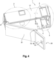
figure 4 illustre un module selon l'invention muni d'un volet spécifique.
- there
figure 1 , already described, illustrates an optical connection module of the state of the art, - there
figure 2 is a front view of an optical connection module according to the invention, - there
picture 3 - there
figure 4 illustrates a module according to the invention provided with a specific flap.
Tel qu'illustré à la
Le module 1 peut être un module d'utilisateurs ou un module d'opérateurs. Le module d'utilisateurs et les modules d'opérateurs sont destinés à être empilés verticalement les uns au-dessus des autres. L'empilement des zones de raccordement 3 forme une cheminée de câblage dans laquelle transitent les cordons de raccordement ou jarretières reliant chacun un module d'opérateur au module d'utilisateurs.
Le module 1 est illustré en configuration opérationnelle, le module 1 étant disposé horizontalement dans le sens de la longueur. La zone de câblage 3, destinée au passage des jarretières à travers les différents modules, comprend deux ouvertures 4 de câblage disposées dans la face inférieure 12 et dans la face supérieure 13 respectivement, et qui forment une cheminée de câblage verticale.
Les connecteurs 21 du module 1 sont disposés sur une paroi verticale 16 qui est parallèle à la face avant et à la face arrière 11, de sorte que les connecteurs 21 font face à l'utilisateur. Contrairement au module de l'état de la technique illustré à la
Tel qu'illustré à la
Le module 1 comprend en outre des zones 10 de gestion des surlongueurs des fibres. Les zones de gestion peuvent être des bacs 10 clipsables, disposés par exemple dans la zone de raccordement 2, et notamment en partie inférieure.The
Le module 1 peut être un module d'utilisateurs ou un module d'opérateurs. Le module d'utilisateurs et les modules d'opérateurs sont destinés à être empilés verticalement les uns au-dessus des autres. L'empilement des zones de raccordement 3 forme une cheminée de câblage dans laquelle transitent les jarretières reliant chacune un module d'opérateur au module d'utilisateurs.
Tel qu'illustré à la
Le volet 20, qui est représenté à la
La présence du volet 20 apporte ainsi de nombreux avantages par rapport au module de l'état de la technique illustré à la
Claims (8)
- An optical connection module (1), of parallelepipedal shape, comprising a module body (17) containing:- a coupling area (2) provided with connectors (21) making it possible to connect optical fibers coming from a set of optical fibers with coupling cords intended to link said module (1) to other optical connection modules, and- a passage area (3) of said cords, allowing a vertical passage of the cords through the module (1),the module comprising a front face for access to the module, a back face joined to the front face by a lower face, an upper face and two side faces, characterized in that the coupling area (2) and the passage area (3) are two separate areas and are horizontally aligned, the connectors (21) being arranged in a same vertical plane (16), said plane (16) being parallel to the direction of alignment of the coupling area (2) and the passage area (3), such that a user can access the connectors (21) directly without passing through the passage area (3), in that the connectors (21) are arranged in a plane (16) parallel to the front face, and in that the connectors (21) comprise couplers (9) with an elongate shape and the longitudinal axis of which is inclined relative to said plane (16), and in that the module (1) further comprises at least one area (10) for managing excess optical fiber lengths.
- The module (1) according to claim 1, characterized in that the incline angle between the couplers (9) and said plane (16) is between 40 and 50°.
- The module (1) according to one of the preceding claims, characterized in that the passage area (3) comprises an opening (4) formed in the lower face and an opening (4) formed in the upper face.
- The module according to claim 1, 2 or 3, characterized in that said at least one area (10) for managing excess optical fiber lengths is a tray (10) that is able to be clipped and is arranged in the lower part of the coupling area (2).
- A modular optical connection device, characterized in that it comprises a plurality of modules (1) according to one of claims 1 to 4, the modules (1) being stacked vertically one above the other, such that the stack of passage areas (3) forms a vertical conduit for the passage of cords.
- The device according to claim 5, characterized in that it comprises coupling cords, intended to connect the connectors (21) of different modules to one another, the coupling cords passing in the vertical passage conduit.
- The device according to claim 5 or 6, characterized in that it comprises a user module and several operator modules.
- The device according to claim 7, characterized in that the user module is arranged at the upper end of the device.
Applications Claiming Priority (3)
| Application Number | Priority Date | Filing Date | Title |
|---|---|---|---|
| FR1350261A FR3001045B1 (en) | 2013-01-11 | 2013-01-11 | OPTICAL CONNECTION MODULE |
| FR1350260A FR3001044B1 (en) | 2013-01-11 | 2013-01-11 | OPTICAL CONNECTION MODULE |
| EP13198702.6A EP2755071B3 (en) | 2013-01-11 | 2013-12-20 | Optical connection module |
Related Parent Applications (2)
| Application Number | Title | Priority Date | Filing Date |
|---|---|---|---|
| EP13198702.6A Division EP2755071B3 (en) | 2013-01-11 | 2013-12-20 | Optical connection module |
| EP13198702.6A Division-Into EP2755071B3 (en) | 2013-01-11 | 2013-12-20 | Optical connection module |
Publications (3)
| Publication Number | Publication Date |
|---|---|
| EP3301491A1 EP3301491A1 (en) | 2018-04-04 |
| EP3301491B1 EP3301491B1 (en) | 2019-12-04 |
| EP3301491B3 true EP3301491B3 (en) | 2023-06-21 |
Family
ID=49767034
Family Applications (2)
| Application Number | Title | Priority Date | Filing Date |
|---|---|---|---|
| EP13198702.6A Active EP2755071B3 (en) | 2013-01-11 | 2013-12-20 | Optical connection module |
| EP17195771.5A Active EP3301491B3 (en) | 2013-01-11 | 2013-12-20 | Optical connection module |
Family Applications Before (1)
| Application Number | Title | Priority Date | Filing Date |
|---|---|---|---|
| EP13198702.6A Active EP2755071B3 (en) | 2013-01-11 | 2013-12-20 | Optical connection module |
Country Status (2)
| Country | Link |
|---|---|
| EP (2) | EP2755071B3 (en) |
| ES (1) | ES2771256T7 (en) |
Families Citing this family (1)
| Publication number | Priority date | Publication date | Assignee | Title |
|---|---|---|---|---|
| CN109599810B (en) * | 2019-02-25 | 2021-03-09 | 中国农业银行股份有限公司 | Pre-wiring device for IT equipment of machine room |
Family Cites Families (7)
| Publication number | Priority date | Publication date | Assignee | Title |
|---|---|---|---|---|
| US4949376A (en) * | 1989-06-15 | 1990-08-14 | Keptel, Inc. | Telephone network interface apparatus |
| US5708751A (en) * | 1996-04-24 | 1998-01-13 | Tii Industries, Inc. | Optical fiber enclosure system |
| US5737475A (en) * | 1997-01-17 | 1998-04-07 | Leviton Manufacturing Co., Inc. | Universal multimedia connection unit |
| US6631237B2 (en) * | 2001-03-06 | 2003-10-07 | Adc Telecommunications, Inc. | Termination and splice panel |
| US6832035B1 (en) * | 2003-05-30 | 2004-12-14 | Lucent Technologies Inc. | Optical fiber connection system |
| DK2191315T3 (en) * | 2007-09-06 | 2015-03-23 | Prysmian Spa | Modular system and methods for connecting an external communication network to a user network |
| US9547145B2 (en) * | 2010-10-19 | 2017-01-17 | Corning Optical Communications LLC | Local convergence point for multiple dwelling unit fiber optic distribution network |
-
2013
- 2013-12-20 EP EP13198702.6A patent/EP2755071B3/en active Active
- 2013-12-20 ES ES17195771T patent/ES2771256T7/en active Active
- 2013-12-20 EP EP17195771.5A patent/EP3301491B3/en active Active
Also Published As
| Publication number | Publication date |
|---|---|
| ES2771256T7 (en) | 2023-11-08 |
| EP3301491A1 (en) | 2018-04-04 |
| EP2755071A1 (en) | 2014-07-16 |
| EP3301491B1 (en) | 2019-12-04 |
| EP2755071B1 (en) | 2018-07-11 |
| ES2771256T3 (en) | 2020-07-06 |
| EP2755071B3 (en) | 2023-08-16 |
Similar Documents
| Publication | Publication Date | Title |
|---|---|---|
| FR2590371A1 (en) | OPTICAL CABLES HEAD CHASSIS | |
| EP1315009B1 (en) | Optical fibre connection and distribution module for an optical crossconnect system | |
| US20090163043A1 (en) | Patch panel with angled module | |
| FR2836561A1 (en) | Flat fibre optic coil winding cassette having modular cassette with base module/input winding passage and second winder with additional module and second winder having connection between winders | |
| EP2463697B1 (en) | Cassette for coiling fibres and maintaining splices | |
| EP3301491B3 (en) | Optical connection module | |
| EP1418769A1 (en) | Telecommunication distributor | |
| WO2002006879A1 (en) | Box for connecting optical fibres to workstations, for buildings | |
| EP0886158A1 (en) | Distribution frame with high density and high capacity, in particular for optical fibres | |
| EP0660477B1 (en) | Wall connection and termination device for an optical cable building distribution system | |
| FR3001045A1 (en) | Parallelepiped optical connection module for use in modular optical connection device in e.g. fiber to home network, has connectors arranged on vertical wall parallel to alignment direction of zones, so that user directly access connectors | |
| FR2559277A1 (en) | Connection box for fibre-optic cables | |
| FR3001044A1 (en) | Parallelepiped optical connection module for use in modular optical connection device in e.g. fiber to home network, has connectors arranged on vertical wall parallel to alignment direction of zones, so that user directly access connectors | |
| FR2923618A1 (en) | OPTICAL OUTLET FOR TELECOMMUNICATION NETWORK | |
| EP1583192B1 (en) | Electric cabinet with cable feedthroughs | |
| EP2618194B1 (en) | Modular connection device | |
| EP3739369A1 (en) | Optical junction or distribution box and fiber routing insert | |
| EP2538255B1 (en) | Cable coupling device with overlength storage for jumper cables | |
| EP3351010B1 (en) | Device for guiding orientable cables | |
| FR2853150A1 (en) | Closing device for raceway of electrical cable housing, has connecting section of covering part enabling movement of secondary fixing units on device to take different functioning positions for coupling with primary fixing units | |
| FR3129495A1 (en) | High Density Optical Splitter | |
| NL1039467C2 (en) | PANEL. | |
| EP2536260B1 (en) | Gateway between a local network and a wide area network | |
| FR3025613A1 (en) | OPTICAL INTERNAL TERMINATION DEVICE AND ASSOCIATED ASSEMBLY | |
| EP3709063A1 (en) | Locking element for an optical connection box |
Legal Events
| Date | Code | Title | Description |
|---|---|---|---|
| PUAI | Public reference made under article 153(3) epc to a published international application that has entered the european phase |
Free format text: ORIGINAL CODE: 0009012 |
|
| STAA | Information on the status of an ep patent application or granted ep patent |
Free format text: STATUS: THE APPLICATION HAS BEEN PUBLISHED |
|
| AC | Divisional application: reference to earlier application |
Ref document number: 2755071 Country of ref document: EP Kind code of ref document: P |
|
| AK | Designated contracting states |
Kind code of ref document: A1 Designated state(s): AL AT BE BG CH CY CZ DE DK EE ES FI FR GB GR HR HU IE IS IT LI LT LU LV MC MK MT NL NO PL PT RO RS SE SI SK SM TR |
|
| STAA | Information on the status of an ep patent application or granted ep patent |
Free format text: STATUS: REQUEST FOR EXAMINATION WAS MADE |
|
| 17P | Request for examination filed |
Effective date: 20181004 |
|
| RBV | Designated contracting states (corrected) |
Designated state(s): AL AT BE BG CH CY CZ DE DK EE ES FI FR GB GR HR HU IE IS IT LI LT LU LV MC MK MT NL NO PL PT RO RS SE SI SK SM TR |
|
| STAA | Information on the status of an ep patent application or granted ep patent |
Free format text: STATUS: EXAMINATION IS IN PROGRESS |
|
| 17Q | First examination report despatched |
Effective date: 20190222 |
|
| GRAP | Despatch of communication of intention to grant a patent |
Free format text: ORIGINAL CODE: EPIDOSNIGR1 |
|
| STAA | Information on the status of an ep patent application or granted ep patent |
Free format text: STATUS: GRANT OF PATENT IS INTENDED |
|
| RIC1 | Information provided on ipc code assigned before grant |
Ipc: G02B 6/44 20060101AFI20190625BHEP Ipc: G02B 6/38 20060101ALN20190625BHEP |
|
| RIC1 | Information provided on ipc code assigned before grant |
Ipc: G02B 6/38 20060101ALN20190628BHEP Ipc: G02B 6/44 20060101AFI20190628BHEP |
|
| INTG | Intention to grant announced |
Effective date: 20190718 |
|
| RIN1 | Information on inventor provided before grant (corrected) |
Inventor name: MONATLIK, JEAN-CHRISTOPHE Inventor name: TRONCONI, GIOVANNI Inventor name: AMROUNI, HAMID Inventor name: APERE, RODOLPHE |
|
| GRAS | Grant fee paid |
Free format text: ORIGINAL CODE: EPIDOSNIGR3 |
|
| GRAA | (expected) grant |
Free format text: ORIGINAL CODE: 0009210 |
|
| STAA | Information on the status of an ep patent application or granted ep patent |
Free format text: STATUS: THE PATENT HAS BEEN GRANTED |
|
| AC | Divisional application: reference to earlier application |
Ref document number: 2755071 Country of ref document: EP Kind code of ref document: P |
|
| AK | Designated contracting states |
Kind code of ref document: B1 Designated state(s): AL AT BE BG CH CY CZ DE DK EE ES FI FR GB GR HR HU IE IS IT LI LT LU LV MC MK MT NL NO PL PT RO RS SE SI SK SM TR |
|
| REG | Reference to a national code |
Ref country code: GB Ref legal event code: FG4D Free format text: NOT ENGLISH |
|
| REG | Reference to a national code |
Ref country code: CH Ref legal event code: EP |
|
| REG | Reference to a national code |
Ref country code: AT Ref legal event code: REF Ref document number: 1210102 Country of ref document: AT Kind code of ref document: T Effective date: 20191215 |
|
| REG | Reference to a national code |
Ref country code: DE Ref legal event code: R096 Ref document number: 602013063787 Country of ref document: DE |
|
| REG | Reference to a national code |
Ref country code: IE Ref legal event code: FG4D Free format text: LANGUAGE OF EP DOCUMENT: FRENCH |
|
| REG | Reference to a national code |
Ref country code: SE Ref legal event code: TRGR |
|
| REG | Reference to a national code |
Ref country code: NL Ref legal event code: MP Effective date: 20191204 |
|
| REG | Reference to a national code |
Ref country code: LT Ref legal event code: MG4D |
|
| PG25 | Lapsed in a contracting state [announced via postgrant information from national office to epo] |
Ref country code: FI Free format text: LAPSE BECAUSE OF FAILURE TO SUBMIT A TRANSLATION OF THE DESCRIPTION OR TO PAY THE FEE WITHIN THE PRESCRIBED TIME-LIMIT Effective date: 20191204 Ref country code: NO Free format text: LAPSE BECAUSE OF FAILURE TO SUBMIT A TRANSLATION OF THE DESCRIPTION OR TO PAY THE FEE WITHIN THE PRESCRIBED TIME-LIMIT Effective date: 20200304 Ref country code: GR Free format text: LAPSE BECAUSE OF FAILURE TO SUBMIT A TRANSLATION OF THE DESCRIPTION OR TO PAY THE FEE WITHIN THE PRESCRIBED TIME-LIMIT Effective date: 20200305 Ref country code: LT Free format text: LAPSE BECAUSE OF FAILURE TO SUBMIT A TRANSLATION OF THE DESCRIPTION OR TO PAY THE FEE WITHIN THE PRESCRIBED TIME-LIMIT Effective date: 20191204 Ref country code: LV Free format text: LAPSE BECAUSE OF FAILURE TO SUBMIT A TRANSLATION OF THE DESCRIPTION OR TO PAY THE FEE WITHIN THE PRESCRIBED TIME-LIMIT Effective date: 20191204 Ref country code: BG Free format text: LAPSE BECAUSE OF FAILURE TO SUBMIT A TRANSLATION OF THE DESCRIPTION OR TO PAY THE FEE WITHIN THE PRESCRIBED TIME-LIMIT Effective date: 20200304 |
|
| PG25 | Lapsed in a contracting state [announced via postgrant information from national office to epo] |
Ref country code: HR Free format text: LAPSE BECAUSE OF FAILURE TO SUBMIT A TRANSLATION OF THE DESCRIPTION OR TO PAY THE FEE WITHIN THE PRESCRIBED TIME-LIMIT Effective date: 20191204 Ref country code: RS Free format text: LAPSE BECAUSE OF FAILURE TO SUBMIT A TRANSLATION OF THE DESCRIPTION OR TO PAY THE FEE WITHIN THE PRESCRIBED TIME-LIMIT Effective date: 20191204 |
|
| PG25 | Lapsed in a contracting state [announced via postgrant information from national office to epo] |
Ref country code: AL Free format text: LAPSE BECAUSE OF FAILURE TO SUBMIT A TRANSLATION OF THE DESCRIPTION OR TO PAY THE FEE WITHIN THE PRESCRIBED TIME-LIMIT Effective date: 20191204 |
|
| REG | Reference to a national code |
Ref country code: DE Ref legal event code: R119 Ref document number: 602013063787 Country of ref document: DE |
|
| REG | Reference to a national code |
Ref country code: ES Ref legal event code: FG2A Ref document number: 2771256 Country of ref document: ES Kind code of ref document: T3 Effective date: 20200706 |
|
| PG25 | Lapsed in a contracting state [announced via postgrant information from national office to epo] |
Ref country code: NL Free format text: LAPSE BECAUSE OF FAILURE TO SUBMIT A TRANSLATION OF THE DESCRIPTION OR TO PAY THE FEE WITHIN THE PRESCRIBED TIME-LIMIT Effective date: 20191204 Ref country code: EE Free format text: LAPSE BECAUSE OF FAILURE TO SUBMIT A TRANSLATION OF THE DESCRIPTION OR TO PAY THE FEE WITHIN THE PRESCRIBED TIME-LIMIT Effective date: 20191204 Ref country code: PT Free format text: LAPSE BECAUSE OF FAILURE TO SUBMIT A TRANSLATION OF THE DESCRIPTION OR TO PAY THE FEE WITHIN THE PRESCRIBED TIME-LIMIT Effective date: 20200429 Ref country code: CZ Free format text: LAPSE BECAUSE OF FAILURE TO SUBMIT A TRANSLATION OF THE DESCRIPTION OR TO PAY THE FEE WITHIN THE PRESCRIBED TIME-LIMIT Effective date: 20191204 Ref country code: RO Free format text: LAPSE BECAUSE OF FAILURE TO SUBMIT A TRANSLATION OF THE DESCRIPTION OR TO PAY THE FEE WITHIN THE PRESCRIBED TIME-LIMIT Effective date: 20191204 |
|
| REG | Reference to a national code |
Ref country code: CH Ref legal event code: PL |
|
| REG | Reference to a national code |
Ref country code: BE Ref legal event code: MM Effective date: 20191231 |
|
| PG25 | Lapsed in a contracting state [announced via postgrant information from national office to epo] |
Ref country code: SM Free format text: LAPSE BECAUSE OF FAILURE TO SUBMIT A TRANSLATION OF THE DESCRIPTION OR TO PAY THE FEE WITHIN THE PRESCRIBED TIME-LIMIT Effective date: 20191204 Ref country code: SK Free format text: LAPSE BECAUSE OF FAILURE TO SUBMIT A TRANSLATION OF THE DESCRIPTION OR TO PAY THE FEE WITHIN THE PRESCRIBED TIME-LIMIT Effective date: 20191204 Ref country code: IS Free format text: LAPSE BECAUSE OF FAILURE TO SUBMIT A TRANSLATION OF THE DESCRIPTION OR TO PAY THE FEE WITHIN THE PRESCRIBED TIME-LIMIT Effective date: 20200404 |
|
| PGFP | Annual fee paid to national office [announced via postgrant information from national office to epo] |
Ref country code: SE Payment date: 20191230 Year of fee payment: 7 |
|
| REG | Reference to a national code |
Ref country code: DE Ref legal event code: R097 Ref document number: 602013063787 Country of ref document: DE |
|
| REG | Reference to a national code |
Ref country code: AT Ref legal event code: MK05 Ref document number: 1210102 Country of ref document: AT Kind code of ref document: T Effective date: 20191204 |
|
| PG25 | Lapsed in a contracting state [announced via postgrant information from national office to epo] |
Ref country code: MC Free format text: LAPSE BECAUSE OF FAILURE TO SUBMIT A TRANSLATION OF THE DESCRIPTION OR TO PAY THE FEE WITHIN THE PRESCRIBED TIME-LIMIT Effective date: 20191204 |
|
| PLBE | No opposition filed within time limit |
Free format text: ORIGINAL CODE: 0009261 |
|
| STAA | Information on the status of an ep patent application or granted ep patent |
Free format text: STATUS: NO OPPOSITION FILED WITHIN TIME LIMIT |
|
| PG25 | Lapsed in a contracting state [announced via postgrant information from national office to epo] |
Ref country code: IE Free format text: LAPSE BECAUSE OF NON-PAYMENT OF DUE FEES Effective date: 20191220 Ref country code: DE Free format text: LAPSE BECAUSE OF NON-PAYMENT OF DUE FEES Effective date: 20200701 Ref country code: DK Free format text: LAPSE BECAUSE OF FAILURE TO SUBMIT A TRANSLATION OF THE DESCRIPTION OR TO PAY THE FEE WITHIN THE PRESCRIBED TIME-LIMIT Effective date: 20191204 Ref country code: LU Free format text: LAPSE BECAUSE OF NON-PAYMENT OF DUE FEES Effective date: 20191220 |
|
| 26N | No opposition filed |
Effective date: 20200907 |
|
| PG25 | Lapsed in a contracting state [announced via postgrant information from national office to epo] |
Ref country code: LI Free format text: LAPSE BECAUSE OF NON-PAYMENT OF DUE FEES Effective date: 20191231 Ref country code: PL Free format text: LAPSE BECAUSE OF FAILURE TO SUBMIT A TRANSLATION OF THE DESCRIPTION OR TO PAY THE FEE WITHIN THE PRESCRIBED TIME-LIMIT Effective date: 20191204 Ref country code: CH Free format text: LAPSE BECAUSE OF NON-PAYMENT OF DUE FEES Effective date: 20191231 Ref country code: SI Free format text: LAPSE BECAUSE OF FAILURE TO SUBMIT A TRANSLATION OF THE DESCRIPTION OR TO PAY THE FEE WITHIN THE PRESCRIBED TIME-LIMIT Effective date: 20191204 Ref country code: AT Free format text: LAPSE BECAUSE OF FAILURE TO SUBMIT A TRANSLATION OF THE DESCRIPTION OR TO PAY THE FEE WITHIN THE PRESCRIBED TIME-LIMIT Effective date: 20191204 Ref country code: BE Free format text: LAPSE BECAUSE OF NON-PAYMENT OF DUE FEES Effective date: 20191231 |
|
| PG25 | Lapsed in a contracting state [announced via postgrant information from national office to epo] |
Ref country code: IT Free format text: LAPSE BECAUSE OF FAILURE TO SUBMIT A TRANSLATION OF THE DESCRIPTION OR TO PAY THE FEE WITHIN THE PRESCRIBED TIME-LIMIT Effective date: 20191204 |
|
| GBPC | Gb: european patent ceased through non-payment of renewal fee |
Effective date: 20200304 |
|
| PG25 | Lapsed in a contracting state [announced via postgrant information from national office to epo] |
Ref country code: GB Free format text: LAPSE BECAUSE OF NON-PAYMENT OF DUE FEES Effective date: 20200304 |
|
| PG25 | Lapsed in a contracting state [announced via postgrant information from national office to epo] |
Ref country code: CY Free format text: LAPSE BECAUSE OF FAILURE TO SUBMIT A TRANSLATION OF THE DESCRIPTION OR TO PAY THE FEE WITHIN THE PRESCRIBED TIME-LIMIT Effective date: 20191204 |
|
| PG25 | Lapsed in a contracting state [announced via postgrant information from national office to epo] |
Ref country code: HU Free format text: LAPSE BECAUSE OF FAILURE TO SUBMIT A TRANSLATION OF THE DESCRIPTION OR TO PAY THE FEE WITHIN THE PRESCRIBED TIME-LIMIT; INVALID AB INITIO Effective date: 20131220 Ref country code: MT Free format text: LAPSE BECAUSE OF FAILURE TO SUBMIT A TRANSLATION OF THE DESCRIPTION OR TO PAY THE FEE WITHIN THE PRESCRIBED TIME-LIMIT Effective date: 20191204 |
|
| REG | Reference to a national code |
Ref country code: SE Ref legal event code: EUG |
|
| PG25 | Lapsed in a contracting state [announced via postgrant information from national office to epo] |
Ref country code: SE Free format text: LAPSE BECAUSE OF NON-PAYMENT OF DUE FEES Effective date: 20201221 |
|
| PG25 | Lapsed in a contracting state [announced via postgrant information from national office to epo] |
Ref country code: TR Free format text: LAPSE BECAUSE OF FAILURE TO SUBMIT A TRANSLATION OF THE DESCRIPTION OR TO PAY THE FEE WITHIN THE PRESCRIBED TIME-LIMIT Effective date: 20191204 |
|
| PG25 | Lapsed in a contracting state [announced via postgrant information from national office to epo] |
Ref country code: MK Free format text: LAPSE BECAUSE OF FAILURE TO SUBMIT A TRANSLATION OF THE DESCRIPTION OR TO PAY THE FEE WITHIN THE PRESCRIBED TIME-LIMIT Effective date: 20191204 |
|
| REG | Reference to a national code |
Ref country code: DE Ref legal event code: R055 Ref document number: 602013063787 Country of ref document: DE |
|
| PLCP | Request for limitation filed |
Free format text: ORIGINAL CODE: EPIDOSNLIM1 |
|
| PLCQ | Request for limitation of patent found admissible |
Free format text: ORIGINAL CODE: 0009231 |
|
| LIM1 | Request for limitation found admissible |
Free format text: SEQUENCE NO: 1; FILED AFTER OPPOSITION PERIOD Filing date: 20221014 Effective date: 20221014 |
|
| PLCO | Limitation procedure: reply received to communication from examining division + time limit |
Free format text: ORIGINAL CODE: EPIDOSNLIR3 |
|
| PLCR | Communication despatched that request for limitation of patent was allowed |
Free format text: ORIGINAL CODE: 0009245 |
|
| REG | Reference to a national code |
Ref country code: DE Ref legal event code: R056 Ref document number: 602013063787 Country of ref document: DE |
|
| PGFP | Annual fee paid to national office [announced via postgrant information from national office to epo] |
Ref country code: ES Payment date: 20230228 Year of fee payment: 10 |
|
| PLCN | Payment of fee for limitation of patent |
Free format text: ORIGINAL CODE: EPIDOSNRAL3 |
|
| PUAM | (expected) publication of b3 document |
Free format text: ORIGINAL CODE: 0009410 |
|
| STAA | Information on the status of an ep patent application or granted ep patent |
Free format text: STATUS: THE PATENT HAS BEEN LIMITED |
|
| P01 | Opt-out of the competence of the unified patent court (upc) registered |
Effective date: 20230529 |
|
| PGFP | Annual fee paid to national office [announced via postgrant information from national office to epo] |
Ref country code: FR Payment date: 20231222 Year of fee payment: 11 |
|
| PGFP | Annual fee paid to national office [announced via postgrant information from national office to epo] |
Ref country code: ES Payment date: 20240129 Year of fee payment: 11 |