EP3301456B1 - Mounting a laser transceiver to an aircraft - Google Patents
Mounting a laser transceiver to an aircraft Download PDFInfo
- Publication number
- EP3301456B1 EP3301456B1 EP17191994.7A EP17191994A EP3301456B1 EP 3301456 B1 EP3301456 B1 EP 3301456B1 EP 17191994 A EP17191994 A EP 17191994A EP 3301456 B1 EP3301456 B1 EP 3301456B1
- Authority
- EP
- European Patent Office
- Prior art keywords
- aircraft
- laser transceiver
- probe
- laser
- angle
- Prior art date
- Legal status (The legal status is an assumption and is not a legal conclusion. Google has not performed a legal analysis and makes no representation as to the accuracy of the status listed.)
- Active
Links
- 239000000523 sample Substances 0.000 claims description 64
- 238000000034 method Methods 0.000 claims description 27
- 230000003068 static effect Effects 0.000 claims description 13
- 239000000835 fiber Substances 0.000 description 12
- 238000005259 measurement Methods 0.000 description 9
- 238000010586 diagram Methods 0.000 description 4
- 238000001514 detection method Methods 0.000 description 2
- 230000003993 interaction Effects 0.000 description 2
- 239000002245 particle Substances 0.000 description 2
- 230000008569 process Effects 0.000 description 2
- 230000008878 coupling Effects 0.000 description 1
- 238000010168 coupling process Methods 0.000 description 1
- 238000005859 coupling reaction Methods 0.000 description 1
- 230000006870 function Effects 0.000 description 1
- 230000006872 improvement Effects 0.000 description 1
- 238000013507 mapping Methods 0.000 description 1
- 230000003287 optical effect Effects 0.000 description 1
Images


Classifications
-
- G—PHYSICS
- G01—MEASURING; TESTING
- G01S—RADIO DIRECTION-FINDING; RADIO NAVIGATION; DETERMINING DISTANCE OR VELOCITY BY USE OF RADIO WAVES; LOCATING OR PRESENCE-DETECTING BY USE OF THE REFLECTION OR RERADIATION OF RADIO WAVES; ANALOGOUS ARRANGEMENTS USING OTHER WAVES
- G01S17/00—Systems using the reflection or reradiation of electromagnetic waves other than radio waves, e.g. lidar systems
- G01S17/88—Lidar systems specially adapted for specific applications
- G01S17/93—Lidar systems specially adapted for specific applications for anti-collision purposes
- G01S17/933—Lidar systems specially adapted for specific applications for anti-collision purposes of aircraft or spacecraft
-
- B—PERFORMING OPERATIONS; TRANSPORTING
- B64—AIRCRAFT; AVIATION; COSMONAUTICS
- B64D—EQUIPMENT FOR FITTING IN OR TO AIRCRAFT; FLIGHT SUITS; PARACHUTES; ARRANGEMENTS OR MOUNTING OF POWER PLANTS OR PROPULSION TRANSMISSIONS IN AIRCRAFT
- B64D47/00—Equipment not otherwise provided for
-
- B—PERFORMING OPERATIONS; TRANSPORTING
- B64—AIRCRAFT; AVIATION; COSMONAUTICS
- B64D—EQUIPMENT FOR FITTING IN OR TO AIRCRAFT; FLIGHT SUITS; PARACHUTES; ARRANGEMENTS OR MOUNTING OF POWER PLANTS OR PROPULSION TRANSMISSIONS IN AIRCRAFT
- B64D15/00—De-icing or preventing icing on exterior surfaces of aircraft
- B64D15/20—Means for detecting icing or initiating de-icing
-
- B—PERFORMING OPERATIONS; TRANSPORTING
- B64—AIRCRAFT; AVIATION; COSMONAUTICS
- B64D—EQUIPMENT FOR FITTING IN OR TO AIRCRAFT; FLIGHT SUITS; PARACHUTES; ARRANGEMENTS OR MOUNTING OF POWER PLANTS OR PROPULSION TRANSMISSIONS IN AIRCRAFT
- B64D43/00—Arrangements or adaptations of instruments
- B64D43/02—Arrangements or adaptations of instruments for indicating aircraft speed or stalling conditions
-
- G—PHYSICS
- G01—MEASURING; TESTING
- G01C—MEASURING DISTANCES, LEVELS OR BEARINGS; SURVEYING; NAVIGATION; GYROSCOPIC INSTRUMENTS; PHOTOGRAMMETRY OR VIDEOGRAMMETRY
- G01C23/00—Combined instruments indicating more than one navigational value, e.g. for aircraft; Combined measuring devices for measuring two or more variables of movement, e.g. distance, speed or acceleration
-
- G—PHYSICS
- G01—MEASURING; TESTING
- G01D—MEASURING NOT SPECIALLY ADAPTED FOR A SPECIFIC VARIABLE; ARRANGEMENTS FOR MEASURING TWO OR MORE VARIABLES NOT COVERED IN A SINGLE OTHER SUBCLASS; TARIFF METERING APPARATUS; MEASURING OR TESTING NOT OTHERWISE PROVIDED FOR
- G01D21/00—Measuring or testing not otherwise provided for
- G01D21/02—Measuring two or more variables by means not covered by a single other subclass
-
- G—PHYSICS
- G01—MEASURING; TESTING
- G01P—MEASURING LINEAR OR ANGULAR SPEED, ACCELERATION, DECELERATION, OR SHOCK; INDICATING PRESENCE, ABSENCE, OR DIRECTION, OF MOVEMENT
- G01P13/00—Indicating or recording presence, absence, or direction, of movement
- G01P13/02—Indicating direction only, e.g. by weather vane
- G01P13/025—Indicating direction only, e.g. by weather vane indicating air data, i.e. flight variables of an aircraft, e.g. angle of attack, side slip, shear, yaw
-
- G—PHYSICS
- G01—MEASURING; TESTING
- G01P—MEASURING LINEAR OR ANGULAR SPEED, ACCELERATION, DECELERATION, OR SHOCK; INDICATING PRESENCE, ABSENCE, OR DIRECTION, OF MOVEMENT
- G01P5/00—Measuring speed of fluids, e.g. of air stream; Measuring speed of bodies relative to fluids, e.g. of ship, of aircraft
- G01P5/26—Measuring speed of fluids, e.g. of air stream; Measuring speed of bodies relative to fluids, e.g. of ship, of aircraft by measuring the direct influence of the streaming fluid on the properties of a detecting optical wave
-
- G—PHYSICS
- G01—MEASURING; TESTING
- G01S—RADIO DIRECTION-FINDING; RADIO NAVIGATION; DETERMINING DISTANCE OR VELOCITY BY USE OF RADIO WAVES; LOCATING OR PRESENCE-DETECTING BY USE OF THE REFLECTION OR RERADIATION OF RADIO WAVES; ANALOGOUS ARRANGEMENTS USING OTHER WAVES
- G01S17/00—Systems using the reflection or reradiation of electromagnetic waves other than radio waves, e.g. lidar systems
- G01S17/02—Systems using the reflection of electromagnetic waves other than radio waves
- G01S17/50—Systems of measurement based on relative movement of target
- G01S17/58—Velocity or trajectory determination systems; Sense-of-movement determination systems
-
- G—PHYSICS
- G01—MEASURING; TESTING
- G01S—RADIO DIRECTION-FINDING; RADIO NAVIGATION; DETERMINING DISTANCE OR VELOCITY BY USE OF RADIO WAVES; LOCATING OR PRESENCE-DETECTING BY USE OF THE REFLECTION OR RERADIATION OF RADIO WAVES; ANALOGOUS ARRANGEMENTS USING OTHER WAVES
- G01S17/00—Systems using the reflection or reradiation of electromagnetic waves other than radio waves, e.g. lidar systems
- G01S17/88—Lidar systems specially adapted for specific applications
- G01S17/95—Lidar systems specially adapted for specific applications for meteorological use
-
- G—PHYSICS
- G01—MEASURING; TESTING
- G01S—RADIO DIRECTION-FINDING; RADIO NAVIGATION; DETERMINING DISTANCE OR VELOCITY BY USE OF RADIO WAVES; LOCATING OR PRESENCE-DETECTING BY USE OF THE REFLECTION OR RERADIATION OF RADIO WAVES; ANALOGOUS ARRANGEMENTS USING OTHER WAVES
- G01S7/00—Details of systems according to groups G01S13/00, G01S15/00, G01S17/00
- G01S7/48—Details of systems according to groups G01S13/00, G01S15/00, G01S17/00 of systems according to group G01S17/00
- G01S7/481—Constructional features, e.g. arrangements of optical elements
- G01S7/4811—Constructional features, e.g. arrangements of optical elements common to transmitter and receiver
- G01S7/4813—Housing arrangements
-
- Y—GENERAL TAGGING OF NEW TECHNOLOGICAL DEVELOPMENTS; GENERAL TAGGING OF CROSS-SECTIONAL TECHNOLOGIES SPANNING OVER SEVERAL SECTIONS OF THE IPC; TECHNICAL SUBJECTS COVERED BY FORMER USPC CROSS-REFERENCE ART COLLECTIONS [XRACs] AND DIGESTS
- Y02—TECHNOLOGIES OR APPLICATIONS FOR MITIGATION OR ADAPTATION AGAINST CLIMATE CHANGE
- Y02A—TECHNOLOGIES FOR ADAPTATION TO CLIMATE CHANGE
- Y02A90/00—Technologies having an indirect contribution to adaptation to climate change
- Y02A90/10—Information and communication technologies [ICT] supporting adaptation to climate change, e.g. for weather forecasting or climate simulation
Definitions
- LIDAR light detecting and ranging
- air data parameters are measured by various probes. For example, angle of airflow is measured by angle of attack vanes, air speed is measured by pitot and/or static ports, and ice detection is measured by ice detector sensors mounted alongside the aircraft. While these probes are placed in optimum locations, there remains a risk of damage to the vanes and errors in the measurement due to external obstacles (such as a bird) hitting the vane protruding from these probes.
- an aircraft has a life of approximately forty years.
- mounting the LIDAR laser transceiver on an existing (older) aircraft often requires fabricating new holes in the aircraft and including additional wiring to connect the aircraft's processing system to the LIDAR laser transceiver.
- US2012/0089362 describes an aircraft with four laser anemometers.
- MANDLE Jaques in “Airborne Lidar System Profiles Wind Fields", Laser Focus World, 4 Jan 1996, describes mounting a laser transceiver to an aircraft using existing holes.
- US2011/0043785 and US2003/0219252 both describe the use of multifunctional LiDAR in aircraft.
- US2011/0141471 describes an optical anemometric probe with two measurement axes
- a method of mounting at least one laser transceiver on an aircraft comprises: determining whether there is a probe located in a desirable position on the aircraft; when a probe is located in a desirable position: removing the located probe such that at least one hole remains in a desirable position, wherein the located probe is selected from the group consisting of an angle of attack vane, a pitot probe, a static port, a pitot static probe, a temperature probe, or an ice detector probe; aligning the at least one laser transceiver with at least one hole that remains after removing the located probe; connecting the at least one laser transceiver to aircraft electronics; and attaching the at least one laser transceiver to the aircraft aligned with the at least one hole; when a probe is not located in a desirable position: fabricating at least one hole in the desirable position; aligning the at least one laser transceiver with the at least one fabricated hole; connecting the at least one laser
- Embodiments of the present disclosure describe systems and methods for mounting at least one laser transceiver to an aircraft.
- the laser transceivers described herein can be used to obtain air data parameters.
- Embodiments of the present disclosure describes mounting laser transceivers in existing aircrafts and/or new aircrafts.
- this laser transceiver may be a Light Detecting and Ranging (LIDAR) laser transceiver.
- LIDAR Light Detecting and Ranging
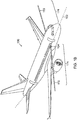
- Figures 1A-1B describe an example mounting configuration for a laser transceiver for an aircraft 100 according to one embodiment of the present disclosure.
- Figure 1A shows a side view of aircraft 100 having a laser transceiver 104 mounted to the aircraft.
- aircraft 100 includes at least one laser transceiver 104 mounted along a waterline 102.
- at least one laser transceiver 104 is a LIDAR laser transceiver.
- a waterline (WL) of an aircraft designates location in the height of the aircraft from ground up.
- laser transceiver is mounted along a waterline 102, wherein waterline 102 runs along a center of fuselage 106 of aircraft 100.
- the center of the fuselage is in the middle (halfway) between bottom 112 of aircraft 100 and top 122 of the aircraft 100.
- FIG 1B shows a perspective view of aircraft 100 having laser transceiver 104 mounted to aircraft 100 at waterline 102.
- laser transceiver 104 is configured to transmit one or more laser beams 110. These laser beams 110 are transmitted in a selected beam region 174. In example embodiments, laser beams 110 are transmitted as far as 10 meters out and beam region 174 is 10 meters away from the outer surface of aircraft 100. The air data parameters measured within beam region 174 are not disturbed by aircraft 100.
- FIG. 1C is a block diagram of example aircraft 100 that has laser transceiver 104 mounted to it.
- these laser beams 110 may be generated in a transceiver head of the laser transceiver 104.
- the laser beams are generated in an avionics bay 160 of aircraft 100.
- the laser transceiver 104 is connected to fiber optic cables 165 and a fiber optic channel is used to send and receive light signals to the laser transceiver 110. These laser beams 110 are then transmitted by laser transceiver 104 for obtaining various measurements.
- the laser transceiver 104 is further configured to measure air data parameters.
- the laser light beams 110 transmitted by laser transceiver 104 interact with particles in a volume of air in a beam region 174 and cause at least a portion of the one or more laser light beams 110 to be reflected back due to backscatter.
- the reflected portion of the laser beam due to this interaction is known as backscatter.
- Laser transceiver 104 includes collection optics that receive the reflection and the backscatter is processed by processor 150.
- Processor 150 is further configured to filter and digitize the backscatter signals into a computational value for air data parameters. These measurements may further be stored in a memory 155 included on aircraft 100.
- laser transceiver 104 is generally configured or tuned to obtain measurements from air that is in a predefined beam region 174 away from aircraft 100.
- This predefined beam region 174 is a volume of air near aircraft 100.
- this predefined beam region 174 can be controlled by adjusting the angle at which the one or more laser light beams 110 are transmitted from the laser transceiver 104. In an example, this angle can be adjusted by adjusting window(s) through which the light beams 110 are transmitted.
- the predefined beam region 174 can be controlled by geometrically adjusting the propagation of the one or more laser light beams 110.
- laser transceiver 104 is mounted to an outer surface of aircraft 100, such as the skin of aircraft 100.
- laser transceiver 104 is flush mounted with the outer surface of aircraft 100 such that the outer edge of laser transceiver 104 is completely aligned with outer surface of aircraft 100. (See Figure 3E ). Flush mounting laser transceiver 104 reduces drag, limits damage and icing potential of laser transceiver 104 when measuring air data parameters.
- FIG 2 shows an example of laser transceiver 104 mounted in various locations.
- laser transceiver 104 is mounted on waterline 102 along the center of the fuselage 106 in a front section of aircraft 100 (104-1), in a middle section of aircraft 100 (104-2), or in a back section of aircraft 100 (104-3).
- laser transceiver is configured to measure at least one of angle of air flow, air speed, angle of sideslip, air temperature, and air pressure. Conventionally, these parameters are measured by multiple probes, each probe configured to measure a respective function. These probes may include an angle of attack vane, a pitot probe, a static port, a pitot static probe, a temperature probe, or an ice detector probe.
- the laser transceiver 104 is mounted in place of at least one of these probes. That is, the laser transceiver 104 is retrofit mounted to aircraft 100.
- angle of air flow in an aircraft is measured by angle of attack vanes that include a mechanical vane that changes direction depending on the angle of the airflow across the vane.
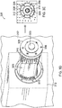
- Figures 3A-3E depict an exemplary process 300 of retrofit mounting a laser transceiver 104 to an aircraft.
- Figure 3A illustrates an angle of attack vane 314 attached to skin 312 of an aircraft.
- Angle of attack vane 314 has a vane 328 that is used to measure the angle of attack in the aircraft.
- the angle of attack vane 314 is attached to skin 312 with screws 318.
- the next step, shown in Figure 3B illustrates that angle of attack vane 314 can be removed by removing screws 318 and sliding the angle of attack vane 314 out of the aircraft. Hole 325 remains after the angle of attack vane 314 has been removed.
- FIG 3C shows a side view of an exemplary laser transceiver 304 to be mounted in hole 325 in place of the angle of attack vane 314 that has been removed.
- laser transceiver 304 is a LIDAR laser transceiver.
- Laser transceiver 304 includes a transceiver head 335 having an outer surface 332 and electrical connectors 345.
- transceiver head 335 generates laser beams transmitted by the laser transceiver 304.
- electrical and/or fiber optic cable connectors 345 connect the laser transceiver to aircraft electronics.
- the electrical and/or fiber optic cable connectors 345 are used to connect the laser transceiver 304 to an avionics bay, e.g., Avionics bay 160 of Figure 1C , in aircraft.
- Laser transceiver 304 is then aligned with hole 325 as illustrated in Figure 3D .
- laser transceiver 304 has the same dimensions as the angle of attack vane 314.
- Laser transceiver 304 can be connected to aircraft electronics via aircraft electrical and/or fiber optic connectors 372.
- Laser transceiver 304 includes a window 320 to transmit laser beam through it.
- Laser transceiver 304 is then attached to the aircraft by inserting laser transceiver 304 in hole 325.
- Figure 3E illustrates a laser transceiver 304 after it is attached to the aircraft.
- laser transceiver 304 is flush mounted to skin 312 so that outer surface 332 of head 335 of laser transceiver 304 is aligned with the outer surface (skin 312) of the aircraft.
- laser transceiver 304 transmits laser beam 310 through window 320.
- Figures 5A and 5B illustrate two different ways of attaching a laser transceiver to an aircraft.
- the example laser transceivers shown in Figures 5A and 5B are LIDAR laser transceivers.
- Figure 5A illustrates an example of attaching laser transceiver 504 to an inner surface 542 of an aircraft 500.
- Aircraft 500 has a hole 525 drilled through it. In the example shown in Figure 5A , hole 525 has dimensions approximately equal to laser head 535 of laser transceiver 504.
- Aircraft 500 also has an inner surface 542 and an outer surface 512.
- the laser transceiver 504 is pushed through hole 525 out to the aircraft and laser transceiver 504 is attached to inner surface 542 of the aircraft 500 using fastening means 538 (such as screws, alignment pins, etc.).
- laser transceiver 504 may be connected (not shown) to aircraft electronics using electrical connectors 548 and/or fiber connectors 545 prior to pushing laser transceiver 504 through hole 525 and attaching it to aircraft 500.
- Figure 5B illustrates an example of attaching laser transceiver 504 to an outer surface 512 of aircraft 500.
- the laser transceiver 504 slides into hole 525 of aircraft 500 and the laser transceiver is attached to the outer surface 512 of the aircraft using fastening means 538 (such as screws, alignment pins, etc.).
- hole 525 can be approximately equal to or bigger than the laser transceiver head 504 so that the laser transceiver 504 can easily slide into hole 525 to connect to aircraft electronics and/or fiber optics.
- laser transceiver 504 is connected to aircraft electronics using electrical connectors 548 and/or fiber optic cable connectors 545 prior to sliding laser transceiver 504 into hole 525.
- Figure 5C illustrates an example of attaching laser transceiver 504 to aircraft 500 by flush mounting laser transceiver 504 to aircraft 500.
- hole 525 includes a recess 528 in aircraft 500 surrounding hole 525.
- laser transceiver 504 slides into recess 525 such that a flange around laser transceiver head 535 is attached to a recess surface 520 and face 540 of laser transceiver 504 is flush with outer surface 512 of aircraft 500.
- the outer surface of the laser transceiver and the outer surface of the aircraft are aligned with each other without any protrusion.
- Laser transceiver 504 is connected to aircraft electronics using electrical connectors 548 and/or fiber optic cable connectors 545.
- laser transceiver 104 may be mounted in the location of an angle of attack vane that has been removed (104-1). Laser transceiver may also replace a pitot tube, static port or an ice detector probe, if such probes are provided (contrary to pitot tube 104-4, static port 104-5 and ice detector probe 104-6 in figure 2 ) on the waterline at the center of the fuselage of the aircraft. In example embodiments, at least two laser transceivers 104 have to be mounted to aircraft 100 to obtain air data parameters with optimum resolution.
- laser transceiver 104 is configured to measure one or more air data parameters including air speed, angle of sideslip, angle of airflow, angle of attack, air temperature, air pressure, density and altitude of the aircraft.
- an existing sensor such as a pitot probe, ice detector, angle of attack vane, etc.
- laser transceiver 104 are configured to measure a respective air data parameter. In such a case, data from both the existing sensor and the laser transceiver 104 are processed by processor 150.
- aircraft 100 may include four angle of attack vanes (two (two on each side of aircraft 100) to accurately measure angle of airflow.
- two laser transceivers 104 retrofitted in a location of angle of attack vanes may be sufficient to accurately measure the angle of airflow.
- two of the four angle of attack vanes may be removed and laser transceiver 104 is mounted in the location of the two angle of attack vanes that have been removed.
- the angle of airflow is measured by laser transceivers 104 and the two remaining angle of attack vanes on aircraft 100 and the data is processed by processor 150.
- Such a hybrid system is especially advantageous because it provides a back up option in a situation where one of the sensors (laser transceiver or angle of attack vane) fails.
- laser transceiver 104 is configured to measure multiple air data parameters and the laser transceiver 104 may be retrofitted in a location of a first respective probe corresponding to first of the multiple air data parameters.
- one or more probes corresponding to remaining of the multiple air data parameters may be removed and the hole that remains in location of one or more removed probes is closed.
- the hole may be closed by flush mounting a non-functional cover to an outer surface of aircraft 100.
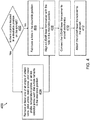
- FIG 4 is a flow diagram showing an exemplary method 400 for mounting at least one laser transceiver, such as laser transceiver 104 to an aircraft, such as aircraft 100.
- laser transceiver such as laser transceiver 104
- mounting laser transceiver on an existing aircraft enables the aircraft to measure air data parameters without having to fabricate additional holes or utilizing additional wiring.
- method 400 is described with respect to examples of aircrafts shown in Figures 1A-3 and Figures 5A-5C . However, method 400 may apply to other examples of aircraft systems as well.
- Method 400 begins at block 402 with determining whether there is a probe located in a desirable position on the aircraft.
- the desirable position is determined by the aircraft manufacturer or system integrator.
- the desirable position is determined to be the location at which the laser transceiver will provide optimum data and/or laser alignment over the course of the flight for the respective air data parameter that the laser transceiver is configured to measure.
- These air data parameters may be one or more of airspeed, Mach number, angle of sideslip, angle of airflow, angle of attack, air temperature, air pressure, density or altitude of the aircraft, and ice detection on the aircraft.
- this desirable position may be along a waterline location of the aircraft, wherein the waterline location is along the center of a fuselage of the aircraft.
- the desirable position is determined based on the dimensions of the laser transceiver to be mounted to the aircraft. In such an example, the location of the probe determined to have dimensions approximately equal to the laser transceiver is determined as the desirable position on the aircraft.
- method 400 proceeds to block 404 with removing at least one of an angle of attack vane, a pitot probe, a static port, a pitot static probe, a temperature probe, or an ice detector probe.
- one or more of the probes removed are at a waterline location, wherein the waterline location is along the center of a fuselage of the aircraft.
- the probe to be removed is attached with screws and alignment pins. In such embodiments, the probe is removed after removing the screws and alignment pins. Once the respective probe is removed a hole, such as hole 325 remains in place of the respective probe.
- method 400 proceeds to block 406 with fabricating at least one hole in a desirable position.
- This desirable position is along a waterline location of the aircraft, wherein the waterline location is along the center of a fuselage of the aircraft.
- method 400 then proceeds to block 408 with aligning the at least one laser transceiver with the at least one hole in the desirable position.
- This hole may be the one that remains after at least one of an angle of attack vane, a pitot probe, a static port, a pitot static probe, a temperature probe or an ice detector probe have been removed or a hole that has been fabricated on the aircraft.
- Laser transceiver is configured to measure at least the air data parameter. When at least one probe has been removed to create a hole in the desirable position, the laser transceiver is configured to measure air data parameter corresponding to the probe that has been removed.
- Laser transceiver may be configured to measure one or more air data parameters including air speed, angle of sideslip, angle of airflow, angle of attack, air temperature, air pressure, density or altitude of the aircraft.
- method 400 then proceeds to block 410 with connecting the laser transceiver to aircraft electronics, such as aircraft electronics 372.
- aircraft electronics such as aircraft electronics 372.
- method 400 proceeds to connecting the laser transceiver to aircraft electronics prior to aligning the at least one laser transceiver with the at least one hole in the desirable position. That is, in exemplary embodiments of this method, step 410 may be performed prior to step 408.
- connecting the laser transceiver to aircraft electronics includes coupling the laser transceiver to fiber optic cables, such as fiber optic cables 165, wherein a fiber optic channel is used to send and receive light signals to the laser transceiver to transmit laser light beams, such as laser light beams 110.
- laser light beams are transmitted by laser transceiver and interact with particles in a volume of air. The interaction causes at least a portion of the one or more laser light beams to be reflected back due to backscatter.
- Laser transceiver 104 receives the reflection and the backscatter is processed by processor 150.
- Processor 150 is configured to filter and digitize the backscatter signals into a computational value for air data parameters. These measurements may further be stored in a memory 155 included on aircraft 100.
- Method 400 then proceeds to block 412 with attaching the laser transceiver to the aircraft aligned with the at least one hole.
- attaching the laser transceiver to the aircraft includes mounting the laser transceiver to an outer surface of the aircraft and attaching the laser transceiver to an outer surface.
- an outer surface mount See Figure 5B
- the laser transceiver slides into the aircraft and the laser transceiver is attached to the outer surface of the aircraft using fastening means (such as screws, alignment pins, etc.).
- attaching the laser transceiver to the aircraft includes mounting the laser transceiver to an inner surface of the aircraft and attaching the laser transceiver to an inner surface.
- the laser transceiver is pushed through the hole out to the aircraft and the laser transceiver is attached to the inner surface of the aircraft using fastening means (such as screws, alignment pins, etc.).
- attaching the laser transceiver to the aircraft include flush mounting the laser transceiver to an outer surface of the aircraft (See Figure 5C ). In such an example, the outer surface of the laser transceiver and the outer surface of the aircraft are aligned with each other without any protrusion.
- attaching the laser transceiver to the aircraft include flush mounting the laser transceiver to the outer surface of the aircraft, such as the skin.
- the outer surface of the laser transceiver and the outer surface of the aircraft are aligned with each other without a protrusion.
- flush mounting laser transceiver to the outer surface of the aircraft reduces the risk of damage to probe vanes or errors caused in the measurements due to obstacles hitting a probe vane. Because the laser light beams transmitted by the laser transceiver propagate for several meters more than the reach of a conventional air data probe, the measurements are less affected by external disturbances.
- method 400 proceeds to aligning the at least one laser transceiver with the at least one hole in the desirable position, attaching the at least one laser transceiver with the at least one hole in the desirable position, and then connecting the laser transceiver to aircraft electronics.
- method 400 proceeds to connecting the laser transceiver to aircraft electronics (410), then aligning the at least one laser transceiver with the at least one hole in the desirable position (408), and then attaching the at least one laser transceiver with the aircraft (412).
- method 400 proceeds to aligning the at least one laser transceiver with the at least one hole in the desirable position (408), the connecting the laser transceiver to aircraft electronics (410), and then attaching the at least one laser transceiver with the aircraft (412).
Description
- Many conventional aerospace systems use light detecting and ranging (LIDAR) laser transceivers to detect range for various applications including aerial mapping, scanning 3D objects surround an aircraft, etc. Further, LIDAR can use lasers for other aerospace applications including measuring air data parameters such as angle of airflow.
- In conventional systems, air data parameters are measured by various probes. For example, angle of airflow is measured by angle of attack vanes, air speed is measured by pitot and/or static ports, and ice detection is measured by ice detector sensors mounted alongside the aircraft. While these probes are placed in optimum locations, there remains a risk of damage to the vanes and errors in the measurement due to external obstacles (such as a bird) hitting the vane protruding from these probes.
- Typically, an aircraft has a life of approximately forty years. However, mounting the LIDAR laser transceiver on an existing (older) aircraft often requires fabricating new holes in the aircraft and including additional wiring to connect the aircraft's processing system to the LIDAR laser transceiver.
- For the reasons stated above and for other reasons stated below which will become apparent to those skilled in the art upon reading and understanding the specification, there is a need in the art for improvement of mounting a LIDAR laser transceiver.
-
US2012/0089362 describes an aircraft with four laser anemometers. MANDLE, Jaques in "Airborne Lidar System Profiles Wind Fields", Laser Focus World, 4 Jan 1996, describes mounting a laser transceiver to an aircraft using existing holes.US2011/0043785 andUS2003/0219252 both describe the use of multifunctional LiDAR in aircraft.US2011/0141471 describes an optical anemometric probe with two measurement axes - The present invention, in its various aspects, is as set out in the appended claims. A method of mounting at least one laser transceiver on an aircraft is provided. The method comprises: determining whether there is a probe located in a desirable position on the aircraft; when a probe is located in a desirable position: removing the located probe such that at least one hole remains in a desirable position, wherein the located probe is selected from the group consisting of an angle of attack vane, a pitot probe, a static port, a pitot static probe, a temperature probe, or an ice detector probe; aligning the at least one laser transceiver with at least one hole that remains after removing the located probe; connecting the at least one laser transceiver to aircraft electronics; and attaching the at least one laser transceiver to the aircraft aligned with the at least one hole; when a probe is not located in a desirable position:
fabricating at least one hole in the desirable position; aligning the at least one laser transceiver with the at least one fabricated hole; connecting the at least one laser transceiver to aircraft electronics; and attaching the laser transceiver to the aircraft aligned with the at least one hole; wherein the at least one laser transceiver is configured to measure at least one air data parameter; and wherein the desirable position is a waterline location of the aircraft, wherein the waterline location is along the center of a fuselage of the aircraft wherein the center is in the middle between the top and the bottom of the fuselage. - Understanding that the drawings depict only exemplary embodiments and are not therefore to be considered limiting in scope, the exemplary embodiments will be described with additional specificity and detail through the use of the accompanying drawings, in which:
-
Figure 1A illustrates a side view of an example aircraft with a laser transceiver mounted. -
Figure 1B illustrates a perspective view of the example aircraft ofFigure 1A . -
Figure 1C is a block diagram of the example aircraft ofFigure 1A . -
Figure 2 illustrates example aircraft with laser transceivers mounted in various locations. -
Figures 3A-3E illustrate an example retrofit process of mounting a laser transceiver to an aircraft. -
Figure 4 is a flow diagram illustrating an exemplary method for mounting a laser transceiver to an aircraft. -
Figures 5A, 5B and5C are side views in partial cross section that illustrate mounting a laser transceiver to the fuselage of an aircraft. - In accordance with common practice, the various described features are not drawn to scale but are drawn to emphasize specific features relevant to the exemplary embodiments.
- In the following detailed description, reference is made to the accompanying drawings that form a part hereof, and in which is shown by way of illustration specific illustrative embodiments. However, it is to be understood that other embodiments may be utilized and that logical, mechanical, and electrical changes may be made. Furthermore, the method presented in the drawing figures and the specification is not to be construed as limiting the order in which the individual steps may be performed. The following detailed description is, therefore, not to be taken in a limiting sense.
- Embodiments of the present disclosure describe systems and methods for mounting at least one laser transceiver to an aircraft. The laser transceivers described herein can be used to obtain air data parameters. Embodiments of the present disclosure describes mounting laser transceivers in existing aircrafts and/or new aircrafts. In example embodiments, this laser transceiver may be a Light Detecting and Ranging (LIDAR) laser transceiver.
-
Figures 1A-1B describe an example mounting configuration for a laser transceiver for anaircraft 100 according to one embodiment of the present disclosure. Specifically,Figure 1A shows a side view ofaircraft 100 having alaser transceiver 104 mounted to the aircraft. As shown inFigure 1A ,aircraft 100 includes at least onelaser transceiver 104 mounted along awaterline 102. In example embodiments, at least onelaser transceiver 104 is a LIDAR laser transceiver. - A waterline (WL) of an aircraft designates location in the height of the aircraft from ground up. In the example shown in
Figure 1 , laser transceiver is mounted along awaterline 102, whereinwaterline 102 runs along a center offuselage 106 ofaircraft 100. In the example shown inFigure 1 , the center of the fuselage is in the middle (halfway) betweenbottom 112 ofaircraft 100 andtop 122 of theaircraft 100. -
Figure 1B shows a perspective view ofaircraft 100 havinglaser transceiver 104 mounted toaircraft 100 atwaterline 102. As shown inFigure 1B ,laser transceiver 104 is configured to transmit one ormore laser beams 110. Theselaser beams 110 are transmitted in aselected beam region 174. In example embodiments,laser beams 110 are transmitted as far as 10 meters out andbeam region 174 is 10 meters away from the outer surface ofaircraft 100. The air data parameters measured withinbeam region 174 are not disturbed byaircraft 100. -
Figure 1C is a block diagram ofexample aircraft 100 that haslaser transceiver 104 mounted to it. In an example, theselaser beams 110 may be generated in a transceiver head of thelaser transceiver 104. In an example, the laser beams are generated in an avionics bay 160 ofaircraft 100. In such an example, thelaser transceiver 104 is connected to fiberoptic cables 165 and a fiber optic channel is used to send and receive light signals to thelaser transceiver 110. Theselaser beams 110 are then transmitted bylaser transceiver 104 for obtaining various measurements. - The
laser transceiver 104 is further configured to measure air data parameters. Thelaser light beams 110 transmitted bylaser transceiver 104 interact with particles in a volume of air in abeam region 174 and cause at least a portion of the one or morelaser light beams 110 to be reflected back due to backscatter. Whenlight beams 110 interact with atoms, molecules, or the like in the volume of air inbeam region 174, the reflected portion of the laser beam due to this interaction is known as backscatter.Laser transceiver 104 includes collection optics that receive the reflection and the backscatter is processed byprocessor 150.Processor 150 is further configured to filter and digitize the backscatter signals into a computational value for air data parameters. These measurements may further be stored in amemory 155 included onaircraft 100. - Referring back to
Figure 1B ,laser transceiver 104 is generally configured or tuned to obtain measurements from air that is in apredefined beam region 174 away fromaircraft 100. Thispredefined beam region 174 is a volume of air nearaircraft 100. In an example, thispredefined beam region 174 can be controlled by adjusting the angle at which the one or morelaser light beams 110 are transmitted from thelaser transceiver 104. In an example, this angle can be adjusted by adjusting window(s) through which thelight beams 110 are transmitted. In an example, thepredefined beam region 174 can be controlled by geometrically adjusting the propagation of the one or morelaser light beams 110. - In one embodiment,
laser transceiver 104 is mounted to an outer surface ofaircraft 100, such as the skin ofaircraft 100. In example embodiments,laser transceiver 104 is flush mounted with the outer surface ofaircraft 100 such that the outer edge oflaser transceiver 104 is completely aligned with outer surface ofaircraft 100. (SeeFigure 3E ). Flush mountinglaser transceiver 104 reduces drag, limits damage and icing potential oflaser transceiver 104 when measuring air data parameters. -
Figure 2 shows an example oflaser transceiver 104 mounted in various locations. According to the invention,laser transceiver 104 is mounted onwaterline 102 along the center of thefuselage 106 in a front section of aircraft 100 (104-1), in a middle section of aircraft 100 (104-2), or in a back section of aircraft 100 (104-3). - In one embodiment, laser transceiver is configured to measure at least one of angle of air flow, air speed, angle of sideslip, air temperature, and air pressure. Conventionally, these parameters are measured by multiple probes, each probe configured to measure a respective function. These probes may include an angle of attack vane, a pitot probe, a static port, a pitot static probe, a temperature probe, or an ice detector probe.
- In one embodiment, the
laser transceiver 104 is mounted in place of at least one of these probes. That is, thelaser transceiver 104 is retrofit mounted toaircraft 100. For example, conventionally, angle of air flow in an aircraft is measured by angle of attack vanes that include a mechanical vane that changes direction depending on the angle of the airflow across the vane.Figures 3A-3E depict anexemplary process 300 of retrofit mounting alaser transceiver 104 to an aircraft.Figure 3A illustrates an angle ofattack vane 314 attached toskin 312 of an aircraft. Angle ofattack vane 314 has avane 328 that is used to measure the angle of attack in the aircraft. Due tovane 328 protruding out, there remains a risk of damage to the vanes and errors in the measurement due to externalobstacles striking vane 328. In exemplary embodiments, the angle ofattack vane 314 is attached toskin 312 withscrews 318. The next step, shown inFigure 3B , illustrates that angle ofattack vane 314 can be removed by removingscrews 318 and sliding the angle ofattack vane 314 out of the aircraft.Hole 325 remains after the angle ofattack vane 314 has been removed. -
Figure 3C shows a side view of anexemplary laser transceiver 304 to be mounted inhole 325 in place of the angle ofattack vane 314 that has been removed. In the example shown inFigures 3C-3E ,laser transceiver 304 is a LIDAR laser transceiver.Laser transceiver 304 includes atransceiver head 335 having anouter surface 332 andelectrical connectors 345. In an example,transceiver head 335 generates laser beams transmitted by thelaser transceiver 304. In an example, electrical and/or fiberoptic cable connectors 345 connect the laser transceiver to aircraft electronics. In an example, the electrical and/or fiberoptic cable connectors 345 are used to connect thelaser transceiver 304 to an avionics bay, e.g.,Avionics bay 160 ofFigure 1C , in aircraft. -
Laser transceiver 304 is then aligned withhole 325 as illustrated inFigure 3D . In the example shown inFigure 3D ,laser transceiver 304 has the same dimensions as the angle ofattack vane 314.Laser transceiver 304 can be connected to aircraft electronics via aircraft electrical and/orfiber optic connectors 372.Laser transceiver 304 includes awindow 320 to transmit laser beam through it. -
Laser transceiver 304 is then attached to the aircraft by insertinglaser transceiver 304 inhole 325.Figure 3E illustrates alaser transceiver 304 after it is attached to the aircraft. In the example shown inFigure 3E ,laser transceiver 304 is flush mounted toskin 312 so thatouter surface 332 ofhead 335 oflaser transceiver 304 is aligned with the outer surface (skin 312) of the aircraft. As shown inFigure 3E , afterlaser transceiver 304 has been connected toaircraft electronics 372 and is attached toaircraft laser transceiver 304,laser transceiver 304 transmitslaser beam 310 throughwindow 320. -
Figures 5A and 5B illustrate two different ways of attaching a laser transceiver to an aircraft. The example laser transceivers shown inFigures 5A and 5B are LIDAR laser transceivers.Figure 5A illustrates an example of attachinglaser transceiver 504 to aninner surface 542 of anaircraft 500.Aircraft 500 has ahole 525 drilled through it. In the example shown inFigure 5A ,hole 525 has dimensions approximately equal tolaser head 535 oflaser transceiver 504.Aircraft 500 also has aninner surface 542 and anouter surface 512. As shown inFigure 5A , thelaser transceiver 504 is pushed throughhole 525 out to the aircraft andlaser transceiver 504 is attached toinner surface 542 of theaircraft 500 using fastening means 538 (such as screws, alignment pins, etc.). In an example,laser transceiver 504 may be connected (not shown) to aircraft electronics usingelectrical connectors 548 and/orfiber connectors 545 prior to pushinglaser transceiver 504 throughhole 525 and attaching it toaircraft 500. -
Figure 5B illustrates an example of attachinglaser transceiver 504 to anouter surface 512 ofaircraft 500. In an example of an outer surface mount, thelaser transceiver 504 slides intohole 525 ofaircraft 500 and the laser transceiver is attached to theouter surface 512 of the aircraft using fastening means 538 (such as screws, alignment pins, etc.). In such an example,hole 525 can be approximately equal to or bigger than thelaser transceiver head 504 so that thelaser transceiver 504 can easily slide intohole 525 to connect to aircraft electronics and/or fiber optics. In an example,laser transceiver 504 is connected to aircraft electronics usingelectrical connectors 548 and/or fiberoptic cable connectors 545 prior to slidinglaser transceiver 504 intohole 525. -
Figure 5C illustrates an example of attachinglaser transceiver 504 toaircraft 500 by flush mountinglaser transceiver 504 toaircraft 500. In the example shown inFigure 5C ,hole 525 includes arecess 528 inaircraft 500 surroundinghole 525. In an example of a flush mount,laser transceiver 504 slides intorecess 525 such that a flange aroundlaser transceiver head 535 is attached to arecess surface 520 and face 540 oflaser transceiver 504 is flush withouter surface 512 ofaircraft 500. In such an example, the outer surface of the laser transceiver and the outer surface of the aircraft are aligned with each other without any protrusion.Laser transceiver 504 is connected to aircraft electronics usingelectrical connectors 548 and/or fiberoptic cable connectors 545. - Referring back to
Figure 2 ,laser transceiver 104 may be mounted in the location of an angle of attack vane that has been removed (104-1). Laser transceiver may also replace a pitot tube, static port or an ice detector probe, if such probes are provided (contrary to pitot tube 104-4, static port 104-5 and ice detector probe 104-6 infigure 2 ) on the waterline at the center of the fuselage of the aircraft. In example embodiments, at least twolaser transceivers 104 have to be mounted toaircraft 100 to obtain air data parameters with optimum resolution. - In exemplary embodiments,
laser transceiver 104 is configured to measure one or more air data parameters including air speed, angle of sideslip, angle of airflow, angle of attack, air temperature, air pressure, density and altitude of the aircraft. In exemplary embodiments, an existing sensor (such as a pitot probe, ice detector, angle of attack vane, etc.) andlaser transceiver 104 are configured to measure a respective air data parameter. In such a case, data from both the existing sensor and thelaser transceiver 104 are processed byprocessor 150. - For example,
aircraft 100 may include four angle of attack vanes (two (two on each side of aircraft 100) to accurately measure angle of airflow. However, in one such example, twolaser transceivers 104 retrofitted in a location of angle of attack vanes (one on each side of aircraft 100) may be sufficient to accurately measure the angle of airflow. In such an example, two of the four angle of attack vanes (one on each side of aircraft 100) may be removed andlaser transceiver 104 is mounted in the location of the two angle of attack vanes that have been removed. The angle of airflow is measured bylaser transceivers 104 and the two remaining angle of attack vanes onaircraft 100 and the data is processed byprocessor 150. Such a hybrid system is especially advantageous because it provides a back up option in a situation where one of the sensors (laser transceiver or angle of attack vane) fails. - In exemplary embodiments,
laser transceiver 104 is configured to measure multiple air data parameters and thelaser transceiver 104 may be retrofitted in a location of a first respective probe corresponding to first of the multiple air data parameters. In one such example, one or more probes corresponding to remaining of the multiple air data parameters may be removed and the hole that remains in location of one or more removed probes is closed. In one example, the hole may be closed by flush mounting a non-functional cover to an outer surface ofaircraft 100. -
Figure 4 is a flow diagram showing anexemplary method 400 for mounting at least one laser transceiver, such aslaser transceiver 104 to an aircraft, such asaircraft 100. Specifically, mounting laser transceiver on an existing aircraft enables the aircraft to measure air data parameters without having to fabricate additional holes or utilizing additional wiring. As discussed herein,method 400 is described with respect to examples of aircrafts shown inFigures 1A-3 andFigures 5A-5C . However,method 400 may apply to other examples of aircraft systems as well. -
Method 400 begins atblock 402 with determining whether there is a probe located in a desirable position on the aircraft. In exemplary embodiments, the desirable position is determined by the aircraft manufacturer or system integrator. In exemplary embodiments, the desirable position is determined to be the location at which the laser transceiver will provide optimum data and/or laser alignment over the course of the flight for the respective air data parameter that the laser transceiver is configured to measure. These air data parameters may be one or more of airspeed, Mach number, angle of sideslip, angle of airflow, angle of attack, air temperature, air pressure, density or altitude of the aircraft, and ice detection on the aircraft. In example embodiments, this desirable position may be along a waterline location of the aircraft, wherein the waterline location is along the center of a fuselage of the aircraft. In exemplary embodiments, the desirable position is determined based on the dimensions of the laser transceiver to be mounted to the aircraft. In such an example, the location of the probe determined to have dimensions approximately equal to the laser transceiver is determined as the desirable position on the aircraft. - When there is a probe located in a desirable position on the aircraft,
method 400 proceeds to block 404 with removing at least one of an angle of attack vane, a pitot probe, a static port, a pitot static probe, a temperature probe, or an ice detector probe. In example embodiments, one or more of the probes removed are at a waterline location, wherein the waterline location is along the center of a fuselage of the aircraft. In some embodiments, the probe to be removed is attached with screws and alignment pins. In such embodiments, the probe is removed after removing the screws and alignment pins. Once the respective probe is removed a hole, such ashole 325 remains in place of the respective probe. - When there is not a probe located in a desirable position on the aircraft,
method 400 proceeds to block 406 with fabricating at least one hole in a desirable position. This desirable position is along a waterline location of the aircraft, wherein the waterline location is along the center of a fuselage of the aircraft. - In an example,
method 400 then proceeds to block 408 with aligning the at least one laser transceiver with the at least one hole in the desirable position. This hole may be the one that remains after at least one of an angle of attack vane, a pitot probe, a static port, a pitot static probe, a temperature probe or an ice detector probe have been removed or a hole that has been fabricated on the aircraft. Laser transceiver is configured to measure at least the air data parameter. When at least one probe has been removed to create a hole in the desirable position, the laser transceiver is configured to measure air data parameter corresponding to the probe that has been removed. Laser transceiver may be configured to measure one or more air data parameters including air speed, angle of sideslip, angle of airflow, angle of attack, air temperature, air pressure, density or altitude of the aircraft. - After the laser transceiver is aligned in at least one of the hole that remained after removing the probe and the fabricated hole in the desirable position,
method 400 then proceeds to block 410 with connecting the laser transceiver to aircraft electronics, such asaircraft electronics 372. In an example,method 400 proceeds to connecting the laser transceiver to aircraft electronics prior to aligning the at least one laser transceiver with the at least one hole in the desirable position. That is, in exemplary embodiments of this method, step 410 may be performed prior to step 408. - In example embodiments, connecting the laser transceiver to aircraft electronics includes coupling the laser transceiver to fiber optic cables, such as
fiber optic cables 165, wherein a fiber optic channel is used to send and receive light signals to the laser transceiver to transmit laser light beams, such as laser light beams 110. These laser light beams are transmitted by laser transceiver and interact with particles in a volume of air. The interaction causes at least a portion of the one or more laser light beams to be reflected back due to backscatter.Laser transceiver 104 receives the reflection and the backscatter is processed byprocessor 150.Processor 150 is configured to filter and digitize the backscatter signals into a computational value for air data parameters. These measurements may further be stored in amemory 155 included onaircraft 100. -
Method 400 then proceeds to block 412 with attaching the laser transceiver to the aircraft aligned with the at least one hole. In example embodiments, attaching the laser transceiver to the aircraft includes mounting the laser transceiver to an outer surface of the aircraft and attaching the laser transceiver to an outer surface. In an example of an outer surface mount (SeeFigure 5B ), the laser transceiver slides into the aircraft and the laser transceiver is attached to the outer surface of the aircraft using fastening means (such as screws, alignment pins, etc.). In example embodiments, attaching the laser transceiver to the aircraft includes mounting the laser transceiver to an inner surface of the aircraft and attaching the laser transceiver to an inner surface. In an example of an inner surface mount (SeeFigure 5A ), the laser transceiver is pushed through the hole out to the aircraft and the laser transceiver is attached to the inner surface of the aircraft using fastening means (such as screws, alignment pins, etc.). In one example, attaching the laser transceiver to the aircraft include flush mounting the laser transceiver to an outer surface of the aircraft (SeeFigure 5C ). In such an example, the outer surface of the laser transceiver and the outer surface of the aircraft are aligned with each other without any protrusion. - In example embodiments, attaching the laser transceiver to the aircraft include flush mounting the laser transceiver to the outer surface of the aircraft, such as the skin. In such an example, the outer surface of the laser transceiver and the outer surface of the aircraft are aligned with each other without a protrusion. Thus, flush mounting laser transceiver to the outer surface of the aircraft reduces the risk of damage to probe vanes or errors caused in the measurements due to obstacles hitting a probe vane. Because the laser light beams transmitted by the laser transceiver propagate for several meters more than the reach of a conventional air data probe, the measurements are less affected by external disturbances.
- In an example, after a hole is present in a desirable location (404 or 406),
method 400 proceeds to aligning the at least one laser transceiver with the at least one hole in the desirable position, attaching the at least one laser transceiver with the at least one hole in the desirable position, and then connecting the laser transceiver to aircraft electronics. In an example, after a hole is present in a desirable location (404 or 406),method 400 proceeds to connecting the laser transceiver to aircraft electronics (410), then aligning the at least one laser transceiver with the at least one hole in the desirable position (408), and then attaching the at least one laser transceiver with the aircraft (412). In an example, after a hole is present in a desirable location (404 or 406),method 400 proceeds to aligning the at least one laser transceiver with the at least one hole in the desirable position (408), the connecting the laser transceiver to aircraft electronics (410), and then attaching the at least one laser transceiver with the aircraft (412).
Claims (5)
- A method of mounting at least one laser transceiver on an aircraft, the method comprising:determining whether there is a probe located in a desirable position on the aircraft:when a probe is not located in a desirable position, fabricating at least one hole in the desirable position;when a probe is located in a desirable position, removing the located probe such that at least one hole remains in a desirable position, wherein the located probe is selected from the group consisting of an angle of attack vane, a pitot probe, a static port, a pitot static probe, a temperature probe, or an ice detector probe;aligning the at least one laser transceiver with at least one hole that has been fabricated or that remains after removing the located probe;connecting the at least one laser transceiver to aircraft electronics; andattaching the at least one laser transceiver to the aircraft aligned with the at least one hole;wherein the at least one laser transceiver is configured to measure at least one air data parameter; andwherein the desirable position is a waterline location of the aircraft, wherein the waterline location is along the center of a fuselage of the aircraft wherein the center is in the middle between the top and the bottom of the fuselage.
- The method of claim 1, wherein the at least one laser transceiver is a light detecting and ranging (LIDAR) laser transceiver.
- The method of claim 1, wherein attaching the at least one laser transceiver to the aircraft comprises flush mounting the at least one laser transceiver to an outer surface of the aircraft.
- The method of claim 1, wherein the at least one laser transceiver is configured to measure at least one of the air speed, angle of sideslip, angle of airflow, angle of attack, air temperature, air pressure, density or altitude of the aircraft.
- The method of claim 1, wherein determining whether a probe is located in a desirable position further comprises determining the location of a probe that is approximately equal in dimensions to the at least one laser transceiver.
Applications Claiming Priority (1)
| Application Number | Priority Date | Filing Date | Title |
|---|---|---|---|
| US15/280,838 US10598789B2 (en) | 2016-09-29 | 2016-09-29 | Mounting a laser transceiver to an aircraft |
Publications (2)
| Publication Number | Publication Date |
|---|---|
| EP3301456A1 EP3301456A1 (en) | 2018-04-04 |
| EP3301456B1 true EP3301456B1 (en) | 2018-12-19 |
Family
ID=59914409
Family Applications (1)
| Application Number | Title | Priority Date | Filing Date |
|---|---|---|---|
| EP17191994.7A Active EP3301456B1 (en) | 2016-09-29 | 2017-09-20 | Mounting a laser transceiver to an aircraft |
Country Status (3)
| Country | Link |
|---|---|
| US (2) | US10598789B2 (en) |
| EP (1) | EP3301456B1 (en) |
| CN (1) | CN107878768A (en) |
Families Citing this family (7)
| Publication number | Priority date | Publication date | Assignee | Title |
|---|---|---|---|---|
| US10598789B2 (en) | 2016-09-29 | 2020-03-24 | Honeywell International Inc. | Mounting a laser transceiver to an aircraft |
| CN109737914A (en) * | 2018-12-11 | 2019-05-10 | 武汉航空仪表有限责任公司 | The detection device and method of installation site on a kind of sideslip angle transducer machine |
| US10823753B2 (en) * | 2018-12-14 | 2020-11-03 | Rosemount Aerospace Inc. | Air data probe with optical pressure integration |
| US11686742B2 (en) * | 2020-11-20 | 2023-06-27 | Rosemount Aerospace Inc. | Laser airspeed measurement sensor incorporating reversion capability |
| US11851193B2 (en) * | 2020-11-20 | 2023-12-26 | Rosemount Aerospace Inc. | Blended optical and vane synthetic air data architecture |
| US20220270498A1 (en) * | 2021-02-24 | 2022-08-25 | Honeywell International Inc. | Determining vehicle operating state by particle detection |
| US20240077511A1 (en) * | 2022-09-06 | 2024-03-07 | Honeywell International S.R.O. | Dynamic recalibration of optical air data system |
Family Cites Families (21)
| Publication number | Priority date | Publication date | Assignee | Title |
|---|---|---|---|---|
| US6622390B2 (en) * | 2001-08-29 | 2003-09-23 | Rosemount Aerospace Inc. | Method and apparatus for installation and alignment of air data sensing probe |
| JP2003156330A (en) | 2001-11-22 | 2003-05-30 | Nec Corp | Airborne topography-measuring apparatus and method |
| US7106447B2 (en) | 2002-03-01 | 2006-09-12 | Michigan Aerospace Corporation | Molecular optical air data systems (MOADS) |
| US6915687B2 (en) * | 2003-07-01 | 2005-07-12 | Rosemount Aerospace Inc. | Aerodynamically shaped static pressure sensing probe |
| EP1782435A4 (en) * | 2004-07-28 | 2010-06-16 | Omniprobe Inc | Method and apparatus for in-situ probe tip replacement inside a charged particle beam microscope |
| US20070097350A1 (en) | 2005-10-28 | 2007-05-03 | Rosemount Aerospace Inc. | Variable polarization attenuator |
| US8157205B2 (en) | 2006-03-04 | 2012-04-17 | Mcwhirk Bruce Kimberly | Multibody aircrane |
| KR100898617B1 (en) | 2008-11-20 | 2009-05-27 | 주식회사 범아엔지니어링 | Construction method for digital elevation model of area coexisting the ground and water through verification of tin data of lidar and mbes measure value |
| US8508721B2 (en) | 2009-08-18 | 2013-08-13 | The Boeing Company | Multifunction aircraft LIDAR |
| JP5398001B2 (en) | 2009-12-07 | 2014-01-29 | 独立行政法人 宇宙航空研究開発機構 | Airborne turbulence accident prevention device |
| FR2953934B1 (en) | 2009-12-11 | 2011-12-09 | Thales Sa | OPTICAL ANEMOMETRIC PROBE WITH TWO AXIS OF MEASUREMENT |
| JP5376459B2 (en) * | 2010-03-09 | 2013-12-25 | 独立行政法人 宇宙航空研究開発機構 | Optical air data sensor |
| FR2965928B1 (en) * | 2010-10-08 | 2013-05-31 | Thales Sa | SYSTEM FOR DETERMINING THE AIR SPEED OF AN AIRCRAFT |
| JP5825890B2 (en) * | 2011-07-06 | 2015-12-02 | 日置電機株式会社 | Inspection apparatus and probe unit attaching / detaching method |
| FR2994273B1 (en) | 2012-07-31 | 2015-04-17 | Thales Sa | PROBE SYSTEM, PRIMARY REFERENCE MIXED PROBE FOR AIRCRAFT, AIRCRAFT AND METHOD OF MEASUREMENT THEREOF |
| US9334807B2 (en) | 2014-05-13 | 2016-05-10 | The Boeing Company | Methods and apparatus to determine airflow conditions at an inlet of an engine |
| FR3035209B1 (en) * | 2015-04-20 | 2018-10-05 | Thales | MULTIFUNCTION PROBE FOR PRIMARY REFERENCES FOR AIRCRAFT, MEASUREMENT SYSTEM, AIRCRAFT AND METHOD FOR OBTAINING PHYSICAL SIZES |
| CN104932135B (en) * | 2015-05-18 | 2017-11-10 | 合肥京东方光电科技有限公司 | A kind of probe changes device and method |
| FR3041938B1 (en) * | 2015-10-02 | 2018-08-17 | Latecoere | METHOD AND ON-ROAD EQUIPMENT FOR AIDING THE ROLLING AND ANTICOLLIZING OF A VEHICLE, IN PARTICULAR AN AIRCRAFT |
| US10598789B2 (en) | 2016-09-29 | 2020-03-24 | Honeywell International Inc. | Mounting a laser transceiver to an aircraft |
| US10794835B2 (en) * | 2017-09-12 | 2020-10-06 | Honeywell International Inc. | Co-location of airborne atmospheric particulate sensing with aircraft lighting |
-
2016
- 2016-09-29 US US15/280,838 patent/US10598789B2/en active Active
-
2017
- 2017-09-20 EP EP17191994.7A patent/EP3301456B1/en active Active
- 2017-09-28 CN CN201710899064.3A patent/CN107878768A/en active Pending
-
2020
- 2020-02-11 US US16/788,093 patent/US11346954B2/en active Active
Non-Patent Citations (1)
| Title |
|---|
| None * |
Also Published As
| Publication number | Publication date |
|---|---|
| US10598789B2 (en) | 2020-03-24 |
| US11346954B2 (en) | 2022-05-31 |
| CN107878768A (en) | 2018-04-06 |
| US20180088239A1 (en) | 2018-03-29 |
| EP3301456A1 (en) | 2018-04-04 |
| US20200183015A1 (en) | 2020-06-11 |
Similar Documents
| Publication | Publication Date | Title |
|---|---|---|
| EP3301456B1 (en) | Mounting a laser transceiver to an aircraft | |
| US8718971B2 (en) | System for determining the airspeed of an aircraft | |
| RU2439585C2 (en) | System to monitor anemobaroclinometric parameters for aircrafts | |
| EP3211433B1 (en) | Method and device for determining enhanced lidar air data using supplementary sensor outputs | |
| US11300584B2 (en) | Optical air data systems and methods | |
| US20060178790A1 (en) | High-altitude capable wide velocity range flight velocity vector measurement probe and measurement system | |
| EP2579061B1 (en) | Colored noise reduction method and device for optical remote airflow measurement apparatus | |
| US20160305977A1 (en) | Multifunction probe for primary references for aircraft, associated measuring system, aircraft and method for obtaining physical quantities | |
| US20120298801A1 (en) | Aircraft wing and sensor | |
| US20130311013A1 (en) | Measurement Assisted Aerodynamic State Estimator | |
| EP1237005A2 (en) | Integrated flight management system | |
| EP3511721A1 (en) | Aircraft air data generation using laser sensor data and inertial sensor data | |
| Cooper et al. | Calibrating airborne measurements of airspeed, pressure and temperature using a Doppler laser air-motion sensor | |
| Harris et al. | Aircraft wake vortices: a comparison of wind-tunnel data with field trial measurements by laser radar | |
| GB2491167A (en) | Aircraft wing blister | |
| CN110672091A (en) | Time domain aircraft flexible towing pod positioning system | |
| US11851193B2 (en) | Blended optical and vane synthetic air data architecture | |
| CN110044579B (en) | Deviation angle detection assembly, detection device and detection method for wind tunnel test model | |
| Chahl et al. | Vertically displaced optical flow sensors to control the landing of a UAV | |
| US20220091272A1 (en) | Shock front lidar air data method and system | |
| Jentink et al. | In-flight evaluation of an optical standby air data system | |
| Bryant Jr et al. | IN-FLIGHT SHOCK-WAVE PRESSURE MEASUREMENTS ABOVE AND BELOW A BOMBER AIRPLANE AT MACH NUMBERS FROM 1.42 TO 1.69 | |
| EP2527845A1 (en) | Aircraft wing and sensor | |
| Spuler et al. | Development and application of an optical fiber-based laser remote sensor for airborne measurement of wind velocity | |
| CN117369010A (en) | Device for keeping sensor horizontal during cesium-light pump aeromagnetic ground-imitating flight |
Legal Events
| Date | Code | Title | Description |
|---|---|---|---|
| PUAI | Public reference made under article 153(3) epc to a published international application that has entered the european phase |
Free format text: ORIGINAL CODE: 0009012 |
|
| STAA | Information on the status of an ep patent application or granted ep patent |
Free format text: STATUS: REQUEST FOR EXAMINATION WAS MADE |
|
| 17P | Request for examination filed |
Effective date: 20170920 |
|
| AK | Designated contracting states |
Kind code of ref document: A1 Designated state(s): AL AT BE BG CH CY CZ DE DK EE ES FI FR GB GR HR HU IE IS IT LI LT LU LV MC MK MT NL NO PL PT RO RS SE SI SK SM TR |
|
| AX | Request for extension of the european patent |
Extension state: BA ME |
|
| GRAP | Despatch of communication of intention to grant a patent |
Free format text: ORIGINAL CODE: EPIDOSNIGR1 |
|
| STAA | Information on the status of an ep patent application or granted ep patent |
Free format text: STATUS: GRANT OF PATENT IS INTENDED |
|
| RIN1 | Information on inventor provided before grant (corrected) |
Inventor name: GARDE, JASON |
|
| INTG | Intention to grant announced |
Effective date: 20180806 |
|
| GRAS | Grant fee paid |
Free format text: ORIGINAL CODE: EPIDOSNIGR3 |
|
| GRAA | (expected) grant |
Free format text: ORIGINAL CODE: 0009210 |
|
| STAA | Information on the status of an ep patent application or granted ep patent |
Free format text: STATUS: THE PATENT HAS BEEN GRANTED |
|
| AK | Designated contracting states |
Kind code of ref document: B1 Designated state(s): AL AT BE BG CH CY CZ DE DK EE ES FI FR GB GR HR HU IE IS IT LI LT LU LV MC MK MT NL NO PL PT RO RS SE SI SK SM TR |
|
| REG | Reference to a national code |
Ref country code: GB Ref legal event code: FG4D |
|
| REG | Reference to a national code |
Ref country code: CH Ref legal event code: EP |
|
| REG | Reference to a national code |
Ref country code: IE Ref legal event code: FG4D |
|
| REG | Reference to a national code |
Ref country code: DE Ref legal event code: R096 Ref document number: 602017001468 Country of ref document: DE |
|
| REG | Reference to a national code |
Ref country code: AT Ref legal event code: REF Ref document number: 1079278 Country of ref document: AT Kind code of ref document: T Effective date: 20190115 |
|
| REG | Reference to a national code |
Ref country code: NL Ref legal event code: MP Effective date: 20181219 |
|
| PG25 | Lapsed in a contracting state [announced via postgrant information from national office to epo] |
Ref country code: LT Free format text: LAPSE BECAUSE OF FAILURE TO SUBMIT A TRANSLATION OF THE DESCRIPTION OR TO PAY THE FEE WITHIN THE PRESCRIBED TIME-LIMIT Effective date: 20181219 Ref country code: NO Free format text: LAPSE BECAUSE OF FAILURE TO SUBMIT A TRANSLATION OF THE DESCRIPTION OR TO PAY THE FEE WITHIN THE PRESCRIBED TIME-LIMIT Effective date: 20190319 Ref country code: FI Free format text: LAPSE BECAUSE OF FAILURE TO SUBMIT A TRANSLATION OF THE DESCRIPTION OR TO PAY THE FEE WITHIN THE PRESCRIBED TIME-LIMIT Effective date: 20181219 Ref country code: LV Free format text: LAPSE BECAUSE OF FAILURE TO SUBMIT A TRANSLATION OF THE DESCRIPTION OR TO PAY THE FEE WITHIN THE PRESCRIBED TIME-LIMIT Effective date: 20181219 Ref country code: BG Free format text: LAPSE BECAUSE OF FAILURE TO SUBMIT A TRANSLATION OF THE DESCRIPTION OR TO PAY THE FEE WITHIN THE PRESCRIBED TIME-LIMIT Effective date: 20190319 Ref country code: HR Free format text: LAPSE BECAUSE OF FAILURE TO SUBMIT A TRANSLATION OF THE DESCRIPTION OR TO PAY THE FEE WITHIN THE PRESCRIBED TIME-LIMIT Effective date: 20181219 |
|
| REG | Reference to a national code |
Ref country code: LT Ref legal event code: MG4D |
|
| REG | Reference to a national code |
Ref country code: AT Ref legal event code: MK05 Ref document number: 1079278 Country of ref document: AT Kind code of ref document: T Effective date: 20181219 |
|
| PG25 | Lapsed in a contracting state [announced via postgrant information from national office to epo] |
Ref country code: SE Free format text: LAPSE BECAUSE OF FAILURE TO SUBMIT A TRANSLATION OF THE DESCRIPTION OR TO PAY THE FEE WITHIN THE PRESCRIBED TIME-LIMIT Effective date: 20181219 Ref country code: AL Free format text: LAPSE BECAUSE OF FAILURE TO SUBMIT A TRANSLATION OF THE DESCRIPTION OR TO PAY THE FEE WITHIN THE PRESCRIBED TIME-LIMIT Effective date: 20181219 Ref country code: GR Free format text: LAPSE BECAUSE OF FAILURE TO SUBMIT A TRANSLATION OF THE DESCRIPTION OR TO PAY THE FEE WITHIN THE PRESCRIBED TIME-LIMIT Effective date: 20190320 Ref country code: RS Free format text: LAPSE BECAUSE OF FAILURE TO SUBMIT A TRANSLATION OF THE DESCRIPTION OR TO PAY THE FEE WITHIN THE PRESCRIBED TIME-LIMIT Effective date: 20181219 |
|
| PG25 | Lapsed in a contracting state [announced via postgrant information from national office to epo] |
Ref country code: NL Free format text: LAPSE BECAUSE OF FAILURE TO SUBMIT A TRANSLATION OF THE DESCRIPTION OR TO PAY THE FEE WITHIN THE PRESCRIBED TIME-LIMIT Effective date: 20181219 |
|
| PG25 | Lapsed in a contracting state [announced via postgrant information from national office to epo] |
Ref country code: PT Free format text: LAPSE BECAUSE OF FAILURE TO SUBMIT A TRANSLATION OF THE DESCRIPTION OR TO PAY THE FEE WITHIN THE PRESCRIBED TIME-LIMIT Effective date: 20190419 Ref country code: PL Free format text: LAPSE BECAUSE OF FAILURE TO SUBMIT A TRANSLATION OF THE DESCRIPTION OR TO PAY THE FEE WITHIN THE PRESCRIBED TIME-LIMIT Effective date: 20181219 Ref country code: CZ Free format text: LAPSE BECAUSE OF FAILURE TO SUBMIT A TRANSLATION OF THE DESCRIPTION OR TO PAY THE FEE WITHIN THE PRESCRIBED TIME-LIMIT Effective date: 20181219 Ref country code: ES Free format text: LAPSE BECAUSE OF FAILURE TO SUBMIT A TRANSLATION OF THE DESCRIPTION OR TO PAY THE FEE WITHIN THE PRESCRIBED TIME-LIMIT Effective date: 20181219 Ref country code: IT Free format text: LAPSE BECAUSE OF FAILURE TO SUBMIT A TRANSLATION OF THE DESCRIPTION OR TO PAY THE FEE WITHIN THE PRESCRIBED TIME-LIMIT Effective date: 20181219 |
|
| PG25 | Lapsed in a contracting state [announced via postgrant information from national office to epo] |
Ref country code: SM Free format text: LAPSE BECAUSE OF FAILURE TO SUBMIT A TRANSLATION OF THE DESCRIPTION OR TO PAY THE FEE WITHIN THE PRESCRIBED TIME-LIMIT Effective date: 20181219 Ref country code: IS Free format text: LAPSE BECAUSE OF FAILURE TO SUBMIT A TRANSLATION OF THE DESCRIPTION OR TO PAY THE FEE WITHIN THE PRESCRIBED TIME-LIMIT Effective date: 20190419 Ref country code: RO Free format text: LAPSE BECAUSE OF FAILURE TO SUBMIT A TRANSLATION OF THE DESCRIPTION OR TO PAY THE FEE WITHIN THE PRESCRIBED TIME-LIMIT Effective date: 20181219 Ref country code: EE Free format text: LAPSE BECAUSE OF FAILURE TO SUBMIT A TRANSLATION OF THE DESCRIPTION OR TO PAY THE FEE WITHIN THE PRESCRIBED TIME-LIMIT Effective date: 20181219 Ref country code: SK Free format text: LAPSE BECAUSE OF FAILURE TO SUBMIT A TRANSLATION OF THE DESCRIPTION OR TO PAY THE FEE WITHIN THE PRESCRIBED TIME-LIMIT Effective date: 20181219 |
|
| REG | Reference to a national code |
Ref country code: DE Ref legal event code: R097 Ref document number: 602017001468 Country of ref document: DE |
|
| PLBE | No opposition filed within time limit |
Free format text: ORIGINAL CODE: 0009261 |
|
| STAA | Information on the status of an ep patent application or granted ep patent |
Free format text: STATUS: NO OPPOSITION FILED WITHIN TIME LIMIT |
|
| PG25 | Lapsed in a contracting state [announced via postgrant information from national office to epo] |
Ref country code: DK Free format text: LAPSE BECAUSE OF FAILURE TO SUBMIT A TRANSLATION OF THE DESCRIPTION OR TO PAY THE FEE WITHIN THE PRESCRIBED TIME-LIMIT Effective date: 20181219 Ref country code: AT Free format text: LAPSE BECAUSE OF FAILURE TO SUBMIT A TRANSLATION OF THE DESCRIPTION OR TO PAY THE FEE WITHIN THE PRESCRIBED TIME-LIMIT Effective date: 20181219 |
|
| 26N | No opposition filed |
Effective date: 20190920 |
|
| PG25 | Lapsed in a contracting state [announced via postgrant information from national office to epo] |
Ref country code: SI Free format text: LAPSE BECAUSE OF FAILURE TO SUBMIT A TRANSLATION OF THE DESCRIPTION OR TO PAY THE FEE WITHIN THE PRESCRIBED TIME-LIMIT Effective date: 20181219 |
|
| PG25 | Lapsed in a contracting state [announced via postgrant information from national office to epo] |
Ref country code: TR Free format text: LAPSE BECAUSE OF FAILURE TO SUBMIT A TRANSLATION OF THE DESCRIPTION OR TO PAY THE FEE WITHIN THE PRESCRIBED TIME-LIMIT Effective date: 20181219 |
|
| REG | Reference to a national code |
Ref country code: DE Ref legal event code: R119 Ref document number: 602017001468 Country of ref document: DE |
|
| PG25 | Lapsed in a contracting state [announced via postgrant information from national office to epo] |
Ref country code: MC Free format text: LAPSE BECAUSE OF FAILURE TO SUBMIT A TRANSLATION OF THE DESCRIPTION OR TO PAY THE FEE WITHIN THE PRESCRIBED TIME-LIMIT Effective date: 20181219 |
|
| PG25 | Lapsed in a contracting state [announced via postgrant information from national office to epo] |
Ref country code: DE Free format text: LAPSE BECAUSE OF NON-PAYMENT OF DUE FEES Effective date: 20200401 Ref country code: IE Free format text: LAPSE BECAUSE OF NON-PAYMENT OF DUE FEES Effective date: 20190920 Ref country code: LU Free format text: LAPSE BECAUSE OF NON-PAYMENT OF DUE FEES Effective date: 20190920 |
|
| REG | Reference to a national code |
Ref country code: BE Ref legal event code: MM Effective date: 20190930 |
|
| PG25 | Lapsed in a contracting state [announced via postgrant information from national office to epo] |
Ref country code: BE Free format text: LAPSE BECAUSE OF NON-PAYMENT OF DUE FEES Effective date: 20190930 |
|
| REG | Reference to a national code |
Ref country code: CH Ref legal event code: PL |
|
| PG25 | Lapsed in a contracting state [announced via postgrant information from national office to epo] |
Ref country code: CY Free format text: LAPSE BECAUSE OF FAILURE TO SUBMIT A TRANSLATION OF THE DESCRIPTION OR TO PAY THE FEE WITHIN THE PRESCRIBED TIME-LIMIT Effective date: 20181219 |
|
| PG25 | Lapsed in a contracting state [announced via postgrant information from national office to epo] |
Ref country code: MT Free format text: LAPSE BECAUSE OF FAILURE TO SUBMIT A TRANSLATION OF THE DESCRIPTION OR TO PAY THE FEE WITHIN THE PRESCRIBED TIME-LIMIT Effective date: 20181219 Ref country code: HU Free format text: LAPSE BECAUSE OF FAILURE TO SUBMIT A TRANSLATION OF THE DESCRIPTION OR TO PAY THE FEE WITHIN THE PRESCRIBED TIME-LIMIT; INVALID AB INITIO Effective date: 20170920 |
|
| PG25 | Lapsed in a contracting state [announced via postgrant information from national office to epo] |
Ref country code: CH Free format text: LAPSE BECAUSE OF NON-PAYMENT OF DUE FEES Effective date: 20200930 Ref country code: LI Free format text: LAPSE BECAUSE OF NON-PAYMENT OF DUE FEES Effective date: 20200930 |
|
| GBPC | Gb: european patent ceased through non-payment of renewal fee |
Effective date: 20210920 |
|
| PG25 | Lapsed in a contracting state [announced via postgrant information from national office to epo] |
Ref country code: MK Free format text: LAPSE BECAUSE OF FAILURE TO SUBMIT A TRANSLATION OF THE DESCRIPTION OR TO PAY THE FEE WITHIN THE PRESCRIBED TIME-LIMIT Effective date: 20181219 |
|
| PG25 | Lapsed in a contracting state [announced via postgrant information from national office to epo] |
Ref country code: GB Free format text: LAPSE BECAUSE OF NON-PAYMENT OF DUE FEES Effective date: 20210920 |
|
| P01 | Opt-out of the competence of the unified patent court (upc) registered |
Effective date: 20230525 |
|
| PGFP | Annual fee paid to national office [announced via postgrant information from national office to epo] |
Ref country code: FR Payment date: 20230926 Year of fee payment: 7 |