EP3301455A2 - Angular velocity measuring device and relative angular velocity measuring device - Google Patents
Angular velocity measuring device and relative angular velocity measuring device Download PDFInfo
- Publication number
- EP3301455A2 EP3301455A2 EP17192461.6A EP17192461A EP3301455A2 EP 3301455 A2 EP3301455 A2 EP 3301455A2 EP 17192461 A EP17192461 A EP 17192461A EP 3301455 A2 EP3301455 A2 EP 3301455A2
- Authority
- EP
- European Patent Office
- Prior art keywords
- angular velocity
- gear
- measuring device
- velocity measuring
- sensor
- Prior art date
- Legal status (The legal status is an assumption and is not a legal conclusion. Google has not performed a legal analysis and makes no representation as to the accuracy of the status listed.)
- Withdrawn
Links
- 238000001514 detection method Methods 0.000 claims abstract description 17
- 239000011295 pitch Substances 0.000 claims abstract description 13
- 230000002194 synthesizing effect Effects 0.000 claims abstract description 10
- 238000000034 method Methods 0.000 description 33
- 230000008569 process Effects 0.000 description 29
- 238000010586 diagram Methods 0.000 description 15
- 238000001228 spectrum Methods 0.000 description 13
- 230000004044 response Effects 0.000 description 10
- 230000005540 biological transmission Effects 0.000 description 9
- 238000000691 measurement method Methods 0.000 description 9
- 238000005070 sampling Methods 0.000 description 6
- 230000000694 effects Effects 0.000 description 5
- 238000009434 installation Methods 0.000 description 4
- 230000010355 oscillation Effects 0.000 description 4
- 238000006243 chemical reaction Methods 0.000 description 3
- 238000005259 measurement Methods 0.000 description 3
- 230000007246 mechanism Effects 0.000 description 3
- 230000002093 peripheral effect Effects 0.000 description 3
- 238000002485 combustion reaction Methods 0.000 description 2
- 238000006073 displacement reaction Methods 0.000 description 2
- 230000006870 function Effects 0.000 description 2
- 230000003287 optical effect Effects 0.000 description 2
- 238000012545 processing Methods 0.000 description 2
- 230000002159 abnormal effect Effects 0.000 description 1
- 230000006399 behavior Effects 0.000 description 1
- 239000000284 extract Substances 0.000 description 1
- 238000001914 filtration Methods 0.000 description 1
- 239000004973 liquid crystal related substance Substances 0.000 description 1
- 239000010687 lubricating oil Substances 0.000 description 1
- 238000012986 modification Methods 0.000 description 1
- 230000004048 modification Effects 0.000 description 1
- 238000012805 post-processing Methods 0.000 description 1
- 230000001360 synchronised effect Effects 0.000 description 1
- 238000012546 transfer Methods 0.000 description 1
- 230000001052 transient effect Effects 0.000 description 1
Images







Classifications
-
- G—PHYSICS
- G01—MEASURING; TESTING
- G01P—MEASURING LINEAR OR ANGULAR SPEED, ACCELERATION, DECELERATION, OR SHOCK; INDICATING PRESENCE, ABSENCE, OR DIRECTION, OF MOVEMENT
- G01P3/00—Measuring linear or angular speed; Measuring differences of linear or angular speeds
- G01P3/42—Devices characterised by the use of electric or magnetic means
- G01P3/44—Devices characterised by the use of electric or magnetic means for measuring angular speed
- G01P3/48—Devices characterised by the use of electric or magnetic means for measuring angular speed by measuring frequency of generated current or voltage
- G01P3/481—Devices characterised by the use of electric or magnetic means for measuring angular speed by measuring frequency of generated current or voltage of pulse signals
- G01P3/488—Devices characterised by the use of electric or magnetic means for measuring angular speed by measuring frequency of generated current or voltage of pulse signals delivered by variable reluctance detectors
-
- G—PHYSICS
- G01—MEASURING; TESTING
- G01P—MEASURING LINEAR OR ANGULAR SPEED, ACCELERATION, DECELERATION, OR SHOCK; INDICATING PRESENCE, ABSENCE, OR DIRECTION, OF MOVEMENT
- G01P3/00—Measuring linear or angular speed; Measuring differences of linear or angular speeds
- G01P3/42—Devices characterised by the use of electric or magnetic means
- G01P3/44—Devices characterised by the use of electric or magnetic means for measuring angular speed
-
- G—PHYSICS
- G01—MEASURING; TESTING
- G01P—MEASURING LINEAR OR ANGULAR SPEED, ACCELERATION, DECELERATION, OR SHOCK; INDICATING PRESENCE, ABSENCE, OR DIRECTION, OF MOVEMENT
- G01P3/00—Measuring linear or angular speed; Measuring differences of linear or angular speeds
- G01P3/42—Devices characterised by the use of electric or magnetic means
- G01P3/44—Devices characterised by the use of electric or magnetic means for measuring angular speed
- G01P3/48—Devices characterised by the use of electric or magnetic means for measuring angular speed by measuring frequency of generated current or voltage
- G01P3/481—Devices characterised by the use of electric or magnetic means for measuring angular speed by measuring frequency of generated current or voltage of pulse signals
- G01P3/489—Digital circuits therefor
Definitions
- the invention relates to an angular velocity measuring device and a relative angular velocity measuring device that accurately measure a rotational speed of a gear.
- a rotational speed of a gear is measured after appropriately selecting one among various measurement methods such as a method utilizing a rotary encoder, a method utilizing a photo interrupter, a method utilizing a magnetic sensor, and the like.
- the rotary encoder In measuring a rotational speed of a gear that is mounted in a real machine such as a vehicle or the like, according to the measurement method utilizing the rotary encoder, the rotary encoder needs to be directly installed on a rotary shaft, so the space for installation is limited. Besides, in the case of the real machine, the installation itself of the rotary encoder in a measurable manner in a structure with a measured object in rotation is difficult. According to the measurement method utilizing the photo interrupter, a light path needs to be ensured, and the place for installation is limited due to the great influence of the environment. According to the measurement method utilizing the magnetic sensor, the problems caused by the measurement methods utilizing the rotary encoder and the photo interrupter are not serious. Therefore, the measurement method utilizing the magnetic sensor is suited to measure the rotational speed of the mounted gear.
- This measurement method for measuring the rotational speed is configured to acquire 0/1 signals each indicating whether or not a sensor signal exceeds a certain threshold, and calculate the rotational speed by counting the number of 0/1 signals. Therefore, changes in speed among the acquired sensor signals cannot be grasped with high resolution capability.
- Patent No. 3016656 discloses an angular velocity measuring device that can realize accurate acquisition of a rotational speed of a gear in a manner enabling measurement with high resolution capability and accurately grasp rotational positions of meshing teeth of the gear, through the use of a sinusoidal sensor signal in a measurement method utilizing a magnetic sensor.
- the angular velocity measuring device described in this Patent No. 3016656 acquires an output waveform of a noiseless sinusoidal sensor signal, and realizes accurate calculation of fluctuations in the rotational speed from a phase waveform of the output waveform (a sinusoidal waveform), in the case of a gear having sinusoidal tooth flanks.
- the invention provides an angular velocity measuring device and a relative angular velocity measuring device that can accurately acquire fluctuations in angular velocity, also in a gear that does not have sinusoidal tooth flanks.
- an angular velocity measuring device configured to measure an angular velocity of a gear that is fixed to a rotary shaft.
- the angular velocity measuring device is equipped with a pair of a first noncontact sensor and a second noncontact sensor that are configured to be arranged at positions facing a tooth flank of the gear and to detect a shape of the tooth flank in a noncontact manner, and a computation unit that is configured to generate a waveform of a phase obtained by synthesizing output detection signals of the first noncontact sensor and the second noncontact sensor, output an output waveform, and calculate the angular velocity of the gear from the output waveform.
- the first noncontact sensor and the second noncontact sensor are arranged such that the output detection signals are offset from each other by ⁇ (n-1)+(1/6) ⁇ pitches when one pitch is defined as one cycle of the shape of the tooth flank in the circumferential direction of the gear and n denotes a natural number.
- the first noncontact sensor and the second noncontact sensor are arranged such that the output detection signals that have output waveforms corresponding to the shape of the tooth flank of the gear are offset from each other by ⁇ (n-1)+(1/6) ⁇ pitches of the shape of the tooth flank of the gear as a measured object. That is, the first noncontact sensor and the second noncontact sensor are arranged at positions that are offset from each other by ( ⁇ /3) phase in the phase waveforms of output signal waveforms thereof, from a position where their output detection signals overlap with each other.
- output detection signals having phase waveforms corresponding to fluctuations in the circumferential direction of the gear, which result from rotation of the tooth flank of the gear, are superimposed on each other while being offset from each other by ( ⁇ /3) phase, and are synthesized with each other.
- the output detection signals from the first noncontact sensor and the second noncontact sensor include noise such as third-order harmonic components or the like, which is generated as a result of the fact that the shape of the tooth flank of the gear as a measured object is similar to a sinusoidal shape.
- the noise in the form of third-order harmonic components influences the accuracy in measuring the angular velocity.
- the respective output detection signals are synthesized with each other while being offset from each other by ( ⁇ /3) phase.
- the intensity of the noise in the form of third-order harmonic components is reduced, and the output detection signals are output after being converted into a synthetic output waveform as a substantially sinusoidal high-quality phase waveform.
- the rotational speed of the gear can be accurately calculated with high resolution capability, and fluctuations in the highly accurate rotational speed of the gear can be easily grasped, by analyzing a substantially sinusoidal output waveform obtained by synthesizing the output detection signals for detecting the shape of the tooth flank with each other.
- an angular velocity measuring device that can accurately acquire fluctuations in angular velocity even in a gear that does not have a sinusoidal tooth flank can be provided.
- the gear may be configured as an involute gear.
- the first noncontact sensor and the second noncontact sensor may be configured as magnetic sensors.
- the magnetic sensors may be configured as eddy-current sensors, and the first noncontact sensor and the second noncontact sensor may be operated at different oscillating frequencies.
- the first noncontact sensor and the second noncontact sensor may be arranged at positions that are offset from each other in a circumferential direction of the gear.
- the first noncontact sensor and the second noncontact sensor may be arranged at positions that are offset from each other in a tooth width direction of the gear.
- the first noncontact sensor and the second noncontact sensor may be arranged at positions that are offset from each other in a tooth width direction of the gear and on a straight line parallel to an axial direction of the rotary shaft in a case where the gear is a helical gear.
- a relative angular velocity measuring device is equipped with at least two angular velocity measuring devices according to the aspect of the invention.
- the relative angular velocity measuring device is equipped with a relative angular velocity computing unit that is configured to measure angular velocities of a pair of the gears meshing with each other as measured by the angular velocity measuring devices respectively, and calculate a relative angular velocity between the gears. Therefore, the relative angular velocity measuring device that acquires the relative angular velocity of the gears that mesh with each other can be structured. For example, tooth hammering noise or the like that is generated when the teeth meshing with each other move into and out of contact with each other can be effectively and easily suppressed.
- FIGS. 1 to 13 are views showing an angular velocity measuring device according to one of the embodiments of the invention.
- an angular velocity measuring device 10 is mounted in, for example, a vehicle, and is installed for the purpose of measuring a gear 100 that is incorporated in a motive power transmission mechanism that transmits motive power from a motive power source such as an internal combustion engine or the like, such as a transmission, a differential device or the like.
- a motive power source such as an internal combustion engine or the like
- this angular velocity measuring device 10 may be mounted in a real machine such as a vehicle or the like in a steadily usable manner, or can also be used by being temporarily installed in adjusting the setting.
- the gear 100 is formed such that a body portion 110 and a plurality of meshing teeth 111 rotate integrally with a rotary shaft 101.
- the body portion 110 has the rotary shaft 101 fixed to a shaft center thereof, and assumes the shape of a circular disc, a circular column, or a circular cone.
- the plurality of the meshing teeth 111 are arranged on an outer peripheral surface of this body portion 110 successively in a circumferential direction around the rotary shaft 101.
- This gear 100 is rotatably supported by a vehicle side such that the rotary shaft 101 or the meshing teeth 111 receive the motive power transmitted from a motive power source of the vehicle and rotate in both a positive direction and a reverse direction or only in one of the directions.
- This gear 100 is an involute gear that is formed as follows.
- the meshing teeth 111 of this gear 100 and meshing teeth 111 of another gear 100 mesh with each other respectively, and tooth flanks 112 thereof are in press contact with each other respectively (see FIG. 14 , which will be described later), such that motive power can be transmitted between the gears 100.
- Each of these tooth flanks 112 is formed such that an outer contour of a cross-section that is perpendicular to an axial direction, namely, a tooth flank shape coincides with an involute curve.
- the angular velocity measuring device 10 is structured by being equipped with a pair of magnetic sensors 11 and 12, amplifiers 13 and 14 that are connected to these magnetic sensors 11 and 12 respectively, and a computation unit 15 that is connected such that outputs of these amplifiers 13 and 14 can be input thereto.
- the magnetic sensors 11 and 12 are installed at opposite positions that face the tooth flanks 112 of the meshing teeth 111 of the gear 100 in a noncontact manner, respectively.
- Each of the magnetic sensors 11 and 12 is configured as an eddy-current sensor (a so-called eddy current-type displacement gauge) that outputs a sensor signal (an output detection signal) that changes in accordance with the tooth flank shape of the tooth flanks 112. That is, the magnetic sensors 11 and 12 constitute a pair of a first noncontact sensor and a second noncontact sensor that detect the tooth flank shape of the gear 100 in a noncontact manner, and detect fluctuations in the tooth flank shape in the circumferential direction that result from rotation of the gear 100.
- these magnetic sensors 11 and 12 configured as eddy-current sensors are installed at positions close to each other. Therefore, eddy-current sensors that operate at different oscillating frequencies are selected and installed as the magnetic sensors 11 and 12, so as to prevent noise components from being generated due to the occurrence of interference. As will be described later, these magnetic sensors 11 and 12 superimpose output sensor signals on each other and synthesize them with each other. Thus, the output characteristics of the magnetic sensors 11 and 12 are equalized with each other, and the magnetic sensors 11 and 12 are installed at positions that are equally spaced apart from the gear 100 as a measured object. Besides, these magnetic sensors 11 and 12 are not required to be eddy-current sensors. Magnetic sensors such as magnetoresistive sensors, electromagnetic pickup sensors or the like may be selected and installed as the magnetic sensors 11 and 12.
- the amplifiers 13 and 14 amplify the outputs of sensor signals of the magnetic sensors 11 and 12 in such a manner as to enable post-processing.
- the computation unit 15 is structured such that a central processing unit (a CPU) 151, a memory 152, an analog-digital converter (an A/D converter) 153, and an outer interface 154 are connected to one another via a bus 159 in such a manner as to enable exchange of various information signals.
- This computation unit 15 acquires sensor signals of the magnetic sensors 11 and 12 that can be subjected to a computation process via the amplifiers 13 and 14 and the A/D converter 153, and performs the computation process based on various parameters and the like in accordance with a computation program stored in advance into the memory 152 by the CPU 151.
- the computation unit 15 functions as a phase generating unit 21, an angular velocity computing unit 23 and the like, which will be described later, and calculates a desired computation result.
- the magnetic sensors 11 and 12 of this angular velocity measuring device 10 are arranged in an offset manner at shift positions that are offset from each other in a rotational direction of the rotary shaft 101, such that the computation unit 15 can synthesize sensor signals of the magnetic sensors 11 and 12 with each other and output them in a sinusoidal waveform with a small quantity of noise such as harmonic components or the like superimposed thereon, as sensor signals to be delivered to the computation unit 15.
- each of the magnetic sensors 11 and 12 faces the tooth flank 112 of each of the meshing teeth 111 of the gear 100 in a noncontact manner, and detects the tooth flank shape (fluctuations in the circumferential direction) of the rotating tooth flank in a tracing manner.
- each of the magnetic sensors 11 and 12 outputs a sensor signal having a phase waveform (a signal waveform) similar to a sinusoidal waveform.
- these magnetic sensors 11 and 12 are installed at shift positions that are offset from each other by 1/6 pitch in the circumferential direction of the gear 100, when one pitch is defined as one cycle of the tooth flank shape rotating in the circumferential direction of the tooth flanks 112 of the meshing teeth 111 of the gear 100.
- the magnetic sensors 11 and 12 are installed at shift positions that are offset in phase waveform from each other in a rotational circumferential direction of the rotary shaft 101 by ⁇ /3 phases.
- FIG. 4B an output waveform obtained by synthesizing sensor signals of the magnetic sensors 11 and 12 thus laid out with each other is synthesized while being offset in the rotational circumferential direction by ⁇ /3 phases.
- an output waveform model of a sensor signal of the magnetic sensor 11 at a base position shown in FIG. 5A and an output waveform model of a sensor signal of the magnetic sensor 12 at a shift position of 1/6 pitch ( ⁇ /3 phases) shown in FIG. 5B are synthesized with each other, and are output as a highly accurate synthesized waveform as a substantially sinusoidal waveform as shown in FIG. 5C .
- the tooth flanks 112 of the meshing teeth 111 of the gear 100 as a measured object are formed in the tooth flank shape corresponding to an involute curve. Therefore, as described above, the individual sensor signals of these magnetic sensors 11 and 12 are acquired as waveforms similar to sinusoidal waves. However, each of these sensor signals assumes a waveform corresponding to the tooth flank shape of a circumferential outer peripheral surface including each of the tooth flanks 112 of the meshing teeth 111 of the gear 100. Thus, as shown in FIG. 6A , third-order harmonic components are superimposed on each of these sensor signals due to the influence of the shapes of tooth tips of the meshing teeth 111, tooth roots of the meshing teeth 111, and flat portions among the tooth roots.
- This problem causes a trouble in terms of accuracy, because an analysis process becomes complicated due to the necessity for the setting of a filter that is synchronized with a rotational speed in the case where the rotational speed changes, and a transient phenomenon is also removed by the filter, although apparent noise components can be reduced by subjecting the waveform data to a filtering process.
- the angular velocity measuring device 10 can realize the measurement of the angular velocity of the gear 100 with high angle resolution capability, by synthesizing two sensor signals of the magnetic sensors 11 and 12 with each other and analyzing a synthetic sensor signal through the performance of the computation process that will be described later.
- backlash can be extracted by actualizing fluctuations in the circumferential direction that result from rotation of the tooth flanks 112 of the meshing teeth 111 of the gear 100. It is possible to grasp that the rotation of the gear 100 fluctuates at timings when the tooth hammering phenomenon occurs upon torque inversion shown in FIG. 8B .
- the computation unit 15 of the angular velocity measuring device 10 is equipped with the phase generating unit 21 and the angular velocity computing unit 23 as described above.
- the phase generating unit 21 cancels third-order harmonic components by receiving sensor signals of the magnetic sensors 11 and 12 via the amplifiers 13 and 14 and synthesizing the sensor signals with each other, generates a synthetic waveform as a substantially sinusoidal waveform from a phase waveform corresponding to the tooth flank shape of the gear 100, and outputs the synthetic waveform.
- the angular velocity computing unit 23 analyzes an output waveform of the phase generating unit 21, and calculates an angular velocity of the gear 100.
- the angular velocity computing unit 23 is constituted of analysis signal computing means 32, angle computing means 33, and angular velocity computing means 34.
- the analysis signal computing means 32 calculates a real part analysis signal and an imaginary part analysis signal that form a Hilbert transform pair, by processing an output of the phase generating unit 21.
- the angle computing means 33 calculates an angle formed by the real part analysis signal and the imaginary part analysis signal, based on a ratio between the real part analysis signal and the imaginary part analysis signal, which have been computed by this analysis signal computing means 32.
- the angular velocity computing means 34 computes a time-derivative value of the angle computed by this angle computing means 33, and calculates an angular velocity.
- the analysis signal computing means 32 is constituted of Fourier transform means 321, one-sided spectrum computing means 322, and inverse Fourier transform means 323.
- the Fourier transform means 321 subjects the output of the phase generating unit 21 to complex Fourier transform, and calculates a real frequency component and an imaginary frequency component.
- the one-sided spectrum computing means 322 sets a negative frequency range of the real frequency component and the imaginary frequency component, which have been calculated by this Fourier transform means 321, to zero, doubles the value of a positive frequency range thereof, and calculates a one-sided real frequency component and a one-sided imaginary frequency component.
- the inverse Fourier transform means 323 outputs a real part analysis signal and an imaginary part analysis signal that form a Hilbert transform pair by subjecting the one-sided real frequency component and the one-sided imaginary frequency component, which have been calculated by this one-sided spectrum computing means 322, to inverse Fourier transform.
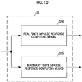
- the analysis signal computing means 32 is constituted of real finite impulse response computing means 324 and imaginary finite impulse response computing means 325.
- the real finite impulse response computing means 324 computes a convolutional product-sum of the output of the phase generating unit 21 and a real finite impulse response filter, and outputs a real part analysis signal.
- the imaginary finite impulse response computing means 325 computes a convolutional product-sum of the output of the phase generating unit 21 and an imaginary finite impulse response filter, and outputs an imaginary part analysis signal.
- two analysis signals that are perpendicular to each other can be obtained by subjecting a sinusoidal wave signal of a synthetic waveform output from the phase generating unit 21 to an analysis process.
- these two analysis signals that are perpendicular to each other are regarded as a real axis component and an imaginary axis component of a virtual vector of a sensor output signal
- the angle formed by this virtual vector with respect to a real axis is proportional to the displacement of the measured object. Therefore, the angular velocity of the measured object can be measured by time-differentiating this angle.
- the synthetic waveform of the magnetic sensors 11 and 12 output by the phase generating unit 21 is acquired by the angular velocity computing unit 23 as a one-cycle sinusoidal voltage waveform that is induced every time one of the meshing teeth 111 of the gear 100 passes from its opposite position.
- the angular velocity computing unit 23 can acquire a sinusoidal output waveform that is proportional to each rotational speed of the gear 100.
- the angular velocity computing unit 23 can acquire the frequency of the output waveform as a rotational frequency of the gear 100, and can acquire a rotational speed of the gear 100 at a specific moment from the output waveform.
- the CPU 151 of this computation unit 15 shown in FIG. 2 calculates an angular velocity of the gear 100 by acquiring sensor signals of the magnetic sensors 11 and 12 in accordance with the computation program in the memory 152 on a predetermined sampling cycle and carrying out an analysis process that will be described later.
- the sampling cycle for carrying out this analysis process is sufficiently shorter than one cycle of a sinusoidal wave as a synthetic waveform of the magnetic sensors 11 and 12, and is generally set to, for example, about one-tenth thereof.
- the synthetic waveform of the magnetic sensors 11 and 12 thus acquired by the computation unit 15 is amplified, subjected to A/D conversion, and then subjected to a signal process shown in a functional block diagram of FIG. 11 .
- FIG. 12 is a waveform diagram of respective portions that are processed by angular velocity measuring devices 10A and 10B, and the axis of abscissa and the axis of ordinate represent time and amplitudes of respective waveforms, respectively.
- a sinusoidal signal as indicated by S(t) in FIG. 12 is obtained as an output of the phase generating unit 21. That is, when ⁇ denotes a rotational angle of the gear 100, an equation (1) shown below is fulfilled.
- S t sin ⁇ / Z It should be noted, however, that the amplitude is normalized to 1.
- This analog signal S(t) is sent to each computation unit 15, subjected to A/D conversion, and processed into a digital signal. That is, N signals S(nT) (0 ⁇ n ⁇ N-1) sampled at a time interval T are derived by a Fourier transform unit 421 shown in FIG. 11 , and a complex spectrum G with a real part Gr and an imaginary part Gi is obtained based on equations (2) to (4) shown below.
- G k Gr k + jGi k
- N denotes a positive integer as a sampling numeral used for an analysis (which is referred to as an observation window length)
- n denotes a positive integer as a sampling number that satisfies 0 ⁇ n ⁇ N-1
- k denotes a number assigned to a frequency discretized individually for ⁇ f. That is, (2 ⁇ nk/N) denotes a discretized rotational angle.
- This complex spectrum is derived by a one-sided spectrum computing unit 422 shown in FIG. 11 , and the following processes are performed individually for the real part Gr and the imaginary part Gi.
- the spectrum of the negative frequency range is set to zero.
- the spectrum of the positive frequency range is doubled.
- a real part and an imaginary part of a one-sided spectrum output through these processes are denoted by Gr* and Gi* respectively.
- FIG. 12 shows waveforms of the real part Sr and the imaginary part Si of two analysis signals.
- V Sr + j ⁇ Si
- this virtual vector V forms an angle ⁇ with a virtually assumed real axis.
- This angle ⁇ is proportional to the rotational angle of the gear 100. That is, an angle computing unit 43 shown in FIG. 11 performs a computation according to an equation (6) shown below, so that the signals shown in FIG. 12 are obtained.
- ⁇ arctan Si / Sr
- the computation unit 15 can determine the detection accuracy by appropriately selecting the number Z of the meshing teeth 111 of the gear 100, and the sampling frequency f and the analysis window length N of a signal process.
- Each of the Fourier transform process, one-sided spectrum computing process, and inverse Fourier transform process in the computation unit 15 is a process in a frequency range. However, each of equivalent processes can also be performed in a time range.
- FIG. 13C is an illustrative view of a method of detecting a rotational speed.
- speed signals are obtained by the computation unit 15. For example, speed signals can be successively obtained even between a time point t0 and a time point t1, so the detection accuracy can be enhanced.
- the magnetic sensors 11 and 12 that detect the tooth flank shape of the gear 100 are arranged at shift positions that are offset from each other by 1/6 pitch, namely, ⁇ /3 phases in the rotational circumferential direction.
- a synthetic waveform as a substantially sinusoidal waveform is obtained with third-order harmonic components included in these sensor signals canceled, and then an analysis computation can be carried out.
- the angular velocity measuring device 10 can accurately calculate the angular velocity of the meshing teeth 111 of the gear 100 with high resolution capability. For example, as shown in FIG. 8B , fluctuations in the rotational speed of the gear 100 in which the tooth hammering phenomenon occurs can be output as a high-quality analysis waveform that can be easily grasped.
- the angular velocity measuring device 10 can be effectively utilized for various control processes by, for example, providing high-resolution capability information on the rotational angular velocity of the measured gear 100 to a control device for a vehicle that is mounted with the angular velocity measuring device 10.
- FIG. 14 is a view showing a relative angular velocity measuring device according to one of the embodiments of the invention that is equipped with two angular velocity measuring devices according to the invention.
- a relative angular velocity measuring device 50 is mounted in, for example, a vehicle and is installed for the purpose of measuring two gears 100A and 100B.
- the gears 100A and 100B are incorporated in a motive power transmission mechanism that transmits a motive power from a motive power source such as an internal combustion engine or the like, such as a transmission, a differential device or the like, and rotate while meshing with each other.
- This relative angular velocity measuring device 50 is structured by connecting a relative angle computing unit 25 to the two angular velocity measuring devices 10A and 10B according to the aforementioned embodiment of the invention, which are installed in such as manner as to be able to measure angular velocities of the gears 100A and 100B respectively.
- the relative angle computing unit 25 extracts fluctuations in the relative angular velocity of the gears 100A and 100B through the use of angular velocity information received from the angular velocity measuring devices 10A and 10B, and measures a meshing oscillation at the time of transmission of motive power by the two gears 100A and 100B, and the like.
- the gears 100A and 100B have a plurality of meshing teeth 111 A and 111B that are successively arranged in a circumferential direction of body portions 110A and 110B, which are fixed to rotary shafts 101A and 101B, and that mesh with each other.
- One of each pair of these meshing teeth 111A and 111B actively rotates due to the motive power transmitted from the motive power source of the vehicle, and the other of each pair of the meshing teeth 111A and 111B, which meshes with one thereof, passively rotates. As a result, the motive power is transmitted.
- the angular velocity measuring devices 10A and 10B are installed at such positions that two magnetic sensors 11A and 12A and two magnetic sensors 11B and 12B face, in a noncontact manner, tooth flanks 112A and 112B of the meshing teeth 111A and 111B of the gears 100A and 100B as measured objects, respectively.
- a computation unit 15A is connected to these magnetic sensors 11A and 12A via amplifiers 13A and 14A respectively.
- a computation unit 15B is connected to the magnetic sensors 11B and 12B via amplifiers 13B and 14B respectively.
- the computation units 15A and 15B are equipped with phase generating units 21A and 21B and angular velocity computing units 23A and 23B, respectively.
- the phase generating units 21A and 21B receive sensor signals from the magnetic sensors 11A and 12A and the magnetic sensors 11B and 12B respectively, generate a synthetic waveform as a substantially sinusoidal waveform with third-order harmonic components canceled from phase waveforms corresponding to the tooth flank shapes of the gears 100A and 100B respectively, and output the synthetic waveform.
- the angular velocity computing units 23A and 23B analyze output waveforms corresponding to the tooth flank shapes of the gears 100A and 100B for these phase generating units 21A and 21B respectively, and calculate angular velocities of the gears 100A and 100B respectively.
- each of the angular velocity computing units 23A and 23B is constituted of the analysis signal computing means 32, the angle computing means 33, and the angular velocity computing means 34.
- the analysis signal computing means 32 is constituted of the Fourier transform means 321, the one-sided spectrum computing means 322, and the inverse Fourier transform means 323, and also is constituted of the real finite impulse response computing means 324 and the imaginary finite impulse response computing means 325.
- the angular velocity computing units 23A and 23B acquire sinusoidal voltage waveforms (synthetic output waveforms) proportional to the rotational speeds of the gears 100A and 100B that are output from the phase generating units 21A and 21B, respectively.
- the angular velocity measuring devices 10A and 10B then calculate rotational frequencies of the gears 100A and 100B, and rotational speeds of the gears 100A and 100B at specific timings, respectively.
- the CPU 151 of each of the computation units 15A and 15B acquires a synthetic output waveform of each of the phase generating units 21A and 21B on a predetermined sampling cycle in accordance with the computation program in the memory 152, and performs the analysis process through the signal process shown in the functional block diagram of FIG. 11 .
- angular velocities of the gears 100A and 100B are calculated.
- a relative angular velocity of the gears 100A and 100B is calculated.
- the pair of the gears 100A and 100B preferably realize smooth and natural rotation through the setting for optimizing the gap between the tooth flanks 112A and 112B of the meshing teeth 111A and 111B that mesh with each other respectively, that is, a so-called backlash, in such a manner as to realize lossless delivery of the motive power transmitted from the motive power source.
- a so-called backlash in such a manner as to realize lossless delivery of the motive power transmitted from the motive power source.
- the backlash is too small, interference is caused. That is, for example, the tooth flanks 112A and 112B scrape against each other while being in press contact with each other.
- the amount of friction increases due to an insufficient amount of lubricating oil resulting from the lack of a sufficient gap.
- the relative angular velocity measuring device 50 realizes accurate measurement of the angular velocities of the gears 100A and 100B with high resolution capability through an analysis process of sensor signals excellent in S/N ratio by the two angular velocity measuring devices 10A and 10B.
- the relative angular velocity measuring device 50 makes it possible for the relative angle computing unit 25 to extract and grasp changes in the relative angular velocity through the use of high-quality information on the angular velocities of the gears 100A and 100B.
- the relative angle computing unit 25 of the relative angular velocity measuring device 50 can determine whether or not the gears 100A and 100B are set in such a state that the motive power can be transmitted with an optimal backlash, through the use of pieces of information on the angular velocities of the gears 100A and 100B that are output by the two angular velocity measuring devices 10A and 10B respectively.
- the relative angle computing unit 25 is structured by a CPU, a memory and the like separately from the computation units 15A and 15B or together with one of the computation units 15A and 15B.
- the CPU performs a computation process based on various parameters and the like in accordance with the computation program stored in advance in the memory.
- the relative angle computing unit 25 realizes the easy settings of the gears 100A and 100B by calculating angular velocities and a relative angular velocity of the respective gears 100A and 100B with high angle resolution capability, and displaying/outputting the calculated angular velocities and the calculated relative angular velocity on/to the display unit 27 or the like.
- the relative angle computing unit 25 is equipped with a liquid-crystal screen as the display unit 27, and displays/outputs changes in the angular velocities of the gears 100A and 100B within a certain period after digitalization thereof by average values, or displays/output the changes in the form of waveforms.
- the relative angle computing unit 25 displays/outputs changes in the difference between the angular velocities of the gears 100A and 100B within a certain period after digitalization by average values, or displays/outputs the changes in the form of a waveform.
- the relative angle computing unit 25 not only makes it possible to see a digitalized display of the average value of the difference between (the relative angular velocity of) the gears 100A and 100B, and to visually recognize meshing oscillation at the time of the transmission of motive power, the timings of the occurrence of tooth hammering and the like from the display of the waveform of changes in the difference, but may also determine and display/output whether or not the backlash is appropriate, through a comparison with a threshold.
- an operator can easily grasp set states of the gears 100A and 100B by checking the display unit 27, and can carry out a fine adjustment or the like of the set states.
- the tooth hammering behavior and the like may be made graspable with high accuracy through acquisition of relative retardation and relative advancement, by obtaining the difference after carrying out conversion into a peripheral speed per meshing.
- the relative angle computing unit 25 not only makes it possible to perform the act of displaying/outputting by being equipped with the display unit 27, but may be equipped with, for example, a connection terminal that is connected to an external device, and cause the external device to carry out an analysis or the like.
- the relative angular velocity measuring device 50 can acquire a relative angular velocity through the use of angular velocities of the gears 100A and 100B that are measured by the two angular velocity measuring devices 10A and 10B according to the aforementioned embodiment of the invention respectively.
- a setting operation or the like for effectively suppressing the generation of tooth hammering noise of the gears 100A and 100B can be easily carried out by, for example, easily grasping the magnitude of meshing oscillation, the presence or absence of tooth hammering and the like from the difference between the angular velocities, etc.
- the magnetic sensors 11 and 12 are installed successively in the circumferential direction at noncontact opposite positions close to the tooth flank 112 of each of the meshing teeth 111 of the gear 100 in the aforementioned embodiment of the invention, but the invention is not limited thereto.
- the magnetic sensors 11 and 12 in the case of a spur gear that is shaped such that the meshing teeth 111 of the gear 100 are extended parallel to an axial direction X of the rotary shaft 101, the magnetic sensors 11 and 12 sometimes cannot be installed at adjacent positions that are perpendicular to the axial direction of the rotary shaft 101 and that are successive to each other in a circumferential direction C, due to the small size of the gear 100, as shown in FIG. 15B .
- the magnetic sensors 11 and 12 may be arranged at shift positions that are offset from each other in a tooth width direction W of the gear 100. In this case as well, an operation and effect similar to those of the aforementioned embodiment of the invention can be obtained.
- the magnetic sensors 11 and 12 may be arranged at positions that are successive to each other on a straight line parallel to the axial direction X of the rotary shaft 101.
- an operation and effect similar to those of the aforementioned embodiment of the invention can be obtained.
- the tooth flank shape of the gear 100 is formed in such a manner as to include outer surfaces of the uniformly shaped meshing teeth 111 and to be successive in the circumferential direction, so the sensor signals that are output by the magnetic sensors 11 and 12 also assume a phase waveform on the cycle of the tooth flank shape including the meshing teeth 111.
- the magnetic sensors 11 and 12 may be arranged in an offset manner with respect to the meshing teeth 111, for example, at shift positions that are offset from the meshing teeth 111 by one or more teeth in the circumferential direction.
- the magnetic sensors 11 and 12 may be arranged at shift positions that are offset from each other by ⁇ (n-1)+(1/6) ⁇ pitch in the circumferential direction of the gear 100, when n denotes a natural number.
- the magnetic sensors 11 and 12 may be arranged at shift positions that are offset from each other by ⁇ (2 ⁇ (n-1)+( ⁇ /3) ⁇ phases in the phase waveforms of the sensor signals. In this case as well, an operation and effect similar to those of the aforementioned embodiment of the invention can be obtained.
- the magnetic sensors 11 and 12 are laid out such that the third-order harmonic components included in the sensor signals can be canceled has been described, but the invention is not limited thereto.
- a plurality of magnetic sensors may be used.
- magnetic sensors are additionally installed also at such positions that harmonic components of other orders can be cancelled from sensor signals thereof.
- the invention is not limited thereto.
- a similar operation and a similar effect can also be obtained by, for example, installing optical sensors capable of detecting the tooth flank shape of the gear instead of the magnetic sensors and synthesizing sensor signals of the optical sensors with each other.
- the use of the magnetic sensors as in the aforementioned embodiment of the invention is advantageous due to problems such as the space for installation, dirt and the like.
Landscapes
- Physics & Mathematics (AREA)
- General Physics & Mathematics (AREA)
- Transmission And Conversion Of Sensor Element Output (AREA)
Abstract
An angular velocity measuring device (10) measures an angular velocity of a gear (100) that is fixed to a rotary shaft (101). The angular velocity measuring device (10) includes a pair of magnetic sensors (11, 12) that are arranged at positions facing a tooth flank (112) of the gear and that detect a shape of the tooth flank in a noncontact manner, and a computation unit (15) that is configured to generate a waveform obtained by synthesizing output detection signals of the pair of the magnetic sensors with each other and output an output waveform and calculate the angular velocity of the gear from the output waveform. The magnetic sensors are arranged such that the output detection signals are offset from each other by {(n-1)+(1/6)} pitches when one pitch is defined as one cycle of the shape of the tooth flank in a circumferential direction of the gear.

Description
- The invention relates to an angular velocity measuring device and a relative angular velocity measuring device that accurately measure a rotational speed of a gear.
- A rotational speed of a gear is measured after appropriately selecting one among various measurement methods such as a method utilizing a rotary encoder, a method utilizing a photo interrupter, a method utilizing a magnetic sensor, and the like.
- In measuring a rotational speed of a gear that is mounted in a real machine such as a vehicle or the like, according to the measurement method utilizing the rotary encoder, the rotary encoder needs to be directly installed on a rotary shaft, so the space for installation is limited. Besides, in the case of the real machine, the installation itself of the rotary encoder in a measurable manner in a structure with a measured object in rotation is difficult. According to the measurement method utilizing the photo interrupter, a light path needs to be ensured, and the place for installation is limited due to the great influence of the environment. According to the measurement method utilizing the magnetic sensor, the problems caused by the measurement methods utilizing the rotary encoder and the photo interrupter are not serious. Therefore, the measurement method utilizing the magnetic sensor is suited to measure the rotational speed of the mounted gear.
- This measurement method for measuring the rotational speed is configured to acquire 0/1 signals each indicating whether or not a sensor signal exceeds a certain threshold, and calculate the rotational speed by counting the number of 0/1 signals. Therefore, changes in speed among the acquired sensor signals cannot be grasped with high resolution capability.
- Thus, Patent No.
3016656 - The angular velocity measuring device described in this Patent No.
3016656 - However, in the angular velocity measuring device described in Japanese Patent No.
3016656 JP 3016656 B - Incidentally, as will be described later, this problem is also caused in a similar manner in the angular velocity measuring device according to the measurement method utilizing the photo interrupter, in the case of a gear that does not have a precisely sinusoidal tooth flank shape.
- The invention provides an angular velocity measuring device and a relative angular velocity measuring device that can accurately acquire fluctuations in angular velocity, also in a gear that does not have sinusoidal tooth flanks.
- In one aspect of the invention, an angular velocity measuring device is configured to measure an angular velocity of a gear that is fixed to a rotary shaft. The angular velocity measuring device is equipped with a pair of a first noncontact sensor and a second noncontact sensor that are configured to be arranged at positions facing a tooth flank of the gear and to detect a shape of the tooth flank in a noncontact manner, and a computation unit that is configured to generate a waveform of a phase obtained by synthesizing output detection signals of the first noncontact sensor and the second noncontact sensor, output an output waveform, and calculate the angular velocity of the gear from the output waveform. The first noncontact sensor and the second noncontact sensor are arranged such that the output detection signals are offset from each other by {(n-1)+(1/6)} pitches when one pitch is defined as one cycle of the shape of the tooth flank in the circumferential direction of the gear and n denotes a natural number.
- As described hitherto, according to the aspect of the invention, the first noncontact sensor and the second noncontact sensor are arranged such that the output detection signals that have output waveforms corresponding to the shape of the tooth flank of the gear are offset from each other by {(n-1)+(1/6)} pitches of the shape of the tooth flank of the gear as a measured object. That is, the first noncontact sensor and the second noncontact sensor are arranged at positions that are offset from each other by (π/3) phase in the phase waveforms of output signal waveforms thereof, from a position where their output detection signals overlap with each other. Therefore, output detection signals having phase waveforms corresponding to fluctuations in the circumferential direction of the gear, which result from rotation of the tooth flank of the gear, are superimposed on each other while being offset from each other by (π/3) phase, and are synthesized with each other.
- At this time, the output detection signals from the first noncontact sensor and the second noncontact sensor include noise such as third-order harmonic components or the like, which is generated as a result of the fact that the shape of the tooth flank of the gear as a measured object is similar to a sinusoidal shape. In particular, the noise in the form of third-order harmonic components influences the accuracy in measuring the angular velocity. However, the respective output detection signals are synthesized with each other while being offset from each other by (π/3) phase. Thus, the intensity of the noise in the form of third-order harmonic components is reduced, and the output detection signals are output after being converted into a synthetic output waveform as a substantially sinusoidal high-quality phase waveform.
- Accordingly, even in the case where the shape of the tooth flank of the gear as a measured object does not coincide with a sinusoidal shape, the rotational speed of the gear can be accurately calculated with high resolution capability, and fluctuations in the highly accurate rotational speed of the gear can be easily grasped, by analyzing a substantially sinusoidal output waveform obtained by synthesizing the output detection signals for detecting the shape of the tooth flank with each other. As a result, an angular velocity measuring device that can accurately acquire fluctuations in angular velocity even in a gear that does not have a sinusoidal tooth flank can be provided.
- In the aspect of the invention, the gear may be configured as an involute gear.
- In the aspect of the invention, the first noncontact sensor and the second noncontact sensor may be configured as magnetic sensors.
- In the aspect of the invention, the magnetic sensors may be configured as eddy-current sensors, and the first noncontact sensor and the second noncontact sensor may be operated at different oscillating frequencies.
- In the aspect of the invention, the first noncontact sensor and the second noncontact sensor may be arranged at positions that are offset from each other in a circumferential direction of the gear.
- In the aspect of the invention, the first noncontact sensor and the second noncontact sensor may be arranged at positions that are offset from each other in a tooth width direction of the gear.
- In the aspect of the invention, the first noncontact sensor and the second noncontact sensor may be arranged at positions that are offset from each other in a tooth width direction of the gear and on a straight line parallel to an axial direction of the rotary shaft in a case where the gear is a helical gear.
- Besides, a relative angular velocity measuring device is equipped with at least two angular velocity measuring devices according to the aspect of the invention. The relative angular velocity measuring device is equipped with a relative angular velocity computing unit that is configured to measure angular velocities of a pair of the gears meshing with each other as measured by the angular velocity measuring devices respectively, and calculate a relative angular velocity between the gears. Therefore, the relative angular velocity measuring device that acquires the relative angular velocity of the gears that mesh with each other can be structured. For example, tooth hammering noise or the like that is generated when the teeth meshing with each other move into and out of contact with each other can be effectively and easily suppressed.
- Features, advantages, and technical and industrial significance of exemplary embodiments of the invention will be described below with reference to the accompanying drawings, in which like numerals denote like elements, and wherein:
-
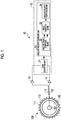
FIG. 1 is a view showing an angular velocity measuring device according to one of the embodiments of the invention, and is a conceptual view showing the general schematic configuration of the angular velocity measuring device; -
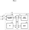
FIG. 2 is a block diagram showing the configuration of a computation unit of the angular velocity measuring device; -
FIG. 3A is a view illustrating the configuration of one magnetic sensor of the angular velocity measuring device, and is a layout diagram illustrating the arrangement of the magnetic sensor with respect to a gear; -
FIG. 3B is a graph illustrating a sensor output of the magnetic sensor; -
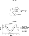
FIG. 4A is a view illustrating the configuration of a pair of magnetic sensors of the angular velocity measuring device, and is a layout diagram illustrating the arrangement of the pair of the magnetic sensors with respect to the gear; -
FIG. 4B is a graph illustrating sensor outputs of the pair of the magnetic sensors; -
FIG. 5A is a graph showing an output waveform model of the magnetic sensor at one base position of the angular velocity measuring device; -
FIG. 5B is a graph showing an output waveform model of the magnetic sensor at the other offset position of the angular velocity measuring device; -
FIG. 5C is a graph showing an output waveform at the time when respective sensor signals are synthesized with each other; -
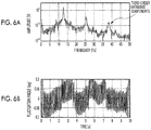
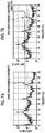
FIG. 6A is a graph showing harmonic components that are superimposed on a sensor signal of the magnetic sensor; -
FIG. 6B is a graph showing an analysis result of the sensor signal of the magnetic sensor; -
FIG. 7A is a graph showing harmonic components that are superimposed on sensor signals of the pair of the magnetic sensors that have not been synthesized with each other; -
FIG. 7B is a graph showing harmonic components that are superimposed on a sensor signal that is obtained after synthesizing sensor signals of the pair of the magnetic sensors with each other; -
FIG. 8A is a view showing an exemplary analysis result of a sensor signal of the magnetic sensor of the angular velocity measuring device, and is a graph showing timings of backlash resulting from fluctuations that are generated in a rotational direction of a pair of gears that rotate while meshing with each other; -
FIG. 8B is a view showing an exemplary analysis result of a sensor signal of the magnetic sensor of the angular velocity measuring device, and is a graph showing a rotational torque in the case where tooth hammering occurs when the gears rotate; -
FIG. 9 is a functional block diagram illustrating an analysis process of a sensor signal of the magnetic sensor of the angular velocity measuring device; -
FIG. 10 is a functional block diagram differing fromFIG. 9 and illustrating an analysis process of a sensor signal of the magnetic sensor of the angular velocity measuring device; -
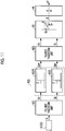
FIG. 11 is a functional block diagram differing fromFIGS. 9 and10 and illustrating an analysis process of a sensor signal of the magnetic sensor of the angular velocity measuring device; -
FIG. 12 includes waveform charts illustrating an analysis process of a sensor signal of the magnetic sensor of the angular velocity measuring device; -
FIG. 13 includes waveform charts illustrating a process of obtaining a rotational speed of the gear from an analysis result of a sensor signal of the magnetic sensor of the angular velocity measuring device; -
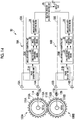
FIG. 14 is a view showing a relative angular velocity measuring device according to one of the embodiments of the invention that is equipped with two angular velocity measuring devices, and is a conceptual view showing the general schematic configuration of the relative angular velocity measuring device; -
FIG. 15A is a view illustrating an angular velocity measuring device according to a first additional aspect of the invention, and is a layout diagram of magnetic sensors as viewed from an axial direction of a spur gear; -
FIG. 15B is a layout diagram of the magnetic sensors with respect to a tooth flank of the spur gear in the first additional aspect of the invention; -
FIG. 15C is a layout diagram of the magnetic sensors with respect to the tooth flank of the spur gear, and is a layout diagram different fromFIG. 15B ; -
FIG. 16A is a view illustrating an angular velocity measuring device according to a second additional aspect of the invention, and is a layout diagram of magnetic sensors as viewed from an axial direction of a helical gear; -
FIG. 16B is a layout diagram of the magnetic sensors with respect to a tooth flank of the helical gear; and -
FIG. 17 is a view illustrating an angular velocity measuring device according to a third additional aspect of the invention, and is a conceptual view showing the general schematic configuration thereof. - The embodiments of the invention will be described hereinafter in detail with reference to the drawings.
FIGS. 1 to 13 are views showing an angular velocity measuring device according to one of the embodiments of the invention. - In
FIG. 1 , an angularvelocity measuring device 10 is mounted in, for example, a vehicle, and is installed for the purpose of measuring agear 100 that is incorporated in a motive power transmission mechanism that transmits motive power from a motive power source such as an internal combustion engine or the like, such as a transmission, a differential device or the like. Incidentally, this angularvelocity measuring device 10 may be mounted in a real machine such as a vehicle or the like in a steadily usable manner, or can also be used by being temporarily installed in adjusting the setting. - It should be noted herein that the
gear 100 is formed such that abody portion 110 and a plurality of meshingteeth 111 rotate integrally with arotary shaft 101. Thebody portion 110 has therotary shaft 101 fixed to a shaft center thereof, and assumes the shape of a circular disc, a circular column, or a circular cone. The plurality of the meshingteeth 111 are arranged on an outer peripheral surface of thisbody portion 110 successively in a circumferential direction around therotary shaft 101. Thisgear 100 is rotatably supported by a vehicle side such that therotary shaft 101 or the meshingteeth 111 receive the motive power transmitted from a motive power source of the vehicle and rotate in both a positive direction and a reverse direction or only in one of the directions. - This
gear 100 is an involute gear that is formed as follows. The meshingteeth 111 of thisgear 100 and meshingteeth 111 of anothergear 100 mesh with each other respectively, andtooth flanks 112 thereof are in press contact with each other respectively (seeFIG. 14 , which will be described later), such that motive power can be transmitted between thegears 100. Each of these tooth flanks 112 is formed such that an outer contour of a cross-section that is perpendicular to an axial direction, namely, a tooth flank shape coincides with an involute curve. - The angular
velocity measuring device 10 is structured by being equipped with a pair ofmagnetic sensors amplifiers magnetic sensors computation unit 15 that is connected such that outputs of theseamplifiers - The
magnetic sensors teeth 111 of thegear 100 in a noncontact manner, respectively. Each of themagnetic sensors magnetic sensors gear 100 in a noncontact manner, and detect fluctuations in the tooth flank shape in the circumferential direction that result from rotation of thegear 100. - Incidentally, as will be described later, these
magnetic sensors magnetic sensors magnetic sensors magnetic sensors magnetic sensors gear 100 as a measured object. Besides, thesemagnetic sensors magnetic sensors - The
amplifiers magnetic sensors - As shown in
FIG. 2 , thecomputation unit 15 is structured such that a central processing unit (a CPU) 151, amemory 152, an analog-digital converter (an A/D converter) 153, and anouter interface 154 are connected to one another via abus 159 in such a manner as to enable exchange of various information signals. Thiscomputation unit 15 acquires sensor signals of themagnetic sensors amplifiers D converter 153, and performs the computation process based on various parameters and the like in accordance with a computation program stored in advance into thememory 152 by theCPU 151. Thus, thecomputation unit 15 functions as aphase generating unit 21, an angularvelocity computing unit 23 and the like, which will be described later, and calculates a desired computation result. - As will be described later, the
magnetic sensors velocity measuring device 10 are arranged in an offset manner at shift positions that are offset from each other in a rotational direction of therotary shaft 101, such that thecomputation unit 15 can synthesize sensor signals of themagnetic sensors computation unit 15. - In concrete terms, as shown in
FIG. 3A , each of themagnetic sensors tooth flank 112 of each of the meshingteeth 111 of thegear 100 in a noncontact manner, and detects the tooth flank shape (fluctuations in the circumferential direction) of the rotating tooth flank in a tracing manner. Thus, as shown inFIG. 3B , each of themagnetic sensors - As shown in
FIG. 4A , thesemagnetic sensors gear 100, when one pitch is defined as one cycle of the tooth flank shape rotating in the circumferential direction of the tooth flanks 112 of the meshingteeth 111 of thegear 100. In other words, themagnetic sensors rotary shaft 101 by π/3 phases. As shown inFIG. 4B , an output waveform obtained by synthesizing sensor signals of themagnetic sensors - Thus, an output waveform model of a sensor signal of the
magnetic sensor 11 at a base position shown inFIG. 5A and an output waveform model of a sensor signal of themagnetic sensor 12 at a shift position of 1/6 pitch (π/3 phases) shown inFIG. 5B are synthesized with each other, and are output as a highly accurate synthesized waveform as a substantially sinusoidal waveform as shown inFIG. 5C . - By the way, the tooth flanks 112 of the meshing
teeth 111 of thegear 100 as a measured object are formed in the tooth flank shape corresponding to an involute curve. Therefore, as described above, the individual sensor signals of thesemagnetic sensors teeth 111 of thegear 100. Thus, as shown inFIG. 6A , third-order harmonic components are superimposed on each of these sensor signals due to the influence of the shapes of tooth tips of the meshingteeth 111, tooth roots of the meshingteeth 111, and flat portions among the tooth roots. - Therefore, even when a later-described computation process is performed to analyze each of sensor signals of these
magnetic sensors FIG. 6B . Then, fluctuations in the circumferential direction that result from rotation of the tooth flanks 112 of the meshingteeth 111 of thegear 100 are embedded in noise. As a result, for example, the timings of fluctuations to the extent of the occurrence of a tooth hammering phenomenon cannot be grasped. This problem causes a trouble in terms of accuracy, because an analysis process becomes complicated due to the necessity for the setting of a filter that is synchronized with a rotational speed in the case where the rotational speed changes, and a transient phenomenon is also removed by the filter, although apparent noise components can be reduced by subjecting the waveform data to a filtering process. - In contrast, with the
magnetic sensors FIG. 7A can be canceled by superimposing the sensor signals on each other and synthesizing them with each other. Thus, with the synthetic waveform of themagnetic sensors FIG. 7B . - Therefore, the angular
velocity measuring device 10 can realize the measurement of the angular velocity of thegear 100 with high angle resolution capability, by synthesizing two sensor signals of themagnetic sensors FIG. 8A , backlash can be extracted by actualizing fluctuations in the circumferential direction that result from rotation of the tooth flanks 112 of the meshingteeth 111 of thegear 100. It is possible to grasp that the rotation of thegear 100 fluctuates at timings when the tooth hammering phenomenon occurs upon torque inversion shown inFIG. 8B . - Specifically, returning to
FIG. 1 , thecomputation unit 15 of the angularvelocity measuring device 10 is equipped with thephase generating unit 21 and the angularvelocity computing unit 23 as described above. Thephase generating unit 21 cancels third-order harmonic components by receiving sensor signals of themagnetic sensors amplifiers gear 100, and outputs the synthetic waveform. The angularvelocity computing unit 23 analyzes an output waveform of thephase generating unit 21, and calculates an angular velocity of thegear 100. - The angular
velocity computing unit 23 is constituted of analysis signal computing means 32, angle computing means 33, and angular velocity computing means 34. The analysis signal computing means 32 calculates a real part analysis signal and an imaginary part analysis signal that form a Hilbert transform pair, by processing an output of thephase generating unit 21. The angle computing means 33 calculates an angle formed by the real part analysis signal and the imaginary part analysis signal, based on a ratio between the real part analysis signal and the imaginary part analysis signal, which have been computed by this analysis signal computing means 32. The angular velocity computing means 34 computes a time-derivative value of the angle computed by this angle computing means 33, and calculates an angular velocity. - As shown in
FIG. 9 , the analysis signal computing means 32 is constituted of Fourier transform means 321, one-sided spectrum computing means 322, and inverse Fourier transform means 323. The Fourier transform means 321 subjects the output of thephase generating unit 21 to complex Fourier transform, and calculates a real frequency component and an imaginary frequency component. The one-sided spectrum computing means 322 sets a negative frequency range of the real frequency component and the imaginary frequency component, which have been calculated by this Fourier transform means 321, to zero, doubles the value of a positive frequency range thereof, and calculates a one-sided real frequency component and a one-sided imaginary frequency component. The inverse Fourier transform means 323 outputs a real part analysis signal and an imaginary part analysis signal that form a Hilbert transform pair by subjecting the one-sided real frequency component and the one-sided imaginary frequency component, which have been calculated by this one-sided spectrum computing means 322, to inverse Fourier transform. - Besides, as shown in
FIG. 10 , the analysis signal computing means 32 is constituted of real finite impulse response computing means 324 and imaginary finite impulse response computing means 325. The real finite impulse response computing means 324 computes a convolutional product-sum of the output of thephase generating unit 21 and a real finite impulse response filter, and outputs a real part analysis signal. The imaginary finite impulse response computing means 325 computes a convolutional product-sum of the output of thephase generating unit 21 and an imaginary finite impulse response filter, and outputs an imaginary part analysis signal. - Thus, two analysis signals that are perpendicular to each other can be obtained by subjecting a sinusoidal wave signal of a synthetic waveform output from the
phase generating unit 21 to an analysis process. In the case where these two analysis signals that are perpendicular to each other are regarded as a real axis component and an imaginary axis component of a virtual vector of a sensor output signal, the angle formed by this virtual vector with respect to a real axis is proportional to the displacement of the measured object. Therefore, the angular velocity of the measured object can be measured by time-differentiating this angle. - Then, as described above, the synthetic waveform of the
magnetic sensors phase generating unit 21 is acquired by the angularvelocity computing unit 23 as a one-cycle sinusoidal voltage waveform that is induced every time one of the meshingteeth 111 of thegear 100 passes from its opposite position. Thus, the angularvelocity computing unit 23 can acquire a sinusoidal output waveform that is proportional to each rotational speed of thegear 100. For example, the angularvelocity computing unit 23 can acquire the frequency of the output waveform as a rotational frequency of thegear 100, and can acquire a rotational speed of thegear 100 at a specific moment from the output waveform. - The
CPU 151 of thiscomputation unit 15 shown inFIG. 2 calculates an angular velocity of thegear 100 by acquiring sensor signals of themagnetic sensors memory 152 on a predetermined sampling cycle and carrying out an analysis process that will be described later. Incidentally, the sampling cycle for carrying out this analysis process is sufficiently shorter than one cycle of a sinusoidal wave as a synthetic waveform of themagnetic sensors magnetic sensors computation unit 15 is amplified, subjected to A/D conversion, and then subjected to a signal process shown in a functional block diagram ofFIG. 11 . - Specifically,
FIG. 12 is a waveform diagram of respective portions that are processed by angularvelocity measuring devices FIG. 12 is obtained as an output of thephase generating unit 21. That is, when θ denotes a rotational angle of thegear 100, an equation (1) shown below is fulfilled.
- This analog signal S(t) is sent to each
computation unit 15, subjected to A/D conversion, and processed into a digital signal. That is, N signals S(nT) (0 ≤ n ≤ N-1) sampled at a time interval T are derived by aFourier transform unit 421 shown inFIG. 11 , and a complex spectrum G with a real part Gr and an imaginary part Gi is obtained based on equations (2) to (4) shown below.


- It should be noted, however, that N denotes a positive integer as a sampling numeral used for an analysis (which is referred to as an observation window length), that n denotes a positive integer as a sampling number that satisfies 0 ≤ n ≤ N-1, and that k denotes a number assigned to a frequency discretized individually for Δf. That is, (2πnk/N) denotes a discretized rotational angle.
- This complex spectrum is derived by a one-sided
spectrum computing unit 422 shown inFIG. 11 , and the following processes are performed individually for the real part Gr and the imaginary part Gi. (1) The spectrum of the negative frequency range is set to zero. (2) The spectrum of the positive frequency range is doubled. A real part and an imaginary part of a one-sided spectrum output through these processes are denoted by Gr* and Gi* respectively. - When the real part Gr* and the imaginary part Gi* of the one-sided spectrum are subjected to inverse Fourier transform by an inverse
Fourier transform unit 423 shown inFIG. 11 , a real part Sr and an imaginary part Si of mutually perpendicular analysis signals of an output S of thephase generating unit 21 shown inFIG. 12 are obtained. In the field of signal processes, the real part Sr and the imaginary part Si of these two analysis signals are assumed to form a Hilbert transform pair. -
FIG. 12 shows waveforms of the real part Sr and the imaginary part Si of two analysis signals. When the real part Sr and the imaginary part Si of these analysis signals are expressed on a complex plane, a virtual vector V indicated by an equation (5) shown below is obtained.
- Then, this virtual vector V forms an angle θ with a virtually assumed real axis. This angle θ is proportional to the rotational angle of the
gear 100. That is, anangle computing unit 43 shown inFIG. 11 performs a computation according to an equation (6) shown below, so that the signals shown inFIG. 12 are obtained.
- When Z denotes the number of the meshing
teeth 111 of thegear 100, the actual angle is equal to (θ/Z). An angular velocity computing unit 44 shown inFIG. 11 time-differentiates this angle, so an angular velocity ω of thegear 100 shown inFIG. 12 is computed.
- Incidentally, when Δω denotes a minimum detection accuracy of this angular velocity ω, an equation (8) shown below is fulfilled.

- Accordingly, the
computation unit 15 can determine the detection accuracy by appropriately selecting the number Z of the meshingteeth 111 of thegear 100, and the sampling frequency f and the analysis window length N of a signal process. Each of the Fourier transform process, one-sided spectrum computing process, and inverse Fourier transform process in thecomputation unit 15 is a process in a frequency range. However, each of equivalent processes can also be performed in a time range. - That is, when S(n) denotes an output signal of the
phase generating unit 21, hr(n) denotes an impulse response of the real finite impulse filter, hi(n) denotes an impulse response of an imaginary finite impulse filter, and n denotes a sample time point, the real part Sr and the imaginary part Si of the analysis signals can be calculated from equations (9) and (10) shown below.

- Incidentally, when a transfer function of a whole band pass filter is turned into a one-sided spectrum and subjected to complex inverse Fourier transform, the real finite impulse filter hr(n) can be obtained as the real part, and the imaginary finite impulse filter hi(n) can be obtained as the imaginary part.
FIG. 13C is an illustrative view of a method of detecting a rotational speed. InFIG. 13C , speed signals are obtained by thecomputation unit 15. For example, speed signals can be successively obtained even between a time point t0 and a time point t1, so the detection accuracy can be enhanced. - As described hitherto, in the angular
velocity measuring device 10 according to the present embodiment of the invention, themagnetic sensors gear 100 are arranged at shift positions that are offset from each other by 1/6 pitch, namely, π/3 phases in the rotational circumferential direction. Thus, a synthetic waveform as a substantially sinusoidal waveform is obtained with third-order harmonic components included in these sensor signals canceled, and then an analysis computation can be carried out. - Thus, the angular
velocity measuring device 10 can accurately calculate the angular velocity of the meshingteeth 111 of thegear 100 with high resolution capability. For example, as shown inFIG. 8B , fluctuations in the rotational speed of thegear 100 in which the tooth hammering phenomenon occurs can be output as a high-quality analysis waveform that can be easily grasped. - Accordingly, the angular
velocity measuring device 10 can be effectively utilized for various control processes by, for example, providing high-resolution capability information on the rotational angular velocity of the measuredgear 100 to a control device for a vehicle that is mounted with the angularvelocity measuring device 10. - Next,
FIG. 14 is a view showing a relative angular velocity measuring device according to one of the embodiments of the invention that is equipped with two angular velocity measuring devices according to the invention. - In
FIG. 14 , a relative angularvelocity measuring device 50 is mounted in, for example, a vehicle and is installed for the purpose of measuring twogears gears velocity measuring device 50 is structured by connecting a relativeangle computing unit 25 to the two angularvelocity measuring devices gears angle computing unit 25 extracts fluctuations in the relative angular velocity of thegears velocity measuring devices gears - It should be noted herein that the
gears teeth body portions rotary shafts teeth teeth - The angular
velocity measuring devices magnetic sensors magnetic sensors teeth gears computation unit 15A is connected to thesemagnetic sensors amplifiers 13A and 14A respectively. Besides, acomputation unit 15B is connected to themagnetic sensors amplifiers - The
computation units phase generating units velocity computing units phase generating units magnetic sensors magnetic sensors gears velocity computing units gears phase generating units gears - These angular
velocity computing units velocity computing units - Then, as is the case with the aforementioned embodiment of the invention, the angular
velocity computing units gears phase generating units velocity measuring devices gears gears - At this time, as is the case with the aforementioned embodiment of the invention, the
CPU 151 of each of thecomputation units phase generating units memory 152, and performs the analysis process through the signal process shown in the functional block diagram ofFIG. 11 . Thus, angular velocities of thegears gears - By the way, the pair of the
gears teeth gears - For this reason, it is effective to set the
gears velocity measuring device 50 realizes accurate measurement of the angular velocities of thegears velocity measuring devices velocity measuring device 50 makes it possible for the relativeangle computing unit 25 to extract and grasp changes in the relative angular velocity through the use of high-quality information on the angular velocities of thegears - In concrete terms, the relative
angle computing unit 25 of the relative angularvelocity measuring device 50 can determine whether or not thegears gears velocity measuring devices - As is the case with the angular
velocity computing units angle computing unit 25 is structured by a CPU, a memory and the like separately from thecomputation units computation units angle computing unit 25, the CPU performs a computation process based on various parameters and the like in accordance with the computation program stored in advance in the memory. Thus, the relativeangle computing unit 25 realizes the easy settings of thegears respective gears display unit 27 or the like. - For example, the relative
angle computing unit 25 is equipped with a liquid-crystal screen as thedisplay unit 27, and displays/outputs changes in the angular velocities of thegears angle computing unit 25 displays/outputs changes in the difference between the angular velocities of thegears angle computing unit 25 not only makes it possible to see a digitalized display of the average value of the difference between (the relative angular velocity of) thegears - Thus, an operator can easily grasp set states of the
gears display unit 27, and can carry out a fine adjustment or the like of the set states. - It should be noted herein that when the number of teeth of the
gear 100A and the number of teeth of thegear 100B are different from each other, the tooth hammering behavior and the like may be made graspable with high accuracy through acquisition of relative retardation and relative advancement, by obtaining the difference after carrying out conversion into a peripheral speed per meshing. - Incidentally, the relative
angle computing unit 25 not only makes it possible to perform the act of displaying/outputting by being equipped with thedisplay unit 27, but may be equipped with, for example, a connection terminal that is connected to an external device, and cause the external device to carry out an analysis or the like. - As described hitherto, in addition to the operation and effect resulting from the aforementioned embodiment of the invention, the relative angular
velocity measuring device 50 according to the present embodiment of the invention can acquire a relative angular velocity through the use of angular velocities of thegears velocity measuring devices gears - It should be noted herein that as a first additional aspect of the aforementioned embodiment of the invention, as shown in
FIGS. 15A and 15B , themagnetic sensors tooth flank 112 of each of the meshingteeth 111 of thegear 100 in the aforementioned embodiment of the invention, but the invention is not limited thereto. For example, in the case of a spur gear that is shaped such that the meshingteeth 111 of thegear 100 are extended parallel to an axial direction X of therotary shaft 101, themagnetic sensors rotary shaft 101 and that are successive to each other in a circumferential direction C, due to the small size of thegear 100, as shown inFIG. 15B . In this case, as shown inFIG. 15C , themagnetic sensors gear 100. In this case as well, an operation and effect similar to those of the aforementioned embodiment of the invention can be obtained. - Besides, as a second additional aspect of the aforementioned embodiment of the invention, as shown in
FIGS. 16A and 16B , in the case of, for example, a helical gear that is shaped such that the meshingteeth 111 of thegear 100 are extended in a diagonal direction that intersects with the axial direction X of therotary shaft 101, themagnetic sensors rotary shaft 101. In this case as well, an operation and effect similar to those of the aforementioned embodiment of the invention can be obtained. - Furthermore, as a third additional aspect of the aforementioned embodiment of the invention, the tooth flank shape of the
gear 100 is formed in such a manner as to include outer surfaces of the uniformly shaped meshingteeth 111 and to be successive in the circumferential direction, so the sensor signals that are output by themagnetic sensors teeth 111. Thus, as shown inFIG. 17 , themagnetic sensors teeth 111, for example, at shift positions that are offset from the meshingteeth 111 by one or more teeth in the circumferential direction. That is, themagnetic sensors gear 100, when n denotes a natural number. In other words, themagnetic sensors - Besides, in the aforementioned embodiment of the invention, the example in which the
magnetic sensors - Furthermore, in the aforementioned embodiment of the invention, the example in which the
magnetic sensors - Although the embodiments of the invention have been disclosed, it is obvious that those skilled in the art can alter the embodiments of the invention without departing from the scope thereof. The following claims of the invention are intended to encompass all such modifications and equivalents.
Claims (8)
- An angular velocity measuring device (10) that is configured to measure an angular velocity of a gear (100) that is fixed to a rotary shaft (101), comprising:a pair of a first noncontact sensor (11) and a second noncontact sensor (12) that are configured to be arranged at positions facing a tooth flank (112) of the gear (100) and to detect a shape of the tooth flank in a noncontact manner; anda computation unit (15) that is configured to generate a waveform of a phase obtained by synthesizing output detection signals of the first noncontact sensor (11) and the second noncontact sensor (12), output an output waveform, and calculate the angular velocity of the gear (100) from the output waveform, whereinthe first noncontact sensor (11) and the second noncontact sensor (12) are arranged such that the output detection signals are offset from each other by {(n-1)+(1/6)} pitches when one pitch is defined as one cycle of the shape of the tooth flank in the circumferential direction of the gear (100) and n denotes a natural number.
- The angular velocity measuring device (10) according to claim 1, wherein
the gear (100) is configured as an involute gear. - The angular velocity measuring device (10) according to claim 1 or 2, wherein
the first noncontact sensor (11) and the second noncontact sensor (12) are configured as magnetic sensors. - The angular velocity measuring device (10) according to claim 3, wherein
the magnetic sensors are configured as eddy-current sensors, and
the first noncontact sensor (11) and the second noncontact sensor (12) are configured to be operated at different oscillating frequencies. - The angular velocity measuring device (10) according to any one of claims 1 to 4, wherein
the first noncontact sensor (11) and the second noncontact sensor (12) are arranged at positions that are offset from each other in a circumferential direction of the gear (100). - The angular velocity measuring device (10) according to claim5, wherein
the first noncontact sensor (11) and the second noncontact sensor (12) are arranged at positions that are offset from each other in a tooth width direction of the gear (100). - The angular velocity measuring device (10) according to any one of claims 1 to 4, wherein
the first noncontact sensor (11) and the second noncontact sensor (12) are arranged at positions that are offset from each other in a tooth width direction of the gear (100) and on a straight line parallel to an axial direction of the rotary shaft (101) in a case where the gear (100) is a helical gear. - A relative angular velocity measuring device (50) that is equipped with at least two angular velocity measuring devices (10) according to any one of claims 1 to 7, comprising:a relative angular velocity computing unit (25) that is configured to measure angular velocities of a pair of the gears meshing with each other as measured by the angular velocity measuring devices (10) respectively, and calculate a relative angular velocity between the gears.
Applications Claiming Priority (1)
| Application Number | Priority Date | Filing Date | Title |
|---|---|---|---|
| JP2016192120A JP2018054510A (en) | 2016-09-29 | 2016-09-29 | Angular velocity measurement device and relative angular velocity measurement device |
Publications (1)
| Publication Number | Publication Date |
|---|---|
| EP3301455A2 true EP3301455A2 (en) | 2018-04-04 |
Family
ID=59997083
Family Applications (1)
| Application Number | Title | Priority Date | Filing Date |
|---|---|---|---|
| EP17192461.6A Withdrawn EP3301455A2 (en) | 2016-09-29 | 2017-09-21 | Angular velocity measuring device and relative angular velocity measuring device |
Country Status (4)
| Country | Link |
|---|---|
| US (1) | US20180088144A1 (en) |
| EP (1) | EP3301455A2 (en) |
| JP (1) | JP2018054510A (en) |
| CN (1) | CN107884594A (en) |
Families Citing this family (10)
| Publication number | Priority date | Publication date | Assignee | Title |
|---|---|---|---|---|
| US10495659B2 (en) * | 2017-11-06 | 2019-12-03 | Rolls-Royce Corporation | Speed and position sensing systems |
| JP2019148477A (en) * | 2018-02-27 | 2019-09-05 | セイコーエプソン株式会社 | Angular velocity sensor, inertia measurement device, moving body positioning device, portable type electronic device, electronic device, and moving body |
| CN109655083B (en) * | 2019-02-15 | 2021-10-08 | 广州极飞科技股份有限公司 | Magnetic encoder, calibration method and calibration device, motor and unmanned aerial vehicle |
| CN109889114A (en) * | 2019-02-15 | 2019-06-14 | 广州极飞科技有限公司 | The calibration method and calibrating installation of magnetic coder, motor, peristaltic pump and perfusion machine |
| CN110045139B (en) * | 2019-03-26 | 2021-02-09 | 天津鼎成高新技术产业有限公司 | Rotating speed measuring system based on pulse time |
| CN114303040B (en) * | 2020-06-23 | 2026-04-21 | 株式会社定石化学 | Method and device for pedestrian information recognition using multiple magnetic sensors |
| US11441501B2 (en) * | 2021-01-08 | 2022-09-13 | Toyota Jidosha Kabushiki Kaisha | Controller for vehicle and method for controlling vehicle |
| US11796557B2 (en) * | 2021-02-24 | 2023-10-24 | Infineon Technologies Ag | Twist insensitive mounting differential speed sensor with direction detection |
| CN113295881A (en) * | 2021-06-17 | 2021-08-24 | 工业互联网创新中心(上海)有限公司 | High-precision wire feeding speed measuring device and method for general industrial welding machine |
| CN113309618B (en) * | 2021-06-30 | 2022-08-02 | 中国航发动力股份有限公司 | Troubleshooting method for low-pressure rotating speed signal fluctuation of gas turbine |
Citations (2)
| Publication number | Priority date | Publication date | Assignee | Title |
|---|---|---|---|---|
| JPS646656B2 (en) | 1983-08-11 | 1989-02-06 | Tonen Sekiyukagaku Kk | |
| JP3016656B2 (en) | 1992-04-13 | 2000-03-06 | 株式会社日本自動車部品総合研究所 | Angular velocity measuring device |
Family Cites Families (4)
| Publication number | Priority date | Publication date | Assignee | Title |
|---|---|---|---|---|
| JPS62204118A (en) * | 1986-03-05 | 1987-09-08 | Hitachi Ltd | A device that magnetically detects position or speed |
| JP2952151B2 (en) * | 1993-07-30 | 1999-09-20 | トヨタ自動車株式会社 | Wheel disturbance detection device and its use |
| CN2553383Y (en) * | 2002-07-09 | 2003-05-28 | 长沙南车电气设备有限公司 | Phase output magnetoelectric speed sensor |
| CN1851473A (en) * | 2006-05-23 | 2006-10-25 | 山西科泰微技术有限公司 | Angular speed measuring method and device |
-
2016
- 2016-09-29 JP JP2016192120A patent/JP2018054510A/en not_active Withdrawn
-
2017
- 2017-09-14 US US15/704,493 patent/US20180088144A1/en not_active Abandoned
- 2017-09-21 EP EP17192461.6A patent/EP3301455A2/en not_active Withdrawn
- 2017-09-25 CN CN201710874924.8A patent/CN107884594A/en active Pending
Patent Citations (2)
| Publication number | Priority date | Publication date | Assignee | Title |
|---|---|---|---|---|
| JPS646656B2 (en) | 1983-08-11 | 1989-02-06 | Tonen Sekiyukagaku Kk | |
| JP3016656B2 (en) | 1992-04-13 | 2000-03-06 | 株式会社日本自動車部品総合研究所 | Angular velocity measuring device |
Also Published As
| Publication number | Publication date |
|---|---|
| CN107884594A (en) | 2018-04-06 |
| JP2018054510A (en) | 2018-04-05 |
| US20180088144A1 (en) | 2018-03-29 |
Similar Documents
| Publication | Publication Date | Title |
|---|---|---|
| EP3301455A2 (en) | Angular velocity measuring device and relative angular velocity measuring device | |
| CN102483368B (en) | Method for detecting structural defect in mechanical assembly including rotary member | |
| Chin et al. | Absolute transmission error: A simple new tool for assessing gear wear | |
| Tuma | Gearbox noise and vibration prediction and control | |
| Meltzer et al. | Fault detection in gear drives with non-stationary rotational speed-part I: the time-frequency approach | |
| TWI518310B (en) | Gear accuracy detection method | |
| Li et al. | A new strategy of instantaneous angular speed extraction and its application to multistage gearbox fault diagnosis | |
| CN102279068B (en) | The method of moment of torsion, measurement mechanism and control program is detected in gear train | |
| EP0801730B1 (en) | Apparatus for inspecting a gear | |
| US11927501B2 (en) | Method and device for monitoring a gear system | |
| CN102305712A (en) | Error tracing method for nonuniform transmission system by sampling at equal time intervals | |
| JP5218614B2 (en) | Abnormality diagnosis device, rotating device, railway vehicle, automobile and abnormality diagnosis method | |
| CN102269803B (en) | Method for correcting low-frequency components in discrete spectrum based on time delay | |
| CN117232794A (en) | Rotating machinery fault detection method based on multi-component sparse time domain synchronous averaging | |
| Liu et al. | Residual angular speed analysis based on laser Doppler vibrometer and its application in planetary gearbox diagnosis | |
| KR20150138991A (en) | Harmonic drive torque sensing device | |
| EP2130021B1 (en) | Pitch line run-out detection apparatus | |
| Meroño et al. | Measurement techniques of torsional vibration in rotating shafts | |
| JPWO2019216235A1 (en) | Angle detector | |
| JP5466104B2 (en) | Rotation detection apparatus and method | |
| Sweeney | Transmission error measurement and analysis | |
| JP3720704B2 (en) | Error measuring method and apparatus for gear eccentricity, etc. | |
| Tuma | Phase demodulation of impulse signals in machine shaft angular vibration measurements | |
| JPH0733977B2 (en) | Gear abnormality diagnostic device | |
| JP2007003507A (en) | Gear inspection device |
Legal Events
| Date | Code | Title | Description |
|---|---|---|---|
| PUAI | Public reference made under article 153(3) epc to a published international application that has entered the european phase |
Free format text: ORIGINAL CODE: 0009012 |
|
| STAA | Information on the status of an ep patent application or granted ep patent |
Free format text: STATUS: THE APPLICATION HAS BEEN WITHDRAWN |
|
| 17P | Request for examination filed |
Effective date: 20170921 |
|
| AK | Designated contracting states |
Kind code of ref document: A2 Designated state(s): AL AT BE BG CH CY CZ DE DK EE ES FI FR GB GR HR HU IE IS IT LI LT LU LV MC MK MT NL NO PL PT RO RS SE SI SK SM TR |
|
| AX | Request for extension of the european patent |
Extension state: BA ME |
|
| 18W | Application withdrawn |
Effective date: 20180322 |