EP3301321A1 - Shock absorber, vehicle, and snowmobile - Google Patents
Shock absorber, vehicle, and snowmobile Download PDFInfo
- Publication number
- EP3301321A1 EP3301321A1 EP17187630.3A EP17187630A EP3301321A1 EP 3301321 A1 EP3301321 A1 EP 3301321A1 EP 17187630 A EP17187630 A EP 17187630A EP 3301321 A1 EP3301321 A1 EP 3301321A1
- Authority
- EP
- European Patent Office
- Prior art keywords
- cylinder
- rod
- shock absorber
- mounting member
- piston
- Prior art date
- Legal status (The legal status is an assumption and is not a legal conclusion. Google has not performed a legal analysis and makes no representation as to the accuracy of the status listed.)
- Granted
Links
- 230000035939 shock Effects 0.000 title claims abstract description 105
- 239000006096 absorbing agent Substances 0.000 title claims abstract description 103
- 238000004891 communication Methods 0.000 claims abstract description 24
- 238000005192 partition Methods 0.000 claims abstract description 5
- 230000008878 coupling Effects 0.000 description 12
- 238000010168 coupling process Methods 0.000 description 12
- 238000005859 coupling reaction Methods 0.000 description 12
- 230000008602 contraction Effects 0.000 description 8
- 230000004048 modification Effects 0.000 description 7
- 238000012986 modification Methods 0.000 description 7
- 230000005540 biological transmission Effects 0.000 description 6
- 238000013016 damping Methods 0.000 description 4
- 230000002411 adverse Effects 0.000 description 3
- 238000005452 bending Methods 0.000 description 2
- 238000006243 chemical reaction Methods 0.000 description 2
- 230000006835 compression Effects 0.000 description 2
- 238000007906 compression Methods 0.000 description 2
- 230000001788 irregular Effects 0.000 description 2
- 238000000034 method Methods 0.000 description 2
- 238000002485 combustion reaction Methods 0.000 description 1
- 230000001419 dependent effect Effects 0.000 description 1
- 230000000694 effects Effects 0.000 description 1
- 230000005764 inhibitory process Effects 0.000 description 1
Images




Classifications
-
- F—MECHANICAL ENGINEERING; LIGHTING; HEATING; WEAPONS; BLASTING
- F16—ENGINEERING ELEMENTS AND UNITS; GENERAL MEASURES FOR PRODUCING AND MAINTAINING EFFECTIVE FUNCTIONING OF MACHINES OR INSTALLATIONS; THERMAL INSULATION IN GENERAL
- F16F—SPRINGS; SHOCK-ABSORBERS; MEANS FOR DAMPING VIBRATION
- F16F9/00—Springs, vibration-dampers, shock-absorbers, or similarly-constructed movement-dampers using a fluid or the equivalent as damping medium
- F16F9/32—Details
- F16F9/3207—Constructional features
- F16F9/3221—Constructional features of piston rods
-
- B—PERFORMING OPERATIONS; TRANSPORTING
- B60—VEHICLES IN GENERAL
- B60G—VEHICLE SUSPENSION ARRANGEMENTS
- B60G13/00—Resilient suspensions characterised by arrangement, location or type of vibration dampers
- B60G13/001—Arrangements for attachment of dampers
- B60G13/003—Arrangements for attachment of dampers characterised by the mounting on the vehicle body or chassis of the damper unit
-
- B—PERFORMING OPERATIONS; TRANSPORTING
- B60—VEHICLES IN GENERAL
- B60G—VEHICLE SUSPENSION ARRANGEMENTS
- B60G17/00—Resilient suspensions having means for adjusting the spring or vibration-damper characteristics, for regulating the distance between a supporting surface and a sprung part of vehicle or for locking suspension during use to meet varying vehicular or surface conditions, e.g. due to speed or load
- B60G17/06—Characteristics of dampers, e.g. mechanical dampers
- B60G17/08—Characteristics of fluid dampers
-
- F—MECHANICAL ENGINEERING; LIGHTING; HEATING; WEAPONS; BLASTING
- F16—ENGINEERING ELEMENTS AND UNITS; GENERAL MEASURES FOR PRODUCING AND MAINTAINING EFFECTIVE FUNCTIONING OF MACHINES OR INSTALLATIONS; THERMAL INSULATION IN GENERAL
- F16F—SPRINGS; SHOCK-ABSORBERS; MEANS FOR DAMPING VIBRATION
- F16F9/00—Springs, vibration-dampers, shock-absorbers, or similarly-constructed movement-dampers using a fluid or the equivalent as damping medium
- F16F9/06—Springs, vibration-dampers, shock-absorbers, or similarly-constructed movement-dampers using a fluid or the equivalent as damping medium using both gas and liquid
- F16F9/064—Units characterised by the location or shape of the expansion chamber
- F16F9/065—Expansion chamber provided on the upper or lower end of a damper, separately there from or laterally on the damper
-
- F—MECHANICAL ENGINEERING; LIGHTING; HEATING; WEAPONS; BLASTING
- F16—ENGINEERING ELEMENTS AND UNITS; GENERAL MEASURES FOR PRODUCING AND MAINTAINING EFFECTIVE FUNCTIONING OF MACHINES OR INSTALLATIONS; THERMAL INSULATION IN GENERAL
- F16F—SPRINGS; SHOCK-ABSORBERS; MEANS FOR DAMPING VIBRATION
- F16F9/00—Springs, vibration-dampers, shock-absorbers, or similarly-constructed movement-dampers using a fluid or the equivalent as damping medium
- F16F9/10—Springs, vibration-dampers, shock-absorbers, or similarly-constructed movement-dampers using a fluid or the equivalent as damping medium using liquid only; using a fluid of which the nature is immaterial
- F16F9/14—Devices with one or more members, e.g. pistons, vanes, moving to and fro in chambers and using throttling effect
- F16F9/16—Devices with one or more members, e.g. pistons, vanes, moving to and fro in chambers and using throttling effect involving only straight-line movement of the effective parts
- F16F9/18—Devices with one or more members, e.g. pistons, vanes, moving to and fro in chambers and using throttling effect involving only straight-line movement of the effective parts with a closed cylinder and a piston separating two or more working spaces therein
- F16F9/20—Devices with one or more members, e.g. pistons, vanes, moving to and fro in chambers and using throttling effect involving only straight-line movement of the effective parts with a closed cylinder and a piston separating two or more working spaces therein with the piston-rod extending through both ends of the cylinder, e.g. constant-volume dampers
-
- F—MECHANICAL ENGINEERING; LIGHTING; HEATING; WEAPONS; BLASTING
- F16—ENGINEERING ELEMENTS AND UNITS; GENERAL MEASURES FOR PRODUCING AND MAINTAINING EFFECTIVE FUNCTIONING OF MACHINES OR INSTALLATIONS; THERMAL INSULATION IN GENERAL
- F16F—SPRINGS; SHOCK-ABSORBERS; MEANS FOR DAMPING VIBRATION
- F16F9/00—Springs, vibration-dampers, shock-absorbers, or similarly-constructed movement-dampers using a fluid or the equivalent as damping medium
- F16F9/32—Details
- F16F9/36—Special sealings, including sealings or guides for piston-rods
- F16F9/362—Combination of sealing and guide arrangements for piston rods
-
- F—MECHANICAL ENGINEERING; LIGHTING; HEATING; WEAPONS; BLASTING
- F16—ENGINEERING ELEMENTS AND UNITS; GENERAL MEASURES FOR PRODUCING AND MAINTAINING EFFECTIVE FUNCTIONING OF MACHINES OR INSTALLATIONS; THERMAL INSULATION IN GENERAL
- F16F—SPRINGS; SHOCK-ABSORBERS; MEANS FOR DAMPING VIBRATION
- F16F9/00—Springs, vibration-dampers, shock-absorbers, or similarly-constructed movement-dampers using a fluid or the equivalent as damping medium
- F16F9/32—Details
- F16F9/54—Arrangements for attachment
-
- B—PERFORMING OPERATIONS; TRANSPORTING
- B60—VEHICLES IN GENERAL
- B60G—VEHICLE SUSPENSION ARRANGEMENTS
- B60G2200/00—Indexing codes relating to suspension types
- B60G2200/10—Independent suspensions
- B60G2200/14—Independent suspensions with lateral arms
- B60G2200/144—Independent suspensions with lateral arms with two lateral arms forming a parallelogram
-
- B—PERFORMING OPERATIONS; TRANSPORTING
- B60—VEHICLES IN GENERAL
- B60G—VEHICLE SUSPENSION ARRANGEMENTS
- B60G2200/00—Indexing codes relating to suspension types
- B60G2200/10—Independent suspensions
- B60G2200/14—Independent suspensions with lateral arms
- B60G2200/156—Independent suspensions with lateral arms wishbone-type arm formed by two links defining a virtual apex
-
- B—PERFORMING OPERATIONS; TRANSPORTING
- B60—VEHICLES IN GENERAL
- B60G—VEHICLE SUSPENSION ARRANGEMENTS
- B60G2202/00—Indexing codes relating to the type of spring, damper or actuator
- B60G2202/30—Spring/Damper and/or actuator Units
- B60G2202/31—Spring/Damper and/or actuator Units with the spring arranged around the damper, e.g. MacPherson strut
- B60G2202/312—The spring being a wound spring
-
- B—PERFORMING OPERATIONS; TRANSPORTING
- B60—VEHICLES IN GENERAL
- B60G—VEHICLE SUSPENSION ARRANGEMENTS
- B60G2204/00—Indexing codes related to suspensions per se or to auxiliary parts
- B60G2204/10—Mounting of suspension elements
- B60G2204/12—Mounting of springs or dampers
- B60G2204/128—Damper mount on vehicle body or chassis
-
- B—PERFORMING OPERATIONS; TRANSPORTING
- B60—VEHICLES IN GENERAL
- B60G—VEHICLE SUSPENSION ARRANGEMENTS
- B60G2300/00—Indexing codes relating to the type of vehicle
- B60G2300/12—Cycles; Motorcycles
- B60G2300/124—Quads
-
- B—PERFORMING OPERATIONS; TRANSPORTING
- B60—VEHICLES IN GENERAL
- B60G—VEHICLE SUSPENSION ARRANGEMENTS
- B60G2300/00—Indexing codes relating to the type of vehicle
- B60G2300/32—Track vehicles
- B60G2300/322—Snowmobiles
-
- F—MECHANICAL ENGINEERING; LIGHTING; HEATING; WEAPONS; BLASTING
- F16—ENGINEERING ELEMENTS AND UNITS; GENERAL MEASURES FOR PRODUCING AND MAINTAINING EFFECTIVE FUNCTIONING OF MACHINES OR INSTALLATIONS; THERMAL INSULATION IN GENERAL
- F16F—SPRINGS; SHOCK-ABSORBERS; MEANS FOR DAMPING VIBRATION
- F16F2230/00—Purpose; Design features
- F16F2230/0005—Attachment, e.g. to facilitate mounting onto confer adjustability
-
- F—MECHANICAL ENGINEERING; LIGHTING; HEATING; WEAPONS; BLASTING
- F16—ENGINEERING ELEMENTS AND UNITS; GENERAL MEASURES FOR PRODUCING AND MAINTAINING EFFECTIVE FUNCTIONING OF MACHINES OR INSTALLATIONS; THERMAL INSULATION IN GENERAL
- F16F—SPRINGS; SHOCK-ABSORBERS; MEANS FOR DAMPING VIBRATION
- F16F9/00—Springs, vibration-dampers, shock-absorbers, or similarly-constructed movement-dampers using a fluid or the equivalent as damping medium
- F16F9/06—Springs, vibration-dampers, shock-absorbers, or similarly-constructed movement-dampers using a fluid or the equivalent as damping medium using both gas and liquid
- F16F9/08—Springs, vibration-dampers, shock-absorbers, or similarly-constructed movement-dampers using a fluid or the equivalent as damping medium using both gas and liquid where gas is in a chamber with a flexible wall
- F16F9/096—Springs, vibration-dampers, shock-absorbers, or similarly-constructed movement-dampers using a fluid or the equivalent as damping medium using both gas and liquid where gas is in a chamber with a flexible wall comprising a hydropneumatic accumulator of the membrane type provided on the upper or the lower end of a damper or separately from or laterally on the damper
Definitions
- the present invention relates to a shock absorber, a vehicle, and a snowmobile.
- one rod coupled to a piston provided inside a cylinder extends externally from one end portion of the cylinder.
- Oil filling the cylinder is pressurized by a high-pressure gas, a spring, or the like.
- a force is exerted on the rod in a direction in which the rod projects from the cylinder by a pressure received by the piston from the oil.
- the force generated by a hydraulic pressure is exerted on the shock absorber in an extension direction.
- the shock absorber in which the force generated by the hydraulic pressure is exerted in the extension direction as described above may not sufficiently absorb a shock received from a ground surface, resulting in a fear of adversely affecting riding comfort of a vehicle. Further, timing of a load shift to an outer wheel or ski is likely to be advanced at cornering, also resulting in the fear of adversely affecting the riding comfort of the vehicle.
- a diameter of the sub-piston rod is set larger than a diameter of the main piston rod to be coupled externally.
- the shock absorber in which the force generated by the hydraulic pressure is exerted in the contraction direction as described above can solve the problem of the above-mentioned shock absorber in which the force generated by the hydraulic pressure is exerted in the extension direction so as to improve the riding comfort of the vehicle.
- a cylinder tube is formed about twice as long as an interval between a first rod guide and a second rod guide so as to accommodate the sub-piston rod extending from the second rod guide.
- the shock absorber to be applied to a vehicle for running on an irregular ground such as a recreational off-highway vehicle (ROV) or a snowmobile, is required to ensure ability to absorb the shock.
- ROV recreational off-highway vehicle
- a snowmobile is required to ensure ability to absorb the shock.
- a shock absorber having the features of independent claim 1 and by a vehicle and a snowmobile having at least one of such shock absorber.
- Preferred embodiments are laid down in the dependent claims.
- a shock absorber includes a cylinder, a piston, which is configured to partition an internal space of the cylinder into two oil chambers, and is capable of sliding in an axial direction of the cylinder, the piston having formed therethrough a communication path configured to bring the two oil chambers into communication with each other, a first rod, which extends in a first direction of the axial direction with respect to the piston, a first rod guide, which is provided to the cylinder, and through which the first rod passes, a second rod, which has a diameter larger than a diameter of the first rod, and extends in a second direction of the axial direction, which is opposite to the first direction, with respect to the piston, a second rod guide, which is provided to the cylinder, and through which the second rod passes, a pressurizing mechanism, which is configured to pressurize oil filling the internal space of the cylinder, a rod mounting member, which is provided to the first rod outside of the cylinder, a cylinder mounting member, which is provided to the cylinder
- a vehicle includes the shock absorber.
- the cylinder mounting member is arranged so as to be offset from the axis of the cylinder. Hence, an interval between the rod mounting member and the cylinder mounting member can be reduced while ensuring the movable range of the second rod. In this manner, the ease of layout of the shock absorber can be improved.
- FIG. 1 is a side view of a snowmobile 1 according to an embodiment of the present application
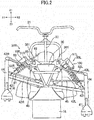
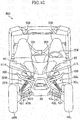
- FIG. 2 is a front view of the snowmobile 1.
- illustration of a front cover 9 configured to cover a front part of the snowmobile 1 is omitted.
- a direction indicated by the arrow Y1 is referred to as "forward direction”.
- a direction indicated by the arrow Y2 is referred to as "rearward direction”.
- a side indicated by the arrow Y1 is referred to as "front side” and a side indicated by the arrow Y2 is referred to as "rear side” in FIG. 1 and FIG. 2 .
- a direction indicated by the arrow Z1 is referred to as "upward direction”.
- a direction indicated by the arrow Z2 is referred to as “downward direction”.
- a side indicated by the arrow Z1 is referred to as “upper side” and a side indicated by the arrow Z2 is referred to as “lower side”.
- a direction indicated by the arrow X1 is referred to as "right-hand direction”.
- a direction indicated by the arrow X2 is referred to as "left-hand direction”.
- a side indicated by the arrow X1 is referred to as “right side” and a side indicated by the arrow X2 is referred to as "left side”.
- the snowmobile 1 includes a right ski 41 R arranged on the right of a vehicle body frame 30 and a left ski 41L arranged on the left of the vehicle body frame 30 as grounded portions.
- the right ski 41 R is supported by a lower arm 42R and an upper arm 43R.
- the left ski 41 L is supported by a lower arm 42L and an upper arm 43L.
- the right lower arm 42R and the right upper arm 43R extend in the right-hand direction from base portions thereof coupled to the vehicle body frame 30 so as to be coupled to a knuckle 44 having a lower end coupled to the right ski 41R.
- the left lower arm 42L and the left upper arm 43L extend in the left-hand direction from base portions thereof coupled to the vehicle body frame 30 so as to be coupled to another knuckle 44 having a lower end coupled to the left ski 41 L.
- the base portions of the arms 42R, 43R, 42L, and 43L are coupled to the vehicle body frame 30 so as to be rotatable. As a result, the skis 41R and 41L are vertically movable relative to the vehicle body frame 30.
- the snowmobile 1 includes shock absorbers 50R and 50L (hereinafter also collectively referred to as "shock absorbers 50") according to the embodiment.
- the right shock absorber 50R includes a right damper 51 R and a right spring 52R.
- the left shock absorber 50L includes a left damper 51L and a left spring 52L.
- One end of each of the dampers 51 R and 51 L (hereinafter also collectively referred to as "dampers 51”) is coupled to a corresponding one of brackets 301 provided to the vehicle body frame 30, whereas another end of each of the dampers 51 R and 51 L is coupled to a corresponding one of brackets 421 provided to the lower arms 42R and 42L, respectively.
- the springs 52R and 52L are, for example, coil springs, and exhibit spring forces in accordance with extension and contraction of the dampers 51 R and 51L. A detailed configuration of each of the shock absorbers 50R and 50L is described later.
- the snowmobile 1 includes an engine 11 and a transmission 12 as a drive system.
- the engine 11 includes a crank case 11d configured to accommodate a crankshaft (not shown) therein, a cylinder block 11b mounted to the crank case 11d, and a cylinder head 11c mounted to the cylinder block 11b.
- a cylinder is formed inside the cylinder block 11b.
- An intake passage and an exhaust passage being in communication with a combustion chamber of the cylinder are formed inside the cylinder head 11c.
- the crank case 11d is positioned on the rear side of the arms 42R and 43R configured to support the ski 41R and the arms 42L and 43L configured to support the ski 41L on a side view of a vehicle body.
- the cylinder block 11b and the cylinder head 11c are arranged so that an axis of the cylinder is inclined rearward with respect to the engine 11.
- a posture of the engine 11 is not limited to an illustrated example.
- the transmission 12 is, for example, a continuously variable transmission, and includes a drive pulley 12a configured to receive a torque from the crankshaft and a driven pulley 12b configured to receive the torque from the drive pulley 12a.
- a belt configured to transfer the torque of the drive pulley 12a to the driven pulley 12b is looped around the drive pulley 12a and the driven pulley 12b.
- the drive pulley 12a is provided to, for example, an end portion of the crankshaft.
- the driven pulley 12b is provided to, for example, a secondary shaft (not shown) which is positioned on the rear side of the crankshaft and at a higher position than a position of the crankshaft.
- the transmission 12 is not necessarily required to be the continuously variable transmission, and may be, for example, a gear type one including a gear having a plurality of gear positions.
- the snowmobile 1 includes a track belt drive shaft 14 provided with a sprocket configured to mesh with a track belt 16.
- the track belt drive shaft 14 is coupled to the secondary shaft via a belt, a chain, or the like to receive the torque of the engine 11 through the transmission 12.
- Guide wheels 15a, 15b, and 15c, a slide rail 17, a link structure 18, and a shock absorber 19 are arranged inside the track belt 16.
- the guide wheels 15a, 15b, and 15c, and the slide rail 17 are configured to guide the track belt 16.
- the link structure 18 and the shock absorber 19 are provided between the guide wheel 15c supported on the vehicle body frame 30 and the slide rail 17.
- the slide rail 17 configured to guide the track belt 16 is vertically movable relative to the vehicle body frame 30 through the link structure 18.
- the shock absorber 19 is arranged between the vehicle body frame 30 and the track belt 16.
- the snowmobile 1 has a seat 8 for a driver to sit in.
- the seat 8 is arranged above the track belt 16.
- a steering handle 21 configured to steer the skis 41 R and 41 L is arranged.
- the steering handle 21 is mounted to a top of a steering column 22.
- the steering column 22 extends downward and obliquely to the front side from a central portion of the steering handle 21.
- the steering handle 21 is coupled to the skis 41R and 41L through intermediation of the steering column 22 and tie rods 45 (see FIG. 2 ).
- the shock absorber 50 is a shock absorber in which a force generated by a hydraulic pressure is exerted in a contraction direction, as described later.
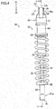
- FIG. 3 is a front view of the shock absorber 50
- FIG. 4 is a side view of the shock absorber 50.
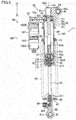
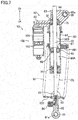
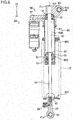
- FIG. 5 and FIG. 6 are sectional views of the shock absorber 50 when the shock absorber 50 is cut along the line V-V of FIG. 4 through an axis CA of the cylinder 60.
- FIG. 5 is the sectional view for illustrating a state in which the shock absorber 50 is most extended
- FIG. 6 is the sectional view for illustrating a state in which the shock absorber 50 is most contracted.
- a direction indicated by the arrow Z3 and a direction indicated by the arrow Z4 which are parallel to the axis CA of the cylinder 60 are referred to as “upward direction” and “downward direction”, respectively, and a side indicated by the arrow Z3 and a side indicated by the arrow Z4 are referred to as “upper side” and “lower side”, respectively.
- the upward direction, the downward direction, the upper side, and the lower side for the shock absorber 50 correspond to the upward direction, the downward direction, the upper side, and the lower side for the snowmobile 1, respectively.
- the damper 51 of the shock absorber 50 includes a cylinder 60 having a cylindrical shape, a piston 65, a first rod (main rod) 61, and a second rod (sub-rod) 62.
- the cylinder 60 is filled with oil.
- the piston 65 is slidable in a vertical direction inside the cylinder 60.
- the first rod 61 extends downward with respect to the piston 65.
- the second rod 62 extends upward with respect to the piston 65.
- a rod mounting member 81 to be mounted to one of two targets of damping is provided to a lower end portion of the first rod 61, whereas a cylinder mounting member 95 to be mounted to another of the two targets is provided to an upper end portion of the cylinder 60.
- the spring 52 is expanded and contracted in accordance with relative movement between the rod mounting member 81 and the cylinder mounting member 95.
- the cylinder 60 includes a cylinder tube 64 having a cylindrical shape, a first rod guide 70, and a second rod guide 75.
- the first rod guide 70 is provided to a lower end portion of the cylinder tube 64 and is configured to allow the first rod 61 to pass therethrough.
- the second rod guide 75 is provided to an upper end portion of the cylinder tube 64 and is configured to allow the second rod 62 to pass therethrough.
- the first rod guide 70 is fitted into the lower end portion of the cylinder tube 64.
- the first rod guide 70 includes a guide main body 71 having an approximately hollow cylindrical shape, a lid body 72, an oil seal 73, and a rubber member 74.
- the lid body 72 is positioned below the guide main body 71.
- the oil seal 73 is provided between the first rod 61 and the guide main body 71.
- the rubber member 74 is mounted to a top of the guide main body 71.
- the lid body 72 is configured to close a lower end opening of the cylinder tube 64 and is fixed to the guide main body 71 with a screw.
- the rubber member 74 comes into abutment against a stopper 66 described later when the shock absorber 50 is most extended (see FIG. 5 ).
- the second rod guide 75 is fitted into a cap member 90 mounted to the upper end portion of the cylinder tube 64 and is arranged so as to close an upper end opening of the cylinder tube 64.
- the second rod guide 75 includes a guide main body 76 having an approximately hollow cylindrical shape, a plate member 77 having an annular shape, an oil seal 78, and a plate member 79 having an annular shape.
- the plate member 77 is positioned above the guide main body 76.
- the oil seal 78 is provided between the second rod 62 and the guide main body 76.
- the plate member 79 is mounted to a lower portion of the guide main body 76. The plate member 79 comes into abutment against a stopper 67 described later when the shock absorber 50 is most contracted (see FIG. 6 ).
- An outer diameter of the lower portion of the guide main body 76 is smaller than a diameter of the upper end opening of the cylinder tube 64.
- a gap 759 is formed between the upper end of the cylinder tube 64 and the second rod guide 75.
- a space inside the cylinder 60 is brought into communication with a pressurizing mechanism 100 described later through the gap 759.
- the piston 65 is arranged so as to be slidable in the vertical direction being an axial direction of the cylinder 60 between the first rod guide 70 and the second rod guide 75 inside the cylinder tube 64.
- the piston 65 partitions a space inside the cylinder tube 64 between the first rod guide 70 and the second rod guide 75, which is filled with oil, into a first oil chamber 60A and a second oil chamber 60B.
- the first oil chamber 60A is a space between the piston 65 and the first rod guide 70
- the second oil chamber 60B is a space between the piston 65 and the second rod guide 75.
- communication paths 65a configured to bring the first oil chamber 60A and the second oil chamber 60B into communication with each other are formed in the piston 65.
- the shock absorber 50 is extended, specifically, when the piston 65 is moved downward, the oil is moved from the first oil chamber 60A into the second oil chamber 60B through the communication paths 65a.
- the shock absorber 50 is contracted, specifically, when the piston 65 is moved upward, the oil is moved from the second oil chamber 60B into the first oil chamber 60A through the communication paths 65a.
- the first rod 61 is provided to extend below the piston 65, whereas the second rod 62 having a larger diameter than that of the first rod 61 is provided to extend above the piston 65.
- the first rod 61 extends downward from the piston 65 and passes through the first oil chamber 60A so as to slidably pass through the first rod guide 70 to project externally from the cylinder 60.
- the second rod 62 extends upward from the piston 65 and passes through the second oil chamber 60B so as to slidably pass through the second rod guide 75.
- the second rod 62 projects from the second rod guide 75 to outside of the cylinder 60.
- the cap member 90 has a cylinder portion 93 having a cylindrical shape.
- the cylinder portion 93 is formed above a main body portion 91 which is configured to accommodate the second rod guide 75 therein and is mounted to the upper end portion of the cylinder tube 64, and has a through hole 93a passing in the vertical direction.
- the second rod 62 passes through the through hole 93a of the cylinder portion 93 to project externally from the cylinder 60 and also from the cap member 90.
- the stopper 66 having an annular plate shape is provided at a position slightly down away from the piston 65.
- the stopper 66 comes into abutment against the rubber member 74 of the first rod guide 70 when the shock absorber 50 is most extended, specifically, when the piston 65 is positioned at the lowermost position (see FIG. 5 ).
- the stopper 67 having an annular plate shape is also provided at a position slightly up away from the piston 65. The stopper 67 comes into abutment with the plate member 79 of the second rod guide 75 when the shock absorber 50 is most contracted, specifically, when the piston 65 is positioned at an uppermost position (see FIG. 6 ).
- an upper end portion of the first rod 61 passes through the piston 65 to be located above the piston 65 so as to be forced into a lower end portion of the second rod 62 having a larger diameter than that of the first rod 61.
- the stopper 66 is fitted over an outer periphery of the first rod 61 so as to be opposed to a lower surface of the piston 65.
- the stopper 67 is fitted over an outer periphery of the first rod 61 so as to be opposed to an upper surface of the piston 65 to come into abutment against a lower surface of the second rod 62.
- a sub-communication path 61 a configured to bring the communication paths 65a of the piston 65 and the first oil chamber 60A into communication with each other is formed in the first rod 61.
- a needle valve 612 configured to adjust an opening degree of the sub-communication path 61a to increase or decrease the damping force is accommodated inside the first rod 61.
- the damper 51 of the shock absorber 50 further includes the pressurizing mechanism 100 configured to pressurize the oil filling a space inside the cylinder 60.
- the pressurizing mechanism 100 includes a cylinder 101 having a cylindrical shape and a piston 102.
- the cylinder 101 has the vertical direction as an axial direction.
- the piston 102 is slidable in the vertical direction inside the cylinder 101.
- the piston 102 partitions a space inside the cylinder 101 into a gas chamber 100A and an oil chamber 100B.
- the gas chamber 100A is filled with a high-pressure gas, whereas the oil chamber 100B is in communication with the cylinder 60 and is filled with the oil.
- the pressurizing mechanism 100 is mounted to the cap member 90 mounted to the upper end portion of the cylinder tube 64.
- the cap member 90 includes a pressurizing-mechanism mounting portion 92 extending radially from the main body portion 91 mounted to the upper end portion of the cylinder tube 64.
- the pressurizing mechanism 100 is coupled to a lower surface of the pressurizing-mechanism mounting portion 92.
- a communication path 92a configured to bring the cylinder 60 of the damper 51 and the cylinder 101 of the pressurizing mechanism 100 into communication with each other is formed in the pressurizing-mechanism mounting portion 92.
- the communication path 92a is brought into communication with the space inside the cylinder 60 through the gap 759 formed between the upper end of the cylinder tube 64 and the second rod guide 75.
- a pressure applied to the oil in the oil chamber 100B from the piston 102 through the high-pressure gas enclosed within the gas chamber 100A of the cylinder 101 is transferred to the oil inside the cylinder 60 of the damper 51 through the communication path 92a formed in the pressurizing-mechanism mounting portion 92.
- the second rod 62 positioned on the upper side is formed to have a larger diameter than that of the first rod 61 positioned on the lower side, as described above.
- the force generated by the hydraulic pressure is exerted upward at a boundary portion between the first rod 61 and the second rod 62.
- the stopper 67 is arranged at the boundary between the first rod 61 and the second rod 62.
- An area of an upper pressure-receiving surface of the stopper 67 is smaller than an area of a lower pressure-receiving surface of the stopper 67.
- a member arranged at the boundary between the first rod 61 and the second rod 62 is not limited to the stopper 67, and may be the piston 65 or the stopper 66.
- the force generated by the hydraulic pressure is exerted upward on the stopper 67, the first rod 61 coupled thereto, and the like, as described above.
- the piston 102 of the pressurizing mechanism 100 is also moved upward, that is, in a direction in which the oil is pressurized (see FIG. 6 ).
- the shock absorber 50 is extended to move the first rod 61 downward, the piston 102 of the pressurizing mechanism 100 is also moved downward (see FIG. 5 ).
- a rod-end coupling member 80 which extends in the vertical direction is mounted to the lower end portion of the first rod 61. Specifically, the lower end portion of the first rod 61 is forced into an upper end portion of the rod-end coupling member 80.
- the rod mounting member 81 is mounted to a lower end portion of the rod-end coupling member 80.
- a through hole 81a passing in a front-and-rear direction is formed in the rod mounting member 81.
- a flange portion 82 is provided to an upper end portion of the rod-end coupling member 80.
- a spring seat 83 is provided to the flange portion 82.
- a spring seat 69 is provided to a middle portion of the cylinder tube 64.
- the spring 52 is supported between the spring seat 69 provided to the cylinder tube 64 and the spring seat 83 provided to the rod-end coupling member 80.
- the spring 52 is arranged along the axis CA of the cylinder 60 so as to surround the cylinder 60 and the first rod 61.
- An adjuster 84 configured to adjust the damping force is provided to a middle portion of the rod-end coupling member 80.
- the adjuster 84 radially moves an adjusting element 841 provided inside the rod-end coupling member 80 so as to vertically move an inner rod 611 provided inside the first rod 61.
- the needle valve 612 arranged above the inner rod 611 is also vertically moved. As a result, an opening degree of the sub-communication path 61a is adjusted by the needle valve 612.
- the cylinder mounting member 95 is provided to the cap member 90 mounted to the upper end portion of the cylinder tube 64.
- a through hole 95a passing in the front-and-rear direction is formed in the cylinder mounting member 95.
- the through hole 81a formed in the rod mounting member 81 and the through hole 95a formed in the cylinder mounting member 95 are oriented in the same direction so as to enable rocking of the shock absorber 50.
- the cylinder mounting member 95 is arranged so as to be offset from the axis CA of the cylinder 60.
- the cylinder mounting member 95 is provided on a radially outer side of the cylinder 60 with respect to the axis CA of the cylinder 60.
- the cylinder mounting member 95 is provided on the radially outer side of the cylinder 60 as compared to the second rod 62 so as not to interfere with the second rod 62.
- the cylinder mounting member 95 is arranged on the radially outer side of the cylinder 60 as compared to the cylinder 60.
- the cylinder mounting member 95 is arranged below a position FE of the upper end of the second rod 62 when the shock absorber 50 is most contracted (see FIG. 6 ). Further, the cylinder mounting member 95 is arranged below a center position HE of the second rod 62 in the vertical direction when the shock absorber 50 is most contracted. Meanwhile, the cylinder mounting member 95 is arranged above the second rod guide 75 that is provided to the upper end portion of the cylinder 60. Further, the cylinder mounting member 95 is arranged above the upper end of the second rod 62 when the shock absorber 50 is most extended (see FIG. 5 ).
- the cylinder mounting member 95 is offset from the axis CA of the cylinder 60 in a direction opposite to a side to which the pressurizing mechanism 100 is provided. Further, the cylinder mounting member 95 is provided at a position away from the cylinder portion 93 of the cap member 90 in the radial direction.
- the cap member 90 has a support portion 94 extending radially from the cylinder portion 93.
- the cylinder mounting member 95 is provided to a distal end portion of the support portion 94.
- the cylinder mounting member 95 is provided below an upper end of the cylinder portion 93.
- the axis CA of the cylinder 60 and an axis BB passing through the through hole 95a in the cylinder mounting member 95 are skew lines not intersecting with each other or being parallel to each other in a three-dimensional space.
- the axis CA of the cylinder 60 and the axis BB passing through the through hole 95a of the cylinder mounting member 95 are radially away from each other, and thus do not intersect with each other.
- the axis CA of the cylinder 60 extends in the vertical direction
- the axis BB passing through the through hole 95a of the cylinder mounting member 95 extends in the front-and-rear direction. Therefore, the axis CA and the axis BB are not parallel to each other either.
- the rod mounting member 81 of the shock absorber 50 is coupled to the bracket 421 provided to each of the lower arms 42R and 42L of the snowmobile 1.
- the cylinder mounting member 95 of the shock absorber 50 is coupled to each of the brackets 301 provided to the vehicle body frame 30 of the snowmobile 1.
- the cylinder mounting member 95 is positioned on an inner side of the cylinder 60 in a vehicle width direction.
- the cylinder mounting member 95 may be positioned on an outer side of the cylinder 60 in the vehicle width direction.
- the target member to which the rod mounting member 81 is coupled and the target member to which the cylinder mounting member 95 is coupled may be interchanged.
- the rod mounting member 81 may be coupled to a corresponding one of the brackets 301 so as to be positioned on an upper side, whereas the cylinder mounting member 95 may be coupled to a corresponding one of the brackets 421 so as to be positioned on a lower side.
- FIG. 2 a state in which the right ski 41R is subjected to a larger reaction force from a snow surface than a reaction force to which the left ski 41 L is subjected so that the right shock absorber 50R is more contracted than the left shock absorber 50L is illustrated. Therefore, the second rod 62 projects externally from the cap member 90 of the right shock absorber 50R.
- the cylinder mounting member 95 is arranged so as to be offset from the axis CA of the cylinder 60, as illustrated in FIG. 3 , FIG. 5 , and FIG. 6 . More specifically, the cylinder mounting member 95 is arranged on the radially outer side of the cylinder 60 as compared to the second rod 62, and also is arranged on the radially outer side of the cylinder 60 as compared to the cylinder 60. With this arrangement, the degree of freedom of the position of the cylinder mounting member 95 along the axial direction (vertical direction) of the cylinder 60 can be increased while ensuring a movable range of the second rod 62.
- the cylinder mounting member 95 is arranged so as to be located on an axially inner (lower) side of an outer (upper) axial end of the second rod 62 when the shock absorber 50 is most contracted, as illustrated in FIG. 6 .
- an interval between the rod mounting member 81 and the cylinder mounting member 95 can be reduced as compared to a case without the above-mentioned characteristic.
- the cylinder mounting member 95 is arranged on an axially outer (upper) side of the second rod guide 75, as illustrated in FIG. 5 and FIG. 6 .
- an increase in angle formed between a straight line connecting the rod mounting member 81 and the cylinder mounting member 95 and the axis CA of the cylinder 60 can be suppressed as compared to the case without the above-mentioned characteristic.
- the cylinder mounting member 95 can be arranged closer to the second rod 62. As a result, a stress exerted on the support portion 94 configured to support the cylinder mounting member 95 in a cantilever fashion can be reduced.
- the cylinder mounting member 95 is provided on the radially outer side of the cylinder 60 with respect to the cylinder portion 93 of the cap member 90 mounted to the end portion of the cylinder tube 64, as illustrated in FIG. 5 and FIG. 6 .
- a length of the supporting portion 94 configured to support the cylinder mounting member 95 in a cantilever fashion can be reduced as compared to the case without the above-mentioned characteristic.
- strength against the stress exerted on the supporting portion 94 can be improved.
- the axis CA of the cylinder 60 and the axis BB passing through the through hole 95a formed in the cylinder mounting member 95 are skew lines not intersecting with each other or being parallel to each other, as illustrated in FIG. 5 and FIG. 6 .
- the second rod guide 75 is provided to the end portion of the cylinder tube 64, and the second rod 62 projects from the second rod guide 75 to outside of the cylinder tube 64, as illustrated in FIG. 5 and FIG. 6 .
- a length of the cylinder tube 64 can be reduced as compared to the case without the above-mentioned characteristic, which can eventually reduce a total length of the shock absorber 50.
- the pressurizing mechanism 100 is arranged outside of the cylinder tube 64, as illustrated in FIG. 5 and FIG. 6 .
- the length of the cylinder tube 64 can be reduced as compared to the case without the above-mentioned characteristic, which can eventually reduce the total length of the shock absorber 50.
- the cylinder mounting member 95 is provided on the side opposite to the side to which the pressurizing member 100 is provided, with respect to the axis CA of the cylinder 60, as illustrated in FIG. 5 and FIG. 6 .
- inhibition of the coupling of the cylinder mounting member 95 by the pressurizing mechanism 100 can be suppressed so as to improve ease of layout of the shock absorber 50 as compared to the case without the above-mentioned characteristic.
- the spring 52 is arranged so as to be inclined with respect to the straight line connecting the rod mounting member 81 and the cylinder mounting member 95 along the axis CA of the cylinder 60, as illustrated in FIG. 5 and FIG. 6 .
- a spring force of the spring 52 can be more directly exhibited for the extension and contraction of the damper 51.
- the arrangement of the spring 52 is not limited to the above-mentioned case.
- the spring 52 may be arranged so as to be inclined with respect to the axis CA of the cylinder 60.
- an upper spring seat 691 provided to the cylinder tube 64 is formed to extend in an offset direction of the cylinder mounting member 95
- a lower spring seat 831 provided to the rod-end coupling member 80 is formed to extend in a direction opposite to the offset direction.
- the spring 52 is arranged along a straight line CL connecting the rod mounting member 81 and the cylinder mounting member 95 when the piston 65 is located in the middle of the cylinder 60, for example, when the shock absorber 50 is compressed by about 1/3 from a most extended state. With this arrangement, a bending force applied to the first rod 61 as a result of the compression of the spring 52 can be reduced.
- the spring 52 may be arranged so as to be offset from the axis CA of the cylinder 60.
- the spring 52 is offset to the same direction in which the cylinder mounting member 95 is offset with respect to the axis CA of the cylinder 60, while being arranged along the axis CA of the cylinder 60.
- a spring seat 693 provided to the cylinder tube 64 and a spring seat 833 provided to the rod-end coupling member 80 are formed to extend in the offset direction of the cylinder mounting member 95.
- the rod mounting members 81 of the shock absorbers 50 are mounted to the lower arms 42R and 42L of the snowmobile 1, respectively, whereas the cylinder mounting members 95 of the shock absorbers 50 are mounted to the vehicle body frame 30 of the snowmobile 1, as illustrated in FIG. 2 .
- the second rods 62 project upward. Thus, it is not necessary to take a clearance between each of the second rods 62 and the ground surface into consideration.
- each of the cylinder mounting members 95 is positioned on the inner side of the cylinder 60 in the vehicle width direction, as illustrated in FIG. 2 .
- the cylinder mounting members 95 are offset in a direction toward the vehicle body.
- the shock absorber according to the present application is not limited to the embodiment described above.
- the length of the cylinder tube may be set long and the second rod guide may be provided in the middle of the cylinder tube so that the second rod (sub-rod) is movable only on the inner side of the cylinder tube.
- the pressurizing mechanism including the spring may be provided on the inner side of the cylinder tube.
- the shock absorber according to the embodiment may be applied to the shock absorber 19 (see FIG. 1 ) arranged inside of the track belt 16.
- FIG. 9 is a front view of a vehicle 200
- FIG. 10 is a front view of a vehicle 300, to each of which the above-mentioned shock absorbers 50R and 50L are applied.
- the vehicle 200 illustrated in FIG. 9 is a saddle type four-wheeled vehicle called an "all-terrain vehicle (ATV)", which includes a steering bar 201.
- the vehicle 300 illustrated in FIG. 10 is a four-wheeled vehicle called a "recreational off-highway vehicle (ROV)", which includes a plurality of seats 308 arranged in the vehicle width direction and a steering wheel 309.
- ATV all-terrain vehicle
- ROV return off-highway vehicle
- each of the vehicles 200 and 300 has front wheels 46R and 46L arranged on both the right and left of the front part of the vehicle body frame 30 as grounded portions.
- the right front wheel 46R is supported by the lower arm 42R and the upper arm 43R
- the left front wheel 46L is supported by the lower arm 42L and the upper arm 43L.
- the base portions of the arms 42R, 43R, 42L, and 43L are coupled to the vehicle body frame 30 so as to be rotatable.
- the front wheels 46R and 46L are vertically movable relative to the vehicle body frame 30.
- Each of the vehicles 200 and 300 includes the shock absorbers 50R and 50L.
- the shock absorber 50R includes the damper 51 R and the spring 52R
- the shock absorber 50L includes the damper 51L and the spring 52L.
- the rod mounting members 81 provided to lower portions of the shock absorbers 50R and 50L are coupled to the brackets 421 provided to the lower arms 42R and 42L in the vehicle 200 and are coupled to the brackets 421 provided to the upper arms 43R and 43L in the vehicle 300.
- the cylinder mounting members 95 provided to the upper portions of the shock absorbers 50 are coupled to the brackets 301 provided to the vehicle body frame 30.
- the shock absorbers 50R and 50L are used not only to suspend the front wheels 46R and 46L but may also be used to suspend rear wheels (not shown).
Landscapes
- Engineering & Computer Science (AREA)
- General Engineering & Computer Science (AREA)
- Mechanical Engineering (AREA)
- Vehicle Body Suspensions (AREA)
- Fluid-Damping Devices (AREA)
- Axle Suspensions And Sidecars For Cycles (AREA)
Abstract
Description
- The present invention relates to a shock absorber, a vehicle, and a snowmobile.
- In general, in a shock absorber for a vehicle, one rod coupled to a piston provided inside a cylinder extends externally from one end portion of the cylinder. Oil filling the cylinder is pressurized by a high-pressure gas, a spring, or the like. With this structure, a force is exerted on the rod in a direction in which the rod projects from the cylinder by a pressure received by the piston from the oil. Specifically, the force generated by a hydraulic pressure is exerted on the shock absorber in an extension direction.
- The shock absorber in which the force generated by the hydraulic pressure is exerted in the extension direction as described above may not sufficiently absorb a shock received from a ground surface, resulting in a fear of adversely affecting riding comfort of a vehicle. Further, timing of a load shift to an outer wheel or ski is likely to be advanced at cornering, also resulting in the fear of adversely affecting the riding comfort of the vehicle.
- To cope with the adverse effect described above, the following is disclosed in Japanese Patent Application Laid-open No.
2010-96347 - The shock absorber in which the force generated by the hydraulic pressure is exerted in the contraction direction as described above can solve the problem of the above-mentioned shock absorber in which the force generated by the hydraulic pressure is exerted in the extension direction so as to improve the riding comfort of the vehicle.
- In the shock absorber in which the force generated by the hydraulic pressure is exerted in the contraction direction, however, a movable range is required to be ensured for the two rods. Therefore, the shock absorber cannot be prevented from being increased in length and size, and has a problem in ease of layout. In the shock absorber disclosed in Japanese Patent Application Laid-open No.
2010-96347 - In particular, the shock absorber to be applied to a vehicle for running on an irregular ground, such as a recreational off-highway vehicle (ROV) or a snowmobile, is required to ensure ability to absorb the shock. Thus, it is difficult to reduce a rod length and a cylinder size.
- It is an object of the present invention to provide a shock absorber, a vehicle, and a snowmobile, which are capable of improving ease of layout of the shock absorber in which a force generated by a hydraulic pressure is exerted in a contraction direction.
- According to the present invention said object is solved by a shock absorber having the features of independent claim 1 and by a vehicle and a snowmobile having at least one of such shock absorber. Preferred embodiments are laid down in the dependent claims.
- According to one embodiment of the present application, a shock absorber includes a cylinder, a piston, which is configured to partition an internal space of the cylinder into two oil chambers, and is capable of sliding in an axial direction of the cylinder, the piston having formed therethrough a communication path configured to bring the two oil chambers into communication with each other, a first rod, which extends in a first direction of the axial direction with respect to the piston, a first rod guide, which is provided to the cylinder, and through which the first rod passes, a second rod, which has a diameter larger than a diameter of the first rod, and extends in a second direction of the axial direction, which is opposite to the first direction, with respect to the piston, a second rod guide, which is provided to the cylinder, and through which the second rod passes, a pressurizing mechanism, which is configured to pressurize oil filling the internal space of the cylinder, a rod mounting member, which is provided to the first rod outside of the cylinder, a cylinder mounting member, which is provided to the cylinder outside of the cylinder, and a spring, which is configured to be expanded and contracted in accordance with relative movement between the rod mounting member and the cylinder mounting member. The cylinder mounting member is arranged so as to be offset from an axis of the cylinder.
- Further, according to another embodiment of the present application, a vehicle includes the shock absorber.
- According to the shock absorber described above, the cylinder mounting member is arranged so as to be offset from the axis of the cylinder. Hence, an interval between the rod mounting member and the cylinder mounting member can be reduced while ensuring the movable range of the second rod. In this manner, the ease of layout of the shock absorber can be improved.
-
-
FIG. 1 is a side view of a snowmobile according to an embodiment of the present application. -
FIG. 2 is a front view of the snowmobile illustrated inFIG. 1 . -
FIG. 3 is a front view of a shock absorber according to the embodiment. -
FIG. 4 is a side view of the shock absorber illustrated inFIG. 3 . -
FIG. 5 is a sectional view of the shock absorber illustrated inFIG. 3 . -
FIG. 6 is another sectional view of the shock absorber illustrated inFIG. 3 . -
FIG. 7 is a sectional view of a shock absorber according to a modification example. -
FIG. 8 is a sectional view of a shock absorber according to another modification example. -
FIG. 9 is a front view of a vehicle according to the embodiment. -
FIG. 10 is a front view of another vehicle according to the embodiment. - The terminology used herein is for the purpose of describing particular embodiments. As used herein, the term "and/or" includes any and all combinations of one or more of the associated listed items. As used herein, the singular forms "a," "an," and "the" are intended to include the plural forms as well as the singular forms, unless the context clearly indicates otherwise. It will be further understood that the terms "comprises" and/or "comprising," when used in this specification, specify the presence of stated features, steps, operations, elements, and/or components, but do not preclude the presence or addition of one or more other features, steps, operations, elements, components, and/or groups thereof.
- Unless otherwise defined, all terms (including technical and scientific terms) used herein have the same meaning as commonly understood by one having ordinary skill in the art to which this teaching belongs. It will be further understood that terms, such as those defined in commonly used dictionaries, should be interpreted as having a meaning that is consistent with their meaning in the context of the relevant art and the present disclosure and will not be interpreted in an idealized or overly formal sense unless expressly so defined herein.
- In describing the present teaching, it will be understood that a number of techniques and steps are disclosed. Each of these has individual benefit and each can also be used in conjunction with one or more, or in some cases all, of the other disclosed techniques. Accordingly, for the sake of clarity, this description will refrain from repeating every possible combination of the individual steps in an unnecessary fashion.
- In the following description, for purposes of explanation, numerous specific details are set forth in order to provide a thorough understanding of the present teaching. It will be evident, however, to one skilled in the art that the present teaching may be practiced without these specific details.
- The present disclosure is to be considered as an exemplification of the present teaching.
- The present teaching will now be described by referencing the appended figures representing embodiments.
-
FIG. 1 is a side view of a snowmobile 1 according to an embodiment of the present application, andFIG. 2 is a front view of the snowmobile 1. InFIG. 2 , illustration of a front cover 9 (seeFIG. 1 ) configured to cover a front part of the snowmobile 1 is omitted. In the following description, a direction indicated by the arrow Y1 is referred to as "forward direction". A direction indicated by the arrow Y2 is referred to as "rearward direction". A side indicated by the arrow Y1 is referred to as "front side" and a side indicated by the arrow Y2 is referred to as "rear side" inFIG. 1 andFIG. 2 . Similarly, a direction indicated by the arrow Z1 is referred to as "upward direction". A direction indicated by the arrow Z2 is referred to as "downward direction". A side indicated by the arrow Z1 is referred to as "upper side" and a side indicated by the arrow Z2 is referred to as "lower side". A direction indicated by the arrow X1 is referred to as "right-hand direction". A direction indicated by the arrow X2 is referred to as "left-hand direction". A side indicated by the arrow X1 is referred to as "right side" and a side indicated by the arrow X2 is referred to as "left side". - As illustrated in
FIG. 2 , the snowmobile 1 includes a right ski 41 R arranged on the right of avehicle body frame 30 and aleft ski 41L arranged on the left of thevehicle body frame 30 as grounded portions. The right ski 41 R is supported by alower arm 42R and anupper arm 43R. Similarly, theleft ski 41 L is supported by alower arm 42L and anupper arm 43L. The rightlower arm 42R and the rightupper arm 43R extend in the right-hand direction from base portions thereof coupled to thevehicle body frame 30 so as to be coupled to aknuckle 44 having a lower end coupled to the right ski 41R. The leftlower arm 42L and the leftupper arm 43L extend in the left-hand direction from base portions thereof coupled to thevehicle body frame 30 so as to be coupled to anotherknuckle 44 having a lower end coupled to the left ski 41 L. The base portions of thearms vehicle body frame 30 so as to be rotatable. As a result, theskis 41R and 41L are vertically movable relative to thevehicle body frame 30. - The snowmobile 1 includes
shock absorbers shock absorbers 50") according to the embodiment. Theright shock absorber 50R includes aright damper 51 R and aright spring 52R. Theleft shock absorber 50L includes aleft damper 51L and aleft spring 52L. One end of each of thedampers dampers 51") is coupled to a corresponding one ofbrackets 301 provided to thevehicle body frame 30, whereas another end of each of thedampers brackets 421 provided to thelower arms springs dampers shock absorbers - As illustrated in
FIG. 1 , the snowmobile 1 includes anengine 11 and atransmission 12 as a drive system. Theengine 11 includes a crankcase 11d configured to accommodate a crankshaft (not shown) therein, acylinder block 11b mounted to the crankcase 11d, and a cylinder head 11c mounted to thecylinder block 11b. A cylinder is formed inside thecylinder block 11b. An intake passage and an exhaust passage being in communication with a combustion chamber of the cylinder are formed inside the cylinder head 11c. The crankcase 11d is positioned on the rear side of thearms arms ski 41L on a side view of a vehicle body. Thecylinder block 11b and the cylinder head 11c are arranged so that an axis of the cylinder is inclined rearward with respect to theengine 11. A posture of theengine 11 is not limited to an illustrated example. - The
transmission 12 is, for example, a continuously variable transmission, and includes adrive pulley 12a configured to receive a torque from the crankshaft and a drivenpulley 12b configured to receive the torque from thedrive pulley 12a. A belt configured to transfer the torque of thedrive pulley 12a to the drivenpulley 12b is looped around thedrive pulley 12a and the drivenpulley 12b. Thedrive pulley 12a is provided to, for example, an end portion of the crankshaft. The drivenpulley 12b is provided to, for example, a secondary shaft (not shown) which is positioned on the rear side of the crankshaft and at a higher position than a position of the crankshaft. Thetransmission 12 is not necessarily required to be the continuously variable transmission, and may be, for example, a gear type one including a gear having a plurality of gear positions. - The snowmobile 1 includes a track belt drive shaft 14 provided with a sprocket configured to mesh with a
track belt 16. The track belt drive shaft 14 is coupled to the secondary shaft via a belt, a chain, or the like to receive the torque of theengine 11 through thetransmission 12.Guide wheels slide rail 17, alink structure 18, and ashock absorber 19 are arranged inside thetrack belt 16. Theguide wheels slide rail 17 are configured to guide thetrack belt 16. Thelink structure 18 and theshock absorber 19 are provided between the guide wheel 15c supported on thevehicle body frame 30 and theslide rail 17. Theslide rail 17 configured to guide thetrack belt 16 is vertically movable relative to thevehicle body frame 30 through thelink structure 18. Theshock absorber 19 is arranged between thevehicle body frame 30 and thetrack belt 16. - The snowmobile 1 has a
seat 8 for a driver to sit in. Theseat 8 is arranged above thetrack belt 16. In front of theseat 8, asteering handle 21 configured to steer theskis 41 R and 41 L is arranged. The steering handle 21 is mounted to a top of asteering column 22. Thesteering column 22 extends downward and obliquely to the front side from a central portion of thesteering handle 21. The steering handle 21 is coupled to theskis 41R and 41L through intermediation of thesteering column 22 and tie rods 45 (seeFIG. 2 ). - The
shock absorber 50 according to the embodiment is now described. Theshock absorber 50 is a shock absorber in which a force generated by a hydraulic pressure is exerted in a contraction direction, as described later.FIG. 3 is a front view of theshock absorber 50, andFIG. 4 is a side view of theshock absorber 50.FIG. 5 andFIG. 6 are sectional views of theshock absorber 50 when theshock absorber 50 is cut along the line V-V ofFIG. 4 through an axis CA of thecylinder 60.FIG. 5 is the sectional view for illustrating a state in which theshock absorber 50 is most extended, whereasFIG. 6 is the sectional view for illustrating a state in which theshock absorber 50 is most contracted. - In the following description, a direction indicated by the arrow Z3 and a direction indicated by the arrow Z4 which are parallel to the axis CA of the
cylinder 60 are referred to as "upward direction" and "downward direction", respectively, and a side indicated by the arrow Z3 and a side indicated by the arrow Z4 are referred to as "upper side" and "lower side", respectively. The upward direction, the downward direction, the upper side, and the lower side for theshock absorber 50 correspond to the upward direction, the downward direction, the upper side, and the lower side for the snowmobile 1, respectively. - The
damper 51 of theshock absorber 50 includes acylinder 60 having a cylindrical shape, apiston 65, a first rod (main rod) 61, and a second rod (sub-rod) 62. Thecylinder 60 is filled with oil. Thepiston 65 is slidable in a vertical direction inside thecylinder 60. Thefirst rod 61 extends downward with respect to thepiston 65. Thesecond rod 62 extends upward with respect to thepiston 65. Arod mounting member 81 to be mounted to one of two targets of damping is provided to a lower end portion of thefirst rod 61, whereas acylinder mounting member 95 to be mounted to another of the two targets is provided to an upper end portion of thecylinder 60. Thespring 52 is expanded and contracted in accordance with relative movement between therod mounting member 81 and thecylinder mounting member 95. - The
cylinder 60 includes acylinder tube 64 having a cylindrical shape, afirst rod guide 70, and asecond rod guide 75. Thefirst rod guide 70 is provided to a lower end portion of thecylinder tube 64 and is configured to allow thefirst rod 61 to pass therethrough. Thesecond rod guide 75 is provided to an upper end portion of thecylinder tube 64 and is configured to allow thesecond rod 62 to pass therethrough. Thefirst rod guide 70 is fitted into the lower end portion of thecylinder tube 64. Thefirst rod guide 70 includes a guidemain body 71 having an approximately hollow cylindrical shape, alid body 72, anoil seal 73, and arubber member 74. Thelid body 72 is positioned below the guidemain body 71. Theoil seal 73 is provided between thefirst rod 61 and the guidemain body 71. Therubber member 74 is mounted to a top of the guidemain body 71. Thelid body 72 is configured to close a lower end opening of thecylinder tube 64 and is fixed to the guidemain body 71 with a screw. Therubber member 74 comes into abutment against astopper 66 described later when theshock absorber 50 is most extended (seeFIG. 5 ). - The
second rod guide 75 is fitted into acap member 90 mounted to the upper end portion of thecylinder tube 64 and is arranged so as to close an upper end opening of thecylinder tube 64. Thesecond rod guide 75 includes a guidemain body 76 having an approximately hollow cylindrical shape, a plate member 77 having an annular shape, anoil seal 78, and aplate member 79 having an annular shape. The plate member 77 is positioned above the guidemain body 76. Theoil seal 78 is provided between thesecond rod 62 and the guidemain body 76. Theplate member 79 is mounted to a lower portion of the guidemain body 76. Theplate member 79 comes into abutment against astopper 67 described later when theshock absorber 50 is most contracted (seeFIG. 6 ). An outer diameter of the lower portion of the guidemain body 76 is smaller than a diameter of the upper end opening of thecylinder tube 64. Agap 759 is formed between the upper end of thecylinder tube 64 and thesecond rod guide 75. A space inside thecylinder 60 is brought into communication with apressurizing mechanism 100 described later through thegap 759. - The
piston 65 is arranged so as to be slidable in the vertical direction being an axial direction of thecylinder 60 between thefirst rod guide 70 and thesecond rod guide 75 inside thecylinder tube 64. Thepiston 65 partitions a space inside thecylinder tube 64 between thefirst rod guide 70 and thesecond rod guide 75, which is filled with oil, into afirst oil chamber 60A and asecond oil chamber 60B. Thefirst oil chamber 60A is a space between thepiston 65 and thefirst rod guide 70, whereas thesecond oil chamber 60B is a space between thepiston 65 and thesecond rod guide 75. - Further,
communication paths 65a configured to bring thefirst oil chamber 60A and thesecond oil chamber 60B into communication with each other are formed in thepiston 65. When theshock absorber 50 is extended, specifically, when thepiston 65 is moved downward, the oil is moved from thefirst oil chamber 60A into thesecond oil chamber 60B through thecommunication paths 65a. On the other hand, when theshock absorber 50 is contracted, specifically, when thepiston 65 is moved upward, the oil is moved from thesecond oil chamber 60B into thefirst oil chamber 60A through thecommunication paths 65a. By the movement of the oil through thecommunication paths 65a as described above, a damping force is generated. - The
first rod 61 is provided to extend below thepiston 65, whereas thesecond rod 62 having a larger diameter than that of thefirst rod 61 is provided to extend above thepiston 65. Thefirst rod 61 extends downward from thepiston 65 and passes through thefirst oil chamber 60A so as to slidably pass through thefirst rod guide 70 to project externally from thecylinder 60. A portion of thefirst rod 61, which projects externally from thecylinder 60, becomes longer as thepiston 65 is moved downward, whereas a portion of thefirst rod 61, which is accommodated in thecylinder 60, becomes longer as thepiston 65 is moved upward. - Meanwhile, the
second rod 62 extends upward from thepiston 65 and passes through thesecond oil chamber 60B so as to slidably pass through thesecond rod guide 75. When thepiston 65 is positioned above a lowermost position (seeFIG. 5 ), thesecond rod 62 projects from thesecond rod guide 75 to outside of thecylinder 60. A portion of thesecond rod 62, which is accommodated in thecylinder 60, becomes longer as thepiston 65 is moved downward, whereas a portion of thesecond rod 62, which projects externally from thecylinder 60, becomes longer as thepiston 65 is moved upward. Thecap member 90 has acylinder portion 93 having a cylindrical shape. Thecylinder portion 93 is formed above amain body portion 91 which is configured to accommodate thesecond rod guide 75 therein and is mounted to the upper end portion of thecylinder tube 64, and has a throughhole 93a passing in the vertical direction. Thesecond rod 62 passes through the throughhole 93a of thecylinder portion 93 to project externally from thecylinder 60 and also from thecap member 90. - The
stopper 66 having an annular plate shape is provided at a position slightly down away from thepiston 65. Thestopper 66 comes into abutment against therubber member 74 of thefirst rod guide 70 when theshock absorber 50 is most extended, specifically, when thepiston 65 is positioned at the lowermost position (seeFIG. 5 ). Further, thestopper 67 having an annular plate shape is also provided at a position slightly up away from thepiston 65. Thestopper 67 comes into abutment with theplate member 79 of thesecond rod guide 75 when theshock absorber 50 is most contracted, specifically, when thepiston 65 is positioned at an uppermost position (seeFIG. 6 ). - More specifically, an upper end portion of the
first rod 61 passes through thepiston 65 to be located above thepiston 65 so as to be forced into a lower end portion of thesecond rod 62 having a larger diameter than that of thefirst rod 61. Thestopper 66 is fitted over an outer periphery of thefirst rod 61 so as to be opposed to a lower surface of thepiston 65. Meanwhile, thestopper 67 is fitted over an outer periphery of thefirst rod 61 so as to be opposed to an upper surface of thepiston 65 to come into abutment against a lower surface of thesecond rod 62. Further, asub-communication path 61 a configured to bring thecommunication paths 65a of thepiston 65 and thefirst oil chamber 60A into communication with each other is formed in thefirst rod 61. Aneedle valve 612 configured to adjust an opening degree of thesub-communication path 61a to increase or decrease the damping force is accommodated inside thefirst rod 61. - The
damper 51 of theshock absorber 50 further includes thepressurizing mechanism 100 configured to pressurize the oil filling a space inside thecylinder 60. Thepressurizing mechanism 100 includes acylinder 101 having a cylindrical shape and apiston 102. Thecylinder 101 has the vertical direction as an axial direction. Thepiston 102 is slidable in the vertical direction inside thecylinder 101. Thepiston 102 partitions a space inside thecylinder 101 into agas chamber 100A and anoil chamber 100B. Thegas chamber 100A is filled with a high-pressure gas, whereas theoil chamber 100B is in communication with thecylinder 60 and is filled with the oil. Thepressurizing mechanism 100 is mounted to thecap member 90 mounted to the upper end portion of thecylinder tube 64. - More specifically, the
cap member 90 includes a pressurizing-mechanism mounting portion 92 extending radially from themain body portion 91 mounted to the upper end portion of thecylinder tube 64. Thepressurizing mechanism 100 is coupled to a lower surface of the pressurizing-mechanism mounting portion 92. Acommunication path 92a configured to bring thecylinder 60 of thedamper 51 and thecylinder 101 of thepressurizing mechanism 100 into communication with each other is formed in the pressurizing-mechanism mounting portion 92. Thecommunication path 92a is brought into communication with the space inside thecylinder 60 through thegap 759 formed between the upper end of thecylinder tube 64 and thesecond rod guide 75. A pressure applied to the oil in theoil chamber 100B from thepiston 102 through the high-pressure gas enclosed within thegas chamber 100A of thecylinder 101 is transferred to the oil inside thecylinder 60 of thedamper 51 through thecommunication path 92a formed in the pressurizing-mechanism mounting portion 92. - In the
shock absorber 50 of this embodiment, thesecond rod 62 positioned on the upper side is formed to have a larger diameter than that of thefirst rod 61 positioned on the lower side, as described above. In this case, the force generated by the hydraulic pressure is exerted upward at a boundary portion between thefirst rod 61 and thesecond rod 62. In this embodiment, thestopper 67 is arranged at the boundary between thefirst rod 61 and thesecond rod 62. An area of an upper pressure-receiving surface of thestopper 67 is smaller than an area of a lower pressure-receiving surface of thestopper 67. Hence, the force generated by the hydraulic pressure is exerted upward on thestopper 67. As a result, the force generated by the hydraulic pressure is exerted upward, specifically, in a direction in which thefirst rod 61 is accommodated into thecylinder 60 even on thefirst rod 61 coupled to thestopper 67 and the like. In this manner, the force generated by the hydraulic pressure is exerted on theshock absorber 50 in a contraction direction. A member arranged at the boundary between thefirst rod 61 and thesecond rod 62 is not limited to thestopper 67, and may be thepiston 65 or thestopper 66. - Further, the force generated by the hydraulic pressure is exerted upward on the
stopper 67, thefirst rod 61 coupled thereto, and the like, as described above. Thus, when theshock absorber 50 is contracted to move thefirst rod 61 upward, thepiston 102 of thepressurizing mechanism 100 is also moved upward, that is, in a direction in which the oil is pressurized (seeFIG. 6 ). On the contrary, when theshock absorber 50 is extended to move thefirst rod 61 downward, thepiston 102 of thepressurizing mechanism 100 is also moved downward (seeFIG. 5 ). - A rod-
end coupling member 80 which extends in the vertical direction is mounted to the lower end portion of thefirst rod 61. Specifically, the lower end portion of thefirst rod 61 is forced into an upper end portion of the rod-end coupling member 80. Therod mounting member 81 is mounted to a lower end portion of the rod-end coupling member 80. A throughhole 81a passing in a front-and-rear direction is formed in therod mounting member 81. - A
flange portion 82 is provided to an upper end portion of the rod-end coupling member 80. Aspring seat 83 is provided to theflange portion 82. Aspring seat 69 is provided to a middle portion of thecylinder tube 64. Thespring 52 is supported between thespring seat 69 provided to thecylinder tube 64 and thespring seat 83 provided to the rod-end coupling member 80. Thespring 52 is arranged along the axis CA of thecylinder 60 so as to surround thecylinder 60 and thefirst rod 61. - An
adjuster 84 configured to adjust the damping force is provided to a middle portion of the rod-end coupling member 80. Theadjuster 84 radially moves an adjustingelement 841 provided inside the rod-end coupling member 80 so as to vertically move aninner rod 611 provided inside thefirst rod 61. Along with the vertical movement of theinner rod 611, theneedle valve 612 arranged above theinner rod 611 is also vertically moved. As a result, an opening degree of thesub-communication path 61a is adjusted by theneedle valve 612. - The
cylinder mounting member 95 is provided to thecap member 90 mounted to the upper end portion of thecylinder tube 64. A throughhole 95a passing in the front-and-rear direction is formed in thecylinder mounting member 95. The throughhole 81a formed in therod mounting member 81 and the throughhole 95a formed in thecylinder mounting member 95 are oriented in the same direction so as to enable rocking of theshock absorber 50. - The
cylinder mounting member 95 is arranged so as to be offset from the axis CA of thecylinder 60. In other words, thecylinder mounting member 95 is provided on a radially outer side of thecylinder 60 with respect to the axis CA of thecylinder 60. Specifically, thecylinder mounting member 95 is provided on the radially outer side of thecylinder 60 as compared to thesecond rod 62 so as not to interfere with thesecond rod 62. Further, thecylinder mounting member 95 is arranged on the radially outer side of thecylinder 60 as compared to thecylinder 60. - Further, the
cylinder mounting member 95 is arranged below a position FE of the upper end of thesecond rod 62 when theshock absorber 50 is most contracted (seeFIG. 6 ). Further, thecylinder mounting member 95 is arranged below a center position HE of thesecond rod 62 in the vertical direction when theshock absorber 50 is most contracted. Meanwhile, thecylinder mounting member 95 is arranged above thesecond rod guide 75 that is provided to the upper end portion of thecylinder 60. Further, thecylinder mounting member 95 is arranged above the upper end of thesecond rod 62 when theshock absorber 50 is most extended (seeFIG. 5 ). - Further, the
cylinder mounting member 95 is offset from the axis CA of thecylinder 60 in a direction opposite to a side to which thepressurizing mechanism 100 is provided. Further, thecylinder mounting member 95 is provided at a position away from thecylinder portion 93 of thecap member 90 in the radial direction. Thecap member 90 has asupport portion 94 extending radially from thecylinder portion 93. Thecylinder mounting member 95 is provided to a distal end portion of thesupport portion 94. Thecylinder mounting member 95 is provided below an upper end of thecylinder portion 93. - Still further, the axis CA of the
cylinder 60 and an axis BB passing through the throughhole 95a in thecylinder mounting member 95 are skew lines not intersecting with each other or being parallel to each other in a three-dimensional space. Specifically, the axis CA of thecylinder 60 and the axis BB passing through the throughhole 95a of thecylinder mounting member 95 are radially away from each other, and thus do not intersect with each other. Further, the axis CA of thecylinder 60 extends in the vertical direction, whereas the axis BB passing through the throughhole 95a of thecylinder mounting member 95 extends in the front-and-rear direction. Therefore, the axis CA and the axis BB are not parallel to each other either. - As illustrated in
FIG. 2 , therod mounting member 81 of theshock absorber 50 is coupled to thebracket 421 provided to each of thelower arms cylinder mounting member 95 of theshock absorber 50 is coupled to each of thebrackets 301 provided to thevehicle body frame 30 of the snowmobile 1. In this case, thecylinder mounting member 95 is positioned on an inner side of thecylinder 60 in a vehicle width direction. On the contrary thereto, thecylinder mounting member 95 may be positioned on an outer side of thecylinder 60 in the vehicle width direction. The target member to which therod mounting member 81 is coupled and the target member to which thecylinder mounting member 95 is coupled may be interchanged. Specifically, therod mounting member 81 may be coupled to a corresponding one of thebrackets 301 so as to be positioned on an upper side, whereas thecylinder mounting member 95 may be coupled to a corresponding one of thebrackets 421 so as to be positioned on a lower side. - In
FIG. 2 , a state in which the right ski 41R is subjected to a larger reaction force from a snow surface than a reaction force to which theleft ski 41 L is subjected so that theright shock absorber 50R is more contracted than theleft shock absorber 50L is illustrated. Therefore, thesecond rod 62 projects externally from thecap member 90 of theright shock absorber 50R. - In this embodiment described above, the
cylinder mounting member 95 is arranged so as to be offset from the axis CA of thecylinder 60, as illustrated inFIG. 3 ,FIG. 5 , andFIG. 6 . More specifically, thecylinder mounting member 95 is arranged on the radially outer side of thecylinder 60 as compared to thesecond rod 62, and also is arranged on the radially outer side of thecylinder 60 as compared to thecylinder 60. With this arrangement, the degree of freedom of the position of thecylinder mounting member 95 along the axial direction (vertical direction) of thecylinder 60 can be increased while ensuring a movable range of thesecond rod 62. - Further, in this embodiment, the
cylinder mounting member 95 is arranged so as to be located on an axially inner (lower) side of an outer (upper) axial end of thesecond rod 62 when theshock absorber 50 is most contracted, as illustrated inFIG. 6 . With this arrangement, an interval between therod mounting member 81 and thecylinder mounting member 95 can be reduced as compared to a case without the above-mentioned characteristic. - Still further, in this embodiment, the
cylinder mounting member 95 is arranged on an axially outer (upper) side of thesecond rod guide 75, as illustrated inFIG. 5 andFIG. 6 . With this arrangement, an increase in angle formed between a straight line connecting therod mounting member 81 and thecylinder mounting member 95 and the axis CA of thecylinder 60 can be suppressed as compared to the case without the above-mentioned characteristic. Further, thecylinder mounting member 95 can be arranged closer to thesecond rod 62. As a result, a stress exerted on thesupport portion 94 configured to support thecylinder mounting member 95 in a cantilever fashion can be reduced. - Still further, in this embodiment, the
cylinder mounting member 95 is provided on the radially outer side of thecylinder 60 with respect to thecylinder portion 93 of thecap member 90 mounted to the end portion of thecylinder tube 64, as illustrated inFIG. 5 andFIG. 6 . With this arrangement, a length of the supportingportion 94 configured to support thecylinder mounting member 95 in a cantilever fashion can be reduced as compared to the case without the above-mentioned characteristic. Thus, strength against the stress exerted on the supportingportion 94 can be improved. - Still further, in this embodiment, the axis CA of the
cylinder 60 and the axis BB passing through the throughhole 95a formed in thecylinder mounting member 95 are skew lines not intersecting with each other or being parallel to each other, as illustrated inFIG. 5 andFIG. 6 . With this arrangement, disturbance of the movable range of thesecond rod 62 by a target to be coupled such as the bracket to which thecylinder mounting member 95 is coupled and a coupling member such as a bolt used for coupling can be suppressed as compared to the case without the above-mentioned characteristic. - Still further, in this embodiment, the
second rod guide 75 is provided to the end portion of thecylinder tube 64, and thesecond rod 62 projects from thesecond rod guide 75 to outside of thecylinder tube 64, as illustrated inFIG. 5 andFIG. 6 . With this arrangement, a length of thecylinder tube 64 can be reduced as compared to the case without the above-mentioned characteristic, which can eventually reduce a total length of theshock absorber 50. - Still further, in this embodiment, the
pressurizing mechanism 100 is arranged outside of thecylinder tube 64, as illustrated inFIG. 5 andFIG. 6 . With this arrangement, the length of thecylinder tube 64 can be reduced as compared to the case without the above-mentioned characteristic, which can eventually reduce the total length of theshock absorber 50. - Still further, in this embodiment, the
cylinder mounting member 95 is provided on the side opposite to the side to which the pressurizingmember 100 is provided, with respect to the axis CA of thecylinder 60, as illustrated inFIG. 5 andFIG. 6 . With this arrangement, inhibition of the coupling of thecylinder mounting member 95 by thepressurizing mechanism 100 can be suppressed so as to improve ease of layout of theshock absorber 50 as compared to the case without the above-mentioned characteristic. - Still further, in this embodiment, the
spring 52 is arranged so as to be inclined with respect to the straight line connecting therod mounting member 81 and thecylinder mounting member 95 along the axis CA of thecylinder 60, as illustrated inFIG. 5 andFIG. 6 . With this arrangement, a spring force of thespring 52 can be more directly exhibited for the extension and contraction of thedamper 51. - The arrangement of the
spring 52 is not limited to the above-mentioned case. As in a modification example illustrated inFIG. 7 , thespring 52 may be arranged so as to be inclined with respect to the axis CA of thecylinder 60. In this modification example, anupper spring seat 691 provided to thecylinder tube 64 is formed to extend in an offset direction of thecylinder mounting member 95, whereas alower spring seat 831 provided to the rod-end coupling member 80 is formed to extend in a direction opposite to the offset direction. Thespring 52 is arranged along a straight line CL connecting therod mounting member 81 and thecylinder mounting member 95 when thepiston 65 is located in the middle of thecylinder 60, for example, when theshock absorber 50 is compressed by about 1/3 from a most extended state. With this arrangement, a bending force applied to thefirst rod 61 as a result of the compression of thespring 52 can be reduced. - Further, as in a modification example illustrated in
FIG. 8 , thespring 52 may be arranged so as to be offset from the axis CA of thecylinder 60. In this modification example, thespring 52 is offset to the same direction in which thecylinder mounting member 95 is offset with respect to the axis CA of thecylinder 60, while being arranged along the axis CA of thecylinder 60. Aspring seat 693 provided to thecylinder tube 64 and aspring seat 833 provided to the rod-end coupling member 80 are formed to extend in the offset direction of thecylinder mounting member 95. With this arrangement, the bending force applied to thefirst rod 61 as a result of the compression of thespring 52 can be reduced as in the embodiment described above. - Still further, in this embodiment, the
rod mounting members 81 of theshock absorbers 50 are mounted to thelower arms cylinder mounting members 95 of theshock absorbers 50 are mounted to thevehicle body frame 30 of the snowmobile 1, as illustrated inFIG. 2 . With this configuration, thesecond rods 62 project upward. Thus, it is not necessary to take a clearance between each of thesecond rods 62 and the ground surface into consideration. - Still further, in this embodiment, each of the
cylinder mounting members 95 is positioned on the inner side of thecylinder 60 in the vehicle width direction, as illustrated inFIG. 2 . Specifically, thecylinder mounting members 95 are offset in a direction toward the vehicle body. With this arrangement, interference between thevehicle body frame 30 to which thecylinder mounting members 95 are mounted and thecylinders 60 can be suppressed so as to improve the ease of layout of theshock absorber 50. - The shock absorber according to the present application is not limited to the embodiment described above. For example, as disclosed in Japanese Patent Application Laid-open No.
2010-96347 2010-96347 FIG. 1 ) arranged inside of thetrack belt 16. - A modification example in which the shock absorber according to the embodiment is applied to a vehicle for running on an irregular ground is now described. In the following description, configuration elements common to those of the above-mentioned embodiment are denoted by the same reference symbols, and detailed description thereof is herein omitted.
-
FIG. 9 is a front view of avehicle 200, andFIG. 10 is a front view of avehicle 300, to each of which the above-mentionedshock absorbers vehicle 200 illustrated inFIG. 9 is a saddle type four-wheeled vehicle called an "all-terrain vehicle (ATV)", which includes asteering bar 201. Thevehicle 300 illustrated inFIG. 10 is a four-wheeled vehicle called a "recreational off-highway vehicle (ROV)", which includes a plurality ofseats 308 arranged in the vehicle width direction and asteering wheel 309. - As illustrated in
FIG. 9 andFIG. 10 , each of thevehicles front wheels vehicle body frame 30 as grounded portions. The rightfront wheel 46R is supported by thelower arm 42R and theupper arm 43R, whereas the leftfront wheel 46L is supported by thelower arm 42L and theupper arm 43L. The base portions of thearms vehicle body frame 30 so as to be rotatable. As a result, thefront wheels vehicle body frame 30. - Each of the
vehicles shock absorbers shock absorber 50R includes thedamper 51 R and thespring 52R, whereas theshock absorber 50L includes thedamper 51L and thespring 52L. Therod mounting members 81 provided to lower portions of theshock absorbers brackets 421 provided to thelower arms vehicle 200 and are coupled to thebrackets 421 provided to theupper arms vehicle 300. Meanwhile, thecylinder mounting members 95 provided to the upper portions of theshock absorbers 50 are coupled to thebrackets 301 provided to thevehicle body frame 30. Theshock absorbers front wheels
Claims (15)
- A shock absorber, comprising:a cylinder (60) having an axis (CA) in axial direction;a piston (65), which is configured to partition an internal space of the cylinder (60) into two oil chambers (60A, 60B), and is capable of sliding in the axial direction of the cylinder (60), the piston (65) having formed therethrough a communication path (65a) configured to bring the two oil chambers (60A, 60B) into communication with each other;a first rod (61), which extends in a first direction of the axial direction of the cylinder (60) with respect to the piston (65);a first rod guide (70), which is provided to the cylinder (60), and through which the first rod (61) passes;a second rod (62), which has a diameter larger than a diameter of the first rod (61), and extends in a second direction of the axial direction of the cylinder (60), which is opposite to the first direction, with respect to the piston (65);a second rod guide (75), which is provided to the cylinder (60), and through which the second rod (62) passes;a pressurizing mechanism (100), which is configured to pressurize oil filling the internal space of the cylinder (60);a rod mounting member (81), which is provided to the first rod (61) outside of the cylinder (60);a cylinder mounting member (95), which is provided to the cylinder (60) outside of the cylinder (60); anda spring (52), which is configured to be expanded and contracted in accordance with relative movement between the rod mounting member (81) and the cylinder mounting member (95),wherein the cylinder mounting member (95) is arranged so as to be offset from the axis (CA) of the cylinder (60).
- The shock absorber according to claim 1, wherein the cylinder mounting member (95) is arranged on an inner side of an outer axial end of the second rod (62) in the axial direction of the cylinder (60) when the shock absorber is most contracted.
- The shock absorber according to claim 1 or 2, wherein the cylinder mounting member (95) is arranged on an outer side of the second rod guide (75) in the axial direction of the cylinder (60).
- The shock absorber according to at least one of the claims 1 to 3, wherein the cylinder mounting member (95) is arranged on an outer side of the second rod (62) in a radial direction of the cylinder (60).
- The shock absorber according to at least one of the claims 1 to 4, wherein the cylinder mounting member (95) is arranged on an outer side of the cylinder (60) in a radial direction of the cylinder (60).
- The shock absorber according to at least one of the claims 1 to 5, further comprising a cap member (90) to be mounted to an end portion of a cylinder tube (64) included in the cylinder (60),
wherein the cylinder mounting member (95) is provided to the cap member (90), preferably the cap member (90) includes a cylinder portion (93) configured to allow passage of the second rod (62) therethrough, and
the cylinder mounting member (95) is provided on an outer side of the cylinder portion (93) in a radial direction of the cylinder (60). - The shock absorber according to at least one of the claims 1 to 6, wherein the axis (CA) of the cylinder (60) and an axis (BB) passing through a through hole (95a) formed in the cylinder mounting member (95) are skew lines not intersecting with each other and being parallel to each other.
- The shock absorber according to at least one of the claims 1 to 7, wherein the second rod guide (75) is provided to an end portion of a cylinder tube (64) included in the cylinder (60), and the second rod (62) projects from the second rod guide (75) to outside of the cylinder tube (64).
- The shock absorber according to at least one of the claims 1 to 8, wherein the pressurizing mechanism (100) is arranged outside of a cylinder tube (64) included in the cylinder (60), preferably the cylinder mounting member (95) is provided on a side opposite to a side to which the pressurizing mechanism (100) is provided with respect to the axis (CA) of the cylinder (60).
- The shock absorber according to at least one of the claims 1 to 9, wherein the spring (52) is arranged so as to be inclined with respect to a straight line connecting the rod mounting member (81) and the cylinder mounting member (95) and is arranged along the axis (CA) of the cylinder (60).
- The shock absorber according to at least one of the claims 1 to 10, wherein the spring (52) is arranged so as to be inclined with respect to the axis (CA) of the cylinder (60), and/or the spring (52) is arranged so as to be offset from the axis (CA) of the cylinder (60).
- A vehicle, comprising at least one shock absorber (50R, 50L) according to at least one of the claims 1 to 11.
- The vehicle according to claim 12, further comprising a right grounded portion (46R) and a left grounded portion (46L), and a right arm (42R) configured to support the right grounded portion (46R) and a left arm (42L) configured to support the left grounded portion (46L), the right arm (42R) and the left arm (42L) being vertically movable relative to a vehicle body (30),
wherein the rod mounting member (81) of a right shock absorber (50R) is mounted to the right arm (42R) and the rod mounting member (81) of a left shock absorber (50L) is mounted to the left arm (42L), whereas the cylinder mounting members (95) of the right and left shock absorbers (50R, 50L) are mounted to the vehicle body (30), respectively. - The vehicle according to claim 13, wherein each of the cylinder mounting members (95) is positioned on an inner side of the cylinder (60) in a vehicle width direction.
- A snowmobile, comprising:a right ski (41R) and a left ski (41 L);a right arm (42R) configured to support the right ski (41R) and a left arm (42L) configured to support the left ski (41L), the right arm (42R) and the left arm (42L) being vertically movable relative to a vehicle body (30);a track belt (16) being vertically movable relative to the vehicle body (30); anda shock absorber according to at least one of the claims 1 to 11 is arranged between the vehicle body (30) and any one of the right arm (42R), the left arm (42L), and the track belt (16).
Applications Claiming Priority (1)
| Application Number | Priority Date | Filing Date | Title |
|---|---|---|---|
| JP2016194461A JP6871707B2 (en) | 2016-09-30 | 2016-09-30 | Shock absorbers, vehicles, snow vehicles |
Publications (2)
| Publication Number | Publication Date |
|---|---|
| EP3301321A1 true EP3301321A1 (en) | 2018-04-04 |
| EP3301321B1 EP3301321B1 (en) | 2019-08-14 |
Family
ID=59738176
Family Applications (1)
| Application Number | Title | Priority Date | Filing Date |
|---|---|---|---|
| EP17187630.3A Not-in-force EP3301321B1 (en) | 2016-09-30 | 2017-08-24 | Shock absorber, vehicle, and snowmobile |
Country Status (4)
| Country | Link |
|---|---|
| US (1) | US10823249B2 (en) |
| EP (1) | EP3301321B1 (en) |
| JP (1) | JP6871707B2 (en) |
| CA (1) | CA2980383C (en) |
Families Citing this family (3)
| Publication number | Priority date | Publication date | Assignee | Title |
|---|---|---|---|---|
| JP2017136917A (en) * | 2016-02-02 | 2017-08-10 | ヤマハ発動機株式会社 | Snow mobile |
| US11199237B2 (en) | 2018-08-08 | 2021-12-14 | Raptor Performance Shocks, LLC | Internal bypass shock absorber |
| DE102018131463B4 (en) * | 2018-12-07 | 2020-07-02 | Betterguards Technology Gmbh | Device for stabilizing movements of two bodies which can be moved relative to one another |
Citations (3)
| Publication number | Priority date | Publication date | Assignee | Title |
|---|---|---|---|---|
| US4010829A (en) * | 1974-09-30 | 1977-03-08 | Yamaha, Hatsudoki Kabushiki Kaisha | Hydraulic shock absorber |
| EP1944523A1 (en) * | 2005-10-31 | 2008-07-16 | Yamaha Hatsudoki Kabushiki Kaisha | Damper |
| EP2165863A1 (en) * | 2008-09-22 | 2010-03-24 | Yamaha Hatsudoki Kabushiki Kaisha | Hydraulic damper |
Family Cites Families (18)
| Publication number | Priority date | Publication date | Assignee | Title |
|---|---|---|---|---|
| US1567517A (en) * | 1924-10-20 | 1925-12-29 | Roy D Kisbey | Shock absorber |
| GB1237938A (en) * | 1967-10-28 | 1971-07-07 | ||
| US3480096A (en) * | 1968-01-18 | 1969-11-25 | Max M Hammitt | Suspension system for a snow vehicle |
| US4344637A (en) * | 1980-01-02 | 1982-08-17 | Williams Jr Leo M | Hydraulic/pneumatic suspension system for snowmobiles |
| JPS6095311U (en) * | 1983-12-08 | 1985-06-28 | 日産自動車株式会社 | strut suspension system |
| JPH06455B2 (en) * | 1985-04-05 | 1994-01-05 | 本田技研工業株式会社 | Car body tilting device |
| US4685690A (en) | 1984-12-26 | 1987-08-11 | Honda Giken Kogyo Kabushiki Kaisha | Suspension apparatus of vehicle |
| FR2598676B1 (en) * | 1986-05-13 | 1988-07-29 | Messier Hispano Sa | AIRCRAFT LANDER WITH TIPPING BEAM AND REDUCED SIZE |
| US4746106A (en) * | 1986-08-15 | 1988-05-24 | Nhk Spring Co., Ltd. | Car suspension system |
| EP0780250B1 (en) * | 1995-12-19 | 2003-04-02 | COMPAGNIE GENERALE DES ETABLISSEMENTS MICHELIN-MICHELIN & CIE | Fine adjustment of a MacPherson suspension strut: means for adjusting on the strut and measuring bench |
| US5957252A (en) * | 1996-08-02 | 1999-09-28 | Berthold; Brian D. | Hydraulic suspension unit |
| US6286642B1 (en) * | 1999-10-18 | 2001-09-11 | Giant Mfg. Co., Ltd | Fluid regulating device for use with a shock-absorbing cylinder to obtain a variable shock absorbing effect |
| WO2002040299A1 (en) * | 2000-11-17 | 2002-05-23 | Mitsubishi Jidosha Kogyo Kabushiki Kaisha | Input separation type strut suspension device |
| US6659241B2 (en) * | 2001-08-22 | 2003-12-09 | Meritor Heavy Vehicle Technology, Llc | Shock absorber compression damping adjustment |
| JP2006213166A (en) | 2005-02-03 | 2006-08-17 | Yamaha Motor Co Ltd | Front suspension arm |
| CA2686572C (en) * | 2008-12-05 | 2013-12-10 | Yamaha Hatsudoki Kabushiki Kaisha | Snowmobile |
| JP2012207762A (en) * | 2011-03-30 | 2012-10-25 | Kyb Co Ltd | Shock absorber |
| JP6420681B2 (en) * | 2015-02-05 | 2018-11-07 | 株式会社Subaru | Strut suspension system |
-
2016
- 2016-09-30 JP JP2016194461A patent/JP6871707B2/en not_active Expired - Fee Related
-
2017
- 2017-08-24 EP EP17187630.3A patent/EP3301321B1/en not_active Not-in-force
- 2017-09-26 CA CA2980383A patent/CA2980383C/en active Active
- 2017-09-26 US US15/715,161 patent/US10823249B2/en active Active
Patent Citations (4)
| Publication number | Priority date | Publication date | Assignee | Title |
|---|---|---|---|---|
| US4010829A (en) * | 1974-09-30 | 1977-03-08 | Yamaha, Hatsudoki Kabushiki Kaisha | Hydraulic shock absorber |
| EP1944523A1 (en) * | 2005-10-31 | 2008-07-16 | Yamaha Hatsudoki Kabushiki Kaisha | Damper |
| EP2165863A1 (en) * | 2008-09-22 | 2010-03-24 | Yamaha Hatsudoki Kabushiki Kaisha | Hydraulic damper |
| JP2010096347A (en) | 2008-09-22 | 2010-04-30 | Yamaha Motor Co Ltd | Hydraulic damper |
Also Published As
| Publication number | Publication date |
|---|---|
| EP3301321B1 (en) | 2019-08-14 |
| US10823249B2 (en) | 2020-11-03 |
| JP2018054103A (en) | 2018-04-05 |
| CA2980383C (en) | 2020-01-07 |
| US20180094689A1 (en) | 2018-04-05 |
| CA2980383A1 (en) | 2018-03-30 |
| JP6871707B2 (en) | 2021-05-12 |
Similar Documents
| Publication | Publication Date | Title |
|---|---|---|
| CA2657851C (en) | System to control the trim of motorcycles with three or four wheels | |
| EP3301321B1 (en) | Shock absorber, vehicle, and snowmobile | |
| US9976622B2 (en) | Damping force controlling shock absorber | |
| US4542910A (en) | Motorcycle suspension system | |
| EP2043909B1 (en) | Bicycle suspension damping system | |
| CA2956616C (en) | Snowmobile | |
| US20040094376A1 (en) | Adjustable shock absorber | |
| US20020084619A1 (en) | Vehicle front suspension system | |
| USRE45503E1 (en) | Suspension structure | |
| US11459058B2 (en) | Suspension for vehicle | |
| JP2020168899A (en) | Suspension system and vehicle | |
| JP2009227118A (en) | Vehicle-height adjusting device of saddle riding type vehicle | |
| US11535336B2 (en) | Saddle riding vehicle | |
| RU2402703C1 (en) | Hydraulic shock absorber with controlled characteristic | |
| CN100372727C (en) | An inverted front shock absorber for a motorcycle | |
| JP7373519B2 (en) | vehicle suspension | |
| WO2025011685A1 (en) | Active mechanical valve for shock absorbers | |
| EP2072854B1 (en) | Suspension and straddle-type vehicle | |
| JP2008196674A (en) | Variable damping force damper | |
| US20240092451A1 (en) | Bicycle suspension components | |
| JP4905913B2 (en) | Hydraulic shock absorber for vehicle | |
| CN115556526A (en) | A hydraulically interconnected suspension system for formula racing cars | |
| KR20260054941A (en) | Solenoid Valve Assembly | |
| JP2003083384A (en) | Hydraulic shock absorber | |
| US10300757B2 (en) | Hydraulic mount apparatus and a suspension system that utilizes the hydraulic mount apparatus |
Legal Events
| Date | Code | Title | Description |
|---|---|---|---|
| PUAI | Public reference made under article 153(3) epc to a published international application that has entered the european phase |
Free format text: ORIGINAL CODE: 0009012 |
|
| STAA | Information on the status of an ep patent application or granted ep patent |
Free format text: STATUS: THE APPLICATION HAS BEEN PUBLISHED |
|
| AK | Designated contracting states |
Kind code of ref document: A1 Designated state(s): AL AT BE BG CH CY CZ DE DK EE ES FI FR GB GR HR HU IE IS IT LI LT LU LV MC MK MT NL NO PL PT RO RS SE SI SK SM TR |
|
| AX | Request for extension of the european patent |
Extension state: BA ME |
|
| STAA | Information on the status of an ep patent application or granted ep patent |
Free format text: STATUS: REQUEST FOR EXAMINATION WAS MADE |
|
| 17P | Request for examination filed |
Effective date: 20181002 |
|
| RBV | Designated contracting states (corrected) |
Designated state(s): AL AT BE BG CH CY CZ DE DK EE ES FI FR GB GR HR HU IE IS IT LI LT LU LV MC MK MT NL NO PL PT RO RS SE SI SK SM TR |
|
| RIC1 | Information provided on ipc code assigned before grant |
Ipc: B60G 17/08 20060101ALI20190206BHEP Ipc: F16F 9/54 20060101AFI20190206BHEP Ipc: B60G 13/00 20060101ALI20190206BHEP Ipc: F16F 9/20 20060101ALI20190206BHEP Ipc: F16F 9/096 20060101ALN20190206BHEP |
|
| GRAP | Despatch of communication of intention to grant a patent |
Free format text: ORIGINAL CODE: EPIDOSNIGR1 |
|
| STAA | Information on the status of an ep patent application or granted ep patent |
Free format text: STATUS: GRANT OF PATENT IS INTENDED |
|
| INTG | Intention to grant announced |
Effective date: 20190318 |
|
| GRAS | Grant fee paid |
Free format text: ORIGINAL CODE: EPIDOSNIGR3 |
|
| GRAA | (expected) grant |
Free format text: ORIGINAL CODE: 0009210 |
|
| STAA | Information on the status of an ep patent application or granted ep patent |
Free format text: STATUS: THE PATENT HAS BEEN GRANTED |
|
| AK | Designated contracting states |
Kind code of ref document: B1 Designated state(s): AL AT BE BG CH CY CZ DE DK EE ES FI FR GB GR HR HU IE IS IT LI LT LU LV MC MK MT NL NO PL PT RO RS SE SI SK SM TR |
|
| REG | Reference to a national code |
Ref country code: GB Ref legal event code: FG4D |
|
| REG | Reference to a national code |
Ref country code: CH Ref legal event code: EP Ref country code: AT Ref legal event code: REF Ref document number: 1167401 Country of ref document: AT Kind code of ref document: T Effective date: 20190815 |
|
| REG | Reference to a national code |
Ref country code: IE Ref legal event code: FG4D |
|
| REG | Reference to a national code |
Ref country code: DE Ref legal event code: R096 Ref document number: 602017006068 Country of ref document: DE |
|
| REG | Reference to a national code |
Ref country code: NL Ref legal event code: MP Effective date: 20190814 |
|
| REG | Reference to a national code |
Ref country code: LT Ref legal event code: MG4D |
|
| PG25 | Lapsed in a contracting state [announced via postgrant information from national office to epo] |
Ref country code: NO Free format text: LAPSE BECAUSE OF FAILURE TO SUBMIT A TRANSLATION OF THE DESCRIPTION OR TO PAY THE FEE WITHIN THE PRESCRIBED TIME-LIMIT Effective date: 20191114 Ref country code: BG Free format text: LAPSE BECAUSE OF FAILURE TO SUBMIT A TRANSLATION OF THE DESCRIPTION OR TO PAY THE FEE WITHIN THE PRESCRIBED TIME-LIMIT Effective date: 20191114 Ref country code: NL Free format text: LAPSE BECAUSE OF FAILURE TO SUBMIT A TRANSLATION OF THE DESCRIPTION OR TO PAY THE FEE WITHIN THE PRESCRIBED TIME-LIMIT Effective date: 20190814 Ref country code: SE Free format text: LAPSE BECAUSE OF FAILURE TO SUBMIT A TRANSLATION OF THE DESCRIPTION OR TO PAY THE FEE WITHIN THE PRESCRIBED TIME-LIMIT Effective date: 20190814 Ref country code: FI Free format text: LAPSE BECAUSE OF FAILURE TO SUBMIT A TRANSLATION OF THE DESCRIPTION OR TO PAY THE FEE WITHIN THE PRESCRIBED TIME-LIMIT Effective date: 20190814 Ref country code: LT Free format text: LAPSE BECAUSE OF FAILURE TO SUBMIT A TRANSLATION OF THE DESCRIPTION OR TO PAY THE FEE WITHIN THE PRESCRIBED TIME-LIMIT Effective date: 20190814 Ref country code: HR Free format text: LAPSE BECAUSE OF FAILURE TO SUBMIT A TRANSLATION OF THE DESCRIPTION OR TO PAY THE FEE WITHIN THE PRESCRIBED TIME-LIMIT Effective date: 20190814 Ref country code: PT Free format text: LAPSE BECAUSE OF FAILURE TO SUBMIT A TRANSLATION OF THE DESCRIPTION OR TO PAY THE FEE WITHIN THE PRESCRIBED TIME-LIMIT Effective date: 20191216 |
|
| REG | Reference to a national code |
Ref country code: AT Ref legal event code: MK05 Ref document number: 1167401 Country of ref document: AT Kind code of ref document: T Effective date: 20190814 |
|
| PG25 | Lapsed in a contracting state [announced via postgrant information from national office to epo] |
Ref country code: GR Free format text: LAPSE BECAUSE OF FAILURE TO SUBMIT A TRANSLATION OF THE DESCRIPTION OR TO PAY THE FEE WITHIN THE PRESCRIBED TIME-LIMIT Effective date: 20191115 Ref country code: ES Free format text: LAPSE BECAUSE OF FAILURE TO SUBMIT A TRANSLATION OF THE DESCRIPTION OR TO PAY THE FEE WITHIN THE PRESCRIBED TIME-LIMIT Effective date: 20190814 Ref country code: IS Free format text: LAPSE BECAUSE OF FAILURE TO SUBMIT A TRANSLATION OF THE DESCRIPTION OR TO PAY THE FEE WITHIN THE PRESCRIBED TIME-LIMIT Effective date: 20191214 Ref country code: RS Free format text: LAPSE BECAUSE OF FAILURE TO SUBMIT A TRANSLATION OF THE DESCRIPTION OR TO PAY THE FEE WITHIN THE PRESCRIBED TIME-LIMIT Effective date: 20190814 Ref country code: AL Free format text: LAPSE BECAUSE OF FAILURE TO SUBMIT A TRANSLATION OF THE DESCRIPTION OR TO PAY THE FEE WITHIN THE PRESCRIBED TIME-LIMIT Effective date: 20190814 Ref country code: LV Free format text: LAPSE BECAUSE OF FAILURE TO SUBMIT A TRANSLATION OF THE DESCRIPTION OR TO PAY THE FEE WITHIN THE PRESCRIBED TIME-LIMIT Effective date: 20190814 |
|
| PG25 | Lapsed in a contracting state [announced via postgrant information from national office to epo] |
Ref country code: TR Free format text: LAPSE BECAUSE OF FAILURE TO SUBMIT A TRANSLATION OF THE DESCRIPTION OR TO PAY THE FEE WITHIN THE PRESCRIBED TIME-LIMIT Effective date: 20190814 |
|
| PG25 | Lapsed in a contracting state [announced via postgrant information from national office to epo] |
Ref country code: PL Free format text: LAPSE BECAUSE OF FAILURE TO SUBMIT A TRANSLATION OF THE DESCRIPTION OR TO PAY THE FEE WITHIN THE PRESCRIBED TIME-LIMIT Effective date: 20190814 Ref country code: DK Free format text: LAPSE BECAUSE OF FAILURE TO SUBMIT A TRANSLATION OF THE DESCRIPTION OR TO PAY THE FEE WITHIN THE PRESCRIBED TIME-LIMIT Effective date: 20190814 Ref country code: AT Free format text: LAPSE BECAUSE OF FAILURE TO SUBMIT A TRANSLATION OF THE DESCRIPTION OR TO PAY THE FEE WITHIN THE PRESCRIBED TIME-LIMIT Effective date: 20190814 Ref country code: RO Free format text: LAPSE BECAUSE OF FAILURE TO SUBMIT A TRANSLATION OF THE DESCRIPTION OR TO PAY THE FEE WITHIN THE PRESCRIBED TIME-LIMIT Effective date: 20190814 Ref country code: IT Free format text: LAPSE BECAUSE OF FAILURE TO SUBMIT A TRANSLATION OF THE DESCRIPTION OR TO PAY THE FEE WITHIN THE PRESCRIBED TIME-LIMIT Effective date: 20190814 Ref country code: EE Free format text: LAPSE BECAUSE OF FAILURE TO SUBMIT A TRANSLATION OF THE DESCRIPTION OR TO PAY THE FEE WITHIN THE PRESCRIBED TIME-LIMIT Effective date: 20190814 |
|
| PG25 | Lapsed in a contracting state [announced via postgrant information from national office to epo] |
Ref country code: IS Free format text: LAPSE BECAUSE OF FAILURE TO SUBMIT A TRANSLATION OF THE DESCRIPTION OR TO PAY THE FEE WITHIN THE PRESCRIBED TIME-LIMIT Effective date: 20200224 Ref country code: CZ Free format text: LAPSE BECAUSE OF FAILURE TO SUBMIT A TRANSLATION OF THE DESCRIPTION OR TO PAY THE FEE WITHIN THE PRESCRIBED TIME-LIMIT Effective date: 20190814 Ref country code: LU Free format text: LAPSE BECAUSE OF NON-PAYMENT OF DUE FEES Effective date: 20190824 Ref country code: SK Free format text: LAPSE BECAUSE OF FAILURE TO SUBMIT A TRANSLATION OF THE DESCRIPTION OR TO PAY THE FEE WITHIN THE PRESCRIBED TIME-LIMIT Effective date: 20190814 Ref country code: SM Free format text: LAPSE BECAUSE OF FAILURE TO SUBMIT A TRANSLATION OF THE DESCRIPTION OR TO PAY THE FEE WITHIN THE PRESCRIBED TIME-LIMIT Effective date: 20190814 Ref country code: MC Free format text: LAPSE BECAUSE OF FAILURE TO SUBMIT A TRANSLATION OF THE DESCRIPTION OR TO PAY THE FEE WITHIN THE PRESCRIBED TIME-LIMIT Effective date: 20190814 |
|
| REG | Reference to a national code |
Ref country code: BE Ref legal event code: MM Effective date: 20190831 |
|
| REG | Reference to a national code |
Ref country code: DE Ref legal event code: R097 Ref document number: 602017006068 Country of ref document: DE |
|
| PLBE | No opposition filed within time limit |
Free format text: ORIGINAL CODE: 0009261 |
|
| STAA | Information on the status of an ep patent application or granted ep patent |
Free format text: STATUS: NO OPPOSITION FILED WITHIN TIME LIMIT |
|
| PG2D | Information on lapse in contracting state deleted |
Ref country code: IS |
|
| PG25 | Lapsed in a contracting state [announced via postgrant information from national office to epo] |
Ref country code: IE Free format text: LAPSE BECAUSE OF NON-PAYMENT OF DUE FEES Effective date: 20190824 |
|
| 26N | No opposition filed |
Effective date: 20200603 |
|
| PG25 | Lapsed in a contracting state [announced via postgrant information from national office to epo] |
Ref country code: BE Free format text: LAPSE BECAUSE OF NON-PAYMENT OF DUE FEES Effective date: 20190831 Ref country code: SI Free format text: LAPSE BECAUSE OF FAILURE TO SUBMIT A TRANSLATION OF THE DESCRIPTION OR TO PAY THE FEE WITHIN THE PRESCRIBED TIME-LIMIT Effective date: 20190814 |
|
| REG | Reference to a national code |
Ref country code: CH Ref legal event code: PL |
|
| PG25 | Lapsed in a contracting state [announced via postgrant information from national office to epo] |
Ref country code: CH Free format text: LAPSE BECAUSE OF NON-PAYMENT OF DUE FEES Effective date: 20200831 Ref country code: LI Free format text: LAPSE BECAUSE OF NON-PAYMENT OF DUE FEES Effective date: 20200831 |
|
| PG25 | Lapsed in a contracting state [announced via postgrant information from national office to epo] |
Ref country code: CY Free format text: LAPSE BECAUSE OF FAILURE TO SUBMIT A TRANSLATION OF THE DESCRIPTION OR TO PAY THE FEE WITHIN THE PRESCRIBED TIME-LIMIT Effective date: 20190814 |
|
| PG25 | Lapsed in a contracting state [announced via postgrant information from national office to epo] |
Ref country code: HU Free format text: LAPSE BECAUSE OF FAILURE TO SUBMIT A TRANSLATION OF THE DESCRIPTION OR TO PAY THE FEE WITHIN THE PRESCRIBED TIME-LIMIT; INVALID AB INITIO Effective date: 20170824 Ref country code: MT Free format text: LAPSE BECAUSE OF FAILURE TO SUBMIT A TRANSLATION OF THE DESCRIPTION OR TO PAY THE FEE WITHIN THE PRESCRIBED TIME-LIMIT Effective date: 20190814 |
|
| GBPC | Gb: european patent ceased through non-payment of renewal fee |
Effective date: 20210824 |
|
| PG25 | Lapsed in a contracting state [announced via postgrant information from national office to epo] |
Ref country code: MK Free format text: LAPSE BECAUSE OF FAILURE TO SUBMIT A TRANSLATION OF THE DESCRIPTION OR TO PAY THE FEE WITHIN THE PRESCRIBED TIME-LIMIT Effective date: 20190814 |
|
| PG25 | Lapsed in a contracting state [announced via postgrant information from national office to epo] |
Ref country code: GB Free format text: LAPSE BECAUSE OF NON-PAYMENT OF DUE FEES Effective date: 20210824 |
|
| PGFP | Annual fee paid to national office [announced via postgrant information from national office to epo] |
Ref country code: DE Payment date: 20220620 Year of fee payment: 6 |
|
| PGFP | Annual fee paid to national office [announced via postgrant information from national office to epo] |
Ref country code: FR Payment date: 20220823 Year of fee payment: 6 |
|
| REG | Reference to a national code |
Ref country code: DE Ref legal event code: R119 Ref document number: 602017006068 Country of ref document: DE |
|
| PG25 | Lapsed in a contracting state [announced via postgrant information from national office to epo] |
Ref country code: FR Free format text: LAPSE BECAUSE OF NON-PAYMENT OF DUE FEES Effective date: 20230831 Ref country code: DE Free format text: LAPSE BECAUSE OF NON-PAYMENT OF DUE FEES Effective date: 20240301 |