EP3301291A1 - Wärmeverwaltungssystem eines fahrzeugs, fahrzeug und verfahren zum betreiben eines wärmeverwaltungssystems - Google Patents
Wärmeverwaltungssystem eines fahrzeugs, fahrzeug und verfahren zum betreiben eines wärmeverwaltungssystems Download PDFInfo
- Publication number
- EP3301291A1 EP3301291A1 EP17172871.0A EP17172871A EP3301291A1 EP 3301291 A1 EP3301291 A1 EP 3301291A1 EP 17172871 A EP17172871 A EP 17172871A EP 3301291 A1 EP3301291 A1 EP 3301291A1
- Authority
- EP
- European Patent Office
- Prior art keywords
- management system
- thermal management
- circuit
- vehicle
- heat transfer
- Prior art date
- Legal status (The legal status is an assumption and is not a legal conclusion. Google has not performed a legal analysis and makes no representation as to the accuracy of the status listed.)
- Withdrawn
Links
Images
Classifications
-
- F—MECHANICAL ENGINEERING; LIGHTING; HEATING; WEAPONS; BLASTING
- F02—COMBUSTION ENGINES; HOT-GAS OR COMBUSTION-PRODUCT ENGINE PLANTS
- F02M—SUPPLYING COMBUSTION ENGINES IN GENERAL WITH COMBUSTIBLE MIXTURES OR CONSTITUENTS THEREOF
- F02M31/00—Apparatus for thermally treating combustion-air, fuel, or fuel-air mixture
- F02M31/02—Apparatus for thermally treating combustion-air, fuel, or fuel-air mixture for heating
- F02M31/04—Apparatus for thermally treating combustion-air, fuel, or fuel-air mixture for heating combustion-air or fuel-air mixture
- F02M31/042—Combustion air
-
- B—PERFORMING OPERATIONS; TRANSPORTING
- B60—VEHICLES IN GENERAL
- B60H—ARRANGEMENTS OF HEATING, COOLING, VENTILATING OR OTHER AIR-TREATING DEVICES SPECIALLY ADAPTED FOR PASSENGER OR GOODS SPACES OF VEHICLES
- B60H1/00—Heating, cooling or ventilating devices
- B60H1/00642—Control systems or circuits; Control members or indication devices for heating, cooling or ventilating devices
- B60H1/00814—Control systems or circuits characterised by their output, for controlling particular components of the heating, cooling or ventilating installation
- B60H1/00878—Control systems or circuits characterised by their output, for controlling particular components of the heating, cooling or ventilating installation the components being temperature regulating devices
- B60H1/00899—Controlling the flow of liquid in a heat pump system
- B60H1/00907—Controlling the flow of liquid in a heat pump system where the flow direction of the refrigerant changes and an evaporator becomes condenser
-
- B—PERFORMING OPERATIONS; TRANSPORTING
- B60—VEHICLES IN GENERAL
- B60H—ARRANGEMENTS OF HEATING, COOLING, VENTILATING OR OTHER AIR-TREATING DEVICES SPECIALLY ADAPTED FOR PASSENGER OR GOODS SPACES OF VEHICLES
- B60H1/00—Heating, cooling or ventilating devices
- B60H1/32—Cooling devices
- B60H1/3204—Cooling devices using compression
- B60H1/3228—Cooling devices using compression characterised by refrigerant circuit configurations
- B60H1/32281—Cooling devices using compression characterised by refrigerant circuit configurations comprising a single secondary circuit, e.g. at evaporator or condenser side
-
- F—MECHANICAL ENGINEERING; LIGHTING; HEATING; WEAPONS; BLASTING
- F02—COMBUSTION ENGINES; HOT-GAS OR COMBUSTION-PRODUCT ENGINE PLANTS
- F02B—INTERNAL-COMBUSTION PISTON ENGINES; COMBUSTION ENGINES IN GENERAL
- F02B29/00—Engines characterised by provision for charging or scavenging not provided for in groups F02B25/00, F02B27/00 or F02B33/00 - F02B39/00; Details thereof
- F02B29/04—Cooling of air intake supply
- F02B29/0406—Layout of the intake air cooling or coolant circuit
- F02B29/0437—Liquid cooled heat exchangers
- F02B29/0443—Layout of the coolant or refrigerant circuit
-
- F—MECHANICAL ENGINEERING; LIGHTING; HEATING; WEAPONS; BLASTING
- F02—COMBUSTION ENGINES; HOT-GAS OR COMBUSTION-PRODUCT ENGINE PLANTS
- F02B—INTERNAL-COMBUSTION PISTON ENGINES; COMBUSTION ENGINES IN GENERAL
- F02B29/00—Engines characterised by provision for charging or scavenging not provided for in groups F02B25/00, F02B27/00 or F02B33/00 - F02B39/00; Details thereof
- F02B29/04—Cooling of air intake supply
- F02B29/0493—Controlling the air charge temperature
-
- B—PERFORMING OPERATIONS; TRANSPORTING
- B60—VEHICLES IN GENERAL
- B60H—ARRANGEMENTS OF HEATING, COOLING, VENTILATING OR OTHER AIR-TREATING DEVICES SPECIALLY ADAPTED FOR PASSENGER OR GOODS SPACES OF VEHICLES
- B60H1/00—Heating, cooling or ventilating devices
- B60H1/00642—Control systems or circuits; Control members or indication devices for heating, cooling or ventilating devices
- B60H1/00814—Control systems or circuits characterised by their output, for controlling particular components of the heating, cooling or ventilating installation
- B60H1/00878—Control systems or circuits characterised by their output, for controlling particular components of the heating, cooling or ventilating installation the components being temperature regulating devices
- B60H2001/00928—Control systems or circuits characterised by their output, for controlling particular components of the heating, cooling or ventilating installation the components being temperature regulating devices comprising a secondary circuit
-
- Y—GENERAL TAGGING OF NEW TECHNOLOGICAL DEVELOPMENTS; GENERAL TAGGING OF CROSS-SECTIONAL TECHNOLOGIES SPANNING OVER SEVERAL SECTIONS OF THE IPC; TECHNICAL SUBJECTS COVERED BY FORMER USPC CROSS-REFERENCE ART COLLECTIONS [XRACs] AND DIGESTS
- Y02—TECHNOLOGIES OR APPLICATIONS FOR MITIGATION OR ADAPTATION AGAINST CLIMATE CHANGE
- Y02T—CLIMATE CHANGE MITIGATION TECHNOLOGIES RELATED TO TRANSPORTATION
- Y02T10/00—Road transport of goods or passengers
- Y02T10/10—Internal combustion engine [ICE] based vehicles
- Y02T10/12—Improving ICE efficiencies
Definitions
- the present invention relates to a thermal management system of the vehicle. It further relates to a vehicle comprising a thermal management system and to a method for operating a thermal management system.
- the document FR 2 861 811 A1 discloses a thermal management system for a vehicle which allows heating of recirculated exhaust gas for a diesel engine.
- the thermal management system comprises a heat transfer fluid passed in the circuit for the transfer of heat from a reservoir to the exhaust gas by way of a heat pump.
- a thermal management system of a vehicle for optionally heating or cooling intake air for combustion engine of the vehicle depending on a requirement.
- the thermal management system comprises a heat transfer fluid passed in a circuit for transfer of thermal energy from a first reservoir to a second reservoir, wherein the circuit is operable either as a heat pump or a refrigerator depending on the determined requirement.
- the thermal management system further comprises at least one first heat exchanger for transfer of thermal energy from the heat transfer fluid to the intake air and at least one control unit comprising means for determining a heating or cooling requirement for the intake air and means for controlling the thermal management system by operating the circuit either as a heat pump or a refrigerator depending on the determined requirement.
- This thermal management system has the advantage, that it makes it possible to deliver heat to the intake air or to take heat from the intake air according to need.
- the need may in particular be determined by taking into account the efficiency of the combustion engine and its emissions.
- the need for delivering heat to the intake air might be attached to certain operating conditions of the combustion engine, in particular the occurrence of a cold start. Therefore, engine temperature could be a possible criterion to determine the requirement.
- emissions e.g. during a cold start can be reduced, particularly emissions of NO x and HC, and the combustion engine can be operated efficiently.
- the means for controlling the thermal management system comprise a number of valves in the circuit which are switchable to operate a first heat transfer means and a second heat transfer means of the circuit as a condenser or as an evaporator, respectively, depending on the determined requirement.
- the reversibility of the circuit is implemented by a number of valves which can be switched to operate the circuit either as a heat pump or a refrigerator.
- the circuit comprises at least one first heat transfer means and one second heat transfer means which are both operable as condenser or as evaporator.
- the intake and output connections of the two heat transfer means can be switched by means of the valves.
- 1-2 way valves can be used.
- valves might be arranged in a valve block.
- the at least one first heat exchanger is thermally coupled to a coolant water circuit of the vehicle. Thermal energy is transferred to the intake air via the coolant water circuit and at least one second heat exchanger, which is thermally coupled to the coolant water circuit and an intake pipe of the vehicle.
- thermal energy is not delivered directly from the heat transfer fluid circuit to the intake air, but by interposing a coolant water circuit.
- This has the advantage that an existing coolant water circuit of the vehicle can remain in place and can be used to deliver thermal energy to the intake air and e.g. to a cabin cooler.
- the circuit for transfer of thermal energy comprises an electrically driven climate compressor.
- the heat transfer fluid circuit is that of an air conditioning system of the vehicle.
- This has the advantage that power can be efficiently delivered to the thermal management system during or even before an engine start, since operation of an electrically driven climate compressor is not dependent on the engine speed.
- This embodiment is therefore particularly advantageous in the case of a cold start.
- the heat transfer fluid used in the circuit can be CO 2 or 1,1,1,2-tetrafluorethan, which are both used in air conditioning systems of vehicles.
- a vehicle comprising a combustion engine and an intake pipe for sucking in air for the combustion engine is described, the vehicle further comprising the above-described thermal management system.
- This vehicle has the advantage of lower emissions, especially lower NO x and HC emissions.
- a method for operating the described thermal management system comprising determining a heating or cooling requirement for the intake air and operating the means for controlling the thermal management system to operate the circuit either as a heat pump or a refrigerator depending on the determined requirement.
- the heating or cooling requirement for the intake air may be determined by determining a present or future operating condition of the vehicle. It might also be determined by determining certain parameters of the vehicle, in particular the engine temperature or engine speed.
- a computer program product comprising a computer readable medium bearing computer program code embodied therein for executing the above described method.
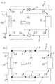
- FIG. 1 shows a thermal management system 1 for a vehicle with a combustion engine, e.g. a passenger car.
- the thermal management system 1 comprises a heat transfer fluid passed in a circuit 3 used to transfer thermal energy from the first reservoir 5 to a second reservoir 7.
- the circuit 3 is reversible, i.e. it is operable either as a heat pump or as a refrigerator. This makes it possible to transfer heat either from the first reservoir 5 to the second reservoir 7 or from the second reservoir 7 to the first reservoir 5.
- the first reservoir 5 can in particular be surrounding air.
- the second reservoir 7 can in particular be intake air for the combustion engine which is passed in an intake pipe 19.
- the circuit 3 comprises a compressor 9, a first heat transfer means 11, an expansion valve 13 and a second heat transfer means 15.
- the first heat transfer means 11 and the second heat transfer means 15 can both be operated either as evaporator or as condenser.
- the circuit 3 further comprises a first heat exchanger 17 for the transfer of thermal energy from the circuit 3 to the intake air.
- the reversibility of the circuit 3 is implemented by a number of valves 21, particularly 1-2 way valves, and by a control unit 23 for determining a heating or cooling requirement for the intake air and for controlling the valves 21 to operate the circuit 3 either as a heat pump or a refrigerator depending on the determined heating or cooling requirement.
- the heat transfer fluid is passed in the circuit 3 in the form of vapor, is compressed in the compressor 9 at constant entropy and exits the compressor 9 superheated.
- the superheated vapor then travels either through the first heat transfer means 11 or the second heat transfer means 15, depending on which of the two is used as a condenser in the present operation mode.
- the superheated vapor gives off heat and is condensed into a liquid by removing additional heat.
- the liquid heat transfer fluid then passes the expansion valve 13 where it expands and cools. From the expansion valve 13, the heat transfer fluid passes either through the first heat transfer means 11 or the second heat transfer means 15, depending on which one is operated as an evaporator. In the evaporator, the heat transfer fluid is evaporated, thereby taking up heat.
- FIG. 2 shows the thermal management system 1 in a first operation mode, where intake air in the intake pipe 19 is heated. This operation mode is advantageous in the case of a cold start.
- valves 21 are switched in a way that only the parts of the circuit 3 which are illustrated in figure 2 in solid lines are active. Heat transfer fluid is therefore only passed through part of the circuit 3 depicted in solid lines.
- the heat transfer fluid is compressed by the compressor 9 and passes as superheated vapor through the first heat transfer means 11, which is operated as a condenser.
- the heat transfer fluid gives off heat, which is transferred to the intake air by means of the first heat exchanger 17.
- the liquidised heat transfer fluid is then passed through the expansion valve 13, where its pressure is abruptly decreased, causing evaporation of at least a part of the heat transfer fluid and cooling of the heat transfer fluid.
- the heat transfer fluid then passes through the second heat transfer means 15, which is operated in this operation mode as an evaporator. There, the heat transfer fluid evaporates, taking up heat from the first reservoir 5, e.g. the surrounding air.
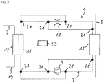
- Figure 3 shows the thermal management system 1 according to figure 1 in a second operating mode, in which it is used to cool the intake air passed in the intake pipe 19.
- This operation mode can be advantageous when the engine temperature is high.
- valves 21 are switched in a way that only the parts of the circuit 3 which are illustrated in figure 3 in solid lines are active. Heat transfer fluid is therefore only passed through part of the circuit 3 depicted in solid lines.
- heat transfer fluid is compressed by the compressor 9 and passed as superheated vapor through the second heat transfer means 15, which in this mode is operated as a condenser. There, it's gives off heat to the first reservoir 5, e.g. the surrounding air.
- the heat transfer fluid is liquidised and passed to the expansion valve 13, where its pressure abruptly decreases and the heat transfer fluid cools.
- the heat transfer fluid is passed through the first heat transfer means 11, which in this operation mode is operated as an evaporator.
- the heat transfer fluid is evaporated, thereby taking up thermal energy from the second reservoir 7 by way of the first heat exchanger 17.
- intake air passed in the intake pipe 19 is cooled.
- heat is not transferred to the intake air directly at the first heat exchanger.
- the second reservoir is a water coolant cycle of the vehicle.
- heat is transferred from the circuit 3 to a water coolant cycle and then by means of a second heat exchanger to the intake air.
Landscapes
- Engineering & Computer Science (AREA)
- Mechanical Engineering (AREA)
- Physics & Mathematics (AREA)
- Thermal Sciences (AREA)
- Chemical & Material Sciences (AREA)
- Combustion & Propulsion (AREA)
- General Engineering & Computer Science (AREA)
- Air-Conditioning For Vehicles (AREA)
Priority Applications (1)
| Application Number | Priority Date | Filing Date | Title |
|---|---|---|---|
| EP17172871.0A EP3301291A1 (de) | 2017-05-24 | 2017-05-24 | Wärmeverwaltungssystem eines fahrzeugs, fahrzeug und verfahren zum betreiben eines wärmeverwaltungssystems |
Applications Claiming Priority (1)
| Application Number | Priority Date | Filing Date | Title |
|---|---|---|---|
| EP17172871.0A EP3301291A1 (de) | 2017-05-24 | 2017-05-24 | Wärmeverwaltungssystem eines fahrzeugs, fahrzeug und verfahren zum betreiben eines wärmeverwaltungssystems |
Publications (1)
| Publication Number | Publication Date |
|---|---|
| EP3301291A1 true EP3301291A1 (de) | 2018-04-04 |
Family
ID=58778936
Family Applications (1)
| Application Number | Title | Priority Date | Filing Date |
|---|---|---|---|
| EP17172871.0A Withdrawn EP3301291A1 (de) | 2017-05-24 | 2017-05-24 | Wärmeverwaltungssystem eines fahrzeugs, fahrzeug und verfahren zum betreiben eines wärmeverwaltungssystems |
Country Status (1)
| Country | Link |
|---|---|
| EP (1) | EP3301291A1 (de) |
Citations (4)
| Publication number | Priority date | Publication date | Assignee | Title |
|---|---|---|---|---|
| US3441011A (en) * | 1967-09-05 | 1969-04-29 | Thomas M Karl | Apparatus for controlling intake air temperature |
| FR2861811A1 (fr) | 2003-11-04 | 2005-05-06 | Peugeot Citroen Automobiles Sa | Dispositif et procede de regulation thermique de gaz d'echappement recircules de vehicule automobile |
| WO2008107623A2 (fr) * | 2007-03-02 | 2008-09-12 | Renault S.A.S | Systeme et procede de gestion d'energie d'un vehicule automobile |
| EP1983170A2 (de) * | 2007-04-17 | 2008-10-22 | Behr GmbH & Co. KG | Verfahren zum Betreiben eines Kältenmittelkreislaufs mit einem Ladeluft/Kältemittel-Verdampfer |
-
2017
- 2017-05-24 EP EP17172871.0A patent/EP3301291A1/de not_active Withdrawn
Patent Citations (4)
| Publication number | Priority date | Publication date | Assignee | Title |
|---|---|---|---|---|
| US3441011A (en) * | 1967-09-05 | 1969-04-29 | Thomas M Karl | Apparatus for controlling intake air temperature |
| FR2861811A1 (fr) | 2003-11-04 | 2005-05-06 | Peugeot Citroen Automobiles Sa | Dispositif et procede de regulation thermique de gaz d'echappement recircules de vehicule automobile |
| WO2008107623A2 (fr) * | 2007-03-02 | 2008-09-12 | Renault S.A.S | Systeme et procede de gestion d'energie d'un vehicule automobile |
| EP1983170A2 (de) * | 2007-04-17 | 2008-10-22 | Behr GmbH & Co. KG | Verfahren zum Betreiben eines Kältenmittelkreislaufs mit einem Ladeluft/Kältemittel-Verdampfer |
Similar Documents
| Publication | Publication Date | Title |
|---|---|---|
| JP5596855B2 (ja) | 過給燃焼エンジンによって動力を供給される車両のための冷却器装置 | |
| EP2678548B1 (de) | System zur umwandlung von wärmeenergie in mechanische energie in einem fahrzeug | |
| US5003788A (en) | Gas engine driven heat pump system | |
| EP3878670B1 (de) | Fahrzeugtemperaturregelsystem | |
| JP4985594B2 (ja) | 車両用冷却システム | |
| EP2646671B1 (de) | Anordnung und verfahren zur umwandlung von wärmeenergie in mechanische energie | |
| US20140230761A1 (en) | Engine Energy Management System | |
| KR20140053815A (ko) | 열전 회수 및 엔진 유체의 펠티에 난방 | |
| KR20170004811A (ko) | 차량 공조 장치 및 차량 배터리의 온도 조절을 위해 상기 차량 공조 장치를 제어하기 위한 방법 | |
| US11098935B2 (en) | Method for operating an air-conditioning system of a motor vehicle | |
| CN112584669A (zh) | 冷却系统 | |
| US10662894B2 (en) | Method for controlling the temperature of a waste heat recovery system and such a waste heat recovery system | |
| JP5896817B2 (ja) | 冷却発電システム | |
| JP2019194476A (ja) | ランキンサイクルの閉ループを含む2つのサーモスタットを備えたエンジン冷却システム | |
| US20200362746A1 (en) | Control method for integrated thermal management system of vehicle | |
| US10662820B2 (en) | Method for controlling a waste heat recovery system and such a waste heat recovery system | |
| EP3301291A1 (de) | Wärmeverwaltungssystem eines fahrzeugs, fahrzeug und verfahren zum betreiben eines wärmeverwaltungssystems | |
| JP2004322933A (ja) | 車両用冷凍サイクル装置 | |
| EP2829700A2 (de) | Motorenergiemanagementsystem | |
| JP2013044239A (ja) | 車両用排熱回収装置 | |
| SE541700C2 (en) | An arrangement and a method for controlling of a WHR system | |
| WO2019130886A1 (ja) | 車両用廃熱回収装置 | |
| EP3594569A1 (de) | Wärmerückgewinnungsvorrichtung | |
| BG105182A (bg) | Система и метод за охлаждане на въздуха в превозни средства, използващи за гориво втечнен или сгъстен газ | |
| KR20090113263A (ko) | 팽창 회로 |
Legal Events
| Date | Code | Title | Description |
|---|---|---|---|
| PUAI | Public reference made under article 153(3) epc to a published international application that has entered the european phase |
Free format text: ORIGINAL CODE: 0009012 |
|
| AK | Designated contracting states |
Kind code of ref document: A1 Designated state(s): AL AT BE BG CH CY CZ DE DK EE ES FI FR GB GR HR HU IE IS IT LI LT LU LV MC MK MT NL NO PL PT RO RS SE SI SK SM TR |
|
| AX | Request for extension of the european patent |
Extension state: BA ME |
|
| STAA | Information on the status of an ep patent application or granted ep patent |
Free format text: STATUS: THE APPLICATION IS DEEMED TO BE WITHDRAWN |
|
| 18D | Application deemed to be withdrawn |
Effective date: 20181005 |