EP3301003A1 - Engine side cover structure of saddle type vehicle - Google Patents
Engine side cover structure of saddle type vehicle Download PDFInfo
- Publication number
- EP3301003A1 EP3301003A1 EP17194204.8A EP17194204A EP3301003A1 EP 3301003 A1 EP3301003 A1 EP 3301003A1 EP 17194204 A EP17194204 A EP 17194204A EP 3301003 A1 EP3301003 A1 EP 3301003A1
- Authority
- EP
- European Patent Office
- Prior art keywords
- crankcase
- side cover
- saddle type
- cover
- type vehicle
- Prior art date
- Legal status (The legal status is an assumption and is not a legal conclusion. Google has not performed a legal analysis and makes no representation as to the accuracy of the status listed.)
- Granted
Links
Images


Classifications
-
- F—MECHANICAL ENGINEERING; LIGHTING; HEATING; WEAPONS; BLASTING
- F02—COMBUSTION ENGINES; HOT-GAS OR COMBUSTION-PRODUCT ENGINE PLANTS
- F02F—CYLINDERS, PISTONS OR CASINGS, FOR COMBUSTION ENGINES; ARRANGEMENTS OF SEALINGS IN COMBUSTION ENGINES
- F02F7/00—Casings, e.g. crankcases
- F02F7/0065—Shape of casings for other machine parts and purposes, e.g. utilisation purposes, safety
- F02F7/008—Sound insulation
-
- B—PERFORMING OPERATIONS; TRANSPORTING
- B62—LAND VEHICLES FOR TRAVELLING OTHERWISE THAN ON RAILS
- B62K—CYCLES; CYCLE FRAMES; CYCLE STEERING DEVICES; RIDER-OPERATED TERMINAL CONTROLS SPECIALLY ADAPTED FOR CYCLES; CYCLE AXLE SUSPENSIONS; CYCLE SIDECARS, FORECARS, OR THE LIKE
- B62K11/00—Motorcycles, engine-assisted cycles or motor scooters with one or two wheels
- B62K11/02—Frames
- B62K11/04—Frames characterised by the engine being between front and rear wheels
-
- B—PERFORMING OPERATIONS; TRANSPORTING
- B62—LAND VEHICLES FOR TRAVELLING OTHERWISE THAN ON RAILS
- B62K—CYCLES; CYCLE FRAMES; CYCLE STEERING DEVICES; RIDER-OPERATED TERMINAL CONTROLS SPECIALLY ADAPTED FOR CYCLES; CYCLE AXLE SUSPENSIONS; CYCLE SIDECARS, FORECARS, OR THE LIKE
- B62K21/00—Steering devices
- B62K21/02—Front wheel forks or equivalent, e.g. single tine
-
- B—PERFORMING OPERATIONS; TRANSPORTING
- B62—LAND VEHICLES FOR TRAVELLING OTHERWISE THAN ON RAILS
- B62M—RIDER PROPULSION OF WHEELED VEHICLES OR SLEDGES; POWERED PROPULSION OF SLEDGES OR SINGLE-TRACK CYCLES; TRANSMISSIONS SPECIALLY ADAPTED FOR SUCH VEHICLES
- B62M7/00—Motorcycles characterised by position of motor or engine
- B62M7/02—Motorcycles characterised by position of motor or engine with engine between front and rear wheels
- B62M7/06—Motorcycles characterised by position of motor or engine with engine between front and rear wheels directly under the saddle or seat
-
- F—MECHANICAL ENGINEERING; LIGHTING; HEATING; WEAPONS; BLASTING
- F02—COMBUSTION ENGINES; HOT-GAS OR COMBUSTION-PRODUCT ENGINE PLANTS
- F02B—INTERNAL-COMBUSTION PISTON ENGINES; COMBUSTION ENGINES IN GENERAL
- F02B61/00—Adaptations of engines for driving vehicles or for driving propellers; Combinations of engines with gearing
- F02B61/02—Adaptations of engines for driving vehicles or for driving propellers; Combinations of engines with gearing for driving cycles
-
- F—MECHANICAL ENGINEERING; LIGHTING; HEATING; WEAPONS; BLASTING
- F02—COMBUSTION ENGINES; HOT-GAS OR COMBUSTION-PRODUCT ENGINE PLANTS
- F02B—INTERNAL-COMBUSTION PISTON ENGINES; COMBUSTION ENGINES IN GENERAL
- F02B77/00—Component parts, details or accessories, not otherwise provided for
- F02B77/11—Thermal or acoustic insulation
- F02B77/13—Acoustic insulation
-
- B—PERFORMING OPERATIONS; TRANSPORTING
- B60—VEHICLES IN GENERAL
- B60Y—INDEXING SCHEME RELATING TO ASPECTS CROSS-CUTTING VEHICLE TECHNOLOGY
- B60Y2200/00—Type of vehicle
- B60Y2200/10—Road Vehicles
- B60Y2200/12—Motorcycles, Trikes; Quads; Scooters
-
- B—PERFORMING OPERATIONS; TRANSPORTING
- B60—VEHICLES IN GENERAL
- B60Y—INDEXING SCHEME RELATING TO ASPECTS CROSS-CUTTING VEHICLE TECHNOLOGY
- B60Y2306/00—Other features of vehicle sub-units
- B60Y2306/09—Reducing noise
-
- F—MECHANICAL ENGINEERING; LIGHTING; HEATING; WEAPONS; BLASTING
- F02—COMBUSTION ENGINES; HOT-GAS OR COMBUSTION-PRODUCT ENGINE PLANTS
- F02F—CYLINDERS, PISTONS OR CASINGS, FOR COMBUSTION ENGINES; ARRANGEMENTS OF SEALINGS IN COMBUSTION ENGINES
- F02F7/00—Casings, e.g. crankcases
- F02F7/0043—Arrangements of mechanical drive elements
Definitions
- the present invention relates to an engine side cover structure of a saddle type vehicle.
- an engine side cover structure of a saddle type vehicle including a vehicle body frame 2 arranged between a front wheel and a rear wheel, an engine 10 including a crankcase 10a and a cylinder extending upward from the crankcase 10a, the engine 10 being supported by the vehicle body frame 2, and a side cover 48 covering a side of the crankcase 10a is conventionally known.
- the side cover 48 covers only the side part of the crankcase 10a and does not cover the back side of the crankcase 10a.
- the present invention aims to address the problem described above, and to provide an engine side cover structure of a saddle type vehicle that can also cover the back side of the crankcase.
- An engine side cover structure of a saddle type vehicle of the present invention comprises, a vehicle body frame arranged between a front wheel and a rear wheel; an engine including a crankcase, and a cylinder extending upward from the crankcase, the engine being supported by the vehicle body frame; and a side cover covering a side of the crankcase; where the side cover includes a cover main body that covers the side of the crankcase, and an extended portion that extends backward from the cover main body; and the cover main body is fixed to the crankcase, and the extended portion is fixed to the vehicle body frame.
- the side cover includes the cover main body that covers the side of the crankcase and the extended portion that extends backward from the cover main body, and thus can cover not only the side of the crankcase with the cover main body but also the back side of the crankcase with the extended portion.
- a region from the back side of the crankcase to the vehicle body frame can be covered since the cover main body is fixed to the crankcase, and the extended portion is fixed to the vehicle body frame.
- the side cover can be tightly fixed since the cover main body is fixed to the crankcase and the extended portion is fixed to the vehicle body frame.
- the vehicle body frame may include,
- the extended portion can be fixed using the pivot frame, and thus an attachment member of the extended portion does not need to be provided.
- the vehicle body frame may include,
- the electrical component can be protected even if the electrical component is arranged in the space located on the lower side of the vehicle.
- an exhaust tube coupled to the cylinder may be arranged to extend in a front and back direction at an upper side the crankcase, and a cutout may be provided at a portion adjacent to the exhaust tube at an upper part of the side cover.
- the influence on the side cover of the exhaust tube that becomes a high temperature can be suppressed and the heat resistance property of the side cover does not need to be taken into consideration, and hence lower cost of the side cover can be realized.
- the crankcase may include a bulge-out portion that bulges out outward in a vehicle width direction
- the side cover may include a first cover portion that covers the bulge-out portion and a second cover portion that covers at least one part of a periphery of the bulge-out portion
- the sound absorbing material may include at least a first sound absorbing material provided on an inner surface of the first cover portion, and a second sound absorbing material provided on an inner surface of the second cover portion
- a thickness in a vehicle width direction of the first sound absorbing material may be thinner than a thickness in the vehicle width direction of the second sound absorbing material.
- a bolt insertion hole may be formed in the extended portion, and a bolt passing through the bolt insertion hole may be tightened toward the vehicle body frame side to fix the extended portion, a diameter of the bolt insertion hole being greater than a diameter of a shaft of the bolt.
- the assembly of the side cover is facilitated as an assembly error can be tolerated by a clearance between the shaft of the bolt and the bolt insertion hole.
- the attachment bracket can be commonly used by the electrical component and the side cover thus reducing the number of parts, and at the same time, the fixing of the electrical component and the extended portion of the side cover can be carried out by effectively using a space which front side is covered with the crankcase, the back side with the pivot frame and the outer side with the extended portion.
- An engine side cover structure 1 of a saddle type vehicle shown in Figs. 1 and 2 includes a vehicle body frame 10 arranged between a front wheel WF and a rear wheel WR, an engine 20 including a crankcase 21 and a cylinder 22 extending upward from the crankcase 21, the engine 20 being supported by the vehicle frame 10, and a side cover 30 covering a side of the crankcase 21.
- the side cover 30 includes a cover main body 31 that covers the side of the crankcase 21, and an extended portion 32 that extends backward from the cover main body 31.
- the cover main body 31 is fixed to the crankcase 21, and the extended portion 32 is fixed to the vehicle body frame 10.
- the side cover 30 includes the cover main body 31 that covers the side of the crankcase 21 and the extended portion 32 that extends backward from the cover main body 31, and thus can cover not only the side of the crankcase 21 with the cover main body 31 but also the back side of the crankcase 21 with the extended portion 32.
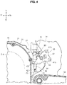
- cover main body 31 is fixed to the crankcase 21 and the extended portion 32 is fixed to the vehicle body frame 10, so that a region A1 ( Figs. 2 and 4 ) from the back side of the crankcase 21 to the vehicle body frame 10 can be covered.
- the side cover 30 can be strongly fixed since the cover main body 31 is fixed to the crankcase 21 and the extended portion 32 is fixed to the vehicle body frame 10.
- the vehicle body frame 10 includes a head pipe 11 that supports the front wheel WF by way of a front fork 12, a main tube 13 that extends backward and downward from the head pipe 11, a pivot frame 14 that extends downward from a back end of the main tube 13, a down frame 15 that extends downward from the head pipe 11, and a lower frame 16 that couples a lower end of the down frame 15 and a lower end of the pivot frame 14.
- the pivot frame 14 is arranged to extend up and down at the back side of the crankcase 21, where the extended portion 32 of the side cover 30 is fixed to the pivot frame 14.
- the extended portion 32 can be fixed using the pivot frame 14, and thus an attachment member of the extended portion 32 does not need to be provided.
- the extended portion 32 may have a structure of being fixed to an attachment member (bracket) fixed to the pivot frame 14.
- reference numeral 40 is denoted on a brake switch serving as an electrical component.
- the brake switch 40 is arranged in a space S1, which front side is covered with the crankcase 21, the back side is covered with the pivot frame 14 and an outer side is covered with the extended portion 32, at between the crankcase 21 and the pivot frame 14.
- the electrical component 40 can be protected even if the electrical component 40 is arranged in the space S1 located on the lower side of the vehicle.
- the lower side of the vehicle is not suited for the arrangement of the electrical component as gravels, and the like thrown up by the front wheel WF are often flown thereto.
- the electrical component 40 is protected with the front side covered with the crankcase 21, the back side covered with the pivot frame 14, and the outer side covered with the extended portion 32, and thus can be arranged on the lower side of the vehicle.
- an opening 33 to which the electrical component 40 faces is provided on the side surface of the extended portion 32.
- an exhaust tube 24 is coupled to the cylinder 22, which exhaust tube 24 is arranged to extend in a front and back direction at an upper side of the crankcase 21.
- a cutout 34 is formed at a portion adjacent to the exhaust tube 24 at an upper part of the side cover 30.
- the influence on the side cover 30 of the exhaust tube 24 that becomes a high temperature can be suppressed.
- the heat resistance property of the side cover 30 does not need to be taken into consideration, and lower cost of the side cover 30 can be realized.
- a sound absorbing material 50 is arranged between the side cover 30 and the crankcase 21.
- crankcase 21 includes a bulge-out portion 21b that bulges out outward in a vehicle width direction.
- the side cover 30 includes a first cover portion 31b that covers the bulge-out portion 21b, and a second cover portion 31c that covers at least one part 21c of the periphery of the bulge-out portion 21b.
- the sound absorbing material 50 includes at least a first sound absorbing material 51 provided on an inner surface of the first cover portion 31b, and a second sound absorbing material 52 provided on an inner surface of the second cover portion 31c.
- a portion (region drawn in a pointillist manner with relatively dark density) indicated with a circular chain double dashed line 51 indicates the first sound absorbing material
- a portion (region drawn in a pointillist manner with relatively light density) indicated with a U-shaped or C-shaped chain double dashed line 52 at the periphery thereof indicates the second sound absorbing material.
- a thickness t1 in the vehicle width direction of the first sound absorbing material 51 is thinner than a thickness t2 in the vehicle width direction of the second sound absorbing material 52.
- a projection amount of the side cover 30 in the vehicle width direction can be reduced as the thickness t1 in the vehicle width direction of the first sound absorbing material 51 provided on the inner surface of the first cover portion 31b that covers the bulge-out portion 21b bulging out outward in the vehicle width direction of the crank case 21 is thinner than the thickness t2 in the vehicle width direction of the second sound absorbing material 52 provided on the inner surface of the second cover portion 31c that covers at least one part of the periphery of the bulge-out portion 21b.
- the side cover 30 of the embodiment includes a third cover portion 31d that extends toward an inner side in the vehicle width direction at an upper side of the back part of the first cover portion 31b and covers the back side of the upper part of the crankcase 21, and a fourth cover portion 31e that extends toward the inner side in the vehicle width direction at the lower side of the first cover portion 31b and covers a lower part of the crank case 21.
- a third sound absorbing material 53 is provided on an inner surface of the third cover portion 31d, and a fourth sound absorbing material 54 and a fifth sound absorbing material 55 are provided on the front and back thereof on an inner surface of the fourth cover portion 31e.
- the thicknesses of the third to fifth sound absorbing materials are all thinner than the thickness t1 of the first sound absorbing material 51.
- the sound absorbing materials 50 are all made from a sheet-like urethane foam (sponge), and are respectively attached to the inner surface of the side cover.
- the thickness of the first sound absorbing material 51 is about 8 mm
- the thickness of the second sound absorbing material 52 is about 10 mm
- the thicknesses of the third to fifth sound absorbing materials are about 4 mm each.
- a plurality of (three are shown) bolt insertion holes 31h are formed in a cover main body 31 of the side cover 30, and the cover main body 31 is fixed to the crankcase 21 by tightening a bolt 31f ( Fig. 2 ) passing through the bolt insertion hole 31h to the crankcase 21.
- the cover main body 31 is fixed to the crankcase 21 by jointly tightening with a clutch cover 21d ( Fig. 2 ) that covers a right side surface of the crankcase 21 with the bolt 31f.
- the bulge-out portion 21b described above, in the embodiment is the bulge-out portion of the clutch cover 21d.
- a bolt insertion hole 32h is formed in the extended portion 32 of the cover 30, and the extended portion 32 is fixed to the vehicle body frame 10 side by tightening a bolt 32b passing through the bolt insertion hole 32h to the vehicle body frame 10 side.
- a diameter D2 of the bolt insertion hole 32h is greater than a diameter D1 of a shaft of the bolt 32b.
- the assembly of the side cover 30 is facilitated as an assembly error can be tolerated by a clearance C1 between the shaft of the bolt 32b and the bolt insertion hole 32h.
- Reference numeral 32c indicates a collar.
- the brake switch 40 serving as an electrical component described above is fixed to the pivot frame 14 by an attachment bracket 60.
- a fixing portion (female screw hole) 64 of the extended portion 32 is provided on the attachment bracket 60.
- the attachment bracket 60 can be commonly used by the electrical component 40 and the side cover 30 thus reducing the number of parts, and at the same time, the fixing of the electrical component 40 and the extended portion 32 of the side cover can be carried out by effectively using the space S1 which front side is covered with the crankcase 21, the back side with the pivot frame 14 and the outer side with the extended portion 32.
- the attachment bracket 60 includes a base portion 61 to be fixed to the pivot frame 14 with a bolt 61b, an arm portion 62 integrally extending toward the crankcase 21 from the base portion 61, and an electrical component attachment portion 63 bent toward the outer side in the vehicle width direction at a distal end of the arm portion 62, where the brake switch 40 serving as the electrical component is attached to the electrical component attachment portion 63.
- the fixing portion (female screw hole) 64 of the extended portion 32 is provided on the arm portion 62.
- a clip 65 for holding a wiring cord 41 of the electrical component 40 is provided on the attachment bracket 60 of the electrical component 40.
- H refers to the steering wheel
- T refers to the fuel tank
- S refers the seat on which a driver sits
- ST refers to a foot placing step of the driver.
- a brake pedal which is turnably attached to the pivot frame 14 with a shaft 71.
- a distal end 72c of the arm portion 72 extending forward from the shaft 71 is depressed with a foot of the driver and turned as shown with a virtual line, a rear wheel brake (not shown) is actuated by an actuation of a hydraulic cylinder 76 coupled to a back end 73, and furthermore, a rod 42 of the brake switch 40 coupled to the arm portion 72 with a link 75 is moved downward and turned ON thus turning ON a stop lamp (not shown) provided at the back part of the vehicle.
- a lower cover 80 is fixed to the vehicle body frame 10, and covers the front part to the bottom part of the crankcase 21 and a water pump WP, thus protecting the front part and the bottom part of the crankcase 21 and the water pump WP.
Landscapes
- Engineering & Computer Science (AREA)
- Mechanical Engineering (AREA)
- Chemical & Material Sciences (AREA)
- Combustion & Propulsion (AREA)
- General Engineering & Computer Science (AREA)
- Physics & Mathematics (AREA)
- Acoustics & Sound (AREA)
- Transportation (AREA)
- Cylinder Crankcases Of Internal Combustion Engines (AREA)
- Motorcycle And Bicycle Frame (AREA)
- Automatic Cycles, And Cycles In General (AREA)
Abstract
Description
- The present invention relates to an engine side cover structure of a saddle type vehicle.
- As described in Japanese Patent No.
3808184 engine 10 including a crankcase 10a and a cylinder extending upward from the crankcase 10a, theengine 10 being supported by the vehicle body frame 2, and a side cover 48 covering a side of the crankcase 10a is conventionally known. - In the conventional engine side cover structure of the saddle type vehicle described above, the side cover 48 covers only the side part of the crankcase 10a and does not cover the back side of the crankcase 10a.
- The present invention aims to address the problem described above, and to provide an engine side cover structure of a saddle type vehicle that can also cover the back side of the crankcase.
- An engine side cover structure of a saddle type vehicle of the present invention comprises,
a vehicle body frame arranged between a front wheel and a rear wheel;
an engine including a crankcase, and a cylinder extending upward from the crankcase, the engine being supported by the vehicle body frame; and
a side cover covering a side of the crankcase; where
the side cover includes a cover main body that covers the side of the crankcase, and an extended portion that extends backward from the cover main body; and
the cover main body is fixed to the crankcase, and the extended portion is fixed to the vehicle body frame. - According to the engine side cover structure of the saddle type vehicle, the side cover includes the cover main body that covers the side of the crankcase and the extended portion that extends backward from the cover main body, and thus can cover not only the side of the crankcase with the cover main body but also the back side of the crankcase with the extended portion.
- Furthermore, a region from the back side of the crankcase to the vehicle body frame can be covered since the cover main body is fixed to the crankcase, and the extended portion is fixed to the vehicle body frame.
- Moreover, the side cover can be tightly fixed since the cover main body is fixed to the crankcase and the extended portion is fixed to the vehicle body frame.
- In the engine side cover structure of the saddle type vehicle,
the vehicle body frame may include, - a head pipe that supports the front wheel by way of a front fork,
- a main tube that extends backward and downward from the head pipe, and
- a pivot frame that extends downward from a back end of the main tube; and
- According to such a configuration, the extended portion can be fixed using the pivot frame, and thus an attachment member of the extended portion does not need to be provided.
- In the engine side cover structure of the saddle type vehicle,
the vehicle body frame may include, - a head pipe that supports the front wheel by way of a front fork,
- a main tube that extends backward and downward from the head pipe, and
- a pivot frame that extends downward from a back end of the main tube; and
- According to such a configuration, the electrical component can be protected even if the electrical component is arranged in the space located on the lower side of the vehicle.
- In the engine side cover structure of the saddle type vehicle, a configuration in which an opening, to which the electrical component faces, is provided on a side surface of the extended portion can be adopted.
- According to such a configuration, maintenance of the electrical component can be carried out through the opening.
- In the engine side cover structure of the saddle type vehicle, an exhaust tube coupled to the cylinder may be arranged to extend in a front and back direction at an upper side the crankcase, and a cutout may be provided at a portion adjacent to the exhaust tube at an upper part of the side cover.
- According to such a configuration, the influence on the side cover of the exhaust tube that becomes a high temperature can be suppressed and the heat resistance property of the side cover does not need to be taken into consideration, and hence lower cost of the side cover can be realized.
- In the engine side cover structure of the saddle type vehicle, a configuration in which a sound absorbing material is arranged between the side cover and the crankcase can be adopted.
- According to such configuration, sound generated from the periphery of the crankcase is less likely to leak out to the outside.
- In the engine side cover structure of the saddle type vehicle, the crankcase may include a bulge-out portion that bulges out outward in a vehicle width direction,
the side cover may include a first cover portion that covers the bulge-out portion and a second cover portion that covers at least one part of a periphery of the bulge-out portion;
the sound absorbing material may include at least a first sound absorbing material provided on an inner surface of the first cover portion, and a second sound absorbing material provided on an inner surface of the second cover portion; and
a thickness in a vehicle width direction of the first sound absorbing material may be thinner than a thickness in the vehicle width direction of the second sound absorbing material. - According to such a configuration, sound generated from the periphery of the crankcase can be prevented from easily leaking to the outside, and a projection amount of the side cover in the vehicle width direction can be reduced as the thickness in the vehicle width direction of the first sound absorbing material provided on the inner surface of the first cover portion that covers the bulge-out portion bulging out outward in the vehicle width direction of the crank case is thinner than the thickness in the vehicle width direction of the second sound absorbing material provided on the inner surface of the second cover portion that covers at least one part of the periphery of the bulge-out portion.
- In the engine side cover structure of the saddle type vehicle, a bolt insertion hole may be formed in the extended portion, and a bolt passing through the bolt insertion hole may be tightened toward the vehicle body frame side to fix the extended portion, a diameter of the bolt insertion hole being greater than a diameter of a shaft of the bolt.
- According to such a configuration, the assembly of the side cover is facilitated as an assembly error can be tolerated by a clearance between the shaft of the bolt and the bolt insertion hole.
- In the engine side cover structure of the saddle type vehicle, a configuration in which an attachment bracket of the electrical component is fixed to the pivot frame and a fixing portion of the extended portion is provided on the attachment bracket can be adopted.
- According to such a configuration, the attachment bracket can be commonly used by the electrical component and the side cover thus reducing the number of parts, and at the same time, the fixing of the electrical component and the extended portion of the side cover can be carried out by effectively using a space which front side is covered with the crankcase, the back side with the pivot frame and the outer side with the extended portion.
- In the engine side cover structure of the saddle type vehicle, a configuration in which a clip for holding a wiring cord of the electrical component is provided on the attachment bracket of the electrical component can be adopted.
- According to such a configuration, the attachment of the electrical component and the drawing of the wiring cord are facilitated.
-
Fig. 1 is a right side view showing one example of a saddle type vehicle adopting an engine side cover structure of a saddle type vehicle according to the present invention; -
Fig. 2 is an enlarged view of a main part ofFig. 1 ; -
Fig. 3A is a schematic perspective view of the main part; -
Fig. 3B is an end view taken along a-a inFig. 3A ; -
Fig. 4 is a partially omitted left side view of the main part; -
Fig. 5 is a right side view of a side cover; -
Fig. 6A is a left side view of the side cover; and -
Fig. 6B is a cross-sectional view taken along b-b inFig. 6A . - An embodiment of an engine side cover structure of a saddle type vehicle according to the present invention will be hereinafter described by way of example and with reference to the drawings. The figures are to be viewed in the direction of a reference symbol, where in the following description, front and back, right and left, and up and down follow the direction viewed from an operator, the front side of the vehicle being indicated as Fr, rear or back side as Rr, left side as L, right side as R, upward or upper side as U, and downward or lower side as D in the figure, as necessary. In each figure, the same portion or the corresponding portion are denoted with the same reference symbol.
- An engine
side cover structure 1 of a saddle type vehicle shown inFigs. 1 and2 includes avehicle body frame 10 arranged between a front wheel WF and a rear wheel WR, anengine 20 including acrankcase 21 and acylinder 22 extending upward from thecrankcase 21, theengine 20 being supported by thevehicle frame 10, and aside cover 30 covering a side of thecrankcase 21. - As shown in
Figs. 2 to 5 , theside cover 30 includes a covermain body 31 that covers the side of thecrankcase 21, and an extendedportion 32 that extends backward from the covermain body 31. - The cover
main body 31 is fixed to thecrankcase 21, and the extendedportion 32 is fixed to thevehicle body frame 10. - According to the engine side cover structure of the saddle type vehicle, the
side cover 30 includes the covermain body 31 that covers the side of thecrankcase 21 and the extendedportion 32 that extends backward from the covermain body 31, and thus can cover not only the side of thecrankcase 21 with the covermain body 31 but also the back side of thecrankcase 21 with theextended portion 32. - Furthermore, the cover
main body 31 is fixed to thecrankcase 21 and theextended portion 32 is fixed to thevehicle body frame 10, so that a region A1 (Figs. 2 and4 ) from the back side of thecrankcase 21 to thevehicle body frame 10 can be covered. - In addition, the
side cover 30 can be strongly fixed since the covermain body 31 is fixed to thecrankcase 21 and theextended portion 32 is fixed to thevehicle body frame 10. - As shown in
Fig. 1 , thevehicle body frame 10 includes ahead pipe 11 that supports the front wheel WF by way of afront fork 12, a main tube 13 that extends backward and downward from thehead pipe 11, apivot frame 14 that extends downward from a back end of the main tube 13, adown frame 15 that extends downward from thehead pipe 11, and alower frame 16 that couples a lower end of thedown frame 15 and a lower end of thepivot frame 14. - As shown in
Fig. 2 , thepivot frame 14 is arranged to extend up and down at the back side of thecrankcase 21, where the extendedportion 32 of theside cover 30 is fixed to thepivot frame 14. - According to such configuration, the
extended portion 32 can be fixed using thepivot frame 14, and thus an attachment member of the extendedportion 32 does not need to be provided. - As will be described below, the
extended portion 32 may have a structure of being fixed to an attachment member (bracket) fixed to thepivot frame 14. - In
Figs. 2 and4 ,reference numeral 40 is denoted on a brake switch serving as an electrical component. As shown inFigs. 2 to 4 , thebrake switch 40 is arranged in a space S1, which front side is covered with thecrankcase 21, the back side is covered with thepivot frame 14 and an outer side is covered with theextended portion 32, at between thecrankcase 21 and thepivot frame 14. - According to such configuration, the
electrical component 40 can be protected even if theelectrical component 40 is arranged in the space S1 located on the lower side of the vehicle. - Normally, the lower side of the vehicle is not suited for the arrangement of the electrical component as gravels, and the like thrown up by the front wheel WF are often flown thereto.
- However, according to the embodiment, the
electrical component 40 is protected with the front side covered with thecrankcase 21, the back side covered with thepivot frame 14, and the outer side covered with theextended portion 32, and thus can be arranged on the lower side of the vehicle. - As shown in
Fig. 2 , anopening 33 to which theelectrical component 40 faces is provided on the side surface of the extendedportion 32. - According to such configuration, maintenance of the
electrical component 40 can be carried out through theopening 33. - As shown in
Figs. 1 and2 , anexhaust tube 24 is coupled to thecylinder 22, whichexhaust tube 24 is arranged to extend in a front and back direction at an upper side of thecrankcase 21. - As also shown in
Figs. 3A and 3B , acutout 34 is formed at a portion adjacent to theexhaust tube 24 at an upper part of theside cover 30. - According to such configuration, the influence on the
side cover 30 of theexhaust tube 24 that becomes a high temperature can be suppressed. Thus, the heat resistance property of theside cover 30 does not need to be taken into consideration, and lower cost of theside cover 30 can be realized. - As shown in
Figs. 3A, 3B 6A and 6B , asound absorbing material 50 is arranged between theside cover 30 and thecrankcase 21. - According to such configuration, sound generated from the periphery of the
crankcase 21 is less likely to leak out to the outside. - As shown in
Figs. 2 to 4 , thecrankcase 21 includes a bulge-outportion 21b that bulges out outward in a vehicle width direction. - The side cover 30 includes a
first cover portion 31b that covers the bulge-outportion 21b, and asecond cover portion 31c that covers at least onepart 21c of the periphery of the bulge-outportion 21b. - As shown in
Figs. 6A and 6B , thesound absorbing material 50 includes at least a firstsound absorbing material 51 provided on an inner surface of thefirst cover portion 31b, and a secondsound absorbing material 52 provided on an inner surface of thesecond cover portion 31c. - In
Fig. 6A , a portion (region drawn in a pointillist manner with relatively dark density) indicated with a circular chain double dashedline 51 indicates the first sound absorbing material, and a portion (region drawn in a pointillist manner with relatively light density) indicated with a U-shaped or C-shaped chain double dashedline 52 at the periphery thereof indicates the second sound absorbing material. - As shown in
Fig. 6B , a thickness t1 in the vehicle width direction of the firstsound absorbing material 51 is thinner than a thickness t2 in the vehicle width direction of the secondsound absorbing material 52. - According to such configuration, sound generated from the periphery of the crankcase can be prevented from easily leaking to the outside, and a projection amount of the
side cover 30 in the vehicle width direction can be reduced as the thickness t1 in the vehicle width direction of the firstsound absorbing material 51 provided on the inner surface of thefirst cover portion 31b that covers the bulge-outportion 21b bulging out outward in the vehicle width direction of thecrank case 21 is thinner than the thickness t2 in the vehicle width direction of the secondsound absorbing material 52 provided on the inner surface of thesecond cover portion 31c that covers at least one part of the periphery of the bulge-outportion 21b. - As shown in
Figs. 6A and 6B , theside cover 30 of the embodiment includes athird cover portion 31d that extends toward an inner side in the vehicle width direction at an upper side of the back part of thefirst cover portion 31b and covers the back side of the upper part of thecrankcase 21, and afourth cover portion 31e that extends toward the inner side in the vehicle width direction at the lower side of thefirst cover portion 31b and covers a lower part of thecrank case 21. - A third
sound absorbing material 53 is provided on an inner surface of thethird cover portion 31d, and a fourthsound absorbing material 54 and a fifthsound absorbing material 55 are provided on the front and back thereof on an inner surface of thefourth cover portion 31e. The thicknesses of the third to fifth sound absorbing materials are all thinner than the thickness t1 of the firstsound absorbing material 51. - The sound absorbing materials 50 (51 to 55) are all made from a sheet-like urethane foam (sponge), and are respectively attached to the inner surface of the side cover.
- The thickness of the first
sound absorbing material 51 is about 8 mm, the thickness of the secondsound absorbing material 52 is about 10 mm, and the thicknesses of the third to fifth sound absorbing materials are about 4 mm each. - As shown in
Figs. 5 ,6A and 6B , a plurality of (three are shown)bolt insertion holes 31h are formed in a covermain body 31 of theside cover 30, and the covermain body 31 is fixed to thecrankcase 21 by tightening abolt 31f (Fig. 2 ) passing through thebolt insertion hole 31h to thecrankcase 21. The covermain body 31 is fixed to thecrankcase 21 by jointly tightening with a clutch cover 21d (Fig. 2 ) that covers a right side surface of thecrankcase 21 with thebolt 31f. The bulge-outportion 21b, described above, in the embodiment is the bulge-out portion of the clutch cover 21d. - As shown in
Fig. 3B , abolt insertion hole 32h is formed in the extendedportion 32 of thecover 30, and theextended portion 32 is fixed to thevehicle body frame 10 side by tightening abolt 32b passing through thebolt insertion hole 32h to thevehicle body frame 10 side. - A diameter D2 of the
bolt insertion hole 32h is greater than a diameter D1 of a shaft of thebolt 32b. - According to such configuration, the assembly of the
side cover 30 is facilitated as an assembly error can be tolerated by a clearance C1 between the shaft of thebolt 32b and thebolt insertion hole 32h. - Reference numeral 32c indicates a collar.
- As shown in
Fig. 4 , thebrake switch 40 serving as an electrical component described above is fixed to thepivot frame 14 by anattachment bracket 60. A fixing portion (female screw hole) 64 of the extendedportion 32 is provided on theattachment bracket 60. - According to such configuration, the
attachment bracket 60 can be commonly used by theelectrical component 40 and theside cover 30 thus reducing the number of parts, and at the same time, the fixing of theelectrical component 40 and theextended portion 32 of the side cover can be carried out by effectively using the space S1 which front side is covered with thecrankcase 21, the back side with thepivot frame 14 and the outer side with theextended portion 32. - The
attachment bracket 60 includes abase portion 61 to be fixed to thepivot frame 14 with abolt 61b, anarm portion 62 integrally extending toward thecrankcase 21 from thebase portion 61, and an electricalcomponent attachment portion 63 bent toward the outer side in the vehicle width direction at a distal end of thearm portion 62, where thebrake switch 40 serving as the electrical component is attached to the electricalcomponent attachment portion 63. - The fixing portion (female screw hole) 64 of the extended
portion 32 is provided on thearm portion 62. - A
clip 65 for holding awiring cord 41 of theelectrical component 40 is provided on theattachment bracket 60 of theelectrical component 40. - According to such configuration, the attachment of the
electrical component 40 and the drawing of thewiring cord 41 are facilitated. - In
Fig. 1 , H refers to the steering wheel, T refers to the fuel tank, S refers the seat on which a driver sits, and ST refers to a foot placing step of the driver. - In
Fig. 2 , 70 is denoted on a brake pedal, which is turnably attached to thepivot frame 14 with ashaft 71. When adistal end 72c of thearm portion 72 extending forward from theshaft 71 is depressed with a foot of the driver and turned as shown with a virtual line, a rear wheel brake (not shown) is actuated by an actuation of ahydraulic cylinder 76 coupled to aback end 73, and furthermore, arod 42 of thebrake switch 40 coupled to thearm portion 72 with alink 75 is moved downward and turned ON thus turning ON a stop lamp (not shown) provided at the back part of the vehicle. - A
lower cover 80 is fixed to thevehicle body frame 10, and covers the front part to the bottom part of thecrankcase 21 and a water pump WP, thus protecting the front part and the bottom part of thecrankcase 21 and the water pump WP. - The embodiment of the present invention has been described above, but the present invention is not limited to such embodiment, and can be appropriately modified within a scope of the gist of the present invention.
-
- 1: Engine side cover structure of saddle type vehicle
- 10: Vehicle body frame
- 11: Head pipe
- 12: Front fork
- 13: Main tube
- 14: Pivot frame
- 20: Engine
- 21: Crankcase
- 21b: Bulge-out portion
- 22: Cylinder
- 24: Exhaust tube
- 30: Side cover
- 31: Cover main body
- 31b: First cover portion
- 31c: Second cover portion
- 32: Extended portion
- 32b: Bolt
- 32h: Bolt insertion hole
- 33: Opening
- 34: Cutout
- 40: Electrical component
- 41: Wiring cord
- 50 (51 to 55): Sound absorbing material
- 60: Attachment bracket
- 64: Fixing portion
- 65: Clip
- WF: Front wheel
- WR: Rear wheel
Claims (10)
- An engine side cover structure of a saddle type
vehicle comprising:a vehicle body frame (10) arranged between a front wheel (WF) and a rear wheel (WR);an engine (20) including a crankcase (21), and a cylinder (22) extending upward from the crankcase (21), the engine being supported by the vehicle body frame (10); anda side cover (30) covering a side of the crankcase (21); whereinthe side cover (30) includes a cover main body (31) that covers the side of the crankcase (21), and an extended portion (32) that extends backward from the cover main body (31); andthe cover main body (31) is fixed to the crankcase (21), and the extended portion (32) is fixed to the vehicle body frame (10). - An engine side cover structure of the saddle type vehicle according to claim 1, wherein
the vehicle body frame (10) includes,a head pipe (11) that supports the front wheel (WF) by way of a front fork (12),a main tube (13) that extends backward and downward from the head pipe (11), anda pivot frame (14) that extends downward from a back end of the main tube; andthe pivot frame (14) is arranged to extend up and down at the back side of the crankcase (21), the extended portion (32) being fixed to the pivot frame (14). - An engine side cover structure of the saddle type vehicle according to claim 1, wherein
the vehicle body frame (10) includes,a head pipe (11) that supports the front wheel (WF) by way of a front fork (12),a main tube (13) that extends backward and downward from the head pipe (11), anda pivot frame (14) that extends downward from a back end of the main tube; andan electrical component (40) is arranged in a space (S1), which front side is covered with the crankcase (21), back side is covered with the pivot frame (14), and outer side is covered with the extended portion (32) at between the crankcase (21) and the pivot frame (14). - An engine side cover structure of the saddle type vehicle according to claim 3, wherein an opening (33), to which the electrical component (40) faces, is provided on a side surface of the extended portion (32).
- An engine side cover structure of the saddle type vehicle according to any one of claims 1 to 4, wherein an exhaust tube (24) coupled to the cylinder (22) is arranged to extend in a front and back direction at an upper side of the crankcase (21), and a cutout (34) is provided at a portion adjacent to the exhaust tube (24) at an upper part of the side cover (30).
- An engine side cover structure of the saddle type vehicle according to any one of claims 1 to 5, wherein a sound absorbing material (50) is arranged between the side cover (30) and the crankcase (21).
- An engine side cover structure of the saddle type vehicle according to claim 6, wherein
the crankcase (21) includes a bulge-out portion (21b) that bulges out outward in a vehicle width direction;
the side cover (30) includes a first cover portion (31b) that covers the bulge-out portion (21b) and a second cover portion (31c) that covers at least one part (21c) of a periphery of the bulge-out portion (21b);
the sound absorbing material (50) includes at least a first sound absorbing material (51) provided on an inner surface of the first cover portion (31b), and a second sound absorbing material (52) provided on an inner surface of the second cover portion (31c); and
a thickness (tl) in a vehicle width direction of the first sound absorbing material (51) is thinner than a thickness (t2) in the vehicle width direction of the second sound absorbing material (52). - An engine side cover structure of the saddle type vehicle according to any one of claims 1 to 7, wherein
a bolt insertion hole (32h) is formed in the extended portion (32), and a bolt (32b) passing through the bolt insertion hole (32h) is tightened toward the vehicle body frame (10) side to fix the extended portion (32), a diameter (D2) of the bolt insertion hole (32h) being greater than a diameter (D1) of a shaft of the bolt (32b). - An engine side cover structure of the saddle type vehicle according to any one of claims 3 to 8, wherein an attachment bracket (60) of the electrical component (40) is fixed to the pivot frame (14) and a fixing portion (64) of the extended portion (32) is provided on the attachment bracket (60).
- An engine side cover structure of the saddle type vehicle according to claim 9, wherein a clip (65) for holding a wiring cord (41) of the electrical component (40) is provided on the attachment bracket (60) of the electrical component (40).
Applications Claiming Priority (1)
| Application Number | Priority Date | Filing Date | Title |
|---|---|---|---|
| JP2016192135A JP6492043B2 (en) | 2016-09-29 | 2016-09-29 | Engine side cover structure for saddle riding type vehicles |
Publications (2)
| Publication Number | Publication Date |
|---|---|
| EP3301003A1 true EP3301003A1 (en) | 2018-04-04 |
| EP3301003B1 EP3301003B1 (en) | 2020-02-05 |
Family
ID=60001743
Family Applications (1)
| Application Number | Title | Priority Date | Filing Date |
|---|---|---|---|
| EP17194204.8A Active EP3301003B1 (en) | 2016-09-29 | 2017-09-29 | Engine side cover structure of saddle type vehicle |
Country Status (3)
| Country | Link |
|---|---|
| US (1) | US10514000B2 (en) |
| EP (1) | EP3301003B1 (en) |
| JP (1) | JP6492043B2 (en) |
Citations (4)
| Publication number | Priority date | Publication date | Assignee | Title |
|---|---|---|---|---|
| US4396085A (en) * | 1980-09-17 | 1983-08-02 | Hondak Giken Kogyo Kabushiki Kaisha | Turbosupercharger and its associated means |
| JP3808184B2 (en) | 1997-09-03 | 2006-08-09 | 本田技研工業株式会社 | Side cover structure for motorcycle engine |
| EP1950457A2 (en) * | 2007-01-26 | 2008-07-30 | Yamaha Hatsudoki Kabushiki Kaisha | Belt-type continuously variable transmission having resin block belt and motorcycle including belt-type continuously variable transmission |
| US20140060952A1 (en) * | 2012-08-29 | 2014-03-06 | Honda Motor Co., Ltd. | Chain drive for saddle-ride type vehicle |
Family Cites Families (10)
| Publication number | Priority date | Publication date | Assignee | Title |
|---|---|---|---|---|
| JPS604854Y2 (en) * | 1982-05-24 | 1985-02-13 | 本田技研工業株式会社 | Motorcycle power unit side cover device |
| US4913256A (en) * | 1986-05-30 | 1990-04-03 | Honda Giken Kogyo Kabushiki Kaisha | Motorcycle |
| JP3916376B2 (en) * | 2000-06-15 | 2007-05-16 | 本田技研工業株式会社 | Breather structure of internal combustion engine for vehicle |
| US6941920B1 (en) * | 2004-04-02 | 2005-09-13 | Kenneth R. Thurm | Motorcycle engine and transmission interbracing member |
| JP4911973B2 (en) * | 2005-12-28 | 2012-04-04 | 本田技研工業株式会社 | Arrangement structure of brake control device for motorcycle |
| JP6196083B2 (en) * | 2013-07-10 | 2017-09-13 | 本田技研工業株式会社 | Motorcycle |
| EP2949567B1 (en) * | 2014-05-30 | 2019-12-04 | Yamaha Motor Co., Ltd. | Straddle type vehicle with single cylinder engine |
| JP6280483B2 (en) * | 2014-09-30 | 2018-02-14 | 本田技研工業株式会社 | Cooling structure for saddle-ride type vehicles |
| JP6282991B2 (en) * | 2015-03-13 | 2018-02-21 | 本田技研工業株式会社 | Body cover structure for saddle-ride type vehicles |
| JP6235511B2 (en) * | 2015-03-19 | 2017-11-22 | 本田技研工業株式会社 | Saddle riding |
-
2016
- 2016-09-29 JP JP2016192135A patent/JP6492043B2/en active Active
-
2017
- 2017-09-25 US US15/714,407 patent/US10514000B2/en active Active
- 2017-09-29 EP EP17194204.8A patent/EP3301003B1/en active Active
Patent Citations (4)
| Publication number | Priority date | Publication date | Assignee | Title |
|---|---|---|---|---|
| US4396085A (en) * | 1980-09-17 | 1983-08-02 | Hondak Giken Kogyo Kabushiki Kaisha | Turbosupercharger and its associated means |
| JP3808184B2 (en) | 1997-09-03 | 2006-08-09 | 本田技研工業株式会社 | Side cover structure for motorcycle engine |
| EP1950457A2 (en) * | 2007-01-26 | 2008-07-30 | Yamaha Hatsudoki Kabushiki Kaisha | Belt-type continuously variable transmission having resin block belt and motorcycle including belt-type continuously variable transmission |
| US20140060952A1 (en) * | 2012-08-29 | 2014-03-06 | Honda Motor Co., Ltd. | Chain drive for saddle-ride type vehicle |
Also Published As
| Publication number | Publication date |
|---|---|
| JP2018052368A (en) | 2018-04-05 |
| US20180087472A1 (en) | 2018-03-29 |
| JP6492043B2 (en) | 2019-03-27 |
| EP3301003B1 (en) | 2020-02-05 |
| US10514000B2 (en) | 2019-12-24 |
Similar Documents
| Publication | Publication Date | Title |
|---|---|---|
| US8256557B2 (en) | Canister mounting structure for a saddle-type vehicle, and vehicle incorporating same | |
| US8167467B2 (en) | Rear lamp assembly for a saddle-type vehicle, and vehicle incorporating same | |
| US8783399B2 (en) | Saddle-riding type vehicle including multi-part shroud | |
| CN105246774B (en) | Exhaust pipe side cover of automatic motorcycle | |
| JP6130119B2 (en) | Motorcycle | |
| TWI359761B (en) | Straddle-type vehicle | |
| JP2009162093A (en) | Silencer protector and saddle riding type vehicle | |
| EP3301003B1 (en) | Engine side cover structure of saddle type vehicle | |
| JP2006069501A (en) | Saddle type vehicle fuel tank mounting structure | |
| EP2075188B1 (en) | Straddle-type vehicle | |
| JP2019119438A (en) | Tank cover structure of saddle-riding type vehicle | |
| EP2159141B1 (en) | A cover assembly for a motorcycle and a motorcycle equipped with such a cover assembly | |
| US7513559B2 (en) | Vehicle | |
| JP2005104313A (en) | Side cover structure for motorcycles | |
| JP4855201B2 (en) | Motorcycle | |
| US7686121B2 (en) | All terrain vehicle | |
| JP2019172190A (en) | Side cover structure of saddle-riding type vehicle | |
| JP4720482B2 (en) | Motorcycle frame cover | |
| EP2711277B1 (en) | Frame structure for saddle-riding type automotive vehicle | |
| JP5702667B2 (en) | Step structure of saddle riding type vehicle | |
| JP7212800B2 (en) | straddle-type vehicle | |
| JP2007091195A (en) | Motorcycle wiring / piping support equipment | |
| JP5981476B2 (en) | Brake pedal support structure for saddle-ride type vehicles | |
| EP2017170B1 (en) | Straddle-type vehicle | |
| JP6259088B2 (en) | Saddle riding |
Legal Events
| Date | Code | Title | Description |
|---|---|---|---|
| PUAI | Public reference made under article 153(3) epc to a published international application that has entered the european phase |
Free format text: ORIGINAL CODE: 0009012 |
|
| STAA | Information on the status of an ep patent application or granted ep patent |
Free format text: STATUS: REQUEST FOR EXAMINATION WAS MADE |
|
| 17P | Request for examination filed |
Effective date: 20170929 |
|
| AK | Designated contracting states |
Kind code of ref document: A1 Designated state(s): AL AT BE BG CH CY CZ DE DK EE ES FI FR GB GR HR HU IE IS IT LI LT LU LV MC MK MT NL NO PL PT RO RS SE SI SK SM TR |
|
| AX | Request for extension of the european patent |
Extension state: BA ME |
|
| STAA | Information on the status of an ep patent application or granted ep patent |
Free format text: STATUS: EXAMINATION IS IN PROGRESS |
|
| 17Q | First examination report despatched |
Effective date: 20190124 |
|
| GRAP | Despatch of communication of intention to grant a patent |
Free format text: ORIGINAL CODE: EPIDOSNIGR1 |
|
| STAA | Information on the status of an ep patent application or granted ep patent |
Free format text: STATUS: GRANT OF PATENT IS INTENDED |
|
| INTG | Intention to grant announced |
Effective date: 20190808 |
|
| GRAS | Grant fee paid |
Free format text: ORIGINAL CODE: EPIDOSNIGR3 |
|
| GRAA | (expected) grant |
Free format text: ORIGINAL CODE: 0009210 |
|
| STAA | Information on the status of an ep patent application or granted ep patent |
Free format text: STATUS: THE PATENT HAS BEEN GRANTED |
|
| AK | Designated contracting states |
Kind code of ref document: B1 Designated state(s): AL AT BE BG CH CY CZ DE DK EE ES FI FR GB GR HR HU IE IS IT LI LT LU LV MC MK MT NL NO PL PT RO RS SE SI SK SM TR |
|
| REG | Reference to a national code |
Ref country code: GB Ref legal event code: FG4D |
|
| REG | Reference to a national code |
Ref country code: AT Ref legal event code: REF Ref document number: 1229707 Country of ref document: AT Kind code of ref document: T Effective date: 20200215 |
|
| REG | Reference to a national code |
Ref country code: DE Ref legal event code: R096 Ref document number: 602017011340 Country of ref document: DE |
|
| REG | Reference to a national code |
Ref country code: IE Ref legal event code: FG4D |
|
| REG | Reference to a national code |
Ref country code: CH Ref legal event code: EP |
|
| REG | Reference to a national code |
Ref country code: NL Ref legal event code: MP Effective date: 20200205 |
|
| PG25 | Lapsed in a contracting state [announced via postgrant information from national office to epo] |
Ref country code: RS Free format text: LAPSE BECAUSE OF FAILURE TO SUBMIT A TRANSLATION OF THE DESCRIPTION OR TO PAY THE FEE WITHIN THE PRESCRIBED TIME-LIMIT Effective date: 20200205 Ref country code: NO Free format text: LAPSE BECAUSE OF FAILURE TO SUBMIT A TRANSLATION OF THE DESCRIPTION OR TO PAY THE FEE WITHIN THE PRESCRIBED TIME-LIMIT Effective date: 20200505 Ref country code: PT Free format text: LAPSE BECAUSE OF FAILURE TO SUBMIT A TRANSLATION OF THE DESCRIPTION OR TO PAY THE FEE WITHIN THE PRESCRIBED TIME-LIMIT Effective date: 20200628 Ref country code: FI Free format text: LAPSE BECAUSE OF FAILURE TO SUBMIT A TRANSLATION OF THE DESCRIPTION OR TO PAY THE FEE WITHIN THE PRESCRIBED TIME-LIMIT Effective date: 20200205 |
|
| REG | Reference to a national code |
Ref country code: LT Ref legal event code: MG4D |
|
| PG25 | Lapsed in a contracting state [announced via postgrant information from national office to epo] |
Ref country code: LV Free format text: LAPSE BECAUSE OF FAILURE TO SUBMIT A TRANSLATION OF THE DESCRIPTION OR TO PAY THE FEE WITHIN THE PRESCRIBED TIME-LIMIT Effective date: 20200205 Ref country code: SE Free format text: LAPSE BECAUSE OF FAILURE TO SUBMIT A TRANSLATION OF THE DESCRIPTION OR TO PAY THE FEE WITHIN THE PRESCRIBED TIME-LIMIT Effective date: 20200205 Ref country code: HR Free format text: LAPSE BECAUSE OF FAILURE TO SUBMIT A TRANSLATION OF THE DESCRIPTION OR TO PAY THE FEE WITHIN THE PRESCRIBED TIME-LIMIT Effective date: 20200205 Ref country code: BG Free format text: LAPSE BECAUSE OF FAILURE TO SUBMIT A TRANSLATION OF THE DESCRIPTION OR TO PAY THE FEE WITHIN THE PRESCRIBED TIME-LIMIT Effective date: 20200505 Ref country code: GR Free format text: LAPSE BECAUSE OF FAILURE TO SUBMIT A TRANSLATION OF THE DESCRIPTION OR TO PAY THE FEE WITHIN THE PRESCRIBED TIME-LIMIT Effective date: 20200506 Ref country code: IS Free format text: LAPSE BECAUSE OF FAILURE TO SUBMIT A TRANSLATION OF THE DESCRIPTION OR TO PAY THE FEE WITHIN THE PRESCRIBED TIME-LIMIT Effective date: 20200605 |
|
| PG25 | Lapsed in a contracting state [announced via postgrant information from national office to epo] |
Ref country code: NL Free format text: LAPSE BECAUSE OF FAILURE TO SUBMIT A TRANSLATION OF THE DESCRIPTION OR TO PAY THE FEE WITHIN THE PRESCRIBED TIME-LIMIT Effective date: 20200205 |
|
| PG25 | Lapsed in a contracting state [announced via postgrant information from national office to epo] |
Ref country code: SK Free format text: LAPSE BECAUSE OF FAILURE TO SUBMIT A TRANSLATION OF THE DESCRIPTION OR TO PAY THE FEE WITHIN THE PRESCRIBED TIME-LIMIT Effective date: 20200205 Ref country code: EE Free format text: LAPSE BECAUSE OF FAILURE TO SUBMIT A TRANSLATION OF THE DESCRIPTION OR TO PAY THE FEE WITHIN THE PRESCRIBED TIME-LIMIT Effective date: 20200205 Ref country code: SM Free format text: LAPSE BECAUSE OF FAILURE TO SUBMIT A TRANSLATION OF THE DESCRIPTION OR TO PAY THE FEE WITHIN THE PRESCRIBED TIME-LIMIT Effective date: 20200205 Ref country code: LT Free format text: LAPSE BECAUSE OF FAILURE TO SUBMIT A TRANSLATION OF THE DESCRIPTION OR TO PAY THE FEE WITHIN THE PRESCRIBED TIME-LIMIT Effective date: 20200205 Ref country code: RO Free format text: LAPSE BECAUSE OF FAILURE TO SUBMIT A TRANSLATION OF THE DESCRIPTION OR TO PAY THE FEE WITHIN THE PRESCRIBED TIME-LIMIT Effective date: 20200205 Ref country code: CZ Free format text: LAPSE BECAUSE OF FAILURE TO SUBMIT A TRANSLATION OF THE DESCRIPTION OR TO PAY THE FEE WITHIN THE PRESCRIBED TIME-LIMIT Effective date: 20200205 Ref country code: ES Free format text: LAPSE BECAUSE OF FAILURE TO SUBMIT A TRANSLATION OF THE DESCRIPTION OR TO PAY THE FEE WITHIN THE PRESCRIBED TIME-LIMIT Effective date: 20200205 Ref country code: DK Free format text: LAPSE BECAUSE OF FAILURE TO SUBMIT A TRANSLATION OF THE DESCRIPTION OR TO PAY THE FEE WITHIN THE PRESCRIBED TIME-LIMIT Effective date: 20200205 |
|
| PGFP | Annual fee paid to national office [announced via postgrant information from national office to epo] |
Ref country code: DE Payment date: 20200922 Year of fee payment: 4 |
|
| REG | Reference to a national code |
Ref country code: DE Ref legal event code: R097 Ref document number: 602017011340 Country of ref document: DE |
|
| REG | Reference to a national code |
Ref country code: AT Ref legal event code: MK05 Ref document number: 1229707 Country of ref document: AT Kind code of ref document: T Effective date: 20200205 |
|
| PLBE | No opposition filed within time limit |
Free format text: ORIGINAL CODE: 0009261 |
|
| STAA | Information on the status of an ep patent application or granted ep patent |
Free format text: STATUS: NO OPPOSITION FILED WITHIN TIME LIMIT |
|
| 26N | No opposition filed |
Effective date: 20201106 |
|
| PG25 | Lapsed in a contracting state [announced via postgrant information from national office to epo] |
Ref country code: AT Free format text: LAPSE BECAUSE OF FAILURE TO SUBMIT A TRANSLATION OF THE DESCRIPTION OR TO PAY THE FEE WITHIN THE PRESCRIBED TIME-LIMIT Effective date: 20200205 Ref country code: IT Free format text: LAPSE BECAUSE OF FAILURE TO SUBMIT A TRANSLATION OF THE DESCRIPTION OR TO PAY THE FEE WITHIN THE PRESCRIBED TIME-LIMIT Effective date: 20200205 |
|
| PG25 | Lapsed in a contracting state [announced via postgrant information from national office to epo] |
Ref country code: SI Free format text: LAPSE BECAUSE OF FAILURE TO SUBMIT A TRANSLATION OF THE DESCRIPTION OR TO PAY THE FEE WITHIN THE PRESCRIBED TIME-LIMIT Effective date: 20200205 Ref country code: PL Free format text: LAPSE BECAUSE OF FAILURE TO SUBMIT A TRANSLATION OF THE DESCRIPTION OR TO PAY THE FEE WITHIN THE PRESCRIBED TIME-LIMIT Effective date: 20200205 |
|
| REG | Reference to a national code |
Ref country code: CH Ref legal event code: PL |
|
| REG | Reference to a national code |
Ref country code: BE Ref legal event code: MM Effective date: 20200930 |
|
| PG25 | Lapsed in a contracting state [announced via postgrant information from national office to epo] |
Ref country code: LU Free format text: LAPSE BECAUSE OF NON-PAYMENT OF DUE FEES Effective date: 20200929 |
|
| PG25 | Lapsed in a contracting state [announced via postgrant information from national office to epo] |
Ref country code: FR Free format text: LAPSE BECAUSE OF NON-PAYMENT OF DUE FEES Effective date: 20200930 |
|
| PG25 | Lapsed in a contracting state [announced via postgrant information from national office to epo] |
Ref country code: LI Free format text: LAPSE BECAUSE OF NON-PAYMENT OF DUE FEES Effective date: 20200930 Ref country code: IE Free format text: LAPSE BECAUSE OF NON-PAYMENT OF DUE FEES Effective date: 20200929 Ref country code: BE Free format text: LAPSE BECAUSE OF NON-PAYMENT OF DUE FEES Effective date: 20200930 Ref country code: CH Free format text: LAPSE BECAUSE OF NON-PAYMENT OF DUE FEES Effective date: 20200930 |
|
| REG | Reference to a national code |
Ref country code: DE Ref legal event code: R119 Ref document number: 602017011340 Country of ref document: DE |
|
| GBPC | Gb: european patent ceased through non-payment of renewal fee |
Effective date: 20210929 |
|
| PG25 | Lapsed in a contracting state [announced via postgrant information from national office to epo] |
Ref country code: TR Free format text: LAPSE BECAUSE OF FAILURE TO SUBMIT A TRANSLATION OF THE DESCRIPTION OR TO PAY THE FEE WITHIN THE PRESCRIBED TIME-LIMIT Effective date: 20200205 Ref country code: MT Free format text: LAPSE BECAUSE OF FAILURE TO SUBMIT A TRANSLATION OF THE DESCRIPTION OR TO PAY THE FEE WITHIN THE PRESCRIBED TIME-LIMIT Effective date: 20200205 Ref country code: CY Free format text: LAPSE BECAUSE OF FAILURE TO SUBMIT A TRANSLATION OF THE DESCRIPTION OR TO PAY THE FEE WITHIN THE PRESCRIBED TIME-LIMIT Effective date: 20200205 |
|
| PG25 | Lapsed in a contracting state [announced via postgrant information from national office to epo] |
Ref country code: MK Free format text: LAPSE BECAUSE OF FAILURE TO SUBMIT A TRANSLATION OF THE DESCRIPTION OR TO PAY THE FEE WITHIN THE PRESCRIBED TIME-LIMIT Effective date: 20200205 Ref country code: MC Free format text: LAPSE BECAUSE OF FAILURE TO SUBMIT A TRANSLATION OF THE DESCRIPTION OR TO PAY THE FEE WITHIN THE PRESCRIBED TIME-LIMIT Effective date: 20200205 Ref country code: AL Free format text: LAPSE BECAUSE OF FAILURE TO SUBMIT A TRANSLATION OF THE DESCRIPTION OR TO PAY THE FEE WITHIN THE PRESCRIBED TIME-LIMIT Effective date: 20200205 |
|
| PG25 | Lapsed in a contracting state [announced via postgrant information from national office to epo] |
Ref country code: GB Free format text: LAPSE BECAUSE OF NON-PAYMENT OF DUE FEES Effective date: 20210929 Ref country code: DE Free format text: LAPSE BECAUSE OF NON-PAYMENT OF DUE FEES Effective date: 20220401 |