EP3300909A1 - Printing apparatus and printing method - Google Patents
Printing apparatus and printing method Download PDFInfo
- Publication number
- EP3300909A1 EP3300909A1 EP17192993.8A EP17192993A EP3300909A1 EP 3300909 A1 EP3300909 A1 EP 3300909A1 EP 17192993 A EP17192993 A EP 17192993A EP 3300909 A1 EP3300909 A1 EP 3300909A1
- Authority
- EP
- European Patent Office
- Prior art keywords
- unit
- suction
- reading
- printing
- transport
- Prior art date
- Legal status (The legal status is an assumption and is not a legal conclusion. Google has not performed a legal analysis and makes no representation as to the accuracy of the status listed.)
- Withdrawn
Links
Images










Classifications
-
- B—PERFORMING OPERATIONS; TRANSPORTING
- B41—PRINTING; LINING MACHINES; TYPEWRITERS; STAMPS
- B41J—TYPEWRITERS; SELECTIVE PRINTING MECHANISMS, i.e. MECHANISMS PRINTING OTHERWISE THAN FROM A FORME; CORRECTION OF TYPOGRAPHICAL ERRORS
- B41J11/00—Devices or arrangements of selective printing mechanisms, e.g. ink-jet printers or thermal printers, for supporting or handling copy material in sheet or web form
- B41J11/0085—Using suction for maintaining printing material flat
-
- B—PERFORMING OPERATIONS; TRANSPORTING
- B41—PRINTING; LINING MACHINES; TYPEWRITERS; STAMPS
- B41J—TYPEWRITERS; SELECTIVE PRINTING MECHANISMS, i.e. MECHANISMS PRINTING OTHERWISE THAN FROM A FORME; CORRECTION OF TYPOGRAPHICAL ERRORS
- B41J13/00—Devices or arrangements of selective printing mechanisms, e.g. ink-jet printers or thermal printers, specially adapted for supporting or handling copy material in short lengths, e.g. sheets
- B41J13/10—Sheet holders, retainers, movable guides, or stationary guides
- B41J13/22—Clamps or grippers
- B41J13/223—Clamps or grippers on rotatable drums
- B41J13/226—Clamps or grippers on rotatable drums using suction
-
- B—PERFORMING OPERATIONS; TRANSPORTING
- B41—PRINTING; LINING MACHINES; TYPEWRITERS; STAMPS
- B41J—TYPEWRITERS; SELECTIVE PRINTING MECHANISMS, i.e. MECHANISMS PRINTING OTHERWISE THAN FROM A FORME; CORRECTION OF TYPOGRAPHICAL ERRORS
- B41J29/00—Details of, or accessories for, typewriters or selective printing mechanisms not otherwise provided for
- B41J29/38—Drives, motors, controls or automatic cut-off devices for the entire printing mechanism
- B41J29/393—Devices for controlling or analysing the entire machine ; Controlling or analysing mechanical parameters involving printing of test patterns
Definitions
- the present invention relates to a printing apparatus and a printing method, and particularly, to a printing apparatus and a printing method that suctions and transports a recording medium.
- JP2015-123590A discloses a device that changes suction pressure for a print medium in a case of printing and in a case of reading in order to suction the print medium according to a suction force allowing movement of the print medium in a scanning region of a reading sensor.
- JP2011-195295A discloses a device that has a plurality of suction regions capable of an electrostatic suction force provided in a suction force generation unit performing electrostatic suction and which controls an electrostatic suction force according to the state of a back surface of a print medium.
- JP2015-123590A and JP2011-195295A are equivalent to a recording medium in the present specification. By suctioning and transporting the recording medium in this way, the transport performance during printing can be secured.
- reading an image printed on a recording medium by a printhead obtaining the amount of correction of a printing property of the printhead from the read image data, and correcting the printhead with the obtained amount of correction are performed.
- the shapes appear on the front surface of a suctioned recording medium. Accordingly, there is a case where the read image data does not become suitable data and the amount of correction of the printing property cannot be appropriately obtained.
- the invention has been made in view of such circumstances, and an object thereof is to provide a printing apparatus and a printing method that allow transport performance, and reading and correction performance to be compatible with each other.
- a printing apparatus comprising a supporting part that brings an opposite surface of a recording surface of a recording medium into contact with a supporting surface having shapes of at least one of a plurality of concave shapes or a plurality of convex shapes to support the recording surface; a suction unit that suctions the recording medium supported by the supporting part with a first suction force per unit area on the supporting surface; a transport unit that transports the recording medium suctioned on the supporting surface along a transport path; a printing unit that is disposed to face the transport path, prints an image based on input data on the recording surface at a printing position of the transport path; a reading unit that is disposed to face the transport path on a downstream side of the transport path with respect to the printing unit, and reads the recording surface at a reading position of the transport path; a correction unit that corrects at least one of the printing unit or the reading unit on the basis of a reading result of the reading unit; and a controller that controls a
- the recording medium is suctioned with the first suction force per unit area, and the recording medium is suctioned on the suction unit with the second suction force per unit area smaller than the first suction force per unit area or the suction of the suction unit is stopped, at least in a case where the reading unit reads the image using the reading result in the correction unit.
- the recording medium can be stably transported, and the reading result used in the correction unit is not influenced by the concave shapes and the convex shapes of the supporting surface.
- transport performance, and reading, and correction performance can be made compatible with each other.
- the printing unit includes an ink jet head that applies ink to print an image on the recording surface of the recording medium, and a defect detection unit that detects a defect of the image on the basis of the reading result of the reading unit, and the controller makes the suction force per unit area of the suction unit at the reading position smaller in a region where the amount of ink to be applied to the recording surface is smaller, in a case where the reading unit reads the image using the reading result in the defect detection unit. Accordingly, the image defect can be appropriately detected without the reading result being influenced by the concave shapes and the convex shapes of the supporting surface.
- the controller makes the suction force at the reading position smaller by advancing a timing of when the suction force per unit area of the suction unit is made smaller, as the amount of ink of the printed image becomes smaller. Accordingly, the image defect can be appropriately detected without the reading result being influenced by the concave shapes and the convex shapes of the supporting surface.
- the supporting surface has a plurality of regions split in a direction orthogonal to a transport direction of the recording medium, and the controller controls the suction force per unit area of the suction unit in each of the plurality of regions. Accordingly, the suction force can be appropriately controlled.
- the supporting surface has a plurality of regions split in a transport direction of the recording medium and a direction orthogonal to the transport direction of the recording medium, and the controller controls the suction force per unit area of the suction unit in each of the plurality of regions. Accordingly, the suction force can be appropriately controlled.
- the printing apparatus further comprises a display unit that displays the reading result of the reading unit in an enhanced manner; and an adjustment unit that allows a user to adjust at least one of the suction force per unit area of the suction unit at the reading position or a timing of when the suction force is made small. Accordingly, the influence caused by the concave shapes and the convex shapes of the supporting surface in the reading result can be appropriately eliminated.
- the suction unit includes a vacuuming unit that vacuums gas from a suction hole formed in the supporting surface to suction the recording medium. Even in the suction unit including such a suction unit, the influence caused by the concave shapes and the convex shapes of the supporting surface on the reading result can be appropriately eliminated.
- the transport unit includes a transport drum that rotates the recording medium suctioned on an outer peripheral surface to be transported along the transport path.
- the supporting surface includes a jacket having shapes of at least one of the plurality of concave shapes or the plurality of convex shapes. Even in such a transport unit, the influence caused by the concave shapes and the convex shapes of the supporting surface of the reading unit can be appropriately eliminated.
- the reading unit includes a plurality of photoelectric conversion elements, and the correction unit that corrects sensitivity of the plurality of photoelectric conversion elements on the basis of the reading result of the reading unit. Accordingly, since the influence caused by the concave shapes and the convex shapes of the supporting surface on the reading result can be appropriately eliminated, the sensitivity of the plurality of photoelectric conversion elements can be appropriately corrected.
- the printing unit prints an image by a plurality of recording elements, and the correction unit corrects input data corresponding to the recording elements on the basis of the reading result of the reading unit.
- the printing unit may print an image by a plurality of recording elements, and the correction unit may correct drive conditions of the plurality of recording elements on the basis of the reading result of the reading unit. Accordingly, since the influence caused by the concave shapes and the convex shapes of the supporting surface on the reading result can be appropriately eliminated, the input data corresponding to the plurality of recording elements and/or the drive conditions of the plurality of recording elements can be appropriately corrected.
- one aspect of a printing method is a printing method comprising a suction step of bringing an opposite surface of a recording surface of a recording medium into contact with a supporting surface having shapes of at least one of a plurality of concave shapes or a plurality of convex shapes to support the recording surface and suctioning the supported recording medium with a suction force per a first unit area on the supporting surface; a transport step of transporting the recording medium suctioned on the supporting surface along a transport path; a printing step of printing an image based on input data on the recording surface at a printing position of the transport path by a printing unit disposed to face the transport path;a reading step of reading the recording surface at a reading position of the transport path by a reading unit disposed to face the transport path on a downstream side of the transport path with respect to the printing unit; a correction step of correcting at least one of the printing unit or the reading unit on the basis of a reading result of the reading step; and a control step of controlling a suction step of bringing an opposite
- the recording medium is suctioned with the first suction force per unit area, and the recording medium is suctioned on the suction unit with the second suction force per unit area smaller than the first suction force per unit area or the suction of the suction unit is stopped, at least in a case where the reading unit reads the image using the reading result in the correction unit.
- the recording medium can be stably transported, and the reading result used in the correction unit is not influenced by the concave shapes and the convex shapes of the supporting surface.
- transport performance, and reading, and correction performance can be made compatible with each other.
- transport performance, and reading, and correction performance can be made compatible with each other.
- Fig. 1 is a schematic view illustrating an overall configuration of an ink jet printing apparatus 10 related to the present embodiment.
- the ink jet printing apparatus 10 is a single path type line printer that prints an image on a recording surface of paper 1 (an example of a recording medium), and includes a paper feed unit 20, a transport unit 30, a printing unit 40, a reading unit 60, a paper ejection unit 70, and the like.
- the transport unit 30 includes a transport drum 100.
- the transport drum 100 has a transport surface 102 (an example of a supporting surface) and a rotary shaft 104 that holds the paper 1. Additionally, two grippers 106 for gripping a leading end of the paper 1 are provided at positions that face each other with the rotary shaft 104 of the transport surface 102 interposed therebetween.
- a large number of suction holes 110 (refer to Fig. 4 ) is formed in a fixed pattern on the transport surface of the transport drum 100.
- the paper 1 introduced from the paper feed unit 20 has its leading end gripped by the grippers 106 and is wound around the transport surface 102 of the transport drum 100 that is rotating.
- suction holes 110 a surface opposite to the recording surface is suctioned on and held by the transport surface 102 of the transport drum 100.
- the transport drum 100 holds the paper 1 on the transport surface 102 and rotates in the counterclockwise direction in Fig. 1 around the rotary shaft 104, thereby transporting the paper 1 along a transport path.
- the printing unit 40 includes four ink jet heads 42M, 42K, 42C, and 42Y, and the ink jet heads 42M, 42K, 42C, and 42Y are respectively disposed sequentially from an upstream side at regular intervals along the transport path of the paper 1 on the transport drum 100. Additionally, the ink jet heads 42M, 42K, 42C, and 42Y respectively include nozzle surfaces 44M, 44K, 44C, and 44Y that face the transport drum 100, and a plurality of nozzles 48 (refer to Fig.
- M ink magenta ink
- K ink black ink
- C ink cyan ink
- Y ink yellow ink
- the respective ink jet heads 42M, 42K, 42C, and 42Y are held such that the respective nozzle surfaces 44M, 44K, 44C, and 44Y become parallel to tangential directions of positions that face the respective nozzle surfaces 44M, 44K, 44C, and 44Y of the transport surface of the transport drum 100.
- the ink jet heads 42M, 42K, 42C, and 42Y discharge ink from the respective nozzles 48 on the basis of input image data (an example of input data) and prints an image on the recording surface of the paper 1 transported on the transport drum 100.
- the reading unit 60 is disposed on a downstream side of the printing unit 40 on the transport path of the transport drum 100.
- the reading unit 60 includes an in-line sensor 62.
- a plurality of photoelectric conversion elements 62S (refer to Fig. 9 ) capable of reading a length corresponding to the full width of the paper 1 are disposed in the in-line sensor 62.
- the in-line sensor 62 irradiates the recording surface of the paper 1 with light in a case where the paper 1 passes through the reading position P R , reads an image recorded on the recording surface of the paper 1 from reflected light, and converts the image into read image data.
- the distance in a transport direction between the printing unit 40 and the reading unit 60 is shorter than the length of the paper 1 in its transport direction. Hence, the paper 1 during transport may straddle both of the printing position Pw and the reading position P R .
- Fig. 2 is a view of the ink jet head 42M as seen from the nozzle surface 44M side
- Fig. 3 is a partially enlarged view of Fig. 2 .
- the ink jet head 42M has an elongated structure in which seventeen head modules 46-1 to 46-17 are connected together in an X direction, and a plurality of nozzles 48 are disposed in two dimensions over a length corresponding to the full width of the paper 1 on the nozzle surface 44M.
- Each of the plurality of nozzles 48 includes a piezoelectric actuator 48S (refer to an example of a recording element, and Fig. 9 ) as a droplet discharge element, and ink is discharged from each nozzle 48 by driving the piezoelectric actuator 48S.
- a thermal jet method or the like may be used as a method of discharging ink from the nozzle 48.
- the respective head modules 46-1 to 46-17 are configured in a replaceable manner, and are supported by a head module supporting member 50 from both sides of the ink jet head 42M in its lateral direction. Additionally, both end parts of the ink jet head 42M in its longitudinal direction are supported by a head supporting member 52.
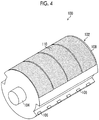
- Fig. 4 is a perspective view illustrating an overall structure of the transport drum 100
- Fig. 5 is an exploded perspective view illustrating an internal structure of the transport drum 100.
- the transport drum 100 includes a ceramic jacket 108 in which a large number of suction holes 110 are formed on a front surface constituting the transport surface 102, and a main drum body 114 including a drum suction groove 112, and is configured such that the ceramic jacket 108 is mounted on the main drum body 114.
- a drum suction hole 116 that communicates with a vacuum flow passage (not illustrated) provided inside the main drum body 114 is provided at an end part of the drum suction groove 112 provided on a peripheral surface of the main drum body 114.
- Fig. 6 is a view illustrating a front surface (the surface constituting the transport surface 102) of the ceramic jacket 108.
- the large number of suction holes 110 an example of concave shapes
- a large number of projections 118 an example of convex shapes
- Fig. 7 is a 7-7 sectional view of Fig. 6 .
- the ceramic jacket 108 is constituted of a suction hole layer 108A on the front surface side which constitutes the transport surface 102 of the transport drum 100, and a flow passage groove formation layer 108B on a back surface side which comes into contact with the main drum body 114.
- the larger number of suction holes 110, which pass through the suction hole layer 108A in a circular shape, are formed in the suction hole layer 108A, and the columnar projections 118 are formed on the transport surface 102 side of a portion where the suction holes 110 are not formed.
- a jacket suction groove 120 is formed by the flow passage groove formation layer 108B.
- the jacket suction groove 120 allows the drum suction groove 112 and each suction hole 110 to communicate with each other.
- the ceramic jacket 108 in which the large number of suction holes 110 and the large number of projections 118 are formed is mounted on the main drum body 114, the large number of suction holes 110 and the large number of projections 118 may be formed in the main drum body 114 without using the ceramic jacket 108.
- the suction holes 110 are not limited to those passing through the suction hole layer in a circular shape, and may pass through the suction hole layer in a quadrangular shape or a polygonal shape.
- the shape of the projections 118 is not limited to the columnar shape, and may be a semi-spherical shape (a dome shape), a quadrangular prismatic shape, and a polygonal prismatic shape.
- a vacuum pump 126 (refer to Fig. 9 ) that communicates with the vacuum flow passage (not illustrated) is driven, the suction pressure for suctioning and holding the paper 1 is generated in the suction holes 110 via the drum suction groove 112 and the jacket suction groove 120.
- the distance between the transport drum 100 and the ink jet heads 42M, 42K, 42C, and 42Y is about 1.0 to 2.0 mm. Hence, if floating occurs in the paper 1, printing may not be performed normally and also the ink jet heads 42M, 42K, 42C, and 42Y may be brought into contact with the paper 1 and the ink jet heads 42M, 42K, 42C, and 42Y may be broken. For this reason, the paper 1 is transported while being suctioned on the transport surface 102.
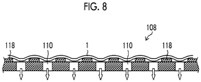
- Fig. 8 is a schematic view illustrating the absorption of the elastic deformation of the paper 1.
- an arrangement pattern (hereinafter simply referred to as the pattern of the ceramic jacket 108) of the suction holes 110 and projections 118 that are disposed on the ceramic jacket 108 greatly influences reading of the in-line sensor 62. That is, as the absorption amount of the deformation of the paper 1 increases, the radiation angle of light to a portion that is being deformed varies, and reading cannot be performed normally. Moreover, an influence such that the pattern of the ceramic jacket 108 is visible through the paper 1 is also added, and the reading unevenness corresponding to the pattern of the ceramic jacket 108 occurs. An abnormal value is output if correction of the printing unit or detection of an image defect is performed using the read image data in which this unevenness has occurred. Due to this problem, the pattern of the ceramic jacket 108 cannot be optimized for the transportability of the paper 1.
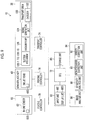
- Fig. 9 is a block diagram illustrating an electrical configuration of the ink jet printing apparatus 10.
- the ink jet printing apparatus 10 includes a central processing unit (CPU) 72, a transport controller 74, the printing controller 76, a reading controller 78, a storage unit 80, a user interface 82, an image processing unit 84, and the like in addition to the aforementioned transport unit 30, printing unit 40, and reading unit 60.
- CPU central processing unit
- the transport unit 30 includes the transport drum 100, a rotary encoder 122, a signal generation unit 124, the vacuum pump 126, and suction mechanisms 128-1 to 128-10.
- the rotary encoder 122 outputs an encoding signal according to the rotational angle of the transport drum 100.
- the signal generation unit 124 generates and outputs a PageSync signal that is a printing timing signal in which a timing of when the paper 1 passes through the printing position Pw is defined as L(0) level and the other timings are defined as H(1) level, on the basis of the encoding signal of the rotary encoder 122.
- the vacuum pump 126 (an example of a vacuuming unit) is a pump that vacuums and evacuates the inside of the vacuum flow passage (not illustrated) of the transport drum 100.
- the suction mechanisms 128-1 to 128-10 controls the suction pressure (an example of a suction force per unit area) of the suction holes 110 on the transport surface 102.
- the transport drum 100 can transport two sheets of the paper 1 in one rotation.
- the transport surface 102 of the transport drum 100 has an A surface side and a B surface side that transports the paper 1, respectively.
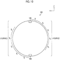
- the A surface side has a plurality of regions A 1 , A 2 , A 3 , A 4 , and A 5 that are split in one dimension in a direction orthogonal to the transport direction of the paper 1.
- the B surface side of the transport surface 102 has a plurality of regions B 1 , B 2 , B 3 , B 4 , and B 5 that are split in one dimension in the direction orthogonal to the transport direction of the paper 1.
- the suction mechanisms 128-1 to 128-10 correspond to the regions A 1 , A 2 , A 3 , A 4 , A 5 , B 1 , B 2 , B 3 , B 4 , and B 5 , respectively, and are configured to be capable of controlling the suction pressure of the suction holes 110 in each region.
- a valve (not illustrated) in each of the paths between the vacuum pump 126 and the vacuum flow passage (not illustrated)
- the drum suction holes 116, and the suction holes 110 in each region and by controlling this valve, the suction pressure of the suction holes 110 in each region can be controlled.
- the CPU 72 generally controls the respective parts of the ink jet printing apparatus 10.
- the transport controller 74 controls the rotation of the transport drum 100 and the evacuation of the vacuum pump 126. Additionally, the transport controller 74 controls the suction mechanisms 128-1 to 128-10 provided corresponding to the respective regions, respectively, thereby controlling the suction pressure of the suction holes 110 of the transport drum 100 in each region of the transport surface 102, and controlling the suction pressure at least at the reading position P R .
- the printing controller 76 controls the ink jet heads 42M, 42K, 42C, and 42Y of the printing unit 40 on the basis of the image data stored in the storage unit 80, and causes an image to be printed on the paper 1.
- the reading controller 78 controls the in-line sensor 62 of the reading unit 60, and causes an image recorded on the recording surface of the paper 1 to be read.
- the image data for performing printing on the paper 1 is stored in the storage unit 80. Additionally, the read image data acquired by the in-line sensor 62 is stored.
- the user interface 82 includes an input unit 82I and a display unit 82D that allow a user to operate the ink jet printing apparatus 10.
- a touch panel which is constituted of the display unit 82D serving as a display that displays image data and various kinds of information, and an input unit 82I serving as a control panel of which the whole surface is transparent and is superposed on the display and which receives the input from a user, is used.
- the user can operate the user interface 82, thereby causing the ink jet printing apparatus 10 to print a desired image.
- the image processing unit 84 includes an image analysis unit 86, a sensitivity correction unit 88, a non-discharge correction unit 90, and a density correction unit 92.
- the image analysis unit 86 analyzes the read image data acquired from the in-line sensor 62.
- the sensitivity correction unit 88 corrects the sensitivity of the photoelectric conversion elements 62S of the in-line sensor 62 on the basis of analysis results of the image analysis unit 86.
- the non-discharge correction unit 90 identifies a defective nozzle that is a nozzle 48 with abnormal discharge of ink, such as bending or non-discharge, from the ink jet heads 42M, 42K, 42C, and 42Y, on the basis of the analysis results of the image analysis unit 86, stops the discharge from the defective nozzle, and corrects the printing unit 40 by correcting input image data so as to perform printing using a nozzle 48, serving as an alternative nozzle, adjacent to the defective nozzle.
- ink such as bending or non-discharge
- the density correction unit 92 acquires variations in density regarding the respective nozzles 48 of the ink jet heads 42M, 42K, 42C, and 42Y on the basis of the analysis results of the image analysis unit 86, and corrects the drive conditions of the piezoelectric actuator 48S in each nozzle 48.
- the image processing unit 84 may not be built in the ink jet printing apparatus 10, and may be constituted as a computer (not illustrated) that is communicably connected to the ink jet printing apparatus 10. Additionally, an image for performing printing from the computer (not illustrated) may be acquired.
- Fig. 11 is a flowchart illustrating steps of a printing method related to the first embodiment.
- a test chart is printed on the paper 1 to be transported on the A surface side of the transport surface 102.
- Step S1 an example of a suction force per unit area
- Fig. 12 is a view illustrating a state in which the paper 1 is fed from the paper feed unit 20 to the transport unit 30.
- a PageSync signal is an L level.
- the printing unit 40 detects the L level of the PageSync signal, and prints an image on the paper 1 (Step S2, an example of a printing step).
- a test chart for detecting non-discharge and a test chart for detecting density unevenness are printed. Since the paper 1 is suctioned and transported with a suction pressure of 20 kPa, the paper 1 can be stably transported, and a test chart can be appropriately printed.
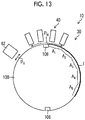
- Fig. 13 is a view illustrating a state in which a leading end side of the paper 1 to be transported has reached the printing position P W .
- Step S3 an example of a control step
- Fig. 14 is a view illustrating a state in which the region A 1 has reached the reading position P R .
- the suction pressure of the region A 1 is set to 10 kPa
- the suction pressure of the regions A 2 , A 3 , A 4 , and A 5 is set to 20 kPa.
- Fig. 15 is a view illustrating a state in which the region A 1 of the paper 1 passed through the reading position P R and the regions A 2 and A 3 have reached the reading position P R .
- the suction pressure of the regions A 2 and A 3 is set to 10 kPa
- the suction pressure of the regions A 1 , A 4 , and A 5 is set to 20 kPa.
- Fig. 16 is a timing chart illustrating changes in the PageSync signal and changes in the suction pressures of the respective regions A 1 , A 2 , A 3 , A 4 , and A 5 .
- the in-line sensor 62 starts reading 100 microseconds after falling of the PageSync signal is input. Additionally, the suction mechanism 128-1 makes the suction pressure gradually smaller 80 microseconds after the falling of the PageSync signal is input. Thereafter, the suction mechanisms 128-2 to 128-5 make the suction pressure small in order.
- the suction pressure is gradually changed from 20 kPa, which is a standard value in a case where the thickness of the paper 1 is less than 0.2 mm, to 10 kPa. Additionally, the suction mechanisms 128-1 to 128-5 gradually return the suction pressure to 20 kPa 40 microseconds after the suction pressure is made small.
- the suction pressure may not be gradually changed but may be rapidly changed. Additionally, the suction pressure may be made small only at the reading position. Hence, the suction pressure may be changed from 20 kPa to 10 kPa 100 microseconds after the falling of the PageSync signal is input.
- the transport controller 74 controls the suction mechanisms 128-1 to 128-5, thereby setting the suction pressure of a region before reaching the reading position P R or after passing through the reading position P R to 20 kPa that is the first suction pressure, and setting the suction pressure of a region while passing through the reading position P R to 10 kPa that is the second suction pressure lower than the first suction pressure.
- the in-line sensor 62 reads a margin and a test chart of the paper 1 at the reading position P R through the control of the reading controller 78, and converts the read margin and test chart into read image data (Step S4, an example of a reading step).
- the paper 1 is suctioned and transported with the suction pressure of 10 kPa smaller than the suction pressure at the printing position P W .
- the acquired read image data is not influenced by the pattern of the ceramic jacket 108.
- Step S5 correction of the printing unit 40 and/or the reading unit 60 is performed on the basis of a reading result of the reading unit 60 (Step S5, an example of a correction step), and the processing of a final flowchart is ended.
- the sensitivity correction unit 88 corrects the sensitivity of the photoelectric conversion element 62S of the in-line sensor 62 on the basis of a reading result of the margin of the paper 1.
- the non-discharge correction unit 90 corrects the input image data on the basis of a reading result of the test chart for detecting non-discharge, thereby correcting the printing unit 40.
- the density correction unit 92 corrects the input image data on the basis of a reading result of the test chart for detecting density unevenness, thereby correcting the drive conditions of the piezoelectric actuator 48S provided for each nozzle 48.
- Figs. 17 and 18 are views illustrating the read image data of an image with a uniform density in the in-line sensor 62
- Fig. 17 illustrates an enhanced image in a case where the suction pressure is 20 kPa
- Fig. 18 illustrates an enhanced image in a case where the suction pressure is 10 kPa.
- the pattern of the ceramic jacket 108 is visually recognized in the read image data.
- the suction pressure is 20 kPa
- the pattern of the ceramic jacket 108 is not visually recognized in the read image data.
- the pattern of the ceramic jacket 108 can be optimized for the transportability of the paper 1, and the transport performance, and the reading and the correction performance can be made compatible with each other.
- the suction pressure of a region before reaching the reading position P R and after passing through the reading position P R is set to the first suction pressure and the suction pressure of a region while passing through the reading position P R is set to the second suction pressure lower than the first suction pressure.
- the suction pressure of a region before reaching the reading position P R may be set to the first suction pressure
- the suction pressure of a region while passing through the reading position P R and after the reading position P R may be set to the second suction pressure lower than the first suction pressure.
- an aspect in which the second suction pressure is set to zero, that is, suction is stopped is also possible.
- the printing for correction in which the reading unit 60 reads an image of a test chart of which a reading result is used by at least one of the sensitivity correction unit 88, the non-discharge correction unit 90, or the density correction unit 92 has been described.
- the paper 1 is stably transported by performing the entire surface suction with 20 kPa that is normal suction pressure.
- the correction performed in the present embodiment is not limited to the sensitivity correction, the non-discharge correction, and the density correction, and can also be applied during correction printing of installation adjustment.
- the relationships between the pixel positions of the read image data of the in-line sensor 62, and the numbers (positions) of the respective nozzles 48 of ink jet heads 42M, 42K, 42C, and 42Y are calculated.
- the positions of the nozzles 48 can be identified from the read image data of the in-line sensor 62, and the subsequent detection or correction is possible.
- the non-discharge correction optimization is processing in which correction is performed by adjusting the discharge amount of a nozzle 48 adjacent to a defective nozzle in the non-discharge correction unit 90 in a case where the defective nozzle has occurred, but the amount of adjustment in this case is calculated in advance.
- Fig. 19 is a block diagram illustrating an electrical configuration of an ink jet printing apparatus 12 related to a second embodiment.
- the portions that are in common with those of the block diagram illustrated in Fig. 9 will be designated by the same reference signs and the detailed description thereof will be omitted.
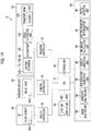
- the ink jet printing apparatus 12 includes suction mechanisms 128-1 to 128-30, an ink amount calculation unit 94, a suction pressure determination unit 96, and a defect detection unit 98.
- the suction mechanisms 128-1 to 128-30 control the suction pressure of the suction holes 110 in the transport surface 102.
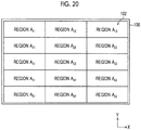
- Fig. 20 is a view illustrating an A surface side of a transport surface 102 of a transport drum 100.
- the A surface side of the transport surface 102 has a plurality of regions A 11 , A 12 , A 13 , A 21 , A 22 , A 23 , A 31 , A 32 , A 33 , A 41 , A 42 , A 43 , A 51 , A 52 , and A 53 that are two-dimensionally split into a total of 15 divisions of 3 divisions in the direction orthogonal to the transport direction of the paper 1 and 5 divisions in the transport direction of the paper 1.
- the suction mechanisms 128-1 to 128-15 correspond to regions split into 15, respectively, and are configured to be capable of controlling the suction pressures of the suction holes 110 in the respective regions.
- a B surface side of the transport surface 102 is also two-dimensionally split into 15 divisions and the suction mechanisms 128-16 to 128-30 correspond to regions split into 15, respectively, and are configured to be capable of controlling the suction pressure of the suction holes 110 in each region.
- the ink amount calculation unit 94 calculates the amount of ink of an image to be printed.
- an overall image to be printed on the paper 1 is split into a total of 15 divisions of 3 divisions in the direction orthogonal to the transport direction of the paper 1 and 5 divisions in the transport direction of the paper 1, and the amounts of ink in the respective split regions are calculated, respectively.
- the amount of ink in each region is the total of the amount of ink discharged from each nozzle 48 to each region in a case where printing is performed in the printing unit 40.
- the suction pressure determination unit 96 determines the suction pressures in a case where the respective regions split into 15 are read in the reading unit 60 on the basis of the amounts of ink calculated in the ink amount calculation unit 94.
- the defect detection unit 98 detects a defect of a printed image on the basis of the analysis results of the image analysis unit 86.
- the image analysis unit 86 analyzes the printed image by comparing the read image data of the in-line sensor 62 with the image data stored in the storage unit 80.
- Fig. 21 is a flowchart illustrating steps of a printing method related to the second embodiment.
- a case where an image for final printing is printed on the paper 1 to be transported on the A surface side of the transport surface 102 will be described.
- the ink amount calculation unit 94 acquires image data for performing printing on the paper 1 from the storage unit 80 (Step S11).
- the image data herein is image data for final printing for the printed matter to be commercially available.
- the ink amount calculation unit 94 calculates the amounts of ink in the respective regions split into a total of 15 divisions of 3 divisions in the direction orthogonal to the transport direction of the paper 1 and 5 divisions in the transport direction of the paper 1, respectively, regarding the acquired image data (Step S12).
- the amounts of ink in the respective regions may be calculated, and the calculated amounts of ink may be stored in the storage unit 80 with the image data.
- the suction pressure determination unit 96 determines the suction pressures of the respective regions in a case of being read in the reading unit 60, on the basis of the amounts of ink calculated in Steps 12 (Step S 13).
- the amounts of ink are divided into three levels, and according to the levels, any suction pressure of 20 kPa, 15 kPa and 10 kPa is set such that the suction pressure is made lower as a region with a smaller amount of ink.
- suction is performed with a higher suction pressure in a region with a relatively larger amount of ink, and suction is performed with a lower suction pressure in a region with a relatively smaller amount of ink.
- the suction mechanisms 128-1 to 128-30 may determine the suction pressure in consideration of not only the amounts of ink in the respective corresponding regions but also the amounts of ink in the regions adjacent to the respective regions.
- the paper 1 is suctioned from the respective suction holes 110 with 20 kPa that is the first suction pressure, and transport is started (Step S14). Moreover, if the paper 1 reaches the printing position Pw, the printing unit 40 prints a final printing image on the paper 1 (Step S15). Since the paper 1 is suctioned and transported with a suction pressure of 20 kPa, the paper 1 can be stably transported, and an image can be appropriately printed.
- the transport controller 74 changes the suction pressure of the suction holes 110 at the reading position P R to the suction pressure (an example of a second suction force per unit area) determined in Step S 13, and suctions the paper 1 (Step S16).
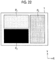
- Fig. 22 is a view illustrating an example of an image printed on the paper 1.
- a region P 1 where the amount of ink is relatively small a region P 2 where the amount of ink is relatively large, and a region P 3 where the amount of ink is relatively medium are provided.
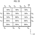
- Fig. 23 is a view illustrating the suction pressures, in a case where the respective regions split into 15 on the A surface side of the transport surface 102 are read in the reading unit 60, which are determined by the suction pressure determination unit 96.
- the suction pressures of the regions A 11 , A 12 , A 13 , A 21 , A 22 , A 23 , A 31 , A 32 , A 33 , A 41 , A 42 , A 43 , A 51 , A 52 , and A 53 are 10 kPa, 10 kPa, 15 kPa, 10 kPa, 10 kPa, 15 kPa, 15 kPa, 20 kPa, 15 kPa, 20 kPa, 20 kPa, 20 kPa, 20 kPa, 20 kPa, 20 kPa, 20 kPa, 20 kPa, 20 kPa, 20 kPa, and 20 kPa, respectively.
- the regions A 13 , A 23 , A 33 , A 43 , and A 53 respectively correspond to the region P 3 where the amount of ink is relatively medium, the amounts of ink are almost the same but the suction pressures are set to 15 kPa, 15 kPa, 15 kPa, 20 kPa, and 20 kPa, respectively, and not the same suction pressure. These values are different from each other depending not only on the amounts of ink in the respective regions but also on the balance between the suction pressures in the regions adjacent to the respective regions in the X direction.
- the transport controller 74 controls the suction pressures using a PageSync signal that is used as a reading start trigger signal by the in-line sensor 62. That is, the in-line sensor 62 starts reading 100 microseconds after falling of the PageSync signal is input, while the suction mechanisms 128-1 to 128-3 set the suction pressures of the region A 11 , A 12 , and A 13 to gradually determine suction pressures 80 microseconds after the falling of the PageSync signal is input. Moreover, the suction mechanisms 128-1 to 128-3 gradually return the suction pressures of the regions A 11 , A 12 , and A 13 to the first suction pressure 40 microseconds after the suction pressures are changed.
- a PageSync signal that is used as a reading start trigger signal by the in-line sensor 62. That is, the in-line sensor 62 starts reading 100 microseconds after falling of the PageSync signal is input, while the suction mechanisms 128-1 to 128-3 set the suction pressures of the region A 11 , A 12 , and A 13
- the suction mechanisms 128-4 to 128-6, 128-7 to 128-9, 128-10 to 128-12, and 128-13 to 128-15 sequentially control the suction pressures of the regions A 21 , A 22 , and A 23 , the regions A 31 , A 32 , and A 33 , the regions A 41 , A 42 , and A 43 and the regions A 51 , A 52 , and A 53 .
- the suction pressure at the reading position P R is made smaller in a region where the amount of ink to be applied to the paper 1 is smaller. Additionally, the timing of when the suction pressure is made smaller may be made early in a region where the amount of ink is smaller. For example, in regions where the amount of ink is relatively large, the suction pressure is made gradually small 80 microseconds after the falling of the PageSync signal is input, and in regions where the amount of ink is relatively small, the suction pressure may be made gradually small 40 microseconds after the falling of the PageSync signal is input.
- the in-line sensor 62 reads the image for final printing printed on the paper 1 at the reading position P R through the control of the reading controller 78, and converts the image into read image data (Step S17).
- the suction pressure becomes small according to the amount of ink, the influence of the read image data caused by the pattern of the ceramic jacket 108 is eliminated.
- a defect of the image printed on the paper 1 is detected on the basis of the read image data of the in-line sensor 62 and the image data for final printing of the storage unit 80 (Step S18), and the processing of a final flowchart is ended.
- a defect of an image is detected by calculating a difference image between the read image data and the image data for final printing and analyzing the difference image.
- the paper 1 since the paper 1 is suctioned and transported with a suction pressure of 20 kPa, the paper 1 can be stably transported, and the final printing image can be appropriately printed. Additionally, by lowering the suction force per unit area according to the amount of ink at least at the reading timing of the reading unit 60, the influence caused by the pattern of the ceramic jacket 108 can be eliminated, the image recorded on the paper 1 can be appropriately read, and the reading and the correction performance during test chart printing can be ensured. Hence, the pattern of the ceramic jacket 108 can be optimized for the transportability of the paper 1, and the transport performance, and the reading and the correction performance can be made compatible with each other.
- Fig. 24 is a flowchart illustrating steps of a printing method related to a third embodiment.
- a user corrects suction pressures and/or the change timings of the suction pressures in the ink jet printing apparatus 12.
- Printing and reading of image data are performed similar to the second embodiment (Step S21).
- Step S22 the user visually evaluates the image printed on the paper 1 in Step S21 (Step S22).
- the user displays read image data on the user interface 82 in a case where the unevenness (appears in full width at an equal pitch) considered to be a pattern of the ceramic jacket 108 is viewed (Step S23).
- the user adjusts at least one of contrast, a maximum value, or a minimum value by the user interface 82 with respect to the displayed read image data, and displays the read image data in an enhanced manner (Step S24).
- the read image data displayed in 8 bits (0 to 255) is displayed as grayscale values of 0 to 50.
- the user compares the image that is displayed in an enhanced manner with the image for final printing of the paper 1, and confirms whether or not the unevenness actually corresponds to the reflection of the pattern of the ceramic jacket 108. If the unevenness corresponds to the reflection, adjustment of the suction pressures and/or the suction timings is performed (Step S25, Step S26).
- the adjustment of the suction pressures is carried out by displaying a two-dimensional array of the suction pressures illustrated in Fig. 23 on the user interface 82 (an example of a display unit) and by a user changing corresponding positions with the user interface 82 (an example of an adjustment unit). If it is assumed that unevenness has occurred at a lower right portion of the paper 1 in an example illustrated in Fig. 23 , the suction pressures in the regions A 43 and A 53 are changed from 20 kPa to 15 kPa.
- the adjustment of the suction timings about four levels of slightly late, standard, slightly early, and early are selectively displayed in advance on the user interface 82 so that the user can appropriately change the levels.
- the occurrence of the unevenness can be reduced by advancing the timing of when the suction pressures are made small.
- the timing of when the suction pressure is made small may be delayed.
- the influence by the pattern of the ceramic jacket 108 can be appropriately eliminated from the read image data by performing the adjustment of the suction pressures and/or suction timings.
- the transport unit 30 has been described up to now by using an example in which the transport drum 100 holding the paper 1 is provided on the transport surface 102, the transport unit 30 is not limited to the drum transport, and for example, belt transport or the like may be used.
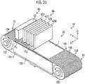
- Fig. 25 is a schematic view illustrating an overall configuration of an ink jet printing apparatus 14 related to a fourth embodiment.
- the ink jet printing apparatus 14 is a single path type line printer that prints an image on the recording surface of the paper 1, and includes the paper feed unit 20, the transport unit 30, the printing unit 40, the reading unit 60, the paper ejection unit 70, and the like.
- the transport unit 30 has a structure in which an endless transport belt 154 is wound between a roller 150 and a roller 152.
- the transport belt 154 is formed of rubber and/or urethane. Additionally, the transport belt 154 has a width in the X direction larger than the width of the paper 1 in the X direction, and an outer peripheral surface becomes a transport surface 160.
- the transport surface 160 is configured so as to form a horizontal plane at the printing position Pw that is a position that faces the printing unit 40 and at the reading position P R that is a position that faces the reading unit 60.
- the transport unit 30 transports the paper 1 held on the transport surface 160 of the transport belt 154 to the printing unit 40 and the reading unit 60 in this order by transmitting the power of a motor (not illustrated) to at least one of the roller 150 or the roller 152.
- the suction mechanisms 128-1 to 128-2 are provided inside the transport belt 154 in the transport unit 30. Additionally, a large number of suction holes 156 passes through the transport belt 154, and projections 158 are formed on the transport surface 160 side of a portion where the suction holes 156 are not formed. By vacuuming the gas in the suction holes 156 of the transport belt 154 using the suction mechanisms 128 to 128-2, and bringing the suction holes into a negative pressure, the paper 1 has the opposite surface of the recording surface suctioned on and held by the transport surface 160.
- the printing unit 40 includes the four ink jet heads 42M, 42K, 42C, and 42Y
- the ink jet heads 42M, 42K, 42C, and 42Y are respectively disposed sequentially from an upstream side at regular intervals along the transport path of the paper 1 on the transport belt 154.
- the configuration of the ink jet heads 42M, 42K, 42C, and 42Y is the same as that of the first embodiment.
- the ink jet heads 42M, 42K, 42C, and 42Y discharge ink from the respective nozzles 48 to the recording surface of the paper 1 transported to the printing position Pw, and print an image on the recording surface of the paper 1.
- the reading unit 60 is disposed on a downstream side of the printing unit 40 on the transport path of the transport belt 154.
- the reading unit 60 includes the in-line sensor 62.
- the configuration of the in-line sensor 62 is also the same as that of the first embodiment.
- the in-line sensor 62 reads the recording surface of the paper 1 transported to the reading position P R , and converts the read results into read image data.
- the distance in a Y direction between the printing unit 40 and the reading unit 60 is shorter than the length of the paper 1 in the Y direction. Hence, the paper 1 during transport may straddle both of the printing position P W and the reading position P R .
- the suction mechanism 128-1 suctions the paper 1 at the printing position P W and the suction mechanism 128-2 suctions the paper 1 at the reading position P R .
- the suction pressures of both the suction mechanism 128-1 and the suction mechanism 128-2 are set to 20 kPa that is the first suction pressure in a case where an image for final printing is printed, and the suction pressure of the suction mechanism 128-1 is set to 20 kPa that is the first suction pressure and the suction pressure of the suction mechanism 128-2 is set to 10 kPa that is the second suction pressure in a case where a test chart is printed. Accordingly, the influence caused by the pattern consisting of the suction holes 156 and the projections 158 of the transport belt 154 is eliminated from the read image data acquired by the in-line sensor 62.
- the pattern of the ceramic jacket 108 can be optimized for the transportability of the paper 1, and the transport performance, and the reading and the correction performance can be made compatible with each other.
- suction holes that are concave shapes and the projections that are convex shapes are provided on the transport surface
- at least one shape of a plurality of concave shapes or a plurality of convex shapes may be provided on the transport surface.
Landscapes
- Ink Jet (AREA)
- Accessory Devices And Overall Control Thereof (AREA)
- Feeding Of Articles By Means Other Than Belts Or Rollers (AREA)
- Handling Of Sheets (AREA)
Abstract
Description
- The present invention relates to a printing apparatus and a printing method, and particularly, to a printing apparatus and a printing method that suctions and transports a recording medium.
- In printing apparatuses, suctioning a recording medium from a back surface thereof to transport the recording medium is performed. In such printing apparatuses, a technique of changing a suction force according to the contents of processing and/or the state of the recording medium is known.
- For example,
JP2015-123590A - Additionally,
JP2011-195295A - The print media in
JP2015-123590A JP2011-195295A - In the printing apparatuses, reading an image printed on a recording medium by a printhead, obtaining the amount of correction of a printing property of the printhead from the read image data, and correcting the printhead with the obtained amount of correction are performed. However, in a case where a plurality of concave shapes and/or convex shapes are given on a supporting surface that supports the recording medium, the shapes appear on the front surface of a suctioned recording medium. Accordingly, there is a case where the read image data does not become suitable data and the amount of correction of the printing property cannot be appropriately obtained.
- The invention has been made in view of such circumstances, and an object thereof is to provide a printing apparatus and a printing method that allow transport performance, and reading and correction performance to be compatible with each other.
- In order to achieve the above object, one aspect of a printing apparatus is a printing apparatus comprising a supporting part that brings an opposite surface of a recording surface of a recording medium into contact with a supporting surface having shapes of at least one of a plurality of concave shapes or a plurality of convex shapes to support the recording surface; a suction unit that suctions the recording medium supported by the supporting part with a first suction force per unit area on the supporting surface; a transport unit that transports the recording medium suctioned on the supporting surface along a transport path; a printing unit that is disposed to face the transport path, prints an image based on input data on the recording surface at a printing position of the transport path; a reading unit that is disposed to face the transport path on a downstream side of the transport path with respect to the printing unit, and reads the recording surface at a reading position of the transport path; a correction unit that corrects at least one of the printing unit or the reading unit on the basis of a reading result of the reading unit; and a controller that controls a suction force per unit area of the suction unit at the reading position and that suctions the recording medium on the suction unit with a second suction force per unit area smaller than the first suction force per unit area or stops suction of the suction unit, at least in a case where the reading unit reads an image using a reading result in the correction unit.
- According to this aspect, the recording medium is suctioned with the first suction force per unit area, and the recording medium is suctioned on the suction unit with the second suction force per unit area smaller than the first suction force per unit area or the suction of the suction unit is stopped, at least in a case where the reading unit reads the image using the reading result in the correction unit. Thus, the recording medium can be stably transported, and the reading result used in the correction unit is not influenced by the concave shapes and the convex shapes of the supporting surface. Hence, transport performance, and reading, and correction performance can be made compatible with each other.
- It is preferable that the printing unit includes an ink jet head that applies ink to print an image on the recording surface of the recording medium, and a defect detection unit that detects a defect of the image on the basis of the reading result of the reading unit, and the controller makes the suction force per unit area of the suction unit at the reading position smaller in a region where the amount of ink to be applied to the recording surface is smaller, in a case where the reading unit reads the image using the reading result in the defect detection unit. Accordingly, the image defect can be appropriately detected without the reading result being influenced by the concave shapes and the convex shapes of the supporting surface.
- It is preferable that the controller makes the suction force at the reading position smaller by advancing a timing of when the suction force per unit area of the suction unit is made smaller, as the amount of ink of the printed image becomes smaller. Accordingly, the image defect can be appropriately detected without the reading result being influenced by the concave shapes and the convex shapes of the supporting surface.
- It is preferable that the supporting surface has a plurality of regions split in a direction orthogonal to a transport direction of the recording medium, and the controller controls the suction force per unit area of the suction unit in each of the plurality of regions. Accordingly, the suction force can be appropriately controlled.
- It is preferable that the supporting surface has a plurality of regions split in a transport direction of the recording medium and a direction orthogonal to the transport direction of the recording medium, and the controller controls the suction force per unit area of the suction unit in each of the plurality of regions. Accordingly, the suction force can be appropriately controlled.
- It is preferable that the printing apparatus according to any one of claims further comprises a display unit that displays the reading result of the reading unit in an enhanced manner; and an adjustment unit that allows a user to adjust at least one of the suction force per unit area of the suction unit at the reading position or a timing of when the suction force is made small. Accordingly, the influence caused by the concave shapes and the convex shapes of the supporting surface in the reading result can be appropriately eliminated.
- It is preferable that the suction unit includes a vacuuming unit that vacuums gas from a suction hole formed in the supporting surface to suction the recording medium. Even in the suction unit including such a suction unit, the influence caused by the concave shapes and the convex shapes of the supporting surface on the reading result can be appropriately eliminated.
- It is preferable that the transport unit includes a transport drum that rotates the recording medium suctioned on an outer peripheral surface to be transported along the transport path. Additionally, it is preferable that the supporting surface includes a jacket having shapes of at least one of the plurality of concave shapes or the plurality of convex shapes. Even in such a transport unit, the influence caused by the concave shapes and the convex shapes of the supporting surface of the reading unit can be appropriately eliminated.
- It is preferable that the reading unit includes a plurality of photoelectric conversion elements, and the correction unit that corrects sensitivity of the plurality of photoelectric conversion elements on the basis of the reading result of the reading unit. Accordingly, since the influence caused by the concave shapes and the convex shapes of the supporting surface on the reading result can be appropriately eliminated, the sensitivity of the plurality of photoelectric conversion elements can be appropriately corrected.
- It is preferable that the printing unit prints an image by a plurality of recording elements, and the correction unit corrects input data corresponding to the recording elements on the basis of the reading result of the reading unit. Moreover, the printing unit may print an image by a plurality of recording elements, and the correction unit may correct drive conditions of the plurality of recording elements on the basis of the reading result of the reading unit. Accordingly, since the influence caused by the concave shapes and the convex shapes of the supporting surface on the reading result can be appropriately eliminated, the input data corresponding to the plurality of recording elements and/or the drive conditions of the plurality of recording elements can be appropriately corrected.
- In order to achieve the above object, one aspect of a printing method is a printing method comprising a suction step of bringing an opposite surface of a recording surface of a recording medium into contact with a supporting surface having shapes of at least one of a plurality of concave shapes or a plurality of convex shapes to support the recording surface and suctioning the supported recording medium with a suction force per a first unit area on the supporting surface; a transport step of transporting the recording medium suctioned on the supporting surface along a transport path; a printing step of printing an image based on input data on the recording surface at a printing position of the transport path by a printing unit disposed to face the transport path;a reading step of reading the recording surface at a reading position of the transport path by a reading unit disposed to face the transport path on a downstream side of the transport path with respect to the printing unit; a correction step of correcting at least one of the printing unit or the reading unit on the basis of a reading result of the reading step; and a control step of controlling a suction force per unit area of the suction step at the reading position and suctioning the recording medium in the suction step with a suction force per a second unit area smaller than the suction force per the first unit area or stopping suction of the suction step, at least in a case where an image using a reading result in the correction step is read in the reading step.
- According to this aspect, the recording medium is suctioned with the first suction force per unit area, and the recording medium is suctioned on the suction unit with the second suction force per unit area smaller than the first suction force per unit area or the suction of the suction unit is stopped, at least in a case where the reading unit reads the image using the reading result in the correction unit. Thus, the recording medium can be stably transported, and the reading result used in the correction unit is not influenced by the concave shapes and the convex shapes of the supporting surface. Hence, transport performance, and reading, and correction performance can be made compatible with each other.
- According to the invention, transport performance, and reading, and correction performance can be made compatible with each other.
-
-
Fig. 1 is a schematic view illustrating an overall configuration of an ink jet printing apparatus. -
Fig. 2 is a view of an ink jet head as seen from a nozzle surface side. -
Fig. 3 is a partially enlarged view ofFig. 2 . -
Fig. 4 is a perspective view illustrating an overall structure of a transport drum. -
Fig. 5 is an exploded perspective view illustrating an internal structure of the transport drum. -
Fig. 6 is a view illustrating a front surface of a ceramic jacket. -
Fig. 7 is a 7-7 sectional view ofFig. 6 . -
Fig. 8 is a schematic view illustrating absorption of elastic deformation of paper. -
Fig. 9 is a block diagram illustrating an electrical configuration of the ink jet printing apparatus. -
Fig. 10 is a view illustrating a plurality of split regions of a transport surface of the transport drum. -
Fig. 11 is a flowchart illustrating steps of a printing method. -
Fig. 12 is a view illustrating a state in which paper is fed from a paper feed unit to a transport unit. -
Fig. 13 is a view illustrating a state in which a leading end side of paper to be transported has reached a printing position. -
Fig. 14 is a view illustrating a state in which a region A1 has reached a reading position. -
Fig. 15 is a view illustrating a state in which regions A2 and A3 have reached the reading position. -
Fig. 16 is a timing chart illustrating changes in a PageSync signal and changes in the suction pressures of respective regions A1, A2, A3, A4, and A5. -
Fig. 17 is read image data of a density unevenness correction test chart. -
Fig. 18 is read image data of a density unevenness correction test chart. -
Fig. 19 is a block diagram illustrating an electrical configuration of an ink jet printing apparatus. -
Fig. 20 is a view illustrating a transport surface of a transport drum. -
Fig. 21 is a flowchart illustrating steps of a printing method. -
Fig. 22 is a view illustrating an example of an image printed on paper. -
Fig. 23 is a view illustrating suction pressures of respective regions of the transport surface. -
Fig. 24 is a flowchart illustrating steps of a printing method. -
Fig. 25 is a schematic view illustrating an overall configuration of an ink jet printing apparatus. - Preferred embodiments of the invention will be described below in detail according to the accompanying drawings.
-
Fig. 1 is a schematic view illustrating an overall configuration of an inkjet printing apparatus 10 related to the present embodiment. As illustrated in this drawing, the inkjet printing apparatus 10 is a single path type line printer that prints an image on a recording surface of paper 1 (an example of a recording medium), and includes apaper feed unit 20, atransport unit 30, aprinting unit 40, areading unit 60, apaper ejection unit 70, and the like. - The
transport unit 30 includes atransport drum 100. Thetransport drum 100 has a transport surface 102 (an example of a supporting surface) and arotary shaft 104 that holds thepaper 1. Additionally, twogrippers 106 for gripping a leading end of thepaper 1 are provided at positions that face each other with therotary shaft 104 of thetransport surface 102 interposed therebetween. - Additionally, a large number of suction holes 110 (refer to
Fig. 4 ) is formed in a fixed pattern on the transport surface of thetransport drum 100. Thepaper 1 introduced from thepaper feed unit 20 has its leading end gripped by thegrippers 106 and is wound around thetransport surface 102 of thetransport drum 100 that is rotating. Moreover, by vacuuming thepaper 1 fromsuction holes 110, a surface opposite to the recording surface is suctioned on and held by thetransport surface 102 of thetransport drum 100. Thetransport drum 100 holds thepaper 1 on thetransport surface 102 and rotates in the counterclockwise direction inFig. 1 around therotary shaft 104, thereby transporting thepaper 1 along a transport path. Thepaper 1, which has passed through a printing position Pw that is a position on a transport path which faces theprinting unit 40 and a reading position PR that is a position that faces thereading unit 60, is discharged from thepaper ejection unit 70. Since thetransport drum 100 includes thegrippers 106 in the two positions, thetransport drum 100 can transport two sheets of thepaper 1 in one rotation. - The
printing unit 40 includes four ink jet heads 42M, 42K, 42C, and 42Y, and the ink jet heads 42M, 42K, 42C, and 42Y are respectively disposed sequentially from an upstream side at regular intervals along the transport path of thepaper 1 on thetransport drum 100. Additionally, the ink jet heads 42M, 42K, 42C, and 42Y respectively includenozzle surfaces transport drum 100, and a plurality of nozzles 48 (refer toFig. 3 ) for discharging magenta ink (M ink), black ink (K ink), cyan ink (C ink), and yellow ink (Y ink) respectively are formed over the full width of thepaper 1 in therespective nozzle surfaces - The respective ink jet heads 42M, 42K, 42C, and 42Y are held such that the
respective nozzle surfaces respective nozzle surfaces transport drum 100. - Through the control of a printing controller 76 (refer to
Fig. 9 ) that generally controls printing of the inkjet printing apparatus 10, the ink jet heads 42M, 42K, 42C, and 42Y discharge ink from therespective nozzles 48 on the basis of input image data (an example of input data) and prints an image on the recording surface of thepaper 1 transported on thetransport drum 100. - The
reading unit 60 is disposed on a downstream side of theprinting unit 40 on the transport path of thetransport drum 100. Thereading unit 60 includes an in-line sensor 62. - A plurality of
photoelectric conversion elements 62S (refer toFig. 9 ) capable of reading a length corresponding to the full width of thepaper 1 are disposed in the in-line sensor 62. The in-line sensor 62 irradiates the recording surface of thepaper 1 with light in a case where thepaper 1 passes through the reading position PR, reads an image recorded on the recording surface of thepaper 1 from reflected light, and converts the image into read image data. - In addition, the distance in a transport direction between the
printing unit 40 and thereading unit 60 is shorter than the length of thepaper 1 in its transport direction. Hence, thepaper 1 during transport may straddle both of the printing position Pw and the reading position PR. - Since the ink jet heads 42M, 42K, 42C, and 42Y have the same configuration, the
ink jet head 42M will be representatively described herein.Fig. 2 is a view of theink jet head 42M as seen from thenozzle surface 44M side, andFig. 3 is a partially enlarged view ofFig. 2 . - The
ink jet head 42M has an elongated structure in which seventeen head modules 46-1 to 46-17 are connected together in an X direction, and a plurality ofnozzles 48 are disposed in two dimensions over a length corresponding to the full width of thepaper 1 on thenozzle surface 44M. Each of the plurality ofnozzles 48 includes apiezoelectric actuator 48S (refer to an example of a recording element, andFig. 9 ) as a droplet discharge element, and ink is discharged from eachnozzle 48 by driving thepiezoelectric actuator 48S. In addition, a thermal jet method or the like may be used as a method of discharging ink from thenozzle 48. - The respective head modules 46-1 to 46-17 are configured in a replaceable manner, and are supported by a head
module supporting member 50 from both sides of theink jet head 42M in its lateral direction. Additionally, both end parts of theink jet head 42M in its longitudinal direction are supported by ahead supporting member 52. -
Fig. 4 is a perspective view illustrating an overall structure of thetransport drum 100, andFig. 5 is an exploded perspective view illustrating an internal structure of thetransport drum 100. - The
transport drum 100 includes aceramic jacket 108 in which a large number of suction holes 110 are formed on a front surface constituting thetransport surface 102, and amain drum body 114 including adrum suction groove 112, and is configured such that theceramic jacket 108 is mounted on themain drum body 114. - A
drum suction hole 116 that communicates with a vacuum flow passage (not illustrated) provided inside themain drum body 114 is provided at an end part of thedrum suction groove 112 provided on a peripheral surface of themain drum body 114. -
Fig. 6 is a view illustrating a front surface (the surface constituting the transport surface 102) of theceramic jacket 108. As illustrated in this drawing, the large number of suction holes 110 (an example of concave shapes) and a large number of projections 118 (an example of convex shapes) are regularly disposed on thetransport surface 102. - Additionally,
Fig. 7 is a 7-7 sectional view ofFig. 6 . Theceramic jacket 108 is constituted of asuction hole layer 108A on the front surface side which constitutes thetransport surface 102 of thetransport drum 100, and a flow passagegroove formation layer 108B on a back surface side which comes into contact with themain drum body 114. The larger number of suction holes 110, which pass through thesuction hole layer 108A in a circular shape, are formed in thesuction hole layer 108A, and thecolumnar projections 118 are formed on thetransport surface 102 side of a portion where the suction holes 110 are not formed. - Additionally, a
jacket suction groove 120 is formed by the flow passagegroove formation layer 108B. Thejacket suction groove 120 allows thedrum suction groove 112 and eachsuction hole 110 to communicate with each other. - In addition, although the
ceramic jacket 108 in which the large number of suction holes 110 and the large number ofprojections 118 are formed is mounted on themain drum body 114, the large number of suction holes 110 and the large number ofprojections 118 may be formed in themain drum body 114 without using theceramic jacket 108. - Additionally, the suction holes 110 are not limited to those passing through the suction hole layer in a circular shape, and may pass through the suction hole layer in a quadrangular shape or a polygonal shape. Additionally, the shape of the
projections 118 is not limited to the columnar shape, and may be a semi-spherical shape (a dome shape), a quadrangular prismatic shape, and a polygonal prismatic shape. - If a vacuum pump 126 (refer to
Fig. 9 ) that communicates with the vacuum flow passage (not illustrated) is driven, the suction pressure for suctioning and holding thepaper 1 is generated in the suction holes 110 via thedrum suction groove 112 and thejacket suction groove 120. - The distance between the
transport drum 100 and the ink jet heads 42M, 42K, 42C, and 42Y is about 1.0 to 2.0 mm. Hence, if floating occurs in thepaper 1, printing may not be performed normally and also the ink jet heads 42M, 42K, 42C, and 42Y may be brought into contact with thepaper 1 and the ink jet heads 42M, 42K, 42C, and 42Y may be broken. For this reason, thepaper 1 is transported while being suctioned on thetransport surface 102. - Here, for example, in a case where a back surface is already printed, the
paper 1 shrinks partially, and it is difficult for the paper to be normally suctioned. Hence, in the inkjet printing apparatus 10, by disposing the suction holes 110 and theprojections 118 in a certain pattern in theceramic jacket 108 of thetransport drum 100, elastic deformation of thepaper 1 is absorbed, the paper is suctioned, and the transport performance is realized.Fig. 8 is a schematic view illustrating the absorption of the elastic deformation of thepaper 1. By forming concavo-convex shapes in thetransport surface 102 in this way, the deformation that thepaper 1 has can be absorbed by the concavo-convex shapes, and thepaper 1 can be brought into close contact with thetransport surface 102 without generating wrinkling or floating. - However, it was found that an arrangement pattern (hereinafter simply referred to as the pattern of the ceramic jacket 108) of the suction holes 110 and
projections 118 that are disposed on theceramic jacket 108 greatly influences reading of the in-line sensor 62. That is, as the absorption amount of the deformation of thepaper 1 increases, the radiation angle of light to a portion that is being deformed varies, and reading cannot be performed normally. Moreover, an influence such that the pattern of theceramic jacket 108 is visible through thepaper 1 is also added, and the reading unevenness corresponding to the pattern of theceramic jacket 108 occurs. An abnormal value is output if correction of the printing unit or detection of an image defect is performed using the read image data in which this unevenness has occurred. Due to this problem, the pattern of theceramic jacket 108 cannot be optimized for the transportability of thepaper 1. -
Fig. 9 is a block diagram illustrating an electrical configuration of the inkjet printing apparatus 10. As illustrated in this drawing, the inkjet printing apparatus 10 includes a central processing unit (CPU) 72, atransport controller 74, theprinting controller 76, a readingcontroller 78, astorage unit 80, auser interface 82, animage processing unit 84, and the like in addition to theaforementioned transport unit 30, printingunit 40, and readingunit 60. - The
transport unit 30 includes thetransport drum 100, arotary encoder 122, asignal generation unit 124, thevacuum pump 126, and suction mechanisms 128-1 to 128-10. - The
rotary encoder 122 outputs an encoding signal according to the rotational angle of thetransport drum 100. Thesignal generation unit 124 generates and outputs a PageSync signal that is a printing timing signal in which a timing of when thepaper 1 passes through the printing position Pw is defined as L(0) level and the other timings are defined as H(1) level, on the basis of the encoding signal of therotary encoder 122. - The vacuum pump 126 (an example of a vacuuming unit) is a pump that vacuums and evacuates the inside of the vacuum flow passage (not illustrated) of the
transport drum 100. - The suction mechanisms 128-1 to 128-10 (an example of a suction unit) controls the suction pressure (an example of a suction force per unit area) of the suction holes 110 on the
transport surface 102. As mentioned above, thetransport drum 100 can transport two sheets of thepaper 1 in one rotation. As illustrated inFig. 10 , thetransport surface 102 of thetransport drum 100 has an A surface side and a B surface side that transports thepaper 1, respectively. Additionally, the A surface side has a plurality of regions A1, A2, A3, A4, and A5 that are split in one dimension in a direction orthogonal to the transport direction of thepaper 1. Similarly, the B surface side of thetransport surface 102 has a plurality of regions B1, B2, B3, B4, and B5 that are split in one dimension in the direction orthogonal to the transport direction of thepaper 1. - The suction mechanisms 128-1 to 128-10 correspond to the regions A1, A2, A3, A4, A5, B1, B2, B3, B4, and B5, respectively, and are configured to be capable of controlling the suction pressure of the suction holes 110 in each region. For example, by providing a valve (not illustrated) in each of the paths between the
vacuum pump 126 and the vacuum flow passage (not illustrated), the drum suction holes 116, and the suction holes 110 in each region and by controlling this valve, the suction pressure of the suction holes 110 in each region can be controlled. - Returning to the description of
Fig. 9 , theCPU 72 generally controls the respective parts of the inkjet printing apparatus 10. - The
transport controller 74 controls the rotation of thetransport drum 100 and the evacuation of thevacuum pump 126. Additionally, thetransport controller 74 controls the suction mechanisms 128-1 to 128-10 provided corresponding to the respective regions, respectively, thereby controlling the suction pressure of the suction holes 110 of thetransport drum 100 in each region of thetransport surface 102, and controlling the suction pressure at least at the reading position PR. - The
printing controller 76 controls the ink jet heads 42M, 42K, 42C, and 42Y of theprinting unit 40 on the basis of the image data stored in thestorage unit 80, and causes an image to be printed on thepaper 1. The readingcontroller 78 controls the in-line sensor 62 of thereading unit 60, and causes an image recorded on the recording surface of thepaper 1 to be read. - The image data for performing printing on the
paper 1 is stored in thestorage unit 80. Additionally, the read image data acquired by the in-line sensor 62 is stored. - The
user interface 82 includes an input unit 82I and adisplay unit 82D that allow a user to operate the inkjet printing apparatus 10. In the present embodiment, a touch panel, which is constituted of thedisplay unit 82D serving as a display that displays image data and various kinds of information, and an input unit 82I serving as a control panel of which the whole surface is transparent and is superposed on the display and which receives the input from a user, is used. The user can operate theuser interface 82, thereby causing the inkjet printing apparatus 10 to print a desired image. - The
image processing unit 84 includes animage analysis unit 86, asensitivity correction unit 88, anon-discharge correction unit 90, and adensity correction unit 92. Theimage analysis unit 86 analyzes the read image data acquired from the in-line sensor 62. - The
sensitivity correction unit 88 corrects the sensitivity of thephotoelectric conversion elements 62S of the in-line sensor 62 on the basis of analysis results of theimage analysis unit 86. - The
non-discharge correction unit 90 identifies a defective nozzle that is anozzle 48 with abnormal discharge of ink, such as bending or non-discharge, from the ink jet heads 42M, 42K, 42C, and 42Y, on the basis of the analysis results of theimage analysis unit 86, stops the discharge from the defective nozzle, and corrects theprinting unit 40 by correcting input image data so as to perform printing using anozzle 48, serving as an alternative nozzle, adjacent to the defective nozzle. - The
density correction unit 92 acquires variations in density regarding therespective nozzles 48 of the ink jet heads 42M, 42K, 42C, and 42Y on the basis of the analysis results of theimage analysis unit 86, and corrects the drive conditions of thepiezoelectric actuator 48S in eachnozzle 48. - In addition, the
image processing unit 84 may not be built in the inkjet printing apparatus 10, and may be constituted as a computer (not illustrated) that is communicably connected to the inkjet printing apparatus 10. Additionally, an image for performing printing from the computer (not illustrated) may be acquired. -
Fig. 11 is a flowchart illustrating steps of a printing method related to the first embodiment. Here, a case where a test chart is printed on thepaper 1 to be transported on the A surface side of thetransport surface 102 will be described. - First, in the plurality of regions A1, A2, A3, A4, and A5 on the A surface side of the
transport surface 102, thepaper 1 is suctioned and transported with 20 kPa that is a first suction pressure (an example of a first suction force per unit area) from the respective suction holes 110 (Step S1, an example of a suction step, an example of a transport step).Fig. 12 is a view illustrating a state in which thepaper 1 is fed from thepaper feed unit 20 to thetransport unit 30. - If the
paper 1 reaches the printing position PW, a PageSync signal is an L level. Theprinting unit 40 detects the L level of the PageSync signal, and prints an image on the paper 1 (Step S2, an example of a printing step). Here, a test chart for detecting non-discharge and a test chart for detecting density unevenness are printed. Since thepaper 1 is suctioned and transported with a suction pressure of 20 kPa, thepaper 1 can be stably transported, and a test chart can be appropriately printed.Fig. 13 is a view illustrating a state in which a leading end side of thepaper 1 to be transported has reached the printing position PW. - Next, in the regions A1, A2, A3, A4, and A5, the suction pressure of the suction holes 110 at the reading position PR is changed to 10 kPa that is sequentially a second suction pressure (an example of a second suction force per unit area), and the
paper 1 is suctioned (Step S3, an example of a control step). -
Fig. 14 is a view illustrating a state in which the region A1 has reached the reading position PR. In this state, the suction pressure of the region A1 is set to 10 kPa, and the suction pressure of the regions A2, A3, A4, and A5 is set to 20 kPa. Additionally,Fig. 15 is a view illustrating a state in which the region A1 of thepaper 1 passed through the reading position PR and the regions A2 and A3 have reached the reading position PR. In this state, the suction pressure of the regions A2 and A3 is set to 10 kPa, and the suction pressure of the regions A1, A4, and A5 is set to 20 kPa. - Here, the
transport controller 74 controls the suction pressure using the PageSync signal that is used as a reading start trigger signal by the in-line sensor 62.Fig. 16 is a timing chart illustrating changes in the PageSync signal and changes in the suction pressures of the respective regions A1, A2, A3, A4, and A5. - In the present embodiment, the in-
line sensor 62 starts reading 100 microseconds after falling of the PageSync signal is input. Additionally, the suction mechanism 128-1 makes the suction pressure gradually smaller 80 microseconds after the falling of the PageSync signal is input. Thereafter, the suction mechanisms 128-2 to 128-5 make the suction pressure small in order. - The suction pressure is gradually changed from 20 kPa, which is a standard value in a case where the thickness of the
paper 1 is less than 0.2 mm, to 10 kPa. Additionally, the suction mechanisms 128-1 to 128-5 gradually return the suction pressure to 20 kPa 40 microseconds after the suction pressure is made small. - In addition, the suction pressure may not be gradually changed but may be rapidly changed. Additionally, the suction pressure may be made small only at the reading position. Hence, the suction pressure may be changed from 20 kPa to 10 kPa 100 microseconds after the falling of the PageSync signal is input.
- In this way, the
transport controller 74 controls the suction mechanisms 128-1 to 128-5, thereby setting the suction pressure of a region before reaching the reading position PR or after passing through the reading position PR to 20 kPa that is the first suction pressure, and setting the suction pressure of a region while passing through the reading position PR to 10 kPa that is the second suction pressure lower than the first suction pressure. - Then, the in-
line sensor 62 reads a margin and a test chart of thepaper 1 at the reading position PR through the control of the readingcontroller 78, and converts the read margin and test chart into read image data (Step S4, an example of a reading step). At the reading position PR, thepaper 1 is suctioned and transported with the suction pressure of 10 kPa smaller than the suction pressure at the printing position PW. Thus, the acquired read image data is not influenced by the pattern of theceramic jacket 108. - Finally, correction of the
printing unit 40 and/or thereading unit 60 is performed on the basis of a reading result of the reading unit 60 (Step S5, an example of a correction step), and the processing of a final flowchart is ended. Specifically, thesensitivity correction unit 88 corrects the sensitivity of thephotoelectric conversion element 62S of the in-line sensor 62 on the basis of a reading result of the margin of thepaper 1. Additionally, thenon-discharge correction unit 90 corrects the input image data on the basis of a reading result of the test chart for detecting non-discharge, thereby correcting theprinting unit 40. Moreover, thedensity correction unit 92 corrects the input image data on the basis of a reading result of the test chart for detecting density unevenness, thereby correcting the drive conditions of thepiezoelectric actuator 48S provided for eachnozzle 48. - Hereinafter, the same control is performed regarding the transport on the B surface side.
-
Figs. 17 and 18 are views illustrating the read image data of an image with a uniform density in the in-line sensor 62,Fig. 17 illustrates an enhanced image in a case where the suction pressure is 20 kPa, andFig. 18 illustrates an enhanced image in a case where the suction pressure is 10 kPa. - As illustrated in
Fig. 17 , in a case where the suction pressure is 20 kPa, the pattern of theceramic jacket 108 is visually recognized in the read image data. On the other hand, as illustrated inFig. 18 , in a case where the suction pressure is 10 kPa, the pattern of theceramic jacket 108 is not visually recognized in the read image data. In this way, by lowering the suction force per unit area at least at the reading timing of thereading unit 60, the influence caused by the pattern of theceramic jacket 108 can be eliminated, the image recorded on thepaper 1 can be appropriately read, and the reading and the correction performance during test chart printing can be ensured. Hence, the pattern of theceramic jacket 108 can be optimized for the transportability of thepaper 1, and the transport performance, and the reading and the correction performance can be made compatible with each other. - In the present embodiment, the suction pressure of a region before reaching the reading position PR and after passing through the reading position PR is set to the first suction pressure and the suction pressure of a region while passing through the reading position PR is set to the second suction pressure lower than the first suction pressure. However, the suction pressure of a region before reaching the reading position PR may be set to the first suction pressure, and the suction pressure of a region while passing through the reading position PR and after the reading position PR may be set to the second suction pressure lower than the first suction pressure. Additionally, an aspect in which the second suction pressure is set to zero, that is, suction is stopped is also possible.
- Here, the printing for correction in which the
reading unit 60 reads an image of a test chart of which a reading result is used by at least one of thesensitivity correction unit 88, thenon-discharge correction unit 90, or thedensity correction unit 92 has been described. However, during printing, such as final printing of performing printing on printed matter to be commercially available and trial printing for final printing, thepaper 1 is stably transported by performing the entire surface suction with 20 kPa that is normal suction pressure. - Additionally, the correction performed in the present embodiment is not limited to the sensitivity correction, the non-discharge correction, and the density correction, and can also be applied during correction printing of installation adjustment.
- As an example of the correction printing of installation adjustment, there are reading position adjustment and non-discharge correction optimization of the in-
line sensor 62. - In the reading position adjustment, the relationships between the pixel positions of the read image data of the in-
line sensor 62, and the numbers (positions) of therespective nozzles 48 of ink jet heads 42M, 42K, 42C, and 42Y are calculated. By carrying out this process, the positions of thenozzles 48 can be identified from the read image data of the in-line sensor 62, and the subsequent detection or correction is possible. - Additionally, the non-discharge correction optimization is processing in which correction is performed by adjusting the discharge amount of a
nozzle 48 adjacent to a defective nozzle in thenon-discharge correction unit 90 in a case where the defective nozzle has occurred, but the amount of adjustment in this case is calculated in advance. -
Fig. 19 is a block diagram illustrating an electrical configuration of an inkjet printing apparatus 12 related to a second embodiment. In addition, the portions that are in common with those of the block diagram illustrated inFig. 9 will be designated by the same reference signs and the detailed description thereof will be omitted. - As illustrated in this drawing, the ink
jet printing apparatus 12 includes suction mechanisms 128-1 to 128-30, an inkamount calculation unit 94, a suctionpressure determination unit 96, and adefect detection unit 98. - The suction mechanisms 128-1 to 128-30 control the suction pressure of the suction holes 110 in the
transport surface 102. -
Fig. 20 is a view illustrating an A surface side of atransport surface 102 of atransport drum 100. As illustrated in this drawing, the A surface side of thetransport surface 102 has a plurality of regions A11, A12, A13, A21, A22, A23, A31, A32, A33, A41, A42, A43, A51, A52, and A53 that are two-dimensionally split into a total of 15 divisions of 3 divisions in the direction orthogonal to the transport direction of thepaper 1 and 5 divisions in the transport direction of thepaper 1. - The suction mechanisms 128-1 to 128-15 correspond to regions split into 15, respectively, and are configured to be capable of controlling the suction pressures of the suction holes 110 in the respective regions. Additionally, similarly, a B surface side of the
transport surface 102 is also two-dimensionally split into 15 divisions and the suction mechanisms 128-16 to 128-30 correspond to regions split into 15, respectively, and are configured to be capable of controlling the suction pressure of the suction holes 110 in each region. - Returning to the description of
Fig. 19 , the inkamount calculation unit 94 calculates the amount of ink of an image to be printed. Here, an overall image to be printed on thepaper 1 is split into a total of 15 divisions of 3 divisions in the direction orthogonal to the transport direction of thepaper 1 and 5 divisions in the transport direction of thepaper 1, and the amounts of ink in the respective split regions are calculated, respectively. The amount of ink in each region is the total of the amount of ink discharged from eachnozzle 48 to each region in a case where printing is performed in theprinting unit 40. - The suction
pressure determination unit 96 determines the suction pressures in a case where the respective regions split into 15 are read in thereading unit 60 on the basis of the amounts of ink calculated in the inkamount calculation unit 94. - Additionally, the
defect detection unit 98 detects a defect of a printed image on the basis of the analysis results of theimage analysis unit 86. Theimage analysis unit 86 analyzes the printed image by comparing the read image data of the in-line sensor 62 with the image data stored in thestorage unit 80. -
Fig. 21 is a flowchart illustrating steps of a printing method related to the second embodiment. Here, a case where an image for final printing is printed on thepaper 1 to be transported on the A surface side of thetransport surface 102 will be described. - First, the ink
amount calculation unit 94 acquires image data for performing printing on thepaper 1 from the storage unit 80 (Step S11). The image data herein is image data for final printing for the printed matter to be commercially available. Here, the inkamount calculation unit 94 calculates the amounts of ink in the respective regions split into a total of 15 divisions of 3 divisions in the direction orthogonal to the transport direction of thepaper 1 and 5 divisions in the transport direction of thepaper 1, respectively, regarding the acquired image data (Step S12). In addition, in a case where raster image processor (RIP) processing is performed on the image data, the amounts of ink in the respective regions may be calculated, and the calculated amounts of ink may be stored in thestorage unit 80 with the image data. - Subsequently, the suction
pressure determination unit 96 determines the suction pressures of the respective regions in a case of being read in thereading unit 60, on the basis of the amounts of ink calculated in Steps 12 (Step S 13). Here, the amounts of ink are divided into three levels, and according to the levels, any suction pressure of 20 kPa, 15 kPa and 10 kPa is set such that the suction pressure is made lower as a region with a smaller amount of ink. - Since elongation and contraction of the
paper 1 to which ink is applied becomes larger as the amount of ink is larger, it is necessary to suction the paper with a higher suction pressure in order to absorb this elastic deformation. Hence, in the inkjet printing apparatus 12, suction is performed with a higher suction pressure in a region with a relatively larger amount of ink, and suction is performed with a lower suction pressure in a region with a relatively smaller amount of ink. - In addition, the suction mechanisms 128-1 to 128-30 may determine the suction pressure in consideration of not only the amounts of ink in the respective corresponding regions but also the amounts of ink in the regions adjacent to the respective regions.
- Next, in the regions split into 15 on the A surface side of the
transport surface 102, thepaper 1 is suctioned from the respective suction holes 110 with 20 kPa that is the first suction pressure, and transport is started (Step S14). Moreover, if thepaper 1 reaches the printing position Pw, theprinting unit 40 prints a final printing image on the paper 1 (Step S15). Since thepaper 1 is suctioned and transported with a suction pressure of 20 kPa, thepaper 1 can be stably transported, and an image can be appropriately printed. - Next, in the regions split into 15, the
transport controller 74 changes the suction pressure of the suction holes 110 at the reading position PR to the suction pressure (an example of a second suction force per unit area) determined in Step S 13, and suctions the paper 1 (Step S16). -
Fig. 22 is a view illustrating an example of an image printed on thepaper 1. In the example illustrated in this drawing, a region P1 where the amount of ink is relatively small, a region P2 where the amount of ink is relatively large, and a region P3 where the amount of ink is relatively medium are provided. -
Fig. 23 is a view illustrating the suction pressures, in a case where the respective regions split into 15 on the A surface side of thetransport surface 102 are read in thereading unit 60, which are determined by the suctionpressure determination unit 96. As illustrated in this drawing, the suction pressures of the regions A11, A12, A13, A21, A22, A23, A31, A32, A33, A41, A42, A43, A51, A52, and A53 are 10 kPa, 10 kPa, 15 kPa, 10 kPa, 10 kPa, 15 kPa, 15 kPa, 20 kPa, 15 kPa, 20 kPa, 20 kPa, 20 kPa, 20 kPa, 20 kPa, and 20 kPa, respectively. - The regions A13, A23, A33, A43, and A53 respectively correspond to the region P3 where the amount of ink is relatively medium, the amounts of ink are almost the same but the suction pressures are set to 15 kPa, 15 kPa, 15 kPa, 20 kPa, and 20 kPa, respectively, and not the same suction pressure. These values are different from each other depending not only on the amounts of ink in the respective regions but also on the balance between the suction pressures in the regions adjacent to the respective regions in the X direction.
- Similar to the first embodiment, the
transport controller 74 controls the suction pressures using a PageSync signal that is used as a reading start trigger signal by the in-line sensor 62. That is, the in-line sensor 62 starts reading 100 microseconds after falling of the PageSync signal is input, while the suction mechanisms 128-1 to 128-3 set the suction pressures of the region A11, A12, and A13 to gradually determinesuction pressures 80 microseconds after the falling of the PageSync signal is input. Moreover, the suction mechanisms 128-1 to 128-3 gradually return the suction pressures of the regions A11, A12, and A13 to thefirst suction pressure 40 microseconds after the suction pressures are changed. - The suction mechanisms 128-4 to 128-6, 128-7 to 128-9, 128-10 to 128-12, and 128-13 to 128-15 sequentially control the suction pressures of the regions A21, A22, and A23, the regions A31, A32, and A33, the regions A41, A42, and A43 and the regions A51, A52, and A53.
- In this way, the suction pressure at the reading position PR is made smaller in a region where the amount of ink to be applied to the
paper 1 is smaller. Additionally, the timing of when the suction pressure is made smaller may be made early in a region where the amount of ink is smaller. For example, in regions where the amount of ink is relatively large, the suction pressure is made gradually small 80 microseconds after the falling of the PageSync signal is input, and in regions where the amount of ink is relatively small, the suction pressure may be made gradually small 40 microseconds after the falling of the PageSync signal is input. - Next, the in-
line sensor 62 reads the image for final printing printed on thepaper 1 at the reading position PR through the control of the readingcontroller 78, and converts the image into read image data (Step S17). Here, since the suction pressure becomes small according to the amount of ink, the influence of the read image data caused by the pattern of theceramic jacket 108 is eliminated. - Finally, a defect of the image printed on the
paper 1 is detected on the basis of the read image data of the in-line sensor 62 and the image data for final printing of the storage unit 80 (Step S18), and the processing of a final flowchart is ended. For example, a defect of an image is detected by calculating a difference image between the read image data and the image data for final printing and analyzing the difference image. - The same control is also performed regarding the transport on the B surface side.
- In this way, since the
paper 1 is suctioned and transported with a suction pressure of 20 kPa, thepaper 1 can be stably transported, and the final printing image can be appropriately printed. Additionally, by lowering the suction force per unit area according to the amount of ink at least at the reading timing of thereading unit 60, the influence caused by the pattern of theceramic jacket 108 can be eliminated, the image recorded on thepaper 1 can be appropriately read, and the reading and the correction performance during test chart printing can be ensured. Hence, the pattern of theceramic jacket 108 can be optimized for the transportability of thepaper 1, and the transport performance, and the reading and the correction performance can be made compatible with each other. -
Fig. 24 is a flowchart illustrating steps of a printing method related to a third embodiment. In the present embodiment, a user corrects suction pressures and/or the change timings of the suction pressures in the inkjet printing apparatus 12. - Printing and reading of image data are performed similar to the second embodiment (Step S21).
- Next, the user visually evaluates the image printed on the
paper 1 in Step S21 (Step S22). - Here, the user displays read image data on the
user interface 82 in a case where the unevenness (appears in full width at an equal pitch) considered to be a pattern of theceramic jacket 108 is viewed (Step S23). - Moreover, the user adjusts at least one of contrast, a maximum value, or a minimum value by the
user interface 82 with respect to the displayed read image data, and displays the read image data in an enhanced manner (Step S24). For example, the read image data displayed in 8 bits (0 to 255) is displayed as grayscale values of 0 to 50. - Then, the user compares the image that is displayed in an enhanced manner with the image for final printing of the
paper 1, and confirms whether or not the unevenness actually corresponds to the reflection of the pattern of theceramic jacket 108. If the unevenness corresponds to the reflection, adjustment of the suction pressures and/or the suction timings is performed (Step S25, Step S26). - The adjustment of the suction pressures is carried out by displaying a two-dimensional array of the suction pressures illustrated in
Fig. 23 on the user interface 82 (an example of a display unit) and by a user changing corresponding positions with the user interface 82 (an example of an adjustment unit). If it is assumed that unevenness has occurred at a lower right portion of thepaper 1 in an example illustrated inFig. 23 , the suction pressures in the regions A43 and A53 are changed from 20 kPa to 15 kPa. - Additionally, as for the adjustment of the suction timings, about four levels of slightly late, standard, slightly early, and early are selectively displayed in advance on the
user interface 82 so that the user can appropriately change the levels. In a case where unevenness of a pattern of theceramic jacket 108 has occurred, the occurrence of the unevenness can be reduced by advancing the timing of when the suction pressures are made small. Additionally, in a case where jamming has occurred, the timing of when the suction pressure is made small may be delayed. - The adjustment of these suction timings is similarly reflected on the B surface side.
- In this way, in a case where the user visually evaluates the printed image and there is reflection of the pattern of the
ceramic jacket 108, the influence by the pattern of theceramic jacket 108 can be appropriately eliminated from the read image data by performing the adjustment of the suction pressures and/or suction timings. - Although the
transport unit 30 has been described up to now by using an example in which thetransport drum 100 holding thepaper 1 is provided on thetransport surface 102, thetransport unit 30 is not limited to the drum transport, and for example, belt transport or the like may be used. -
Fig. 25 is a schematic view illustrating an overall configuration of an inkjet printing apparatus 14 related to a fourth embodiment. As illustrated in this drawing, the inkjet printing apparatus 14 is a single path type line printer that prints an image on the recording surface of thepaper 1, and includes thepaper feed unit 20, thetransport unit 30, theprinting unit 40, thereading unit 60, thepaper ejection unit 70, and the like. - The
transport unit 30 has a structure in which anendless transport belt 154 is wound between aroller 150 and aroller 152. Thetransport belt 154 is formed of rubber and/or urethane. Additionally, thetransport belt 154 has a width in the X direction larger than the width of thepaper 1 in the X direction, and an outer peripheral surface becomes atransport surface 160. Thetransport surface 160 is configured so as to form a horizontal plane at the printing position Pw that is a position that faces theprinting unit 40 and at the reading position PR that is a position that faces thereading unit 60. - The
transport unit 30 transports thepaper 1 held on thetransport surface 160 of thetransport belt 154 to theprinting unit 40 and thereading unit 60 in this order by transmitting the power of a motor (not illustrated) to at least one of theroller 150 or theroller 152. - The suction mechanisms 128-1 to 128-2 are provided inside the
transport belt 154 in thetransport unit 30. Additionally, a large number of suction holes 156 passes through thetransport belt 154, andprojections 158 are formed on thetransport surface 160 side of a portion where the suction holes 156 are not formed. By vacuuming the gas in the suction holes 156 of thetransport belt 154 using the suction mechanisms 128 to 128-2, and bringing the suction holes into a negative pressure, thepaper 1 has the opposite surface of the recording surface suctioned on and held by thetransport surface 160. - The
printing unit 40 includes the four ink jet heads 42M, 42K, 42C, and 42Y The ink jet heads 42M, 42K, 42C, and 42Y are respectively disposed sequentially from an upstream side at regular intervals along the transport path of thepaper 1 on thetransport belt 154. The configuration of the ink jet heads 42M, 42K, 42C, and 42Y is the same as that of the first embodiment. The ink jet heads 42M, 42K, 42C, and 42Y discharge ink from therespective nozzles 48 to the recording surface of thepaper 1 transported to the printing position Pw, and print an image on the recording surface of thepaper 1. - The
reading unit 60 is disposed on a downstream side of theprinting unit 40 on the transport path of thetransport belt 154. Thereading unit 60 includes the in-line sensor 62. The configuration of the in-line sensor 62 is also the same as that of the first embodiment. The in-line sensor 62 reads the recording surface of thepaper 1 transported to the reading position PR, and converts the read results into read image data. - In addition, the distance in a Y direction between the
printing unit 40 and thereading unit 60 is shorter than the length of thepaper 1 in the Y direction. Hence, thepaper 1 during transport may straddle both of the printing position PW and the reading position PR. - In the ink
jet printing apparatus 14 configured in this way, the suction mechanism 128-1 suctions thepaper 1 at the printing position PW and the suction mechanism 128-2 suctions thepaper 1 at the reading position PR. Additionally, the suction pressures of both the suction mechanism 128-1 and the suction mechanism 128-2 are set to 20 kPa that is the first suction pressure in a case where an image for final printing is printed, and the suction pressure of the suction mechanism 128-1 is set to 20 kPa that is the first suction pressure and the suction pressure of the suction mechanism 128-2 is set to 10 kPa that is the second suction pressure in a case where a test chart is printed. Accordingly, the influence caused by the pattern consisting of the suction holes 156 and theprojections 158 of thetransport belt 154 is eliminated from the read image data acquired by the in-line sensor 62. - Hence, the pattern of the
ceramic jacket 108 can be optimized for the transportability of thepaper 1, and the transport performance, and the reading and the correction performance can be made compatible with each other. - Here, although description has been made herein using an example in which the
paper 1 is suctioned on the supporting surface by the negative-pressure suction using thevacuum pump 126, an aspect including a charging unit that charges the supporting surface and attracts thepaper 1 with an electrostatic force is also possible. For example, a well-known electrostatic drum can be used. - Additionally, although description has been made using an example in which the suction holes that are concave shapes and the projections that are convex shapes are provided on the transport surface, at least one shape of a plurality of concave shapes or a plurality of convex shapes may be provided on the transport surface.
- The technical scope of the invention is not limited to the range described in the above embodiments. The components in the respective embodiments can be appropriately combined together between the respective embodiments without departing from the scope of the invention.
-
- 1: paper
- 10, 12, 14: ink jet printing apparatus
- 20: paper feed unit
- 30: transport unit
- 40: printing unit
- 42M, 42K, 42C, 42Y: ink jet head
- 44M, 44K, 44C, 44Y: nozzle surface
- 46-1 to 46-17: head module
- 48: nozzle
- 48S: piezoelectric actuator
- 50: head module supporting member
- 52: head supporting member
- 60: reading unit
- 62: in-line sensor
- 62S: photoelectric conversion element
- 70: paper ejection unit
- 72: CPU
- 74: transport controller
- 76: printing controller
- 78: reading controller
- 80: storage unit
- 82: user interface
- 82D: display unit
- 82I: input unit
- 84: image processing unit
- 86: image analysis unit
- 88: sensitivity correction unit
- 90: non-discharge correction unit
- 92: density correction unit
- 94: ink amount calculation unit
- 96: suction pressure determination unit
- 98: defect detection unit
- 100: transport drum
- 102: transport surface
- 104: rotary shaft
- 106: gripper
- 108: ceramic jacket
- 108A: suction hole layer
- 108B: flow passage groove formation layer
- 110: suction hole
- 112: drum suction groove
- 114: main drum body
- 116: drum suction hole
- 118: projection
- 120: jacket suction groove
- 122: rotary encoder
- 124: signal generation unit
- 126: vacuum pump
- 128-1 to 128-30: suction mechanism
- 150: roller
- 152: roller
- 154: transport belt
- 156: suction hole
- 158: projection
- 160: transport surface
- A1 to A5: region
- A11 a to A13 : region
- A21 to A23: region
- A31 to A33: region
- A41 to A43: region
- A51 to A53: region
- B1 to B5: region
- P: paper
- P1 to P3: region
- PR: reading position
- PW: printing position
-
S 1 to S5: steps of printing method - S 11 to S 18: steps of printing method
- S21 to S26: steps of the printing method
Claims (13)
- A printing apparatus comprising:a supporting part that brings an opposite surface of a recording surface of a recording medium into contact with a supporting surface having shapes of at least one of a plurality of concave shapes or a plurality of convex shapes to support the recording surface;a suction unit that suctions the recording medium supported by the supporting part with a first suction force per unit area on the supporting surface;a transport unit that transports the recording medium suctioned on the supporting surface along a transport path;a printing unit that is disposed to face the transport path, prints an image based on input data on the recording surface at a printing position of the transport path;a reading unit that is disposed to face the transport path on a downstream side of the transport path with respect to the printing unit, and reads the recording surface at a reading position of the transport path;a correction unit that corrects at least one of the printing unit or the reading unit on the basis of a reading result of the reading unit; anda controller that controls a suction force per unit area of the suction unit at the reading position and that suctions the recording medium on the suction unit with a second suction force per unit area smaller than the first suction force per unit area or stops suction of the suction unit, at least in a case where the reading unit reads an image using a reading result in the correction unit.
- The printing apparatus according to claim 1,wherein the printing unit includesan ink jet head that applies ink to print an image on the recording surface of the recording medium, anda defect detection unit that detects a defect of the image on the basis of the reading result of the reading unit,wherein the controller makes the suction force per unit area of the suction unit at the reading position smaller in a region where the amount of ink to be applied to the recording surface is smaller, in a case where the reading unit reads the image using the reading result in the defect detection unit.
- The printing apparatus according to claim 2,wherein the controller makes the suction force at the reading position smaller by advancing a timing of when the suction force per unit area of the suction unit is made smaller as the amount of ink of the printed image becomes smaller.
- The printing apparatus according to any one of claims 1 to 3,wherein the supporting surface has a plurality of regions split in a direction orthogonal to a transport direction of the recording medium, andwherein the controller controls the suction force per unit area of the suction unit in each of the plurality of regions.
- The printing apparatus according to any one of claims 1 to 3,wherein the supporting surface has a plurality of regions split in a transport direction of the recording medium and a direction orthogonal to the transport direction, andwherein the controller controls the suction force per unit area of the suction unit in each of the plurality of regions.
- The printing apparatus according to any one of claims 1 to 5, further comprising:a display unit that displays the reading result of the reading unit in an enhanced manner; andan adjustment unit that allows a user to adjust at least one of the suction force per unit area of the suction unit at the reading position or a timing of when the suction force is made small.
- The printing apparatus according to any one of claims 1 to 6,wherein the suction unit includes a vacuuming unit that vacuums gas from a suction hole formed in the supporting surface to suction the recording medium.
- The printing apparatus according to any one of claims 1 to 7,wherein the transport unit includes a transport drum that rotates the recording medium suctioned on an outer peripheral surface to be transported along the transport path.
- The printing apparatus according to claim 8,wherein the supporting surface includes a jacket having shapes of at least one of the plurality of concave shapes or the plurality of convex shapes.
- The printing apparatus according to any one of claims 1 to 9,wherein the reading unit includes a plurality of photoelectric conversion elements, andwherein the correction unit corrects sensitivity of the plurality of photoelectric conversion elements on the basis of the reading result of the reading unit.
- The printing apparatus according to any one of claims 1 to 10,wherein the printing unit prints an image by a plurality of recording elements, andwherein the correction unit corrects input data corresponding to the recording elements on the basis of the reading result of the reading unit.
- The printing apparatus according to any one of claims 1 to 11,wherein the printing unit prints an image by a plurality of recording elements, andwherein the correction unit corrects drive conditions of the plurality of recording elements on the basis of the reading result of the reading unit.
- A printing method comprising:a suction step of bringing an opposite surface of a recording surface of a recording medium into contact with a supporting surface having shapes of at least one of a plurality of concave shapes or a plurality of convex shapes to support the recording surface and suctioning the supported recording medium with a first suction force per unit area on the supporting surface;a transport step of transporting the recording medium suctioned on the supporting surface along a transport path;a printing step of printing an image based on input data on the recording surface at a printing position of the transport path by a printing unit disposed to face the transport path;a reading step of reading the recording surface at a reading position of the transport path by a reading unit disposed to face the transport path on a downstream side of the transport path with respect to the printing unit;a correction step of correcting at least one of the printing unit or the reading unit on the basis of a reading result of the reading step; anda control step of controlling a suction force per unit area of the suction step at the reading position and suctioning the recording medium in the suction step with a second suction force per unit area smaller than the first suction force per unit area or stopping suction of the suction step, at least in a case where the reading unit reads an image using a reading result in the correction step is read in the reading step.
Applications Claiming Priority (1)
| Application Number | Priority Date | Filing Date | Title |
|---|---|---|---|
| JP2016189701A JP6542734B2 (en) | 2016-09-28 | 2016-09-28 | Printing apparatus and printing method |
Publications (1)
| Publication Number | Publication Date |
|---|---|
| EP3300909A1 true EP3300909A1 (en) | 2018-04-04 |
Family
ID=59966667
Family Applications (1)
| Application Number | Title | Priority Date | Filing Date |
|---|---|---|---|
| EP17192993.8A Withdrawn EP3300909A1 (en) | 2016-09-28 | 2017-09-25 | Printing apparatus and printing method |
Country Status (3)
| Country | Link |
|---|---|
| US (1) | US20180086114A1 (en) |
| EP (1) | EP3300909A1 (en) |
| JP (1) | JP6542734B2 (en) |
Families Citing this family (3)
| Publication number | Priority date | Publication date | Assignee | Title |
|---|---|---|---|---|
| JP7336837B2 (en) * | 2018-09-18 | 2023-09-01 | ローランドディー.ジー.株式会社 | Printer inspection method and printer |
| JP7746767B2 (en) * | 2021-09-24 | 2025-10-01 | コニカミノルタ株式会社 | Image forming apparatus, control method for image forming apparatus, and control program for image forming apparatus |
| CN116674303B (en) * | 2022-02-23 | 2026-01-27 | 深圳市汉森软件股份有限公司 | Method, device, equipment and medium for controlling suction power based on printing data |
Citations (5)
| Publication number | Priority date | Publication date | Assignee | Title |
|---|---|---|---|---|
| EP2123461A1 (en) * | 2008-05-23 | 2009-11-25 | Fujifilm Corporation | Image forming method |
| US20110205282A1 (en) * | 2010-02-25 | 2011-08-25 | Hiroaki Houjou | Image forming apparatus, image forming method, recording medium conveyance apparatus and recording medium conveyance method |
| JP2011195295A (en) | 2010-03-19 | 2011-10-06 | Nk Works Kk | Sheet processing apparatus |
| US8308288B2 (en) * | 2009-01-07 | 2012-11-13 | Fujifilm Corporation | Medium holding apparatus and image forming apparatus |
| JP2015123590A (en) | 2013-12-25 | 2015-07-06 | 株式会社Screenホールディングス | Printer and positioning method during scan in printer |
Family Cites Families (5)
| Publication number | Priority date | Publication date | Assignee | Title |
|---|---|---|---|---|
| JP2005119802A (en) * | 2003-10-16 | 2005-05-12 | Konica Minolta Medical & Graphic Inc | Ink jet recording device |
| JP2009172966A (en) * | 2008-01-28 | 2009-08-06 | Fujifilm Corp | Image output apparatus and abnormality detection method |
| JP2011173279A (en) * | 2010-02-23 | 2011-09-08 | Fujifilm Corp | Image recording apparatus, image recording method, and dot formation position evaluating method |
| JP2016032896A (en) * | 2014-07-31 | 2016-03-10 | 理想科学工業株式会社 | Image formation apparatus |
| JP6390408B2 (en) * | 2014-12-16 | 2018-09-19 | 富士ゼロックス株式会社 | Image forming apparatus and program |
-
2016
- 2016-09-28 JP JP2016189701A patent/JP6542734B2/en not_active Expired - Fee Related
-
2017
- 2017-09-25 EP EP17192993.8A patent/EP3300909A1/en not_active Withdrawn
- 2017-09-26 US US15/715,171 patent/US20180086114A1/en not_active Abandoned
Patent Citations (5)
| Publication number | Priority date | Publication date | Assignee | Title |
|---|---|---|---|---|
| EP2123461A1 (en) * | 2008-05-23 | 2009-11-25 | Fujifilm Corporation | Image forming method |
| US8308288B2 (en) * | 2009-01-07 | 2012-11-13 | Fujifilm Corporation | Medium holding apparatus and image forming apparatus |
| US20110205282A1 (en) * | 2010-02-25 | 2011-08-25 | Hiroaki Houjou | Image forming apparatus, image forming method, recording medium conveyance apparatus and recording medium conveyance method |
| JP2011195295A (en) | 2010-03-19 | 2011-10-06 | Nk Works Kk | Sheet processing apparatus |
| JP2015123590A (en) | 2013-12-25 | 2015-07-06 | 株式会社Screenホールディングス | Printer and positioning method during scan in printer |
Also Published As
| Publication number | Publication date |
|---|---|
| JP6542734B2 (en) | 2019-07-10 |
| JP2018051881A (en) | 2018-04-05 |
| US20180086114A1 (en) | 2018-03-29 |
Similar Documents
| Publication | Publication Date | Title |
|---|---|---|
| JP4622400B2 (en) | Image recording device | |
| JP5599239B2 (en) | Inkjet printing apparatus and printing method therefor | |
| JP5815929B2 (en) | Recording apparatus and recording method | |
| JP4743502B2 (en) | Image forming apparatus | |
| US7712861B2 (en) | Image forming apparatus and droplet ejection correction method | |
| US10046582B2 (en) | Image recording apparatus and method of detecting defective recording element | |
| JP2013059965A (en) | Method for adjusting alignment of liquid droplet ejection head module, and liquid droplet ejection device | |
| JP2010269527A (en) | Image recording apparatus and control method thereof | |
| EP3300909A1 (en) | Printing apparatus and printing method | |
| US8820876B2 (en) | Printing apparatus and inspection method | |
| JP5534770B2 (en) | Ink jet recording apparatus and abnormality detection method | |
| US20060077220A1 (en) | Ink jet printer | |
| JP7380871B2 (en) | Recording device belt and recording device | |
| JP4882551B2 (en) | Droplet discharge device | |
| JP5760911B2 (en) | Liquid ejection device | |
| JP7543736B2 (en) | Inkjet recording device | |
| JP7354698B2 (en) | Liquid discharge device, liquid discharge method, and program | |
| JP2018114707A (en) | Ink-jet recording device | |
| JP2010179583A (en) | Head unit position adjusting method and recording device | |
| JP2012076838A (en) | Recording device | |
| JP2011037141A (en) | Target detector, fluid ejection device, and target detecting method | |
| JP2011126203A (en) | Recording position correcting device, and recording apparatus | |
| JP4992627B2 (en) | Liquid ejecting apparatus and method for moving medium | |
| JP4735178B2 (en) | Inkjet printer | |
| JP2022014484A (en) | How to adjust the ink ejection timing in an inkjet recording device |
Legal Events
| Date | Code | Title | Description |
|---|---|---|---|
| PUAI | Public reference made under article 153(3) epc to a published international application that has entered the european phase |
Free format text: ORIGINAL CODE: 0009012 |
|
| STAA | Information on the status of an ep patent application or granted ep patent |
Free format text: STATUS: THE APPLICATION HAS BEEN PUBLISHED |
|
| AK | Designated contracting states |
Kind code of ref document: A1 Designated state(s): AL AT BE BG CH CY CZ DE DK EE ES FI FR GB GR HR HU IE IS IT LI LT LU LV MC MK MT NL NO PL PT RO RS SE SI SK SM TR |
|
| AX | Request for extension of the european patent |
Extension state: BA ME |
|
| STAA | Information on the status of an ep patent application or granted ep patent |
Free format text: STATUS: REQUEST FOR EXAMINATION WAS MADE |
|
| 17P | Request for examination filed |
Effective date: 20180508 |
|
| RBV | Designated contracting states (corrected) |
Designated state(s): AL AT BE BG CH CY CZ DE DK EE ES FI FR GB GR HR HU IE IS IT LI LT LU LV MC MK MT NL NO PL PT RO RS SE SI SK SM TR |
|
| STAA | Information on the status of an ep patent application or granted ep patent |
Free format text: STATUS: EXAMINATION IS IN PROGRESS |
|
| 17Q | First examination report despatched |
Effective date: 20201106 |
|
| RAP3 | Party data changed (applicant data changed or rights of an application transferred) |
Owner name: FUJIFILM CORPORATION |
|
| STAA | Information on the status of an ep patent application or granted ep patent |
Free format text: STATUS: THE APPLICATION IS DEEMED TO BE WITHDRAWN |
|
| 18D | Application deemed to be withdrawn |
Effective date: 20220802 |