EP3300698A1 - Method of texturing prosthetic implants - Google Patents
Method of texturing prosthetic implants Download PDFInfo
- Publication number
- EP3300698A1 EP3300698A1 EP17192544.9A EP17192544A EP3300698A1 EP 3300698 A1 EP3300698 A1 EP 3300698A1 EP 17192544 A EP17192544 A EP 17192544A EP 3300698 A1 EP3300698 A1 EP 3300698A1
- Authority
- EP
- European Patent Office
- Prior art keywords
- polishing
- orthopaedic implant
- implant
- orthopaedic
- blasting
- Prior art date
- Legal status (The legal status is an assumption and is not a legal conclusion. Google has not performed a legal analysis and makes no representation as to the accuracy of the status listed.)
- Granted
Links
Images



Classifications
-
- A—HUMAN NECESSITIES
- A61—MEDICAL OR VETERINARY SCIENCE; HYGIENE
- A61F—FILTERS IMPLANTABLE INTO BLOOD VESSELS; PROSTHESES; DEVICES PROVIDING PATENCY TO, OR PREVENTING COLLAPSING OF, TUBULAR STRUCTURES OF THE BODY, e.g. STENTS; ORTHOPAEDIC, NURSING OR CONTRACEPTIVE DEVICES; FOMENTATION; TREATMENT OR PROTECTION OF EYES OR EARS; BANDAGES, DRESSINGS OR ABSORBENT PADS; FIRST-AID KITS
- A61F2/00—Filters implantable into blood vessels; Prostheses, i.e. artificial substitutes or replacements for parts of the body; Appliances for connecting them with the body; Devices providing patency to, or preventing collapsing of, tubular structures of the body, e.g. stents
- A61F2/02—Prostheses implantable into the body
- A61F2/30—Joints
-
- A—HUMAN NECESSITIES
- A61—MEDICAL OR VETERINARY SCIENCE; HYGIENE
- A61F—FILTERS IMPLANTABLE INTO BLOOD VESSELS; PROSTHESES; DEVICES PROVIDING PATENCY TO, OR PREVENTING COLLAPSING OF, TUBULAR STRUCTURES OF THE BODY, e.g. STENTS; ORTHOPAEDIC, NURSING OR CONTRACEPTIVE DEVICES; FOMENTATION; TREATMENT OR PROTECTION OF EYES OR EARS; BANDAGES, DRESSINGS OR ABSORBENT PADS; FIRST-AID KITS
- A61F2/00—Filters implantable into blood vessels; Prostheses, i.e. artificial substitutes or replacements for parts of the body; Appliances for connecting them with the body; Devices providing patency to, or preventing collapsing of, tubular structures of the body, e.g. stents
- A61F2/02—Prostheses implantable into the body
- A61F2/30—Joints
- A61F2/30721—Accessories
-
- A—HUMAN NECESSITIES
- A61—MEDICAL OR VETERINARY SCIENCE; HYGIENE
- A61F—FILTERS IMPLANTABLE INTO BLOOD VESSELS; PROSTHESES; DEVICES PROVIDING PATENCY TO, OR PREVENTING COLLAPSING OF, TUBULAR STRUCTURES OF THE BODY, e.g. STENTS; ORTHOPAEDIC, NURSING OR CONTRACEPTIVE DEVICES; FOMENTATION; TREATMENT OR PROTECTION OF EYES OR EARS; BANDAGES, DRESSINGS OR ABSORBENT PADS; FIRST-AID KITS
- A61F2/00—Filters implantable into blood vessels; Prostheses, i.e. artificial substitutes or replacements for parts of the body; Appliances for connecting them with the body; Devices providing patency to, or preventing collapsing of, tubular structures of the body, e.g. stents
- A61F2/02—Prostheses implantable into the body
- A61F2/30—Joints
- A61F2/30767—Special external or bone-contacting surface, e.g. coating for improving bone ingrowth
-
- A—HUMAN NECESSITIES
- A61—MEDICAL OR VETERINARY SCIENCE; HYGIENE
- A61F—FILTERS IMPLANTABLE INTO BLOOD VESSELS; PROSTHESES; DEVICES PROVIDING PATENCY TO, OR PREVENTING COLLAPSING OF, TUBULAR STRUCTURES OF THE BODY, e.g. STENTS; ORTHOPAEDIC, NURSING OR CONTRACEPTIVE DEVICES; FOMENTATION; TREATMENT OR PROTECTION OF EYES OR EARS; BANDAGES, DRESSINGS OR ABSORBENT PADS; FIRST-AID KITS
- A61F2/00—Filters implantable into blood vessels; Prostheses, i.e. artificial substitutes or replacements for parts of the body; Appliances for connecting them with the body; Devices providing patency to, or preventing collapsing of, tubular structures of the body, e.g. stents
- A61F2/02—Prostheses implantable into the body
- A61F2/30—Joints
- A61F2/30767—Special external or bone-contacting surface, e.g. coating for improving bone ingrowth
- A61F2/30771—Special external or bone-contacting surface, e.g. coating for improving bone ingrowth applied in original prostheses, e.g. holes or grooves
-
- A—HUMAN NECESSITIES
- A61—MEDICAL OR VETERINARY SCIENCE; HYGIENE
- A61F—FILTERS IMPLANTABLE INTO BLOOD VESSELS; PROSTHESES; DEVICES PROVIDING PATENCY TO, OR PREVENTING COLLAPSING OF, TUBULAR STRUCTURES OF THE BODY, e.g. STENTS; ORTHOPAEDIC, NURSING OR CONTRACEPTIVE DEVICES; FOMENTATION; TREATMENT OR PROTECTION OF EYES OR EARS; BANDAGES, DRESSINGS OR ABSORBENT PADS; FIRST-AID KITS
- A61F2/00—Filters implantable into blood vessels; Prostheses, i.e. artificial substitutes or replacements for parts of the body; Appliances for connecting them with the body; Devices providing patency to, or preventing collapsing of, tubular structures of the body, e.g. stents
- A61F2/02—Prostheses implantable into the body
- A61F2/30—Joints
- A61F2/32—Joints for the hip
- A61F2/36—Femoral heads ; Femoral endoprostheses
-
- A—HUMAN NECESSITIES
- A61—MEDICAL OR VETERINARY SCIENCE; HYGIENE
- A61F—FILTERS IMPLANTABLE INTO BLOOD VESSELS; PROSTHESES; DEVICES PROVIDING PATENCY TO, OR PREVENTING COLLAPSING OF, TUBULAR STRUCTURES OF THE BODY, e.g. STENTS; ORTHOPAEDIC, NURSING OR CONTRACEPTIVE DEVICES; FOMENTATION; TREATMENT OR PROTECTION OF EYES OR EARS; BANDAGES, DRESSINGS OR ABSORBENT PADS; FIRST-AID KITS
- A61F2/00—Filters implantable into blood vessels; Prostheses, i.e. artificial substitutes or replacements for parts of the body; Appliances for connecting them with the body; Devices providing patency to, or preventing collapsing of, tubular structures of the body, e.g. stents
- A61F2/02—Prostheses implantable into the body
- A61F2/30—Joints
- A61F2/38—Joints for elbows or knees
- A61F2/3859—Femoral components
-
- A—HUMAN NECESSITIES
- A61—MEDICAL OR VETERINARY SCIENCE; HYGIENE
- A61F—FILTERS IMPLANTABLE INTO BLOOD VESSELS; PROSTHESES; DEVICES PROVIDING PATENCY TO, OR PREVENTING COLLAPSING OF, TUBULAR STRUCTURES OF THE BODY, e.g. STENTS; ORTHOPAEDIC, NURSING OR CONTRACEPTIVE DEVICES; FOMENTATION; TREATMENT OR PROTECTION OF EYES OR EARS; BANDAGES, DRESSINGS OR ABSORBENT PADS; FIRST-AID KITS
- A61F2/00—Filters implantable into blood vessels; Prostheses, i.e. artificial substitutes or replacements for parts of the body; Appliances for connecting them with the body; Devices providing patency to, or preventing collapsing of, tubular structures of the body, e.g. stents
- A61F2/02—Prostheses implantable into the body
- A61F2/30—Joints
- A61F2/38—Joints for elbows or knees
- A61F2/389—Tibial components
-
- A—HUMAN NECESSITIES
- A61—MEDICAL OR VETERINARY SCIENCE; HYGIENE
- A61F—FILTERS IMPLANTABLE INTO BLOOD VESSELS; PROSTHESES; DEVICES PROVIDING PATENCY TO, OR PREVENTING COLLAPSING OF, TUBULAR STRUCTURES OF THE BODY, e.g. STENTS; ORTHOPAEDIC, NURSING OR CONTRACEPTIVE DEVICES; FOMENTATION; TREATMENT OR PROTECTION OF EYES OR EARS; BANDAGES, DRESSINGS OR ABSORBENT PADS; FIRST-AID KITS
- A61F2/00—Filters implantable into blood vessels; Prostheses, i.e. artificial substitutes or replacements for parts of the body; Appliances for connecting them with the body; Devices providing patency to, or preventing collapsing of, tubular structures of the body, e.g. stents
- A61F2/02—Prostheses implantable into the body
- A61F2/30—Joints
- A61F2/40—Joints for shoulders
- A61F2/4014—Humeral heads or necks; Connections of endoprosthetic heads or necks to endoprosthetic humeral shafts
-
- A—HUMAN NECESSITIES
- A61—MEDICAL OR VETERINARY SCIENCE; HYGIENE
- A61F—FILTERS IMPLANTABLE INTO BLOOD VESSELS; PROSTHESES; DEVICES PROVIDING PATENCY TO, OR PREVENTING COLLAPSING OF, TUBULAR STRUCTURES OF THE BODY, e.g. STENTS; ORTHOPAEDIC, NURSING OR CONTRACEPTIVE DEVICES; FOMENTATION; TREATMENT OR PROTECTION OF EYES OR EARS; BANDAGES, DRESSINGS OR ABSORBENT PADS; FIRST-AID KITS
- A61F2/00—Filters implantable into blood vessels; Prostheses, i.e. artificial substitutes or replacements for parts of the body; Appliances for connecting them with the body; Devices providing patency to, or preventing collapsing of, tubular structures of the body, e.g. stents
- A61F2/02—Prostheses implantable into the body
- A61F2/30—Joints
- A61F2/40—Joints for shoulders
- A61F2/4081—Glenoid components, e.g. cups
-
- A—HUMAN NECESSITIES
- A61—MEDICAL OR VETERINARY SCIENCE; HYGIENE
- A61F—FILTERS IMPLANTABLE INTO BLOOD VESSELS; PROSTHESES; DEVICES PROVIDING PATENCY TO, OR PREVENTING COLLAPSING OF, TUBULAR STRUCTURES OF THE BODY, e.g. STENTS; ORTHOPAEDIC, NURSING OR CONTRACEPTIVE DEVICES; FOMENTATION; TREATMENT OR PROTECTION OF EYES OR EARS; BANDAGES, DRESSINGS OR ABSORBENT PADS; FIRST-AID KITS
- A61F2/00—Filters implantable into blood vessels; Prostheses, i.e. artificial substitutes or replacements for parts of the body; Appliances for connecting them with the body; Devices providing patency to, or preventing collapsing of, tubular structures of the body, e.g. stents
- A61F2/02—Prostheses implantable into the body
- A61F2/30—Joints
- A61F2/46—Special tools for implanting artificial joints
- A61F2/4644—Preparation of bone graft, bone plugs or bone dowels, e.g. grinding or milling bone material
-
- B—PERFORMING OPERATIONS; TRANSPORTING
- B24—GRINDING; POLISHING
- B24B—MACHINES, DEVICES, OR PROCESSES FOR GRINDING OR POLISHING; DRESSING OR CONDITIONING OF ABRADING SURFACES; FEEDING OF GRINDING, POLISHING, OR LAPPING AGENTS
- B24B31/00—Machines or devices designed for polishing or abrading surfaces on work by means of tumbling apparatus or other apparatus in which the work and/or the abrasive material is loose; Accessories therefor
- B24B31/003—Machines or devices designed for polishing or abrading surfaces on work by means of tumbling apparatus or other apparatus in which the work and/or the abrasive material is loose; Accessories therefor whereby the workpieces are mounted on a holder and are immersed in the abrasive material
-
- B—PERFORMING OPERATIONS; TRANSPORTING
- B24—GRINDING; POLISHING
- B24B—MACHINES, DEVICES, OR PROCESSES FOR GRINDING OR POLISHING; DRESSING OR CONDITIONING OF ABRADING SURFACES; FEEDING OF GRINDING, POLISHING, OR LAPPING AGENTS
- B24B31/00—Machines or devices designed for polishing or abrading surfaces on work by means of tumbling apparatus or other apparatus in which the work and/or the abrasive material is loose; Accessories therefor
- B24B31/02—Machines or devices designed for polishing or abrading surfaces on work by means of tumbling apparatus or other apparatus in which the work and/or the abrasive material is loose; Accessories therefor involving rotary barrels
- B24B31/03—Machines or devices designed for polishing or abrading surfaces on work by means of tumbling apparatus or other apparatus in which the work and/or the abrasive material is loose; Accessories therefor involving rotary barrels the workpieces being continuously-travelling
-
- B—PERFORMING OPERATIONS; TRANSPORTING
- B24—GRINDING; POLISHING
- B24C—ABRASIVE OR RELATED BLASTING WITH PARTICULATE MATERIAL
- B24C1/00—Methods for use of abrasive blasting for producing particular effects; Use of auxiliary equipment in connection with such methods
- B24C1/08—Methods for use of abrasive blasting for producing particular effects; Use of auxiliary equipment in connection with such methods for polishing surfaces, e.g. smoothing a surface by making use of liquid-borne abrasives
-
- B—PERFORMING OPERATIONS; TRANSPORTING
- B24—GRINDING; POLISHING
- B24C—ABRASIVE OR RELATED BLASTING WITH PARTICULATE MATERIAL
- B24C3/00—Abrasive blasting machines or devices; Plants
- B24C3/32—Abrasive blasting machines or devices; Plants designed for abrasive blasting of particular work, e.g. the internal surfaces of cylinder blocks
-
- A—HUMAN NECESSITIES
- A61—MEDICAL OR VETERINARY SCIENCE; HYGIENE
- A61F—FILTERS IMPLANTABLE INTO BLOOD VESSELS; PROSTHESES; DEVICES PROVIDING PATENCY TO, OR PREVENTING COLLAPSING OF, TUBULAR STRUCTURES OF THE BODY, e.g. STENTS; ORTHOPAEDIC, NURSING OR CONTRACEPTIVE DEVICES; FOMENTATION; TREATMENT OR PROTECTION OF EYES OR EARS; BANDAGES, DRESSINGS OR ABSORBENT PADS; FIRST-AID KITS
- A61F2/00—Filters implantable into blood vessels; Prostheses, i.e. artificial substitutes or replacements for parts of the body; Appliances for connecting them with the body; Devices providing patency to, or preventing collapsing of, tubular structures of the body, e.g. stents
- A61F2/02—Prostheses implantable into the body
- A61F2/30—Joints
- A61F2002/30001—Additional features of subject-matter classified in A61F2/28, A61F2/30 and subgroups thereof
- A61F2002/30003—Material related properties of the prosthesis or of a coating on the prosthesis
- A61F2002/3006—Properties of materials and coating materials
- A61F2002/30062—(bio)absorbable, biodegradable, bioerodable, (bio)resorbable, resorptive
-
- A—HUMAN NECESSITIES
- A61—MEDICAL OR VETERINARY SCIENCE; HYGIENE
- A61F—FILTERS IMPLANTABLE INTO BLOOD VESSELS; PROSTHESES; DEVICES PROVIDING PATENCY TO, OR PREVENTING COLLAPSING OF, TUBULAR STRUCTURES OF THE BODY, e.g. STENTS; ORTHOPAEDIC, NURSING OR CONTRACEPTIVE DEVICES; FOMENTATION; TREATMENT OR PROTECTION OF EYES OR EARS; BANDAGES, DRESSINGS OR ABSORBENT PADS; FIRST-AID KITS
- A61F2/00—Filters implantable into blood vessels; Prostheses, i.e. artificial substitutes or replacements for parts of the body; Appliances for connecting them with the body; Devices providing patency to, or preventing collapsing of, tubular structures of the body, e.g. stents
- A61F2/02—Prostheses implantable into the body
- A61F2/30—Joints
- A61F2/30767—Special external or bone-contacting surface, e.g. coating for improving bone ingrowth
- A61F2002/30906—Special external or bone-contacting surface, e.g. coating for improving bone ingrowth shot- sand- or grit-blasted
-
- A—HUMAN NECESSITIES
- A61—MEDICAL OR VETERINARY SCIENCE; HYGIENE
- A61F—FILTERS IMPLANTABLE INTO BLOOD VESSELS; PROSTHESES; DEVICES PROVIDING PATENCY TO, OR PREVENTING COLLAPSING OF, TUBULAR STRUCTURES OF THE BODY, e.g. STENTS; ORTHOPAEDIC, NURSING OR CONTRACEPTIVE DEVICES; FOMENTATION; TREATMENT OR PROTECTION OF EYES OR EARS; BANDAGES, DRESSINGS OR ABSORBENT PADS; FIRST-AID KITS
- A61F2/00—Filters implantable into blood vessels; Prostheses, i.e. artificial substitutes or replacements for parts of the body; Appliances for connecting them with the body; Devices providing patency to, or preventing collapsing of, tubular structures of the body, e.g. stents
- A61F2/02—Prostheses implantable into the body
- A61F2/30—Joints
- A61F2/46—Special tools for implanting artificial joints
- A61F2/4644—Preparation of bone graft, bone plugs or bone dowels, e.g. grinding or milling bone material
- A61F2002/4645—Devices for grinding or milling bone material
-
- A—HUMAN NECESSITIES
- A61—MEDICAL OR VETERINARY SCIENCE; HYGIENE
- A61F—FILTERS IMPLANTABLE INTO BLOOD VESSELS; PROSTHESES; DEVICES PROVIDING PATENCY TO, OR PREVENTING COLLAPSING OF, TUBULAR STRUCTURES OF THE BODY, e.g. STENTS; ORTHOPAEDIC, NURSING OR CONTRACEPTIVE DEVICES; FOMENTATION; TREATMENT OR PROTECTION OF EYES OR EARS; BANDAGES, DRESSINGS OR ABSORBENT PADS; FIRST-AID KITS
- A61F2310/00—Prostheses classified in A61F2/28 or A61F2/30 - A61F2/44 being constructed from or coated with a particular material
- A61F2310/00005—The prosthesis being constructed from a particular material
- A61F2310/00011—Metals or alloys
-
- A—HUMAN NECESSITIES
- A61—MEDICAL OR VETERINARY SCIENCE; HYGIENE
- A61F—FILTERS IMPLANTABLE INTO BLOOD VESSELS; PROSTHESES; DEVICES PROVIDING PATENCY TO, OR PREVENTING COLLAPSING OF, TUBULAR STRUCTURES OF THE BODY, e.g. STENTS; ORTHOPAEDIC, NURSING OR CONTRACEPTIVE DEVICES; FOMENTATION; TREATMENT OR PROTECTION OF EYES OR EARS; BANDAGES, DRESSINGS OR ABSORBENT PADS; FIRST-AID KITS
- A61F2310/00—Prostheses classified in A61F2/28 or A61F2/30 - A61F2/44 being constructed from or coated with a particular material
- A61F2310/00005—The prosthesis being constructed from a particular material
- A61F2310/00011—Metals or alloys
- A61F2310/00023—Titanium or titanium-based alloys, e.g. Ti-Ni alloys
-
- A—HUMAN NECESSITIES
- A61—MEDICAL OR VETERINARY SCIENCE; HYGIENE
- A61F—FILTERS IMPLANTABLE INTO BLOOD VESSELS; PROSTHESES; DEVICES PROVIDING PATENCY TO, OR PREVENTING COLLAPSING OF, TUBULAR STRUCTURES OF THE BODY, e.g. STENTS; ORTHOPAEDIC, NURSING OR CONTRACEPTIVE DEVICES; FOMENTATION; TREATMENT OR PROTECTION OF EYES OR EARS; BANDAGES, DRESSINGS OR ABSORBENT PADS; FIRST-AID KITS
- A61F2310/00—Prostheses classified in A61F2/28 or A61F2/30 - A61F2/44 being constructed from or coated with a particular material
- A61F2310/00005—The prosthesis being constructed from a particular material
- A61F2310/00011—Metals or alloys
- A61F2310/00029—Cobalt-based alloys, e.g. Co-Cr alloys or Vitallium
Definitions
- the present disclosure relates generally to orthopaedic prostheses, and more particularly to a method of preparing the articulating surface of one of the components of an orthopaedic implant system.
- Movement of the joints of human musculoskeletal system involves movements of adjacent bones through various ranges of motion.
- movement of the human knee involves movements of the femur, tibia and the patella.
- the distal end of the femur and the proximal end of the tibia articulate relative to one another through a series of complex movements as the patella articulates with the femur.
- movement of the human hip involves movements of the femur with respect to the acetabulum
- movement of the shoulder involves movement of the humerus with respect to the glenoid.
- Damage e.g., trauma
- disease can deteriorate the bones, articular cartilage, and ligaments of the bones associated with these joints, which can ultimately affect the ability of the natural joint to function properly.
- orthopaedic prostheses have been developed and implanted into surgically prepared ends of the bones of the joints to provide greater mobility for the patient.
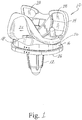
- FIGS. 1 and 2 a typical orthopaedic prosthesis 10 for a total knee replacement is shown in FIGS. 1 and 2 .
- the illustrated prosthesis includes a tibial component 12 or tibial tray to be coupled to the patient's proximal tibia, a femoral component 14 to be coupled to the patient's distal femur, and a bearing component (or tibial insert) 16 positioned between the tibial tray and the femoral component.
- articular surfaces 18, 20 on the femoral component bear and articulate against articular surfaces 22, 24 on the proximal surface of the tibial insert 16 as the knee is moved through flexion and extension.
- a groove on the femoral component 14 provides a third articular surface 26 that articulates against a bearing surface on a patellar implant component (not shown) as the knee is flexed and extended.
- Other surfaces 26, 28 of the implants 12, 14 face the bone when implanted, and may have cement pockets or textured surfaces to encourage bone ingrowth.
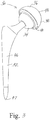
- FIGS. 3-5 A typical orthopaedic prosthesis 30 for hip replacement is shown in FIGS. 3-5 .
- the hip prosthesis 30 includes a metal stem 32 and metal femoral head 34 and an acetabular implant assembly 36 including an acetabular cup 38 and a bearing component (acetabular liner) 40 fixed to the acetabular cup 38 and receiving the femoral head 34.
- acetabular liner bearing component
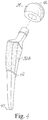
- the stem 32A has some differences compares to the stem 32 of FIG. 3 .
- the femoral implant is modular, comprising an assembly of a stem 32 or 32A component with a femoral head component 34.
- the head component 34 defines a curved articular surface 42 that is received within and articulates against a concave articular surface 44 of the acetabular liner 40.
- the majority of the length of the stem 32 defines a bone-facing surface 46 extending proximally from the distal end 47 bears against and faces the bone (proximal femur).
- the exterior surface of the cup 38 also defines a bone-facing surface 48.
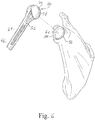
- FIG. 6 A typical orthopaedic prosthesis 50 for shoulder replacement is illustrated in FIG. 6 .
- Common glenoid components 56 include a metal portions and a bearing 58 fixed to the metal portion and receiving or articulating against the humeral head 54.
- the head component 54 defines a convex curved articular surface 60 that is received within and articulates against a concave curved articular surface 62 of the bearing 58.
- the majority of the length of the stem 52 defines a bone-facing surface 64 extending proximally from the distal end 66 and bears against and faces the bone (proximal humerus).
- the exterior surface of the glenoid component also defines a bone-facing surface.
- FIG. 6 illustrates the shoulder prosthesis 50 implanted in the proximal humerus and glenoid.
- the tibial tray 12, distal femoral component 14, femoral stem 32, femoral head 34, acetabular cup 38, humeral stem 52, humeral head 54 and part of the glenoid component 56 are typically made of metal, such as a cobalt chrome alloy or a titanium alloy (such as titanium alloy Ti-6Al-4V, for example).
- the bearing component tibial insert 16, acetabular liner 40 or glenoid bearing 58
- the entire tibial component and entire glenoid component may comprise a polymer.
- the polymer used for the bearing components 16, 40, 58 may be ultrahigh molecular weight polyethylene (UHMWPE).
- UHMWPE ultrahigh molecular weight polyethylene
- the UHMWPE may comprise a cross-linked material, for example.
- Techniques for crosslinking, quenching, or otherwise preparing UHMWPE are described in numerous issued U.S. patents, examples of which include: U.S. Pat. No. 5,728,748 (and its counterparts) issued to Sun, et al.; U.S. Pat. No. 5,879,400 issued to Merrill et al.; U.S. Pat. No. 6,017,975 issued to Saum , et al.; U.S. Pat. No. 6,242,507 issued to Saum et al. ; U.S. Pat. No.
- UHMWPE of the bearing material may be treated to stabilize any free radicals present therein, such as through the addition of an antioxidant such as vitamin E. Techniques for stabilizing UHMWPE with antioxidants are disclosed, for example, in U.S. Pat. Pub. No. 20070293647A1 (Ser. No.
- an articulation surface 18, 20, 26, 42, 60 of one implant component 14, 34, 54 (usually metal or ceramic) bears and articulates against an articular surface 22, 24, 44, 62 of a bearing component 16, 40, 56.
- an articulation surface 18, 20, 26, 42, 60 of one implant component 14, 34, 54 usually metal or ceramic
- the repeated articulation of these components against one another can lead to wear of the bearing component16, 40, 56.
- Excessive wear of the bearing component can lead to issues requiring that the prosthetic joint be removed and replaced with another prosthetic implant in a revision procedure.
- the present invention addresses the goal of improving wear performance of orthopaedic implant prostheses in a cost effective manner.
- the present invention addresses this goal by providing a method of treating the articulation surface of an orthopaedic implant comprising polishing the articulation surface of the orthopaedic implant, blasting the polished surface of the implant followed by polishing the blasted surface.
- the step of polishing the articulation surface comprises drag finishing the articulation surface through an abrasive media.
- the step of polishing the blasted surface may comprise drag finishing the blasted surface through an abrasive media.
- the blasting step is performed with a blasting media.
- the blasting step comprises wet blasting.
- the wet blasting step may be performed with a spherical bead media having a size in the range of 125-180um (B100) or 0-125um (B125), a media concentration in the range of 15-25 % by volume, and with a pressure of 30-40 psi.
- the blasting step increases the roughness of the surface of the metal orthopaedic implant.
- the polishing step before blasting is longer than the polishing step after blasting.
- the articulation surface of the orthopaedic implant component has a negative surface skew (R sk , S sk ) after the second polishing step.
- the first polishing step comprises drag finishing the articulation surface through an abrasive media for a first period of time and the step of polishing the blasted surface comprises drag finishing the blasted surface through an abrasive media for a second period of time.
- the first period of time may be a maximum of 40 minutes and the second period of time may be a maximum of 20 minutes. The maximum time periods may be higher for different starting conditions of material and types of material or alloy used.
- the abrasive media used for the first drag finishing step may comprise plastic ceramic composite
- the abrasive media used for the second drag finishing step may comprise nutshell or corncob bonded with a ceramic polishing media.
- the blasting step may create a surface having a surface roughness (R a / S a ) and skew (R sk / S sk ) defined by a plurality of peaks and valleys and the second polishing step reduces roughness (R a /S a ) and increases the negative skew R sk / S sk of the surface.
- the surface skew R sk / S sk may be from -1 to -3, for example, after the second drag finishing step.
- the average surface roughness after the second polishing step may be less than 0.1 microns. Surface characteristics (roughness and skew) may be measured by white light interferometry.
- the articulation surface of the orthopaedic implant may comprise a metal, such as a standard cobalt-chrome alloy or a titanium alloy.
- the orthopaedic implant may comprise a distal femoral component or a tibial tray of a knee implant, a femoral head of a hip implant, or a humeral head or glenoid component of a shoulder implant.
- Terms representing anatomical references such as anterior, posterior, medial, lateral, proximal, distal, superior, inferior, etcetera, may be used throughout this disclosure in reference to both the orthopaedic implants described herein and a patient's natural anatomy. Such terms have well-understood meanings in both the study of anatomy and the field of orthopaedics. Use of such anatomical reference terms in the specification and claims is intended to be consistent with their well-understood meanings unless noted otherwise.
- the starting point is a standard orthopaedic implant component that has an articulating surface, such as a distal femoral component 14, a femoral head 34 or a humeral head 54, for example.
- the implant may be made of a standard metal, such as a standard CoCrMo alloy or titanium alloy used in orthopaedic implants (although the invention is not limited to any particular alloy unless expressly called for in the claims). It should be understood that these implant components are identified as examples, only; the invention is not limited to these components unless expressly called for in the claims. It is also expected that the principles of the present invention could be applied to ceramic orthopaedic implant components, such as ceramic femoral heads, for example.
- the process of the present invention involves polishing the articulation surface of the implant component, blasting the polished surface and then polishing the blasted surface.
- polishing refers to any standard abrasive manufacturing process that removes material from the surface being polished to reduce the roughness of the surface being polished.
- Standard polishing processes include, for example, vibratory finishing in an abrasive media and tumbling in an abrasive media.
- drag finishing the articulation surface with an abrasive media has proven to be an effective means of polishing the articulation surface.
- blasting refers to a surface treatment that deforms the surface rather than removes material from the surface.
- blasting refers to propelling a media under pressure to at the surface to work the surface.
- blasting the polished articulation surface creates valleys and peaks in the surface through plastic deformation. The peaks are removed in the final polishing step through abrasion to yield a surface with an acceptable surface roughness and a negative skew.
- the implant component may first be mounted on a fixture and placed into a vessel containing an abrasive drag finishing media.
- a plastic abrasive media such as Rosler RKH 4 (polyester resin / ceramic media composite) may be used.
- the mounted implant component is submerged and then moved through the abrasive media in a planetary motion.
- the implant component may be revolved around an axis as the fixture itself is revolved to move the implant component through the media (which may itself be in a revolving vessel). This step will polish the implant component before it is further textured in a wet blasting process.
- the implant component may have an average surface roughness R a /S a of 0.03 ⁇ m after being dragged through the composite media for up to 40 minutes.
- the length of time of the first polishing step may vary depending on the starting conditions of the material and the type of material or alloy used.
- the implant component may again be held by a fixture and then blasted to further roughen the desired surface.
- a wet blasting process may be used, with a pressurized blasting media slurry (for example, Zirblast B100 or Microblast B125 size zirconia media in water 15-25% by volume at a pressure of 30 or 40 psi) applied to the desired surface for a controlled time (for example, 1 minute).
- a pressurized blasting media slurry for example, Zirblast B100 or Microblast B125 size zirconia media in water 15-25% by volume at a pressure of 30 or 40 psi
- This step will further roughen the articulating surface of the implant component by creation of a plurality of peaks and valleys.
- the surface roughness of the implant component after blasting can be characterized as comprising a plurality of peaks and valleys, creating a surface roughness that has an R a , for example, of 0.3 ⁇ m and an R sk of 0 to -1.
- the blasting step may be followed by another drag finishing or polishing step.
- the implant component held by a suitable fixture, may be immersed in another abrasive drag media (such as Rosler Supervelat corncob polishing media, a corncob based media comprising corncob bonded with a ceramic polishing media, www.rosler.us ; Rösler heatntechnik GmbH) and dragged through the media for a period of time and at a speed that will remove or substantially remove the peaks.
- a processing step can be expected to reduce the average roughness R a / S a and create a more negative surface skew R sk / S sk .
- the surfaces of the implant component that are exposed to the abrasive polishing media and blasting media may be controlled so that only the articulating surfaces (such as surfaces 18, 20 of femoral component 14, surface 42 of head 34 or surface 60 of head 54) are exposed. Because it is frequently desirable that the bone-facing surfaces have different surface characteristics, surfaces 26, 28, 46, 48, 64 may be protected from exposure to the media if desired, through masking or by the structure of the fixture holding the components.
- the drag finishing and blasting steps may be performed using commercially available equipment.
- suitable equipment for the drag finishing steps is available from Rösler Metal Finishing ( www.rosler.us ; Rösler bruisentechnik GmbH). This equipment allows for multiple implant components to be mounted on individual spindles, which are in turn mounted on a carousel so that the spindles and carousel may be rotated to move the components through a bowl of abrasive material (the bowl may also be rotated).
- Suitable equipment for the blasting step is available from Rösler Metal Finishing ( www.rosler.us ; Rösler sacrificentechnik GmbH) such as the RWB 48 abrasive wet blasting cabinet..
- the abrasive media used in the process may be standard grinding or polishing media used in the manufacture of medical devices, selected according to the stage of the process.
- the abrasive media can comprise commercially available nutshell or corncob based particles and composites of such particles with other materials such as ceramics.
- "Nutshell or corncob based polishing media” is intended to include commercially available media where nutshell or corncob is bonded with another material such as ceramic.
- "abrasive media” is intended to encompass these media, as well as other standard materials used in conventional polishing processes.
- the polishing step can be a wet or dry step.
- the particular characteristics of the abrasive media used can be selected to produce the desired surface finish properties. Other parameters in the polishing steps (such as speed of rotation of the elements that rotate and drag time) can be adjusted to produce the desired surface finish properties.
- the blast media used in the process may be standard blast media.
- a slurry of zirconia based ceramic beads (“Zirblast”, Saint Gomain, Worcester, MA) in water can be used.
- blast media is intended to encompass ceramic, glass and metal beads, as well as other standard materials used in conventional blast processes.
- the blast process can be a wet or dry process. The particular characteristics of the blast media and the parameters of the blast process (such as pressure and time) can be adjusted to produce the desired surface finish properties.
- sample CoCrMo disks were prepared as set forth in the following table (all of the samples were cast CoCrMo disks, ASTM F75, heat treated [HIP and Homogenized]): Sample group Surface Finish Description Process Parameters 1 Highly Polished Manually polished to a mirror finish 2 Blasted + 2 Stage Polish Plastic based Media Drag for ⁇ 40 minutes (speed: outer carousel at 32 rpm, inner spindle at 20 rpm) Wet blast Zirblast B100 (125-180 ⁇ m) media size at 40 psi for 3 minutes Nutshell based media Drag for 10 minutes (speed: outer carousel at 32 rpm, inner spindle at 20 rpm) 3 Blasted + 2 Stage Polish Plastic based Media Drag for ⁇ 30 minutes (speed: outer carousel at 32 rpm, inner spindle at 20 rpm) Wet blast B125 (0-125 ⁇ m)_ media size at 30 psi for 1 minute Nut
- the plastic-based abrasive media used in the first polishing step in samples 2-4 above was Rosler RKH 4 (polyester resin / ceramic media composite). This same material was used in the plastic media drag steps for samples 5 and 6.
- the nutshell based media used in samples 2, 3 and 6 was Rosler Polishing Grain SVK-747.
- FIG. 7 illustrates the process steps for sample 3.
- the pin-on-disk test was performed using bovine serum (64.8 mg/mL total protein concentration; HyClone Laboratories Inc., Logan, UT) at 37 ⁇ 2°C supplemented with sodium azide and EDTA. Pins were cleaned, weighed and gravimetric wear rates determined six times throughout the course of the test using linear regression in accordance with ISO 14242-2:2000(E) with soak compensation. Wettability (contact angle) was measured using a Kruss drop shape analysis system (DSA 10), and 10 ⁇ l water droplets. The metal components were articulated against parts comprising the DePuy Synthes Joint Reconstruction commercial XLK UHMWPE. This UHMWPE material is made from a GUR 1020 resin irradiated to 50kGy and remelted.
- Sample groups 2 and 3 had S a values within the 0.1 micron specification called out in ISO 21534.
- the S sk values were negative after the final surface finishing step. These samples also exhibited lower water droplet contact angles and wear rates compared to the highly polished control sample 1. These negative skew values indicate that the surface contained pockets that are believed to capture lubricant at the bearing surfaces to improve hydrodynamic lubrication. These pockets can also be expected to entrap potentially harmful wear particulates. It is also expected that these samples will exhibit faster start-up lubrication in vivo.
- a tibial tray 12, femoral component 14, femoral head 34, or humeral head 54 can be finished using the process of the present invention, and it is anticipated that these implant components will exhibit improved wear performance against the articular surfaces of their associated bearings 16, 40, 58.
- the process of the present invention is expected to improve the wear performance of orthopaedic prostheses in a cost effective manner.
Landscapes
- Health & Medical Sciences (AREA)
- Engineering & Computer Science (AREA)
- Orthopedic Medicine & Surgery (AREA)
- Transplantation (AREA)
- Vascular Medicine (AREA)
- Oral & Maxillofacial Surgery (AREA)
- Biomedical Technology (AREA)
- Heart & Thoracic Surgery (AREA)
- Cardiology (AREA)
- Life Sciences & Earth Sciences (AREA)
- Animal Behavior & Ethology (AREA)
- General Health & Medical Sciences (AREA)
- Public Health (AREA)
- Veterinary Medicine (AREA)
- Mechanical Engineering (AREA)
- Physical Education & Sports Medicine (AREA)
- Prostheses (AREA)
Abstract
Description
- The present disclosure relates generally to orthopaedic prostheses, and more particularly to a method of preparing the articulating surface of one of the components of an orthopaedic implant system.
- Movement of the joints of human musculoskeletal system involves movements of adjacent bones through various ranges of motion. For example, movement of the human knee involves movements of the femur, tibia and the patella. Specifically, during flexion and extension, the distal end of the femur and the proximal end of the tibia articulate relative to one another through a series of complex movements as the patella articulates with the femur. Similarly, movement of the human hip involves movements of the femur with respect to the acetabulum, and movement of the shoulder involves movement of the humerus with respect to the glenoid. Damage (e.g., trauma) or disease can deteriorate the bones, articular cartilage, and ligaments of the bones associated with these joints, which can ultimately affect the ability of the natural joint to function properly. As a result, orthopaedic prostheses have been developed and implanted into surgically prepared ends of the bones of the joints to provide greater mobility for the patient.
- For example, a typical
orthopaedic prosthesis 10 for a total knee replacement is shown inFIGS. 1 and2 . The illustrated prosthesis includes atibial component 12 or tibial tray to be coupled to the patient's proximal tibia, afemoral component 14 to be coupled to the patient's distal femur, and a bearing component (or tibial insert) 16 positioned between the tibial tray and the femoral component. - Once implanted,
articular surfaces articular surfaces tibial insert 16 as the knee is moved through flexion and extension. A groove on thefemoral component 14 provides a thirdarticular surface 26 that articulates against a bearing surface on a patellar implant component (not shown) as the knee is flexed and extended.Other surfaces implants - A typical
orthopaedic prosthesis 30 for hip replacement is shown inFIGS. 3-5 . Thehip prosthesis 30 includes ametal stem 32 and metalfemoral head 34 and anacetabular implant assembly 36 including anacetabular cup 38 and a bearing component (acetabular liner) 40 fixed to theacetabular cup 38 and receiving thefemoral head 34. - In the embodiment illustrated in
FIG. 4 , thestem 32A has some differences compares to thestem 32 ofFIG. 3 . In both, the femoral implant is modular, comprising an assembly of astem femoral head component 34. Thehead component 34 defines a curvedarticular surface 42 that is received within and articulates against a concavearticular surface 44 of theacetabular liner 40. The majority of the length of thestem 32 defines a bone-facingsurface 46 extending proximally from thedistal end 47 bears against and faces the bone (proximal femur). The exterior surface of thecup 38 also defines a bone-facingsurface 48. - A typical
orthopaedic prosthesis 50 for shoulder replacement is illustrated inFIG. 6 . includes ametal stem 52 and metalhumeral head 54 and a glenoid component 56. Common glenoid components 56 include a metal portions and abearing 58 fixed to the metal portion and receiving or articulating against thehumeral head 54. Thehead component 54 defines a convex curvedarticular surface 60 that is received within and articulates against a concave curvedarticular surface 62 of thebearing 58. The majority of the length of thestem 52 defines a bone-facingsurface 64 extending proximally from thedistal end 66 and bears against and faces the bone (proximal humerus). The exterior surface of the glenoid component also defines a bone-facing surface.FIG. 6 illustrates theshoulder prosthesis 50 implanted in the proximal humerus and glenoid. - In such typical orthopaedic prostheses, the
tibial tray 12, distalfemoral component 14,femoral stem 32,femoral head 34,acetabular cup 38,humeral stem 52,humeral head 54 and part of the glenoid component 56 are typically made of metal, such as a cobalt chrome alloy or a titanium alloy (such as titanium alloy Ti-6Al-4V, for example). The bearing component (tibial insert 16,acetabular liner 40 or glenoid bearing 58) is typically made of a polymer, or in the case of hip prostheses, may comprise a metal or ceramic liner. In some cases, the entire tibial component and entire glenoid component may comprise a polymer. - The polymer used for the
bearing components U.S. Pat. No. 5,728,748 (and its counterparts) issued to Sun, et al.;U.S. Pat. No. 5,879,400 issued to Merrill et al.;U.S. Pat. No. 6,017,975 issued to Saum , et al.;U.S. Pat. No. 6,242,507 issued to Saum et al. ;U.S. Pat. No. 6,316,158 issued to Saum et al.;U.S. Pat. No. 6,228,900 issued to Shen et al.;U.S. Pat. No. 6,245,276 issued to McNulty et al.; andU.S. Pat. No. 6,281,264 issued to Salovey et al. The disclosure of each of these U.S. patents is incorporated by reference herein in their entireties. The UHMWPE of the bearing material may be treated to stabilize any free radicals present therein, such as through the addition of an antioxidant such as vitamin E. Techniques for stabilizing UHMWPE with antioxidants are disclosed, for example, inU.S. Pat. Pub. No. 20070293647A1 (Ser. No.11/805,867 U.S. Pat. Pub. No. 20030212161A1 (Ser. No.10/258,762 - Each of these implant systems share some common characteristics: an
articulation surface implant component articular surface bearing component - To address wear, various solutions have been proposed. For example, attempts have been made to reduce wear by optimizing the polishing of the metal articulating surface(s) to a high gloss. Such polishing processes can however be costly. Some have suggested providing a textured surface through etching or anodizing to contain a biological fluid to improve lubrication. See, for example,
WO2015/034471A1 . - The present invention addresses the goal of improving wear performance of orthopaedic implant prostheses in a cost effective manner.
- According to one aspect, the present invention addresses this goal by providing a method of treating the articulation surface of an orthopaedic implant comprising polishing the articulation surface of the orthopaedic implant, blasting the polished surface of the implant followed by polishing the blasted surface.
- In a particular embodiment, the step of polishing the articulation surface comprises drag finishing the articulation surface through an abrasive media. Similarly, the step of polishing the blasted surface may comprise drag finishing the blasted surface through an abrasive media.
- The blasting step is performed with a blasting media. In a particular embodiment, the blasting step comprises wet blasting. The wet blasting step may be performed with a spherical bead media having a size in the range of 125-180um (B100) or 0-125um (B125), a media concentration in the range of 15-25 % by volume, and with a pressure of 30-40 psi. In this embodiment, the blasting step increases the roughness of the surface of the metal orthopaedic implant.
- In a more particular embodiment, the polishing step before blasting is longer than the polishing step after blasting.
- In any of these embodiments, the articulation surface of the orthopaedic implant component has a negative surface skew (Rsk, Ssk) after the second polishing step.
- In another more particular embodiment, the first polishing step comprises drag finishing the articulation surface through an abrasive media for a first period of time and the step of polishing the blasted surface comprises drag finishing the blasted surface through an abrasive media for a second period of time. In these embodiments, the first period of time may be a maximum of 40 minutes and the second period of time may be a maximum of 20 minutes. The maximum time periods may be higher for different starting conditions of material and types of material or alloy used.
- In any of these embodiments, the abrasive media used for the first drag finishing step may comprise plastic ceramic composite, and the abrasive media used for the second drag finishing step may comprise nutshell or corncob bonded with a ceramic polishing media.
- In any of these embodiments, the blasting step may create a surface having a surface roughness (Ra / Sa) and skew (Rsk / Ssk) defined by a plurality of peaks and valleys and the second polishing step reduces roughness (Ra/Sa) and increases the negative skew Rsk / Ssk of the surface. The surface skew Rsk / Ssk may be from -1 to -3, for example, after the second drag finishing step. The average surface roughness after the second polishing step may be less than 0.1 microns. Surface characteristics (roughness and skew) may be measured by white light interferometry.
- In any of these embodiments, the articulation surface of the orthopaedic implant may comprise a metal, such as a standard cobalt-chrome alloy or a titanium alloy.
- In any of these embodiments, the orthopaedic implant may comprise a distal femoral component or a tibial tray of a knee implant, a femoral head of a hip implant, or a humeral head or glenoid component of a shoulder implant.
- The background and detailed description particularly refer to the following figures, in which:
-
FIG. 1 is a perspective view of an example of an orthopaedic knee prosthesis system; -
FIG. 2 is an exploded view of the knee prosthesis system ofFIG. 1 ; -
FIG. 3 is a perspective view of an example of an orthopaedic hip prosthesis system; -
FIG. 4 is an exploded perspective view of a femoral stem and femoral head of an example of an orthopaedic hip prosthesis system; -
FIG. 5 is an exploded view of an example of an acetabular cup and liner for use in an orthopaedic hip prosthesis system; -
FIG. 6 is perspective view of an example of an orthopaedic shoulder prosthesis system, shown implanted on a humerus and shoulder; and -
FIG. 7 is a flow chart of process steps for finishing the articular surface of one or more of the metal components of an orthopaedic prosthesis system, such as the systems shown inFIGS. 1-6 . - While the concepts of the present disclosure are susceptible to various modifications and alternative forms, specific exemplary embodiments thereof have been shown by way of example in the drawings and will herein be described in detail. It should be understood, however, that there is no intent to limit the disclosure to the particular forms disclosed, but on the contrary, the intention is to cover all modifications, equivalents, and alternatives falling within the spirit and scope of the invention as defined by the appended claims.
- Terms representing anatomical references, such as anterior, posterior, medial, lateral, proximal, distal, superior, inferior, etcetera, may be used throughout this disclosure in reference to both the orthopaedic implants described herein and a patient's natural anatomy. Such terms have well-understood meanings in both the study of anatomy and the field of orthopaedics. Use of such anatomical reference terms in the specification and claims is intended to be consistent with their well-understood meanings unless noted otherwise.
- Terms related to the characterization of surface roughness may be used throughout their disclosure. For example, average surface roughness Ra, Sa and surface skew Rsk, Ssk are used. Use of these terms is intended to be consistent with their well-understood meanings unless noted otherwise. In addition, standard methods of measuring and/or characterizing surface textures, and standard equipment used in measuring and/or characterizing surface textures are intended to be usable with respect to the present invention unless expressly excluded.
- Although the results below are reported as three-dimensional results (Sa and Ssk), it should be understood that the results should be comparable for 2-dimensional measurement (Ra and Rsk). References to specific values of surface roughness and skew should be understood to refer to either Sa and Ra and Ssk and Rsk unless otherwise specifically called out.
- In the process of the present invention, the starting point is a standard orthopaedic implant component that has an articulating surface, such as a distal
femoral component 14, afemoral head 34 or ahumeral head 54, for example. The implant may be made of a standard metal, such as a standard CoCrMo alloy or titanium alloy used in orthopaedic implants (although the invention is not limited to any particular alloy unless expressly called for in the claims). It should be understood that these implant components are identified as examples, only; the invention is not limited to these components unless expressly called for in the claims. It is also expected that the principles of the present invention could be applied to ceramic orthopaedic implant components, such as ceramic femoral heads, for example. - In general, the process of the present invention involves polishing the articulation surface of the implant component, blasting the polished surface and then polishing the blasted surface.
- As used herein, "polishing" refers to any standard abrasive manufacturing process that removes material from the surface being polished to reduce the roughness of the surface being polished. Standard polishing processes include, for example, vibratory finishing in an abrasive media and tumbling in an abrasive media. In the case of the examples below, drag finishing the articulation surface with an abrasive media has proven to be an effective means of polishing the articulation surface.
- In contrast, "blasting" refers to a surface treatment that deforms the surface rather than removes material from the surface. Generally, blasting refers to propelling a media under pressure to at the surface to work the surface. In the case of the examples below, blasting the polished articulation surface creates valleys and peaks in the surface through plastic deformation. The peaks are removed in the final polishing step through abrasion to yield a surface with an acceptable surface roughness and a negative skew.
- The implant component may first be mounted on a fixture and placed into a vessel containing an abrasive drag finishing media. For example, a plastic abrasive media such as Rosler RKH 4 (polyester resin / ceramic media composite) may be used. The mounted implant component is submerged and then moved through the abrasive media in a planetary motion. For example, the implant component may be revolved around an axis as the fixture itself is revolved to move the implant component through the media (which may itself be in a revolving vessel). This step will polish the implant component before it is further textured in a wet blasting process. For example, the implant component may have an average surface roughness Ra /Sa of 0.03 µm after being dragged through the composite media for up to 40 minutes. The length of time of the first polishing step may vary depending on the starting conditions of the material and the type of material or alloy used.
- After this first polishing step, the implant component may again be held by a fixture and then blasted to further roughen the desired surface. For example, a wet blasting process may be used, with a pressurized blasting media slurry (for example, Zirblast B100 or Microblast B125 size zirconia media in water 15-25% by volume at a pressure of 30 or 40 psi) applied to the desired surface for a controlled time (for example, 1 minute). This step will further roughen the articulating surface of the implant component by creation of a plurality of peaks and valleys.
- The surface roughness of the implant component after blasting can be characterized as comprising a plurality of peaks and valleys, creating a surface roughness that has an Ra, for example, of 0.3µm and an Rsk of 0 to -1.
- To reduce or eliminate the peaks generated by the blasting step, while retaining the valleys created, the blasting step may be followed by another drag finishing or polishing step. For example, the implant component, held by a suitable fixture, may be immersed in another abrasive drag media (such as Rosler Supervelat corncob polishing media, a corncob based media comprising corncob bonded with a ceramic polishing media, www.rosler.us; Rösler Oberflächentechnik GmbH) and dragged through the media for a period of time and at a speed that will remove or substantially remove the peaks. Such a processing step can be expected to reduce the average roughness Ra / Sa and create a more negative surface skew Rsk / Ssk.
- Throughout the polishing and blasting steps, the surfaces of the implant component that are exposed to the abrasive polishing media and blasting media may be controlled so that only the articulating surfaces (such as
surfaces femoral component 14,surface 42 ofhead 34 orsurface 60 of head 54) are exposed. Because it is frequently desirable that the bone-facing surfaces have different surface characteristics, surfaces 26, 28, 46, 48, 64 may be protected from exposure to the media if desired, through masking or by the structure of the fixture holding the components. - The drag finishing and blasting steps may be performed using commercially available equipment. For example, suitable equipment for the drag finishing steps is available from Rösler Metal Finishing (www.rosler.us; Rösler Oberflächentechnik GmbH). This equipment allows for multiple implant components to be mounted on individual spindles, which are in turn mounted on a carousel so that the spindles and carousel may be rotated to move the components through a bowl of abrasive material (the bowl may also be rotated). Suitable equipment for the blasting step is available from Rösler Metal Finishing (www.rosler.us; Rösler Oberflächentechnik GmbH) such as the
RWB 48 abrasive wet blasting cabinet.. - The abrasive media used in the process may be standard grinding or polishing media used in the manufacture of medical devices, selected according to the stage of the process. For example, the abrasive media can comprise commercially available nutshell or corncob based particles and composites of such particles with other materials such as ceramics. "Nutshell or corncob based polishing media" is intended to include commercially available media where nutshell or corncob is bonded with another material such as ceramic. As used herein, "abrasive media" is intended to encompass these media, as well as other standard materials used in conventional polishing processes. The polishing step can be a wet or dry step. The particular characteristics of the abrasive media used can be selected to produce the desired surface finish properties. Other parameters in the polishing steps (such as speed of rotation of the elements that rotate and drag time) can be adjusted to produce the desired surface finish properties.
- Similarly, the blast media used in the process may be standard blast media. For example, a slurry of zirconia based ceramic beads ("Zirblast", Saint Gomain, Worcester, MA) in water can be used. As used herein, "blast media" is intended to encompass ceramic, glass and metal beads, as well as other standard materials used in conventional blast processes. The blast process can be a wet or dry process. The particular characteristics of the blast media and the parameters of the blast process (such as pressure and time) can be adjusted to produce the desired surface finish properties.
- To compare the process of the present invention to the prior art polishing process, sample CoCrMo disks were prepared as set forth in the following table (all of the samples were cast CoCrMo disks, ASTM F75, heat treated [HIP and Homogenized]):
Sample group Surface Finish Description Process Parameters 1 Highly Polished Manually polished to a mirror finish 2 Blasted + 2 Stage Polish Plastic based Media Drag for < 40 minutes (speed: outer carousel at 32 rpm, inner spindle at 20 rpm) Wet blast Zirblast B100 (125-180µm) media size at 40 psi for 3 minutes Nutshell based media Drag for 10 minutes (speed: outer carousel at 32 rpm, inner spindle at 20 rpm) 3 Blasted + 2 Stage Polish Plastic based Media Drag for < 30 minutes (speed: outer carousel at 32 rpm, inner spindle at 20 rpm) Wet blast B125 (0-125µm)_ media size at 30 psi for 1 minute Nutshell based media Drag for 4 minutes (speed: outer carousel at 32 rpm, inner spindle at 20 rpm) 4 2 Stage - Polish and Blast Plastic based media Drag for 30 minutes (speed: outer carousel at 32 rpm, inner spindle at 20 rpm) Wet blast B125 (0-125µm)_ media size at 40 psi for 1 minute -- 5 2 Stage Drag Ceramic based media Drag for 100 minutes (speed: outer carousel at 32 rpm, inner spindle at 20 rpm) Plastic Media Drag for 64 minutes (speed: outer carousel at 32 rpm, inner spindle at 20 rpm) -- 6 3 Stage Polish Ceramic based media Drag for 100 minutes (speed: outer carousel at 32 rpm, inner spindle at 20 rpm) Plastic Media Drag for 64 minutes (speed: outer carousel at 32 rpm, inner spindle at 20 rpm) Nutshell based media Drag for 44 minutes (speed: outer carousel at 32 rpm, inner spindle at 20 rpm) - The plastic-based abrasive media used in the first polishing step in samples 2-4 above was Rosler RKH 4 (polyester resin / ceramic media composite). This same material was used in the plastic media drag steps for samples 5 and 6. The nutshell based media used in samples 2, 3 and 6 was Rosler Polishing Grain SVK-747.
-
FIG. 7 illustrates the process steps for sample 3. - As set forth below, surfaces of the samples identified above were characterized to determine Sa and Ssk, and a pin on disk wear test was also performed. The surface characterization was done using white light interferometry (Zygo NewView 5000, Middlefield, CT). Pin-on-disk wear testing was performed using an OrthoPOD pin-on-disk tribometer (AMTI, Watertown, MA) under variable load and articulation representative of a Paul curve (Paul, Proc. Inst. Mech. Eng. 181, 8-15, 1967) with a peak load of 330N for 1.98MCyc. The pin-on-disk test was performed using bovine serum (64.8 mg/mL total protein concentration; HyClone Laboratories Inc., Logan, UT) at 37±2°C supplemented with sodium azide and EDTA. Pins were cleaned, weighed and gravimetric wear rates determined six times throughout the course of the test using linear regression in accordance with ISO 14242-2:2000(E) with soak compensation. Wettability (contact angle) was measured using a Kruss drop shape analysis system (DSA 10), and 10µl water droplets. The metal components were articulated against parts comprising the DePuy Synthes Joint Reconstruction commercial XLK UHMWPE. This UHMWPE material is made from a GUR 1020 resin irradiated to 50kGy and remelted.
Sample group Average Surface roughness Sa before Pin-on-disk testing (µm) Average Surface roughness Sa After Pin-on-disk testing (µm) Skew Ssk Average Wear Rate mg/Mcyc Average Wettability (contact angle) 1 0.02 0.03 +1.0 (±0.5) 7.2 98 2 0.06 0.07 -2.2 (±0.8) 3.4 68 3 0.04 0.05 -1.2 (±0.4) 3.6 65 4 0.2 0.25 0 (±0.8) 7.0 75 5 0.02 0.035 0 (±0.3) 7.3 70 6 0.02 0.04 +1.0 (±0.5) 7.2 95 - For some samples, surface roughness was also characterized during the process. For example, in Sample group 2, Sa and Ssk were measured after the blasting step as 0.32µm and 0.8, respectively.
- Sample groups 2 and 3 had Sa values within the 0.1 micron specification called out in ISO 21534. For sample groups 2 and 3, the Ssk values were negative after the final surface finishing step. These samples also exhibited lower water droplet contact angles and wear rates compared to the highly polished control sample 1. These negative skew values indicate that the surface contained pockets that are believed to capture lubricant at the bearing surfaces to improve hydrodynamic lubrication. These pockets can also be expected to entrap potentially harmful wear particulates. It is also expected that these samples will exhibit faster start-up lubrication in vivo.
- The above-described processes can be applied to implant components. For example, the articulating surfaces of a
tibial tray 12,femoral component 14,femoral head 34, orhumeral head 54 can be finished using the process of the present invention, and it is anticipated that these implant components will exhibit improved wear performance against the articular surfaces of their associatedbearings - Accordingly, the process of the present invention is expected to improve the wear performance of orthopaedic prostheses in a cost effective manner.
- While the concepts of the present disclosure have been illustrated and described in detail in the drawings and foregoing description, such an illustration and description is to be considered as exemplary and not restrictive in character, it being understood that only the illustrative embodiments have been shown and described and that all changes and modifications that come within the spirit of the disclosure are desired to be protected.
- There are a plurality of advantages of the present disclosure arising from the various features of the apparatus and methods described herein. It will be noted that alternative embodiments of the apparatus and methods of the present disclosure may not include all of the features described yet still benefit from at least some of the advantages of such features. Those of ordinary skill in the art may readily devise their own implementations of an apparatus and method that incorporate one or more of the features of the present disclosure and fall within the spirit and scope of the present disclosure.
Claims (22)
- A method of treating an articulation surface of an orthopaedic implant comprising:polishing the articulation surface of the orthopaedic implant;blasting the polished surface of the orthopaedic implant; andpolishing the blasted surface of the orthopaedic implant.
- The method of claim 1 wherein the step of polishing the articulation surface of the orthopaedic implant comprises drag finishing the articulation surface of the orthopaedic implant with an abrasive media.
- The method of claim 1 wherein the step of polishing the blasted surface of the orthopaedic implant comprises drag finishing the articulation surface of the orthopaedic implant with an abrasive media.
- The method of claim 1 wherein blasting comprises wet blasting.
- The method of claim 4 wherein blasting comprises wet blasting with a ceramic bead media having a size in the range of B100 to B 125 at a pressure of 30-40 psi to increase the roughness of the surface of the metal orthopaedic implant.
- The method of claim 1 wherein the polishing step before blasting is longer than the polishing step after blasting.
- The method of claim 1 wherein the articulation surface of the orthopaedic implant has a negative surface skew (Ssk) after the second polishing step.
- The method of claim 1 wherein:the step of polishing the articulation surface of the orthopaedic implant comprises drag finishing the articulation surface of the orthopaedic implant with an abrasive media for a first period of time; andthe step of polishing the blasted surface of the orthopaedic implant comprises drag finishing the blasted surface of the orthopaedic implant with an abrasive media for a second period of time.
- The method of claim 8 wherein the first period of time maximum of 40 minutes.
- The method of claim 8 wherein the second period of time is a maximum of 20 minutes.
- The method of claim 8 wherein the abrasive media used in the first drag finishing step comprises a plastic ceramic composite.
- The method of claim 8 wherein the abrasive media used in the second drag finishing step comprises nutshell or corncob based polishing media.
- The method of claim 8 wherein the blasting step creates a surface having a surface skew defined by a plurality of peaks and valleys and the second drag finishing step creates a surface having a negative skew.
- The method of claim 8 wherein the articulation surface of the orthopaedic implant has a surface skew of from -1 to -3 after the second drag finishing step.
- The method of claim 8 wherein the articulation surface of the orthopaedic implant has an average surface roughness of less than 0.1 microns after the second drag finishing step.
- The method of claim 15 wherein the articulation surface of the orthopaedic implant has a surface skew of from -1 to -3 after the second drag finishing step.
- The method of claim 8 wherein the articulation surface of the orthopaedic implant comprises metal.
- The method of claim 17 wherein the articulation surface of the orthopaedic implant comprises a metal selected from a group including a cobalt-chrome alloy and a titanium alloy.
- The method of claim 8 wherein the orthopaedic implant is selected from a group including:a distal femoral component of an orthopaedic knee implant;a tibial tray of an orthopaedic knee implant;a femoral head of an orthopaedic hip implant;a humeral head of an orthopaedic shoulder implant; anda glenoid component of an orthopaedic shoulder implant.
- The method of claim 19 wherein the articulation surface of the orthopaedic implant:has an average surface roughness (Sa) of less than 0.1 microns after the second drag finishing step as measured by white light interferometry;has a surface skew (Ssk) of from -1 to -3 after the second drag finishing step as measured by white light interferometry; andcomprises a metal selected from a group including a cobalt-chrome alloy and a titanium alloy.
- The method of claim 20 wherein blasting comprises wet blasting with a ceramic bead media having a size in the range of B100 to B 125 at a pressure of 30-40 psi to increase the roughness of the surface of the metal orthopaedic implant.
- The method of claim 21 wherein:the first period of time maximum of 40 minutes;the second period of time is a maximum of 20 minutes;the abrasive media used in the first drag finishing step comprises a plastic composite; andthe abrasive media used in the second drag finishing step comprises nutshell or corncob based polishing media.
Applications Claiming Priority (1)
| Application Number | Priority Date | Filing Date | Title |
|---|---|---|---|
| US15/278,498 US10070959B2 (en) | 2016-09-28 | 2016-09-28 | Method of texturing prosthetic implants |
Publications (2)
| Publication Number | Publication Date |
|---|---|
| EP3300698A1 true EP3300698A1 (en) | 2018-04-04 |
| EP3300698B1 EP3300698B1 (en) | 2020-11-18 |
Family
ID=59930283
Family Applications (1)
| Application Number | Title | Priority Date | Filing Date |
|---|---|---|---|
| EP17192544.9A Active EP3300698B1 (en) | 2016-09-28 | 2017-09-22 | Method of texturing prosthetic implants |
Country Status (5)
| Country | Link |
|---|---|
| US (1) | US10070959B2 (en) |
| EP (1) | EP3300698B1 (en) |
| JP (1) | JP7066363B2 (en) |
| CN (1) | CN107865713B (en) |
| AU (1) | AU2017235892A1 (en) |
Families Citing this family (5)
| Publication number | Priority date | Publication date | Assignee | Title |
|---|---|---|---|---|
| EP3586522B1 (en) * | 2017-02-23 | 2023-01-18 | Sonova AG | Method of manufacturing a hearing device housing |
| US20230240853A1 (en) * | 2020-04-22 | 2023-08-03 | Kyocera Corporation | Artificial joint shell and method for manufacturing artificial joint shell |
| CN113305740B (en) * | 2021-05-13 | 2023-03-24 | 上海交通大学 | Method for improving surface smoothness of artificial joint casting |
| US20240382312A1 (en) * | 2021-09-17 | 2024-11-21 | Invibio Knees Limited | Moulded article and method of manufacture |
| WO2023208389A1 (en) * | 2022-04-29 | 2023-11-02 | Depuy Ireland Unlimited Company | Bendable titanium-alloy implants |
Citations (12)
| Publication number | Priority date | Publication date | Assignee | Title |
|---|---|---|---|---|
| US5728748A (en) | 1993-06-01 | 1998-03-17 | Howmedica Inc. | Non oxidizing polymeric medical implant |
| US5746272A (en) * | 1996-09-30 | 1998-05-05 | Johnson & Johnson Professional, Inc. | Investment casting |
| US5879400A (en) | 1996-02-13 | 1999-03-09 | Massachusetts Institute Of Technology | Melt-irradiated ultra high molecular weight polyethylene prosthetic devices |
| US6017975A (en) | 1996-10-02 | 2000-01-25 | Saum; Kenneth Ashley | Process for medical implant of cross-linked ultrahigh molecular weight polyethylene having improved balance of wear properties and oxidation resistance |
| US6025536A (en) * | 1997-08-20 | 2000-02-15 | Bristol-Myers Squibb Company | Process of manufacturing a cobalt-chromium orthopaedic implant without covering defects in the surface of the implant |
| US6228900B1 (en) | 1996-07-09 | 2001-05-08 | The Orthopaedic Hospital And University Of Southern California | Crosslinking of polyethylene for low wear using radiation and thermal treatments |
| US6245276B1 (en) | 1999-06-08 | 2001-06-12 | Depuy Orthopaedics, Inc. | Method for molding a cross-linked preform |
| US6281264B1 (en) | 1995-01-20 | 2001-08-28 | The Orthopaedic Hospital | Chemically crosslinked ultrahigh molecular weight polyethylene for artificial human joints |
| US20030212161A1 (en) | 2000-04-27 | 2003-11-13 | Mckellop Harry A | Oxidation-resistant and wear-resistant polyethylenes for human joint replacements and methods for making them |
| WO2012041571A1 (en) * | 2010-09-28 | 2012-04-05 | Ala Ortho S.R.L. | Method for improving the strength characteristics of orthopedic prostheses |
| WO2015034471A1 (en) | 2013-09-03 | 2015-03-12 | Massachusetts Institute Of Technology | Orthopaedic joints providing enhanced lubricity |
| US20150151399A1 (en) * | 2012-04-25 | 2015-06-04 | On-X Life Technologies, Inc. | Mass finishing component enclosure device and system |
Family Cites Families (41)
| Publication number | Priority date | Publication date | Assignee | Title |
|---|---|---|---|---|
| JPS5934252A (en) * | 1982-08-23 | 1984-02-24 | 有限会社友信開発 | Low friction artificial joint |
| JP2543747B2 (en) * | 1988-05-31 | 1996-10-16 | 日本特殊陶業株式会社 | Artificial head |
| US5258098A (en) | 1991-06-17 | 1993-11-02 | Cycam, Inc. | Method of production of a surface adapted to promote adhesion |
| US5211833A (en) * | 1991-07-24 | 1993-05-18 | Queen's University At Kingston | Method for coating implants and surgical devices made of titanium and titanium alloys |
| JPH06313430A (en) * | 1993-03-05 | 1994-11-08 | Nippon Seiko Kk | Wear and abrasion resistance sliding member |
| US5308412A (en) | 1993-03-15 | 1994-05-03 | Zimmer, Inc. | Method of surface hardening cobalt-chromium based alloys for orthopedic implant devices |
| US5681205A (en) * | 1993-08-12 | 1997-10-28 | Church & Dwight Co., Inc. | Method of using abrasive blast media containing corrosion inhibitor |
| JP3590992B2 (en) * | 1994-06-17 | 2004-11-17 | 日本精工株式会社 | Wear-resistant sliding member |
| US5560096B1 (en) * | 1995-01-23 | 1998-03-10 | Smith & Nephew Richards Inc | Method of manufacturing femoral knee implant |
| JP3886170B2 (en) * | 1995-03-02 | 2007-02-28 | 株式会社ジェイテクト | Rolling parts |
| JP3524978B2 (en) * | 1995-03-02 | 2004-05-10 | 光洋精工株式会社 | Rollers for cam followers |
| EP0811789B1 (en) | 1995-11-21 | 2001-08-08 | Koyo Seiko Co., Ltd. | Mechanical part |
| US5906234A (en) * | 1996-10-22 | 1999-05-25 | Johnson & Johnson Professional, Inc. | Investment casting |
| US5746691A (en) | 1997-06-06 | 1998-05-05 | Global Therapeutics, Inc. | Method for polishing surgical stents |
| DE19750121C1 (en) | 1997-11-13 | 1999-04-08 | Eska Implants Gmbh & Co | Sliding surfaces for an artificial joint |
| US8323349B2 (en) | 2004-02-17 | 2012-12-04 | The University Of Notre Dame Du Lac | Textured surfaces for orthopedic implants |
| JP2005249150A (en) | 2004-03-08 | 2005-09-15 | Daido Metal Co Ltd | Sliding member, and its manufacturing method and device |
| EP1674051B1 (en) * | 2004-12-23 | 2007-08-15 | Plus Orthopedics AG | A method of surface finishing a bone implant |
| US7959490B2 (en) | 2005-10-31 | 2011-06-14 | Depuy Products, Inc. | Orthopaedic component manufacturing method and equipment |
| EP1825839B1 (en) * | 2006-02-28 | 2011-09-21 | Ostomycure AS | Implant |
| US7892071B2 (en) * | 2006-09-29 | 2011-02-22 | Depuy Products, Inc. | Orthopaedic component manufacturing method and equipment |
| DE102007013638A1 (en) | 2007-03-19 | 2008-09-25 | Degudent Gmbh | Method of polishing metallic tooth reconstructions |
| DE102007014265B4 (en) | 2007-03-21 | 2009-08-13 | Eska Implants Gmbh & Co.Kg | Joint ball or cap for an artificial hip joint |
| EP2310059B1 (en) * | 2008-05-29 | 2016-11-16 | Numat Biomedical S.L. | Pufa covered implants |
| JP2010169182A (en) | 2009-01-22 | 2010-08-05 | Nsk Ltd | Roller bearing |
| US8580134B2 (en) | 2009-04-15 | 2013-11-12 | DePuy Synthes Products, LLC. | Nanotextured cobalt-chromium alloy articles having high wettability and method of producing same |
| US8209857B2 (en) * | 2009-06-19 | 2012-07-03 | The Regents Of The University Of Michigan | Method of making a thin film device |
| EP2606849A1 (en) * | 2011-12-22 | 2013-06-26 | Dentsply IH AB | Method of blasting metallic implants with titanium oxide |
| EP2836168B1 (en) * | 2012-04-13 | 2016-09-28 | ConforMIS, Inc. | Methods for additive manufacturing of implant components |
| EP2656944B1 (en) * | 2012-04-23 | 2018-03-21 | Biotronik AG | Method for producing an implant |
| CN103371922B (en) * | 2012-04-26 | 2015-07-15 | 北京汇福康医疗技术有限公司 | Method for performing liquid sand blasting treatment on surface of implant material |
| US10806831B2 (en) * | 2012-05-09 | 2020-10-20 | Sintx Technologies, Inc. | Antibacterial biomedical implants and associated materials, apparatus, and methods |
| US9925295B2 (en) * | 2012-05-09 | 2018-03-27 | Amedica Corporation | Ceramic and/or glass materials and related methods |
| WO2014008284A1 (en) | 2012-07-02 | 2014-01-09 | University Of Utah Research Foundation | Prosthetic joint |
| CN104780872B (en) * | 2012-09-21 | 2017-04-05 | 康复米斯公司 | The method and system of the design and manufacture of optimization implant component is manufactured using free entity |
| CN102921037B (en) * | 2012-10-31 | 2014-05-07 | 厦门大学 | Method for preparing multistage micron structure on titanium implant surface |
| US20150198206A1 (en) | 2013-11-13 | 2015-07-16 | Nexteer (Beijing) Technology Co., Ltd. | Torque-transmitting joint and joint components, methods of manufacturing, and methods of inspection |
| AU2015269000A1 (en) * | 2014-06-05 | 2016-12-22 | Ossis Limited | Improvements to implant surfaces |
| WO2016044352A1 (en) * | 2014-09-15 | 2016-03-24 | Conformis, Inc. | 3d printing surgical repair systems |
| CN105666338B (en) * | 2016-02-25 | 2019-04-02 | 苏州市永通不锈钢有限公司 | Stainless steel surface treatment process with precise control of roughness |
| US10959850B2 (en) * | 2016-06-01 | 2021-03-30 | Corentec Co., Ltd. | Implant having porous layer and molding method thereof |
-
2016
- 2016-09-28 US US15/278,498 patent/US10070959B2/en active Active
-
2017
- 2017-09-22 EP EP17192544.9A patent/EP3300698B1/en active Active
- 2017-09-26 AU AU2017235892A patent/AU2017235892A1/en not_active Abandoned
- 2017-09-27 JP JP2017185875A patent/JP7066363B2/en active Active
- 2017-09-28 CN CN201710896476.1A patent/CN107865713B/en active Active
Patent Citations (15)
| Publication number | Priority date | Publication date | Assignee | Title |
|---|---|---|---|---|
| US5728748A (en) | 1993-06-01 | 1998-03-17 | Howmedica Inc. | Non oxidizing polymeric medical implant |
| US6281264B1 (en) | 1995-01-20 | 2001-08-28 | The Orthopaedic Hospital | Chemically crosslinked ultrahigh molecular weight polyethylene for artificial human joints |
| US5879400A (en) | 1996-02-13 | 1999-03-09 | Massachusetts Institute Of Technology | Melt-irradiated ultra high molecular weight polyethylene prosthetic devices |
| US6228900B1 (en) | 1996-07-09 | 2001-05-08 | The Orthopaedic Hospital And University Of Southern California | Crosslinking of polyethylene for low wear using radiation and thermal treatments |
| US5746272A (en) * | 1996-09-30 | 1998-05-05 | Johnson & Johnson Professional, Inc. | Investment casting |
| US6242507B1 (en) | 1996-10-02 | 2001-06-05 | Depuy Orthopaedics, Inc. | Process for medical implant of cross-linked ultrahigh molecular weight polyethylene having improved balance of wear properties and oxidation resistance |
| US6017975A (en) | 1996-10-02 | 2000-01-25 | Saum; Kenneth Ashley | Process for medical implant of cross-linked ultrahigh molecular weight polyethylene having improved balance of wear properties and oxidation resistance |
| US6316158B1 (en) | 1996-10-02 | 2001-11-13 | Depuy Orthopaedics, Inc. | Process for medical implant of cross-linked ultrahigh molecular weight polyethylene having improved balance of wear properties and oxidation resistance |
| US6025536A (en) * | 1997-08-20 | 2000-02-15 | Bristol-Myers Squibb Company | Process of manufacturing a cobalt-chromium orthopaedic implant without covering defects in the surface of the implant |
| US6245276B1 (en) | 1999-06-08 | 2001-06-12 | Depuy Orthopaedics, Inc. | Method for molding a cross-linked preform |
| US20030212161A1 (en) | 2000-04-27 | 2003-11-13 | Mckellop Harry A | Oxidation-resistant and wear-resistant polyethylenes for human joint replacements and methods for making them |
| US20070293647A1 (en) | 2000-04-27 | 2007-12-20 | Orthopaedic Hospital | Oxidation-resistant and wear-resistant polyethylenes for human joint replacements and methods for making them |
| WO2012041571A1 (en) * | 2010-09-28 | 2012-04-05 | Ala Ortho S.R.L. | Method for improving the strength characteristics of orthopedic prostheses |
| US20150151399A1 (en) * | 2012-04-25 | 2015-06-04 | On-X Life Technologies, Inc. | Mass finishing component enclosure device and system |
| WO2015034471A1 (en) | 2013-09-03 | 2015-03-12 | Massachusetts Institute Of Technology | Orthopaedic joints providing enhanced lubricity |
Non-Patent Citations (1)
| Title |
|---|
| PAUL, PROC. INST. MECH. ENG., vol. 181, 1967, pages 8 - 15 |
Also Published As
| Publication number | Publication date |
|---|---|
| JP7066363B2 (en) | 2022-05-13 |
| US10070959B2 (en) | 2018-09-11 |
| CN107865713A (en) | 2018-04-03 |
| US20180085221A1 (en) | 2018-03-29 |
| JP2018051313A (en) | 2018-04-05 |
| CN107865713B (en) | 2022-04-19 |
| AU2017235892A1 (en) | 2018-04-12 |
| EP3300698B1 (en) | 2020-11-18 |
Similar Documents
| Publication | Publication Date | Title |
|---|---|---|
| US20250090332A1 (en) | Partial hip prosthesis | |
| EP3300698B1 (en) | Method of texturing prosthetic implants | |
| Schmalzried et al. | Long-duration metal-on-metal total hip arthroplasties with low wear of the articulating surfaces | |
| US5702456A (en) | Implant having reduced generation of wear particulates | |
| Kaddick et al. | Hip simulator wear testing according to the newly introduced standard ISO 14242 | |
| EP1212013B1 (en) | Combination of material for joint prosthesis | |
| US5879388A (en) | Implant pre-treated for reducing the generation of wear particulates | |
| JP6279322B2 (en) | Artificial joint having surfaces with different textures and method for producing the artificial joint | |
| US20050033442A1 (en) | Combination of material for joint prothesis | |
| Jacobs et al. | Three-to six-year results with the Ultima metal-on-metal hip articulation for primary total hip arthroplasty | |
| Pritchett | Very large diameter polymer acetabular liners show promising wear simulator results | |
| Kurtz | Retrieval analysis of a polycarbonate-urethane acetabular cup: a case report | |
| Gopinathan | The hard on hard bearings in THA–current concepts | |
| Burger | Failure analysis of ultra-high molecular weight polyethyelene acetabular cups | |
| Emans et al. | Results of total hip arthroplasties in the young patient; further evidence for a barrier against articular wear debris by hydroxyapatite coatings | |
| Pare et al. | Surface texture analysis of artificial disks wear-tested under different conditions and comparison to a retrieved implant | |
| Donaldson et al. | Co-Cr Head Roughness and its Effect on Wear of UHMWPE and XLPE Cups | |
| McMinn | Development perspectives | |
| Laurent et al. | The wear of highly crosslinked UHMWPE in the presence of abrasive particles: hip and knee simulator studies | |
| Canonaco | Wear of polyethylene and hylamer on cobalt-chromium: a knee simulator study | |
| Zippel et al. | Bioceramics in joint arthroplasty | |
| Elsner et al. | M-6 Wear Rate Evaluation of a Novel Polycarbonate–Urethane Cushion Form Bearing for Artificial Hip Joints | |
| Daniel et al. | Tribology of metal-on-metal bearings | |
| Green | Evaluation of ceramics as a material for Total Disc Replacements | |
| Afshinjavid | The effect of clearance upon friction and lubrication of large diameter hip resurfacing prosthesis using blood and combinations of bovine serum with aqueous solutions of CMC and hyaluronic acid as lubricants. |
Legal Events
| Date | Code | Title | Description |
|---|---|---|---|
| PUAI | Public reference made under article 153(3) epc to a published international application that has entered the european phase |
Free format text: ORIGINAL CODE: 0009012 |
|
| STAA | Information on the status of an ep patent application or granted ep patent |
Free format text: STATUS: THE APPLICATION HAS BEEN PUBLISHED |
|
| AK | Designated contracting states |
Kind code of ref document: A1 Designated state(s): AL AT BE BG CH CY CZ DE DK EE ES FI FR GB GR HR HU IE IS IT LI LT LU LV MC MK MT NL NO PL PT RO RS SE SI SK SM TR |
|
| AX | Request for extension of the european patent |
Extension state: BA ME |
|
| STAA | Information on the status of an ep patent application or granted ep patent |
Free format text: STATUS: REQUEST FOR EXAMINATION WAS MADE |
|
| 17P | Request for examination filed |
Effective date: 20180813 |
|
| RBV | Designated contracting states (corrected) |
Designated state(s): AL AT BE BG CH CY CZ DE DK EE ES FI FR GB GR HR HU IE IS IT LI LT LU LV MC MK MT NL NO PL PT RO RS SE SI SK SM TR |
|
| GRAP | Despatch of communication of intention to grant a patent |
Free format text: ORIGINAL CODE: EPIDOSNIGR1 |
|
| STAA | Information on the status of an ep patent application or granted ep patent |
Free format text: STATUS: GRANT OF PATENT IS INTENDED |
|
| RIC1 | Information provided on ipc code assigned before grant |
Ipc: B24B 31/03 20060101ALI20200514BHEP Ipc: B24B 31/00 20060101ALI20200514BHEP Ipc: A61F 2/30 20060101AFI20200514BHEP Ipc: B24C 3/32 20060101ALI20200514BHEP Ipc: B24C 1/08 20060101ALI20200514BHEP |
|
| INTG | Intention to grant announced |
Effective date: 20200609 |
|
| GRAS | Grant fee paid |
Free format text: ORIGINAL CODE: EPIDOSNIGR3 |
|
| GRAA | (expected) grant |
Free format text: ORIGINAL CODE: 0009210 |
|
| STAA | Information on the status of an ep patent application or granted ep patent |
Free format text: STATUS: THE PATENT HAS BEEN GRANTED |
|
| AK | Designated contracting states |
Kind code of ref document: B1 Designated state(s): AL AT BE BG CH CY CZ DE DK EE ES FI FR GB GR HR HU IE IS IT LI LT LU LV MC MK MT NL NO PL PT RO RS SE SI SK SM TR |
|
| REG | Reference to a national code |
Ref country code: GB Ref legal event code: FG4D |
|
| REG | Reference to a national code |
Ref country code: CH Ref legal event code: EP |
|
| REG | Reference to a national code |
Ref country code: IE Ref legal event code: FG4D |
|
| REG | Reference to a national code |
Ref country code: DE Ref legal event code: R096 Ref document number: 602017027672 Country of ref document: DE |
|
| REG | Reference to a national code |
Ref country code: AT Ref legal event code: REF Ref document number: 1334915 Country of ref document: AT Kind code of ref document: T Effective date: 20201215 |
|
| REG | Reference to a national code |
Ref country code: AT Ref legal event code: MK05 Ref document number: 1334915 Country of ref document: AT Kind code of ref document: T Effective date: 20201118 |
|
| REG | Reference to a national code |
Ref country code: NL Ref legal event code: MP Effective date: 20201118 |
|
| PG25 | Lapsed in a contracting state [announced via postgrant information from national office to epo] |
Ref country code: RS Free format text: LAPSE BECAUSE OF FAILURE TO SUBMIT A TRANSLATION OF THE DESCRIPTION OR TO PAY THE FEE WITHIN THE PRESCRIBED TIME-LIMIT Effective date: 20201118 Ref country code: PT Free format text: LAPSE BECAUSE OF FAILURE TO SUBMIT A TRANSLATION OF THE DESCRIPTION OR TO PAY THE FEE WITHIN THE PRESCRIBED TIME-LIMIT Effective date: 20210318 Ref country code: NO Free format text: LAPSE BECAUSE OF FAILURE TO SUBMIT A TRANSLATION OF THE DESCRIPTION OR TO PAY THE FEE WITHIN THE PRESCRIBED TIME-LIMIT Effective date: 20210218 Ref country code: FI Free format text: LAPSE BECAUSE OF FAILURE TO SUBMIT A TRANSLATION OF THE DESCRIPTION OR TO PAY THE FEE WITHIN THE PRESCRIBED TIME-LIMIT Effective date: 20201118 Ref country code: GR Free format text: LAPSE BECAUSE OF FAILURE TO SUBMIT A TRANSLATION OF THE DESCRIPTION OR TO PAY THE FEE WITHIN THE PRESCRIBED TIME-LIMIT Effective date: 20210219 |
|
| PG25 | Lapsed in a contracting state [announced via postgrant information from national office to epo] |
Ref country code: SE Free format text: LAPSE BECAUSE OF FAILURE TO SUBMIT A TRANSLATION OF THE DESCRIPTION OR TO PAY THE FEE WITHIN THE PRESCRIBED TIME-LIMIT Effective date: 20201118 Ref country code: BG Free format text: LAPSE BECAUSE OF FAILURE TO SUBMIT A TRANSLATION OF THE DESCRIPTION OR TO PAY THE FEE WITHIN THE PRESCRIBED TIME-LIMIT Effective date: 20210218 Ref country code: IS Free format text: LAPSE BECAUSE OF FAILURE TO SUBMIT A TRANSLATION OF THE DESCRIPTION OR TO PAY THE FEE WITHIN THE PRESCRIBED TIME-LIMIT Effective date: 20210318 Ref country code: PL Free format text: LAPSE BECAUSE OF FAILURE TO SUBMIT A TRANSLATION OF THE DESCRIPTION OR TO PAY THE FEE WITHIN THE PRESCRIBED TIME-LIMIT Effective date: 20201118 Ref country code: LV Free format text: LAPSE BECAUSE OF FAILURE TO SUBMIT A TRANSLATION OF THE DESCRIPTION OR TO PAY THE FEE WITHIN THE PRESCRIBED TIME-LIMIT Effective date: 20201118 Ref country code: AT Free format text: LAPSE BECAUSE OF FAILURE TO SUBMIT A TRANSLATION OF THE DESCRIPTION OR TO PAY THE FEE WITHIN THE PRESCRIBED TIME-LIMIT Effective date: 20201118 |
|
| REG | Reference to a national code |
Ref country code: LT Ref legal event code: MG9D |
|
| PG25 | Lapsed in a contracting state [announced via postgrant information from national office to epo] |
Ref country code: HR Free format text: LAPSE BECAUSE OF FAILURE TO SUBMIT A TRANSLATION OF THE DESCRIPTION OR TO PAY THE FEE WITHIN THE PRESCRIBED TIME-LIMIT Effective date: 20201118 |
|
| PG25 | Lapsed in a contracting state [announced via postgrant information from national office to epo] |
Ref country code: RO Free format text: LAPSE BECAUSE OF FAILURE TO SUBMIT A TRANSLATION OF THE DESCRIPTION OR TO PAY THE FEE WITHIN THE PRESCRIBED TIME-LIMIT Effective date: 20201118 Ref country code: SK Free format text: LAPSE BECAUSE OF FAILURE TO SUBMIT A TRANSLATION OF THE DESCRIPTION OR TO PAY THE FEE WITHIN THE PRESCRIBED TIME-LIMIT Effective date: 20201118 Ref country code: SM Free format text: LAPSE BECAUSE OF FAILURE TO SUBMIT A TRANSLATION OF THE DESCRIPTION OR TO PAY THE FEE WITHIN THE PRESCRIBED TIME-LIMIT Effective date: 20201118 Ref country code: LT Free format text: LAPSE BECAUSE OF FAILURE TO SUBMIT A TRANSLATION OF THE DESCRIPTION OR TO PAY THE FEE WITHIN THE PRESCRIBED TIME-LIMIT Effective date: 20201118 Ref country code: EE Free format text: LAPSE BECAUSE OF FAILURE TO SUBMIT A TRANSLATION OF THE DESCRIPTION OR TO PAY THE FEE WITHIN THE PRESCRIBED TIME-LIMIT Effective date: 20201118 Ref country code: CZ Free format text: LAPSE BECAUSE OF FAILURE TO SUBMIT A TRANSLATION OF THE DESCRIPTION OR TO PAY THE FEE WITHIN THE PRESCRIBED TIME-LIMIT Effective date: 20201118 |
|
| REG | Reference to a national code |
Ref country code: DE Ref legal event code: R097 Ref document number: 602017027672 Country of ref document: DE |
|
| PG25 | Lapsed in a contracting state [announced via postgrant information from national office to epo] |
Ref country code: DK Free format text: LAPSE BECAUSE OF FAILURE TO SUBMIT A TRANSLATION OF THE DESCRIPTION OR TO PAY THE FEE WITHIN THE PRESCRIBED TIME-LIMIT Effective date: 20201118 |
|
| PLBE | No opposition filed within time limit |
Free format text: ORIGINAL CODE: 0009261 |
|
| STAA | Information on the status of an ep patent application or granted ep patent |
Free format text: STATUS: NO OPPOSITION FILED WITHIN TIME LIMIT |
|
| 26N | No opposition filed |
Effective date: 20210819 |
|
| PG25 | Lapsed in a contracting state [announced via postgrant information from national office to epo] |
Ref country code: IT Free format text: LAPSE BECAUSE OF FAILURE TO SUBMIT A TRANSLATION OF THE DESCRIPTION OR TO PAY THE FEE WITHIN THE PRESCRIBED TIME-LIMIT Effective date: 20201118 Ref country code: AL Free format text: LAPSE BECAUSE OF FAILURE TO SUBMIT A TRANSLATION OF THE DESCRIPTION OR TO PAY THE FEE WITHIN THE PRESCRIBED TIME-LIMIT Effective date: 20201118 Ref country code: NL Free format text: LAPSE BECAUSE OF FAILURE TO SUBMIT A TRANSLATION OF THE DESCRIPTION OR TO PAY THE FEE WITHIN THE PRESCRIBED TIME-LIMIT Effective date: 20201118 |
|
| PG25 | Lapsed in a contracting state [announced via postgrant information from national office to epo] |
Ref country code: SI Free format text: LAPSE BECAUSE OF FAILURE TO SUBMIT A TRANSLATION OF THE DESCRIPTION OR TO PAY THE FEE WITHIN THE PRESCRIBED TIME-LIMIT Effective date: 20201118 |
|
| PG25 | Lapsed in a contracting state [announced via postgrant information from national office to epo] |
Ref country code: ES Free format text: LAPSE BECAUSE OF FAILURE TO SUBMIT A TRANSLATION OF THE DESCRIPTION OR TO PAY THE FEE WITHIN THE PRESCRIBED TIME-LIMIT Effective date: 20201118 |
|
| REG | Reference to a national code |
Ref country code: DE Ref legal event code: R119 Ref document number: 602017027672 Country of ref document: DE |
|
| REG | Reference to a national code |
Ref country code: CH Ref legal event code: PL |
|
| REG | Reference to a national code |
Ref country code: BE Ref legal event code: MM Effective date: 20210930 |
|
| PG25 | Lapsed in a contracting state [announced via postgrant information from national office to epo] |
Ref country code: IS Free format text: LAPSE BECAUSE OF FAILURE TO SUBMIT A TRANSLATION OF THE DESCRIPTION OR TO PAY THE FEE WITHIN THE PRESCRIBED TIME-LIMIT Effective date: 20210318 Ref country code: MC Free format text: LAPSE BECAUSE OF FAILURE TO SUBMIT A TRANSLATION OF THE DESCRIPTION OR TO PAY THE FEE WITHIN THE PRESCRIBED TIME-LIMIT Effective date: 20201118 |
|
| PG25 | Lapsed in a contracting state [announced via postgrant information from national office to epo] |
Ref country code: LU Free format text: LAPSE BECAUSE OF NON-PAYMENT OF DUE FEES Effective date: 20210922 Ref country code: FR Free format text: LAPSE BECAUSE OF NON-PAYMENT OF DUE FEES Effective date: 20210930 Ref country code: DE Free format text: LAPSE BECAUSE OF NON-PAYMENT OF DUE FEES Effective date: 20220401 Ref country code: BE Free format text: LAPSE BECAUSE OF NON-PAYMENT OF DUE FEES Effective date: 20210930 |
|
| PG25 | Lapsed in a contracting state [announced via postgrant information from national office to epo] |
Ref country code: LI Free format text: LAPSE BECAUSE OF NON-PAYMENT OF DUE FEES Effective date: 20210930 Ref country code: CH Free format text: LAPSE BECAUSE OF NON-PAYMENT OF DUE FEES Effective date: 20210930 |
|
| PG25 | Lapsed in a contracting state [announced via postgrant information from national office to epo] |
Ref country code: HU Free format text: LAPSE BECAUSE OF FAILURE TO SUBMIT A TRANSLATION OF THE DESCRIPTION OR TO PAY THE FEE WITHIN THE PRESCRIBED TIME-LIMIT; INVALID AB INITIO Effective date: 20170922 |
|
| PG25 | Lapsed in a contracting state [announced via postgrant information from national office to epo] |
Ref country code: CY Free format text: LAPSE BECAUSE OF FAILURE TO SUBMIT A TRANSLATION OF THE DESCRIPTION OR TO PAY THE FEE WITHIN THE PRESCRIBED TIME-LIMIT Effective date: 20201118 |
|
| PG25 | Lapsed in a contracting state [announced via postgrant information from national office to epo] |
Ref country code: MK Free format text: LAPSE BECAUSE OF FAILURE TO SUBMIT A TRANSLATION OF THE DESCRIPTION OR TO PAY THE FEE WITHIN THE PRESCRIBED TIME-LIMIT Effective date: 20201118 |
|
| PG25 | Lapsed in a contracting state [announced via postgrant information from national office to epo] |
Ref country code: TR Free format text: LAPSE BECAUSE OF FAILURE TO SUBMIT A TRANSLATION OF THE DESCRIPTION OR TO PAY THE FEE WITHIN THE PRESCRIBED TIME-LIMIT Effective date: 20201118 |
|
| PG25 | Lapsed in a contracting state [announced via postgrant information from national office to epo] |
Ref country code: MT Free format text: LAPSE BECAUSE OF FAILURE TO SUBMIT A TRANSLATION OF THE DESCRIPTION OR TO PAY THE FEE WITHIN THE PRESCRIBED TIME-LIMIT Effective date: 20201118 |
|
| PGFP | Annual fee paid to national office [announced via postgrant information from national office to epo] |
Ref country code: GB Payment date: 20250731 Year of fee payment: 9 |
|
| PGFP | Annual fee paid to national office [announced via postgrant information from national office to epo] |
Ref country code: IE Payment date: 20250812 Year of fee payment: 9 |