EP3300142A1 - Assembled battery - Google Patents
Assembled battery Download PDFInfo
- Publication number
- EP3300142A1 EP3300142A1 EP17158090.5A EP17158090A EP3300142A1 EP 3300142 A1 EP3300142 A1 EP 3300142A1 EP 17158090 A EP17158090 A EP 17158090A EP 3300142 A1 EP3300142 A1 EP 3300142A1
- Authority
- EP
- European Patent Office
- Prior art keywords
- aqueous electrolyte
- battery
- negative electrode
- positive electrode
- lead
- Prior art date
- Legal status (The legal status is an assumption and is not a legal conclusion. Google has not performed a legal analysis and makes no representation as to the accuracy of the status listed.)
- Granted
Links
- 239000011255 nonaqueous electrolyte Substances 0.000 claims abstract description 163
- 239000007773 negative electrode material Substances 0.000 claims abstract description 28
- 239000007774 positive electrode material Substances 0.000 claims abstract description 13
- GWEVSGVZZGPLCZ-UHFFFAOYSA-N Titan oxide Chemical compound O=[Ti]=O GWEVSGVZZGPLCZ-UHFFFAOYSA-N 0.000 claims description 6
- FDLZQPXZHIFURF-UHFFFAOYSA-N [O-2].[Ti+4].[Li+] Chemical compound [O-2].[Ti+4].[Li+] FDLZQPXZHIFURF-UHFFFAOYSA-N 0.000 claims description 6
- OGIDPMRJRNCKJF-UHFFFAOYSA-N titanium oxide Inorganic materials [Ti]=O OGIDPMRJRNCKJF-UHFFFAOYSA-N 0.000 claims description 5
- 239000005518 polymer electrolyte Substances 0.000 claims description 4
- OBOYOXRQUWVUFU-UHFFFAOYSA-N [O-2].[Ti+4].[Nb+5] Chemical compound [O-2].[Ti+4].[Nb+5] OBOYOXRQUWVUFU-UHFFFAOYSA-N 0.000 claims description 3
- MDZMREISNVHXQF-UHFFFAOYSA-N [O-2].[Ti+4].[Nb+5].[Na+].[Li+] Chemical compound [O-2].[Ti+4].[Nb+5].[Na+].[Li+] MDZMREISNVHXQF-UHFFFAOYSA-N 0.000 claims description 2
- 239000007787 solid Substances 0.000 claims description 2
- 238000005452 bending Methods 0.000 claims 1
- XAGFODPZIPBFFR-UHFFFAOYSA-N aluminium Chemical compound [Al] XAGFODPZIPBFFR-UHFFFAOYSA-N 0.000 description 39
- 229910052782 aluminium Inorganic materials 0.000 description 38
- 239000002245 particle Substances 0.000 description 34
- 239000011888 foil Substances 0.000 description 26
- 239000006258 conductive agent Substances 0.000 description 21
- 239000011230 binding agent Substances 0.000 description 19
- 229910045601 alloy Inorganic materials 0.000 description 18
- 239000000956 alloy Substances 0.000 description 18
- 239000002131 composite material Substances 0.000 description 17
- 230000001681 protective effect Effects 0.000 description 16
- 238000003466 welding Methods 0.000 description 16
- 229910000838 Al alloy Inorganic materials 0.000 description 15
- HBBGRARXTFLTSG-UHFFFAOYSA-N Lithium ion Chemical compound [Li+] HBBGRARXTFLTSG-UHFFFAOYSA-N 0.000 description 12
- 229910001416 lithium ion Inorganic materials 0.000 description 12
- XEEYBQQBJWHFJM-UHFFFAOYSA-N Iron Chemical compound [Fe] XEEYBQQBJWHFJM-UHFFFAOYSA-N 0.000 description 11
- -1 for example Substances 0.000 description 10
- 239000011149 active material Substances 0.000 description 9
- 239000011244 liquid electrolyte Substances 0.000 description 9
- PXHVJJICTQNCMI-UHFFFAOYSA-N Nickel Chemical compound [Ni] PXHVJJICTQNCMI-UHFFFAOYSA-N 0.000 description 8
- 238000011068 loading method Methods 0.000 description 8
- 239000011163 secondary particle Substances 0.000 description 8
- 229910018182 Al—Cu Inorganic materials 0.000 description 7
- 239000003575 carbonaceous material Substances 0.000 description 7
- 230000000052 comparative effect Effects 0.000 description 7
- 238000013329 compounding Methods 0.000 description 6
- 229910052742 iron Inorganic materials 0.000 description 6
- 229910052751 metal Inorganic materials 0.000 description 6
- 239000002184 metal Substances 0.000 description 6
- 238000000034 method Methods 0.000 description 6
- 229920002981 polyvinylidene fluoride Polymers 0.000 description 6
- OKTJSMMVPCPJKN-UHFFFAOYSA-N Carbon Chemical compound [C] OKTJSMMVPCPJKN-UHFFFAOYSA-N 0.000 description 5
- FYYHWMGAXLPEAU-UHFFFAOYSA-N Magnesium Chemical compound [Mg] FYYHWMGAXLPEAU-UHFFFAOYSA-N 0.000 description 5
- XUIMIQQOPSSXEZ-UHFFFAOYSA-N Silicon Chemical compound [Si] XUIMIQQOPSSXEZ-UHFFFAOYSA-N 0.000 description 5
- RTAQQCXQSZGOHL-UHFFFAOYSA-N Titanium Chemical compound [Ti] RTAQQCXQSZGOHL-UHFFFAOYSA-N 0.000 description 5
- HCHKCACWOHOZIP-UHFFFAOYSA-N Zinc Chemical compound [Zn] HCHKCACWOHOZIP-UHFFFAOYSA-N 0.000 description 5
- 238000001514 detection method Methods 0.000 description 5
- 229910052749 magnesium Inorganic materials 0.000 description 5
- 239000011777 magnesium Substances 0.000 description 5
- 238000003825 pressing Methods 0.000 description 5
- 229910052710 silicon Inorganic materials 0.000 description 5
- 239000010703 silicon Substances 0.000 description 5
- 238000003756 stirring Methods 0.000 description 5
- 239000010936 titanium Substances 0.000 description 5
- 229910052719 titanium Inorganic materials 0.000 description 5
- 229910052725 zinc Inorganic materials 0.000 description 5
- 239000011701 zinc Substances 0.000 description 5
- VYZAMTAEIAYCRO-UHFFFAOYSA-N Chromium Chemical compound [Cr] VYZAMTAEIAYCRO-UHFFFAOYSA-N 0.000 description 4
- SOXUFMZTHZXOGC-UHFFFAOYSA-N [Li].[Mn].[Co].[Ni] Chemical compound [Li].[Mn].[Co].[Ni] SOXUFMZTHZXOGC-UHFFFAOYSA-N 0.000 description 4
- 229910052804 chromium Inorganic materials 0.000 description 4
- 239000011651 chromium Substances 0.000 description 4
- 239000011245 gel electrolyte Substances 0.000 description 4
- 239000007788 liquid Substances 0.000 description 4
- 229910052759 nickel Inorganic materials 0.000 description 4
- 229920001343 polytetrafluoroethylene Polymers 0.000 description 4
- 239000004810 polytetrafluoroethylene Substances 0.000 description 4
- 239000002243 precursor Substances 0.000 description 4
- 230000001172 regenerating effect Effects 0.000 description 4
- 239000011347 resin Substances 0.000 description 4
- 229920005989 resin Polymers 0.000 description 4
- 239000000725 suspension Substances 0.000 description 4
- 229910052723 transition metal Inorganic materials 0.000 description 4
- 150000003624 transition metals Chemical class 0.000 description 4
- 229910018084 Al-Fe Inorganic materials 0.000 description 3
- 229910018134 Al-Mg Inorganic materials 0.000 description 3
- 229910018131 Al-Mn Inorganic materials 0.000 description 3
- 229910018192 Al—Fe Inorganic materials 0.000 description 3
- 229910018467 Al—Mg Inorganic materials 0.000 description 3
- 229910018461 Al—Mn Inorganic materials 0.000 description 3
- NXPZICSHDHGMGT-UHFFFAOYSA-N [Co].[Mn].[Li] Chemical compound [Co].[Mn].[Li] NXPZICSHDHGMGT-UHFFFAOYSA-N 0.000 description 3
- 230000007797 corrosion Effects 0.000 description 3
- 238000005260 corrosion Methods 0.000 description 3
- 230000007423 decrease Effects 0.000 description 3
- 239000010439 graphite Substances 0.000 description 3
- 229910002804 graphite Inorganic materials 0.000 description 3
- 239000005001 laminate film Substances 0.000 description 3
- 239000007784 solid electrolyte Substances 0.000 description 3
- VZSRBBMJRBPUNF-UHFFFAOYSA-N 2-(2,3-dihydro-1H-inden-2-ylamino)-N-[3-oxo-3-(2,4,6,7-tetrahydrotriazolo[4,5-c]pyridin-5-yl)propyl]pyrimidine-5-carboxamide Chemical compound C1C(CC2=CC=CC=C12)NC1=NC=C(C=N1)C(=O)NCCC(N1CC2=C(CC1)NN=N2)=O VZSRBBMJRBPUNF-UHFFFAOYSA-N 0.000 description 2
- 229920000049 Carbon (fiber) Polymers 0.000 description 2
- RYGMFSIKBFXOCR-UHFFFAOYSA-N Copper Chemical compound [Cu] RYGMFSIKBFXOCR-UHFFFAOYSA-N 0.000 description 2
- 229910002985 Li4+xTi5O12 Inorganic materials 0.000 description 2
- 229910002984 Li7La3Zr2O12 Inorganic materials 0.000 description 2
- 229910016205 LixNi1-y-zCoy Inorganic materials 0.000 description 2
- 229910014715 LixTiO2 Inorganic materials 0.000 description 2
- PWHULOQIROXLJO-UHFFFAOYSA-N Manganese Chemical compound [Mn] PWHULOQIROXLJO-UHFFFAOYSA-N 0.000 description 2
- 229920003171 Poly (ethylene oxide) Polymers 0.000 description 2
- 239000004698 Polyethylene Substances 0.000 description 2
- 239000004743 Polypropylene Substances 0.000 description 2
- KLARSDUHONHPRF-UHFFFAOYSA-N [Li].[Mn] Chemical compound [Li].[Mn] KLARSDUHONHPRF-UHFFFAOYSA-N 0.000 description 2
- ZYXUQEDFWHDILZ-UHFFFAOYSA-N [Ni].[Mn].[Li] Chemical compound [Ni].[Mn].[Li] ZYXUQEDFWHDILZ-UHFFFAOYSA-N 0.000 description 2
- 239000006230 acetylene black Substances 0.000 description 2
- 239000002390 adhesive tape Substances 0.000 description 2
- 238000004220 aggregation Methods 0.000 description 2
- 230000002776 aggregation Effects 0.000 description 2
- 238000001354 calcination Methods 0.000 description 2
- 239000006229 carbon black Substances 0.000 description 2
- 239000004917 carbon fiber Substances 0.000 description 2
- 239000000571 coke Substances 0.000 description 2
- 238000010586 diagram Methods 0.000 description 2
- 238000009826 distribution Methods 0.000 description 2
- 238000001035 drying Methods 0.000 description 2
- 230000000694 effects Effects 0.000 description 2
- 229920001971 elastomer Polymers 0.000 description 2
- 239000003792 electrolyte Substances 0.000 description 2
- 229910052748 manganese Inorganic materials 0.000 description 2
- 239000011572 manganese Substances 0.000 description 2
- WPBNNNQJVZRUHP-UHFFFAOYSA-L manganese(2+);methyl n-[[2-(methoxycarbonylcarbamothioylamino)phenyl]carbamothioyl]carbamate;n-[2-(sulfidocarbothioylamino)ethyl]carbamodithioate Chemical compound [Mn+2].[S-]C(=S)NCCNC([S-])=S.COC(=O)NC(=S)NC1=CC=CC=C1NC(=S)NC(=O)OC WPBNNNQJVZRUHP-UHFFFAOYSA-L 0.000 description 2
- 239000000463 material Substances 0.000 description 2
- VNWKTOKETHGBQD-UHFFFAOYSA-N methane Chemical compound C VNWKTOKETHGBQD-UHFFFAOYSA-N 0.000 description 2
- 229920000573 polyethylene Polymers 0.000 description 2
- 229920000139 polyethylene terephthalate Polymers 0.000 description 2
- 239000005020 polyethylene terephthalate Substances 0.000 description 2
- 229920000642 polymer Polymers 0.000 description 2
- 229920001155 polypropylene Polymers 0.000 description 2
- 239000002994 raw material Substances 0.000 description 2
- 239000005060 rubber Substances 0.000 description 2
- 239000002904 solvent Substances 0.000 description 2
- 238000001179 sorption measurement Methods 0.000 description 2
- 229910052596 spinel Inorganic materials 0.000 description 2
- 239000011029 spinel Substances 0.000 description 2
- HMUNWXXNJPVALC-UHFFFAOYSA-N 1-[4-[2-(2,3-dihydro-1H-inden-2-ylamino)pyrimidin-5-yl]piperazin-1-yl]-2-(2,4,6,7-tetrahydrotriazolo[4,5-c]pyridin-5-yl)ethanone Chemical compound C1C(CC2=CC=CC=C12)NC1=NC=C(C=N1)N1CCN(CC1)C(CN1CC2=C(CC1)NN=N2)=O HMUNWXXNJPVALC-UHFFFAOYSA-N 0.000 description 1
- SXAMGRAIZSSWIH-UHFFFAOYSA-N 2-[3-[2-(2,3-dihydro-1H-inden-2-ylamino)pyrimidin-5-yl]-1,2,4-oxadiazol-5-yl]-1-(2,4,6,7-tetrahydrotriazolo[4,5-c]pyridin-5-yl)ethanone Chemical compound C1C(CC2=CC=CC=C12)NC1=NC=C(C=N1)C1=NOC(=N1)CC(=O)N1CC2=C(CC1)NN=N2 SXAMGRAIZSSWIH-UHFFFAOYSA-N 0.000 description 1
- WZFUQSJFWNHZHM-UHFFFAOYSA-N 2-[4-[2-(2,3-dihydro-1H-inden-2-ylamino)pyrimidin-5-yl]piperazin-1-yl]-1-(2,4,6,7-tetrahydrotriazolo[4,5-c]pyridin-5-yl)ethanone Chemical compound C1C(CC2=CC=CC=C12)NC1=NC=C(C=N1)N1CCN(CC1)CC(=O)N1CC2=C(CC1)NN=N2 WZFUQSJFWNHZHM-UHFFFAOYSA-N 0.000 description 1
- ZRPAUEVGEGEPFQ-UHFFFAOYSA-N 2-[4-[2-(2,3-dihydro-1H-inden-2-ylamino)pyrimidin-5-yl]pyrazol-1-yl]-1-(2,4,6,7-tetrahydrotriazolo[4,5-c]pyridin-5-yl)ethanone Chemical compound C1C(CC2=CC=CC=C12)NC1=NC=C(C=N1)C=1C=NN(C=1)CC(=O)N1CC2=C(CC1)NN=N2 ZRPAUEVGEGEPFQ-UHFFFAOYSA-N 0.000 description 1
- YJLUBHOZZTYQIP-UHFFFAOYSA-N 2-[5-[2-(2,3-dihydro-1H-inden-2-ylamino)pyrimidin-5-yl]-1,3,4-oxadiazol-2-yl]-1-(2,4,6,7-tetrahydrotriazolo[4,5-c]pyridin-5-yl)ethanone Chemical compound C1C(CC2=CC=CC=C12)NC1=NC=C(C=N1)C1=NN=C(O1)CC(=O)N1CC2=C(CC1)NN=N2 YJLUBHOZZTYQIP-UHFFFAOYSA-N 0.000 description 1
- CONKBQPVFMXDOV-QHCPKHFHSA-N 6-[(5S)-5-[[4-[2-(2,3-dihydro-1H-inden-2-ylamino)pyrimidin-5-yl]piperazin-1-yl]methyl]-2-oxo-1,3-oxazolidin-3-yl]-3H-1,3-benzoxazol-2-one Chemical compound C1C(CC2=CC=CC=C12)NC1=NC=C(C=N1)N1CCN(CC1)C[C@H]1CN(C(O1)=O)C1=CC2=C(NC(O2)=O)C=C1 CONKBQPVFMXDOV-QHCPKHFHSA-N 0.000 description 1
- 239000004925 Acrylic resin Substances 0.000 description 1
- 229920000178 Acrylic resin Polymers 0.000 description 1
- 238000004438 BET method Methods 0.000 description 1
- YCKRFDGAMUMZLT-UHFFFAOYSA-N Fluorine atom Chemical compound [F] YCKRFDGAMUMZLT-UHFFFAOYSA-N 0.000 description 1
- 229910000733 Li alloy Inorganic materials 0.000 description 1
- 229910007063 Li1+xTi2O4 Inorganic materials 0.000 description 1
- 229910003720 Li1.07+xTi1.86O4 Inorganic materials 0.000 description 1
- 229910004086 Li1.1+xTi1.8O4 Inorganic materials 0.000 description 1
- 229910010703 Li2+xTi3O7 Inorganic materials 0.000 description 1
- 229910052493 LiFePO4 Inorganic materials 0.000 description 1
- WHXSMMKQMYFTQS-UHFFFAOYSA-N Lithium Chemical compound [Li] WHXSMMKQMYFTQS-UHFFFAOYSA-N 0.000 description 1
- 229910001091 LixCoO2 Inorganic materials 0.000 description 1
- 229910016717 LixCoPO4 Inorganic materials 0.000 description 1
- 229910016601 LixFe1-yMnyPO4 Inorganic materials 0.000 description 1
- 229910016625 LixFe1−yMnyPO4 Inorganic materials 0.000 description 1
- 229910001246 LixFePO4 Inorganic materials 0.000 description 1
- 229910016636 LixFeSO4F Inorganic materials 0.000 description 1
- 229910015226 LixMn2-yNiyO4 Inorganic materials 0.000 description 1
- 229910015329 LixMn2O4 Inorganic materials 0.000 description 1
- 229910015280 LixMn2−yNiyO4 Inorganic materials 0.000 description 1
- 229910003007 LixMnO2 Inorganic materials 0.000 description 1
- 229910015706 LixMnyCo1-yO2 Inorganic materials 0.000 description 1
- 229910015702 LixMnyCo1−yO2 Inorganic materials 0.000 description 1
- 229910016231 LixNi1-y Inorganic materials 0.000 description 1
- 239000004677 Nylon Substances 0.000 description 1
- 239000002033 PVDF binder Substances 0.000 description 1
- UCKMPCXJQFINFW-UHFFFAOYSA-N Sulphide Chemical compound [S-2] UCKMPCXJQFINFW-UHFFFAOYSA-N 0.000 description 1
- 229910010251 TiO2(B) Inorganic materials 0.000 description 1
- PFYQFCKUASLJLL-UHFFFAOYSA-N [Co].[Ni].[Li] Chemical compound [Co].[Ni].[Li] PFYQFCKUASLJLL-UHFFFAOYSA-N 0.000 description 1
- ZEEDCGIEVPGBCZ-UHFFFAOYSA-N [Li].[Mn].P(O)(O)(O)=O Chemical compound [Li].[Mn].P(O)(O)(O)=O ZEEDCGIEVPGBCZ-UHFFFAOYSA-N 0.000 description 1
- OHOIHSTWKIMQNC-UHFFFAOYSA-N [Li].[P]=O Chemical class [Li].[P]=O OHOIHSTWKIMQNC-UHFFFAOYSA-N 0.000 description 1
- PNEYBMLMFCGWSK-UHFFFAOYSA-N aluminium oxide Inorganic materials [O-2].[O-2].[O-2].[Al+3].[Al+3] PNEYBMLMFCGWSK-UHFFFAOYSA-N 0.000 description 1
- 239000012298 atmosphere Substances 0.000 description 1
- 238000006243 chemical reaction Methods 0.000 description 1
- 239000011248 coating agent Substances 0.000 description 1
- 238000000576 coating method Methods 0.000 description 1
- CKFRRHLHAJZIIN-UHFFFAOYSA-N cobalt lithium Chemical compound [Li].[Co] CKFRRHLHAJZIIN-UHFFFAOYSA-N 0.000 description 1
- 239000010949 copper Substances 0.000 description 1
- 229910052802 copper Inorganic materials 0.000 description 1
- 239000011889 copper foil Substances 0.000 description 1
- 239000011258 core-shell material Substances 0.000 description 1
- 239000013078 crystal Substances 0.000 description 1
- 238000000354 decomposition reaction Methods 0.000 description 1
- 230000006866 deterioration Effects 0.000 description 1
- 238000009792 diffusion process Methods 0.000 description 1
- 239000006185 dispersion Substances 0.000 description 1
- 238000004090 dissolution Methods 0.000 description 1
- 239000008151 electrolyte solution Substances 0.000 description 1
- 238000005516 engineering process Methods 0.000 description 1
- 230000002708 enhancing effect Effects 0.000 description 1
- 239000000835 fiber Substances 0.000 description 1
- 239000010419 fine particle Substances 0.000 description 1
- 239000011737 fluorine Substances 0.000 description 1
- 229910052731 fluorine Inorganic materials 0.000 description 1
- 229920001973 fluoroelastomer Polymers 0.000 description 1
- 239000007770 graphite material Substances 0.000 description 1
- 238000010438 heat treatment Methods 0.000 description 1
- 239000012535 impurity Substances 0.000 description 1
- BAUYGSIQEAFULO-UHFFFAOYSA-L iron(2+) sulfate (anhydrous) Chemical class [Fe+2].[O-]S([O-])(=O)=O BAUYGSIQEAFULO-UHFFFAOYSA-L 0.000 description 1
- 229910052744 lithium Inorganic materials 0.000 description 1
- 239000001989 lithium alloy Substances 0.000 description 1
- GELKBWJHTRAYNV-UHFFFAOYSA-K lithium iron phosphate Chemical compound [Li+].[Fe+2].[O-]P([O-])([O-])=O GELKBWJHTRAYNV-UHFFFAOYSA-K 0.000 description 1
- RSNHXDVSISOZOB-UHFFFAOYSA-N lithium nickel Chemical compound [Li].[Ni] RSNHXDVSISOZOB-UHFFFAOYSA-N 0.000 description 1
- 238000004519 manufacturing process Methods 0.000 description 1
- 229910044991 metal oxide Inorganic materials 0.000 description 1
- 229910052750 molybdenum Inorganic materials 0.000 description 1
- 229920001778 nylon Polymers 0.000 description 1
- 239000010450 olivine Substances 0.000 description 1
- 229910052609 olivine Inorganic materials 0.000 description 1
- SOQBVABWOPYFQZ-UHFFFAOYSA-N oxygen(2-);titanium(4+) Chemical class [O-2].[O-2].[Ti+4] SOQBVABWOPYFQZ-UHFFFAOYSA-N 0.000 description 1
- 239000011148 porous material Substances 0.000 description 1
- 239000000843 powder Substances 0.000 description 1
- 230000005855 radiation Effects 0.000 description 1
- 238000012827 research and development Methods 0.000 description 1
- 238000002791 soaking Methods 0.000 description 1
- 239000010935 stainless steel Substances 0.000 description 1
- 229910001220 stainless steel Inorganic materials 0.000 description 1
- 229920003048 styrene butadiene rubber Polymers 0.000 description 1
- 238000006467 substitution reaction Methods 0.000 description 1
- 229910052715 tantalum Inorganic materials 0.000 description 1
- 229910052720 vanadium Inorganic materials 0.000 description 1
- 238000010792 warming Methods 0.000 description 1
- 239000013585 weight reducing agent Substances 0.000 description 1
Images


Classifications
-
- H—ELECTRICITY
- H01—ELECTRIC ELEMENTS
- H01M—PROCESSES OR MEANS, e.g. BATTERIES, FOR THE DIRECT CONVERSION OF CHEMICAL ENERGY INTO ELECTRICAL ENERGY
- H01M10/00—Secondary cells; Manufacture thereof
- H01M10/05—Accumulators with non-aqueous electrolyte
- H01M10/058—Construction or manufacture
-
- H—ELECTRICITY
- H01—ELECTRIC ELEMENTS
- H01M—PROCESSES OR MEANS, e.g. BATTERIES, FOR THE DIRECT CONVERSION OF CHEMICAL ENERGY INTO ELECTRICAL ENERGY
- H01M10/00—Secondary cells; Manufacture thereof
- H01M10/42—Methods or arrangements for servicing or maintenance of secondary cells or secondary half-cells
- H01M10/425—Structural combination with electronic components, e.g. electronic circuits integrated to the outside of the casing
-
- B—PERFORMING OPERATIONS; TRANSPORTING
- B60—VEHICLES IN GENERAL
- B60L—PROPULSION OF ELECTRICALLY-PROPELLED VEHICLES; SUPPLYING ELECTRIC POWER FOR AUXILIARY EQUIPMENT OF ELECTRICALLY-PROPELLED VEHICLES; ELECTRODYNAMIC BRAKE SYSTEMS FOR VEHICLES IN GENERAL; MAGNETIC SUSPENSION OR LEVITATION FOR VEHICLES; MONITORING OPERATING VARIABLES OF ELECTRICALLY-PROPELLED VEHICLES; ELECTRIC SAFETY DEVICES FOR ELECTRICALLY-PROPELLED VEHICLES
- B60L3/00—Electric devices on electrically-propelled vehicles for safety purposes; Monitoring operating variables, e.g. speed, deceleration or energy consumption
- B60L3/0023—Detecting, eliminating, remedying or compensating for drive train abnormalities, e.g. failures within the drive train
- B60L3/0046—Detecting, eliminating, remedying or compensating for drive train abnormalities, e.g. failures within the drive train relating to electric energy storage systems, e.g. batteries or capacitors
-
- B—PERFORMING OPERATIONS; TRANSPORTING
- B60—VEHICLES IN GENERAL
- B60L—PROPULSION OF ELECTRICALLY-PROPELLED VEHICLES; SUPPLYING ELECTRIC POWER FOR AUXILIARY EQUIPMENT OF ELECTRICALLY-PROPELLED VEHICLES; ELECTRODYNAMIC BRAKE SYSTEMS FOR VEHICLES IN GENERAL; MAGNETIC SUSPENSION OR LEVITATION FOR VEHICLES; MONITORING OPERATING VARIABLES OF ELECTRICALLY-PROPELLED VEHICLES; ELECTRIC SAFETY DEVICES FOR ELECTRICALLY-PROPELLED VEHICLES
- B60L50/00—Electric propulsion with power supplied within the vehicle
- B60L50/50—Electric propulsion with power supplied within the vehicle using propulsion power supplied by batteries or fuel cells
- B60L50/60—Electric propulsion with power supplied within the vehicle using propulsion power supplied by batteries or fuel cells using power supplied by batteries
- B60L50/64—Constructional details of batteries specially adapted for electric vehicles
-
- B—PERFORMING OPERATIONS; TRANSPORTING
- B60—VEHICLES IN GENERAL
- B60L—PROPULSION OF ELECTRICALLY-PROPELLED VEHICLES; SUPPLYING ELECTRIC POWER FOR AUXILIARY EQUIPMENT OF ELECTRICALLY-PROPELLED VEHICLES; ELECTRODYNAMIC BRAKE SYSTEMS FOR VEHICLES IN GENERAL; MAGNETIC SUSPENSION OR LEVITATION FOR VEHICLES; MONITORING OPERATING VARIABLES OF ELECTRICALLY-PROPELLED VEHICLES; ELECTRIC SAFETY DEVICES FOR ELECTRICALLY-PROPELLED VEHICLES
- B60L58/00—Methods or circuit arrangements for monitoring or controlling batteries or fuel cells, specially adapted for electric vehicles
- B60L58/10—Methods or circuit arrangements for monitoring or controlling batteries or fuel cells, specially adapted for electric vehicles for monitoring or controlling batteries
-
- B—PERFORMING OPERATIONS; TRANSPORTING
- B60—VEHICLES IN GENERAL
- B60L—PROPULSION OF ELECTRICALLY-PROPELLED VEHICLES; SUPPLYING ELECTRIC POWER FOR AUXILIARY EQUIPMENT OF ELECTRICALLY-PROPELLED VEHICLES; ELECTRODYNAMIC BRAKE SYSTEMS FOR VEHICLES IN GENERAL; MAGNETIC SUSPENSION OR LEVITATION FOR VEHICLES; MONITORING OPERATING VARIABLES OF ELECTRICALLY-PROPELLED VEHICLES; ELECTRIC SAFETY DEVICES FOR ELECTRICALLY-PROPELLED VEHICLES
- B60L7/00—Electrodynamic brake systems for vehicles in general
- B60L7/10—Dynamic electric regenerative braking
-
- H—ELECTRICITY
- H01—ELECTRIC ELEMENTS
- H01M—PROCESSES OR MEANS, e.g. BATTERIES, FOR THE DIRECT CONVERSION OF CHEMICAL ENERGY INTO ELECTRICAL ENERGY
- H01M10/00—Secondary cells; Manufacture thereof
- H01M10/04—Construction or manufacture in general
- H01M10/0413—Large-sized flat cells or batteries for motive or stationary systems with plate-like electrodes
-
- H—ELECTRICITY
- H01—ELECTRIC ELEMENTS
- H01M—PROCESSES OR MEANS, e.g. BATTERIES, FOR THE DIRECT CONVERSION OF CHEMICAL ENERGY INTO ELECTRICAL ENERGY
- H01M10/00—Secondary cells; Manufacture thereof
- H01M10/04—Construction or manufacture in general
- H01M10/0436—Small-sized flat cells or batteries for portable equipment
-
- H—ELECTRICITY
- H01—ELECTRIC ELEMENTS
- H01M—PROCESSES OR MEANS, e.g. BATTERIES, FOR THE DIRECT CONVERSION OF CHEMICAL ENERGY INTO ELECTRICAL ENERGY
- H01M10/00—Secondary cells; Manufacture thereof
- H01M10/05—Accumulators with non-aqueous electrolyte
- H01M10/056—Accumulators with non-aqueous electrolyte characterised by the materials used as electrolytes, e.g. mixed inorganic/organic electrolytes
- H01M10/0564—Accumulators with non-aqueous electrolyte characterised by the materials used as electrolytes, e.g. mixed inorganic/organic electrolytes the electrolyte being constituted of organic materials only
- H01M10/0565—Polymeric materials, e.g. gel-type or solid-type
-
- H—ELECTRICITY
- H01—ELECTRIC ELEMENTS
- H01M—PROCESSES OR MEANS, e.g. BATTERIES, FOR THE DIRECT CONVERSION OF CHEMICAL ENERGY INTO ELECTRICAL ENERGY
- H01M10/00—Secondary cells; Manufacture thereof
- H01M10/05—Accumulators with non-aqueous electrolyte
- H01M10/058—Construction or manufacture
- H01M10/0585—Construction or manufacture of accumulators having only flat construction elements, i.e. flat positive electrodes, flat negative electrodes and flat separators
-
- H—ELECTRICITY
- H01—ELECTRIC ELEMENTS
- H01M—PROCESSES OR MEANS, e.g. BATTERIES, FOR THE DIRECT CONVERSION OF CHEMICAL ENERGY INTO ELECTRICAL ENERGY
- H01M10/00—Secondary cells; Manufacture thereof
- H01M10/42—Methods or arrangements for servicing or maintenance of secondary cells or secondary half-cells
- H01M10/425—Structural combination with electronic components, e.g. electronic circuits integrated to the outside of the casing
- H01M10/4257—Smart batteries, e.g. electronic circuits inside the housing of the cells or batteries
-
- H—ELECTRICITY
- H01—ELECTRIC ELEMENTS
- H01M—PROCESSES OR MEANS, e.g. BATTERIES, FOR THE DIRECT CONVERSION OF CHEMICAL ENERGY INTO ELECTRICAL ENERGY
- H01M10/00—Secondary cells; Manufacture thereof
- H01M10/42—Methods or arrangements for servicing or maintenance of secondary cells or secondary half-cells
- H01M10/44—Methods for charging or discharging
- H01M10/441—Methods for charging or discharging for several batteries or cells simultaneously or sequentially
-
- H—ELECTRICITY
- H01—ELECTRIC ELEMENTS
- H01M—PROCESSES OR MEANS, e.g. BATTERIES, FOR THE DIRECT CONVERSION OF CHEMICAL ENERGY INTO ELECTRICAL ENERGY
- H01M4/00—Electrodes
- H01M4/02—Electrodes composed of, or comprising, active material
- H01M4/13—Electrodes for accumulators with non-aqueous electrolyte, e.g. for lithium-accumulators; Processes of manufacture thereof
- H01M4/131—Electrodes based on mixed oxides or hydroxides, or on mixtures of oxides or hydroxides, e.g. LiCoOx
-
- H—ELECTRICITY
- H01—ELECTRIC ELEMENTS
- H01M—PROCESSES OR MEANS, e.g. BATTERIES, FOR THE DIRECT CONVERSION OF CHEMICAL ENERGY INTO ELECTRICAL ENERGY
- H01M50/00—Constructional details or processes of manufacture of the non-active parts of electrochemical cells other than fuel cells, e.g. hybrid cells
- H01M50/10—Primary casings; Jackets or wrappings
- H01M50/172—Arrangements of electric connectors penetrating the casing
- H01M50/174—Arrangements of electric connectors penetrating the casing adapted for the shape of the cells
- H01M50/178—Arrangements of electric connectors penetrating the casing adapted for the shape of the cells for pouch or flexible bag cells
-
- H—ELECTRICITY
- H01—ELECTRIC ELEMENTS
- H01M—PROCESSES OR MEANS, e.g. BATTERIES, FOR THE DIRECT CONVERSION OF CHEMICAL ENERGY INTO ELECTRICAL ENERGY
- H01M50/00—Constructional details or processes of manufacture of the non-active parts of electrochemical cells other than fuel cells, e.g. hybrid cells
- H01M50/20—Mountings; Secondary casings or frames; Racks, modules or packs; Suspension devices; Shock absorbers; Transport or carrying devices; Holders
- H01M50/204—Racks, modules or packs for multiple batteries or multiple cells
- H01M50/207—Racks, modules or packs for multiple batteries or multiple cells characterised by their shape
- H01M50/211—Racks, modules or packs for multiple batteries or multiple cells characterised by their shape adapted for pouch cells
-
- H—ELECTRICITY
- H01—ELECTRIC ELEMENTS
- H01M—PROCESSES OR MEANS, e.g. BATTERIES, FOR THE DIRECT CONVERSION OF CHEMICAL ENERGY INTO ELECTRICAL ENERGY
- H01M50/00—Constructional details or processes of manufacture of the non-active parts of electrochemical cells other than fuel cells, e.g. hybrid cells
- H01M50/20—Mountings; Secondary casings or frames; Racks, modules or packs; Suspension devices; Shock absorbers; Transport or carrying devices; Holders
- H01M50/296—Mountings; Secondary casings or frames; Racks, modules or packs; Suspension devices; Shock absorbers; Transport or carrying devices; Holders characterised by terminals of battery packs
-
- H—ELECTRICITY
- H01—ELECTRIC ELEMENTS
- H01M—PROCESSES OR MEANS, e.g. BATTERIES, FOR THE DIRECT CONVERSION OF CHEMICAL ENERGY INTO ELECTRICAL ENERGY
- H01M50/00—Constructional details or processes of manufacture of the non-active parts of electrochemical cells other than fuel cells, e.g. hybrid cells
- H01M50/50—Current conducting connections for cells or batteries
- H01M50/502—Interconnectors for connecting terminals of adjacent batteries; Interconnectors for connecting cells outside a battery casing
- H01M50/514—Methods for interconnecting adjacent batteries or cells
- H01M50/517—Methods for interconnecting adjacent batteries or cells by fixing means, e.g. screws, rivets or bolts
-
- H—ELECTRICITY
- H01—ELECTRIC ELEMENTS
- H01M—PROCESSES OR MEANS, e.g. BATTERIES, FOR THE DIRECT CONVERSION OF CHEMICAL ENERGY INTO ELECTRICAL ENERGY
- H01M50/00—Constructional details or processes of manufacture of the non-active parts of electrochemical cells other than fuel cells, e.g. hybrid cells
- H01M50/50—Current conducting connections for cells or batteries
- H01M50/528—Fixed electrical connections, i.e. not intended for disconnection
-
- H—ELECTRICITY
- H01—ELECTRIC ELEMENTS
- H01M—PROCESSES OR MEANS, e.g. BATTERIES, FOR THE DIRECT CONVERSION OF CHEMICAL ENERGY INTO ELECTRICAL ENERGY
- H01M50/00—Constructional details or processes of manufacture of the non-active parts of electrochemical cells other than fuel cells, e.g. hybrid cells
- H01M50/50—Current conducting connections for cells or batteries
- H01M50/531—Electrode connections inside a battery casing
- H01M50/533—Electrode connections inside a battery casing characterised by the shape of the leads or tabs
-
- H—ELECTRICITY
- H01—ELECTRIC ELEMENTS
- H01M—PROCESSES OR MEANS, e.g. BATTERIES, FOR THE DIRECT CONVERSION OF CHEMICAL ENERGY INTO ELECTRICAL ENERGY
- H01M50/00—Constructional details or processes of manufacture of the non-active parts of electrochemical cells other than fuel cells, e.g. hybrid cells
- H01M50/50—Current conducting connections for cells or batteries
- H01M50/531—Electrode connections inside a battery casing
- H01M50/54—Connection of several leads or tabs of plate-like electrode stacks, e.g. electrode pole straps or bridges
-
- H—ELECTRICITY
- H01—ELECTRIC ELEMENTS
- H01M—PROCESSES OR MEANS, e.g. BATTERIES, FOR THE DIRECT CONVERSION OF CHEMICAL ENERGY INTO ELECTRICAL ENERGY
- H01M50/00—Constructional details or processes of manufacture of the non-active parts of electrochemical cells other than fuel cells, e.g. hybrid cells
- H01M50/50—Current conducting connections for cells or batteries
- H01M50/543—Terminals
- H01M50/547—Terminals characterised by the disposition of the terminals on the cells
- H01M50/548—Terminals characterised by the disposition of the terminals on the cells on opposite sides of the cell
-
- H—ELECTRICITY
- H01—ELECTRIC ELEMENTS
- H01M—PROCESSES OR MEANS, e.g. BATTERIES, FOR THE DIRECT CONVERSION OF CHEMICAL ENERGY INTO ELECTRICAL ENERGY
- H01M50/00—Constructional details or processes of manufacture of the non-active parts of electrochemical cells other than fuel cells, e.g. hybrid cells
- H01M50/50—Current conducting connections for cells or batteries
- H01M50/543—Terminals
- H01M50/552—Terminals characterised by their shape
- H01M50/553—Terminals adapted for prismatic, pouch or rectangular cells
-
- H—ELECTRICITY
- H01—ELECTRIC ELEMENTS
- H01M—PROCESSES OR MEANS, e.g. BATTERIES, FOR THE DIRECT CONVERSION OF CHEMICAL ENERGY INTO ELECTRICAL ENERGY
- H01M2220/00—Batteries for particular applications
- H01M2220/20—Batteries in motive systems, e.g. vehicle, ship, plane
-
- H—ELECTRICITY
- H01—ELECTRIC ELEMENTS
- H01M—PROCESSES OR MEANS, e.g. BATTERIES, FOR THE DIRECT CONVERSION OF CHEMICAL ENERGY INTO ELECTRICAL ENERGY
- H01M2300/00—Electrolytes
- H01M2300/0017—Non-aqueous electrolytes
- H01M2300/0065—Solid electrolytes
- H01M2300/0082—Organic polymers
-
- H—ELECTRICITY
- H01—ELECTRIC ELEMENTS
- H01M—PROCESSES OR MEANS, e.g. BATTERIES, FOR THE DIRECT CONVERSION OF CHEMICAL ENERGY INTO ELECTRICAL ENERGY
- H01M2300/00—Electrolytes
- H01M2300/0085—Immobilising or gelification of electrolyte
-
- Y—GENERAL TAGGING OF NEW TECHNOLOGICAL DEVELOPMENTS; GENERAL TAGGING OF CROSS-SECTIONAL TECHNOLOGIES SPANNING OVER SEVERAL SECTIONS OF THE IPC; TECHNICAL SUBJECTS COVERED BY FORMER USPC CROSS-REFERENCE ART COLLECTIONS [XRACs] AND DIGESTS
- Y02—TECHNOLOGIES OR APPLICATIONS FOR MITIGATION OR ADAPTATION AGAINST CLIMATE CHANGE
- Y02E—REDUCTION OF GREENHOUSE GAS [GHG] EMISSIONS, RELATED TO ENERGY GENERATION, TRANSMISSION OR DISTRIBUTION
- Y02E60/00—Enabling technologies; Technologies with a potential or indirect contribution to GHG emissions mitigation
- Y02E60/10—Energy storage using batteries
-
- Y—GENERAL TAGGING OF NEW TECHNOLOGICAL DEVELOPMENTS; GENERAL TAGGING OF CROSS-SECTIONAL TECHNOLOGIES SPANNING OVER SEVERAL SECTIONS OF THE IPC; TECHNICAL SUBJECTS COVERED BY FORMER USPC CROSS-REFERENCE ART COLLECTIONS [XRACs] AND DIGESTS
- Y02—TECHNOLOGIES OR APPLICATIONS FOR MITIGATION OR ADAPTATION AGAINST CLIMATE CHANGE
- Y02P—CLIMATE CHANGE MITIGATION TECHNOLOGIES IN THE PRODUCTION OR PROCESSING OF GOODS
- Y02P70/00—Climate change mitigation technologies in the production process for final industrial or consumer products
- Y02P70/50—Manufacturing or production processes characterised by the final manufactured product
-
- Y—GENERAL TAGGING OF NEW TECHNOLOGICAL DEVELOPMENTS; GENERAL TAGGING OF CROSS-SECTIONAL TECHNOLOGIES SPANNING OVER SEVERAL SECTIONS OF THE IPC; TECHNICAL SUBJECTS COVERED BY FORMER USPC CROSS-REFERENCE ART COLLECTIONS [XRACs] AND DIGESTS
- Y02—TECHNOLOGIES OR APPLICATIONS FOR MITIGATION OR ADAPTATION AGAINST CLIMATE CHANGE
- Y02T—CLIMATE CHANGE MITIGATION TECHNOLOGIES RELATED TO TRANSPORTATION
- Y02T10/00—Road transport of goods or passengers
- Y02T10/60—Other road transportation technologies with climate change mitigation effect
- Y02T10/70—Energy storage systems for electromobility, e.g. batteries
-
- Y—GENERAL TAGGING OF NEW TECHNOLOGICAL DEVELOPMENTS; GENERAL TAGGING OF CROSS-SECTIONAL TECHNOLOGIES SPANNING OVER SEVERAL SECTIONS OF THE IPC; TECHNICAL SUBJECTS COVERED BY FORMER USPC CROSS-REFERENCE ART COLLECTIONS [XRACs] AND DIGESTS
- Y10—TECHNICAL SUBJECTS COVERED BY FORMER USPC
- Y10S—TECHNICAL SUBJECTS COVERED BY FORMER USPC CROSS-REFERENCE ART COLLECTIONS [XRACs] AND DIGESTS
- Y10S903/00—Hybrid electric vehicles, HEVS
- Y10S903/902—Prime movers comprising electrical and internal combustion motors
- Y10S903/903—Prime movers comprising electrical and internal combustion motors having energy storing means, e.g. battery, capacitor
- Y10S903/904—Component specially adapted for hev
- Y10S903/907—Electricity storage, e.g. battery, capacitor
Definitions
- Arrangements described herein relate generally to an assembled battery.
- Lithium ion secondary batteries are expected to be used as an electric source of vehicles such as hybrid vehicles and electric vehicles or as an uninterruptible power supply of mobile phone base stations.
- the voltage obtained from the cell of the lithium ion secondary battery is a low voltage of about 3.7 V.
- a power supply in which many cells of the lithium ion secondary battery are connected in series needs to be used. As a result, a size of the power supply grows becomes larger.
- a bipolar battery is proposed as a cell that can be made smaller in size relative to its output.
- the bipolar battery uses a plurality of bipolar electrodes, each of which includes a current collector, a positive electrode active material layer formed on one side surface of the current collector, and a negative electrode active material layer formed on the other side surface of the current collector. These bipolar electrodes are arranged with an electrolytic layer being interposed between them and electrically connected in series. Since the plural bipolar electrodes are electrically connected in series in the bipolar battery, high power of a high-voltage and constant current can be obtained and further an electric resistance in the battery is small.
- a lithium ion secondary battery uses a liquid electrolyte. And, positive electrodes and negative electrodes are repeated in one cell of the bipolar battery. Thus, if the liquid electrolyte used for the lithium ion secondary battery is applied to the bipolar battery, a short-circuit (liquid junction) may be caused by ionic conduction between the positive electrode and the negative electrode. Therefore, a structure of the cell of the lithium ion secondary battery using the liquid electrolyte cannot be adopted as a structure of the cell of the bipolar battery.
- a bipolar battery using a polymeric solid electrolyte that does not include a liquid electrolyte has been proposed. Since the bipolar battery with this structure does not use the liquid electrolyte, there is no possibility of the short-circuit (liquid junction) due to the ionic conduction of the liquid electrolyte between the plurality of bipolar electrolytes. In general, however, an ionic conductance of the solid electrolyte is about 1/10 to 1/100 of that of the liquid electrolyte and is very low in comparison with that of the liquid electrolyte. Therefore, an output density of the bipolar battery in this structure is low and the bipolar battery in this structure is not yet in actual use.
- a bipolar battery using a gel electrolyte obtained by making a liquid electrolyte being semisolid is proposed.
- the gel electrolyte is produced by soaking an electrolytic solution into a polymer such as polyethylene oxide (PEO), polyvinylidene difluoride (PVdF), etc. Since the gel electrolyte has a high ionic conductivity, an output density of a bipolar battery using the gel electrolyte can also be expected to be high.
- An assembled battery comprises a plurality of non-aqueous electrolyte batteries laminated with each other and at least one lead being interposed between two adjacent non-aqueous electrolyte batteries.
- the at least one lead is connected to the two adjacent non-aqueous electrolyte batteries and has an area larger than an area of a side surface of each of the two adjacent non-aqueous electrolyte batteries, the side surface being opposing to the at least one lead.
- Each non-aqueous electrolyte battery includes at least one positive electrode, at least one negative electrode and a non-aqueous electrolyte.
- the at least one positive electrode includes a positive electrode current collector and positive electrode active material layers provided on both side surfaces of the positive electrode current collector.
- the at least one negative electrode includes a negative electrode current collector and negative electrode active material layers provided on both side surfaces of the negative electrode current collector.
- FIGS. 1 to 4B show a first arrangement.
- FIG. 1 is a cross-sectional view schematically showing the entire structure of an assembled battery 1 of the first arrangement.
- the assembled battery 1 of this arrangement includes an outer case 2 and a battery body 3 stored in the outer case 2.
- the outer case 2 may have a structure to be described later and is formed of, for example, a laminate film in which a metal layer is interposed between two resin films.
- two non-aqueous electrolyte batteries (a first non-aqueous electrolyte battery 4 and a second non-aqueous electrolyte battery 5) are stacked, and a sheet-like lead 6 is arranged between the stacked first non-aqueous electrolyte battery 4 and second non-aqueous electrolyte battery 5, the sheet-like lead 6 having an area larger than an area of a side surface of each of the first and second non-aqueous electrolyte batteries 4 and 5 and the side surface opposing the sheet-like lead 6.
- the lead 6 is formed of, for example an aluminum foil.
- the first non-aqueous electrolyte battery 4 and the second non-aqueous electrolyte battery 5 are arranged on both sides of the lead 6, and they are electrically connected in series in a row so that a serially connected body 7 is formed.
- the linear serially connected body 7 is alternately folded and stacked into a laminate 8, and the laminate 8 is stored in the outer case 2, as shown in FIG. 1 .
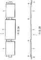
- FIG. 2A is a plan view and FIG. 2B is a side view, both showing the first non-aqueous electrolyte battery 4, second non-aqueous electrolyte battery 5 and lead 6 of the battery body 3 in a state that they are stretched out.
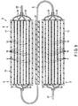
- FIG. 3 is a longitudinal cross-sectional view schematically showing an internal structure of the laminate 8 of the battery body 3.
- the first non-aqueous electrolyte battery 4 and the second non-aqueous electrolyte battery 5 have the same structure. Thus, only the structure of the first non-aqueous electrolyte battery 4 will be described.
- the same components of the second non-aqueous electrolyte battery 5 as those of the first non-aqueous electrolyte battery 4 are denoted by the same reference numerals, and descriptions about them will be omitted.
- the first non-aqueous electrolyte battery 4 includes a plurality of (four in this arrangement) negative electrodes 9, a plurality of (three in this arrangement) positive electrodes 10 and a non-aqueous electrolyte (not shown).
- the non-aqueous electrolyte is impregnated in an electrode group including the negative electrodes 9 and the positive electrodes 10.
- the non-aqueous electrolyte may be a solid polymer electrolyte or a gel polymer electrolyte.
- FIG. 4A is a longitudinal cross-sectional view of a main portion of an electrode structure of the negative electrode 9, and FIG. 4B is a longitudinal cross-sectional view of a main portion of an electrode structure of the positive electrode 10.
- the negative electrode 9 has, as shown in FIG. 4A , a negative electrode current collector 11 and negative electrode active material layers 12 stacked on both side surfaces of the negative electrode current collector 11.
- the positive electrode 10 has, as shown in FIG. 4B , a positive electrode current collector 13 and positive electrode active material layers 14 stacked on both side surfaces of the positive electrode current collector 13.
- the four negative electrodes 9 and the three positive electrodes 10 are alternately stacked and forms one laminate 15 including seven stacked electrodes in total.
- the first non-aqueous electrolyte battery 4 includes the one laminate 15.
- the negative electrode 9 is disposed in the lowermost position in FIG. 3 , and the positive electrode 10 is stacked on the negative electrode 9 with a separator 16 being interposed between them. Moreover, the negative electrode 9 is stacked on this positive electrode 10 with the separator 16 being interposed between them. After this, the remaining positive electrodes 10 and the remaining negative electrodes 9 are alternately stacked with the separator 16 being interposed between them, and the negative electrode 9 is finally stacked.
- An exterior surface of the laminate 15 is covered with an insulating layer 17 such as a separator.
- the first non-aqueous electrolyte battery 4 includes negative electrode tabs 18 and positive electrode tabs 19.
- the negative electrode tabs 18 are provided at right end portions of the four negative electrodes 9 as shown in FIG. 3
- the positive electrode tabs 19 are provided at left end portions of the three positive electrodes 10 as shown in FIG. 3 .
- the negative electrode tab 18 is formed by extending a portion of the negative electrode current collector 11 outside the insulating layer 17.
- the positive electrode tab 19 is formed by extending a portion of the positive electrode current collector 13 outside of the insulating layer 17.
- the four negative electrode tabs 18 of the first non-aqueous electrolyte battery 4 are fixed and connected to an external connection portion 20 on a negative electrode side by welding, for example.
- the three positive electrode tabs 19 of the first non-aqueous electrolyte battery 4 are fixed and connected to one end curved portion (the left end portion in FIG. 3 ) of the lead 6 by welding, for example. With these connections, the four negative electrodes 9 and three positive electrodes 10 alternately stacked and forming an electrode group of the first non-aqueous electrolyte battery 4 are connected in parallel.
- the four negative electrode tabs 18 of the second non-aqueous electrolyte battery 5 are fixed and connected to the other end curved portion (the right end portion in FIG. 3 ) of the lead 6 by welding, for example.
- the three positive electrode tabs 19 of the second non-aqueous electrolyte battery 5 are fixed and connected to the external connection portion 20 on a positive electrode side by welding, for example. With these connections, the four negative electrodes 9 and three positive electrodes 10 alternately stacked and forming an electrode group of the second non-aqueous electrolyte battery 5 are connected in parallel.
- the negative electrode 9 includes a negative electrode current collector 11 and a negative electrode layer (negative electrode active material layer 12) carried on one side surface or each of both side surfaces of the negative electrode current collector 11 and including an active material, a conductive agent and a binder.
- the negative electrode current connector 11 preferably uses an aluminum foil of pure aluminum (purity: 100%) or aluminum alloy of the purity of 98% or more.
- the aluminum alloy an alloy including, in addition to aluminum, at least one element selected from a group including iron, magnesium, zinc, manganese and silicon is preferable.
- an Al-Fe alloy, an Al-Mn based alloy and an Al-Mg based alloy can obtain a higher strength than the pure aluminum.
- a content of transition metal such as nickel, chromium or the like in the aluminum alloy is preferably set to 100 ppm or less (including 0 ppm). If the current collector is formed by, for example, an Al-Cu based alloy, the Al-Cu based alloy increases a strength of the current collector but deteriorates a corrosion resistance thereof. Therefore, the Al-Cu based alloy is not good for the current collector.
- a range of more desirable aluminum purity is in 99.95 to 98.0%.
- titanium containing oxide particles in which an average particle size of secondary particles is 2 ⁇ m or more it is possible to reduce a negative electrode pressing pressure and to reduce an elongation of the aluminum foil.
- an electron conductivity of the aluminum foil of the current collector can advantageously be increased and further, a negative electrode of low resistance can be produced by suppressing shredding of the secondary particles of titanium containing oxide.
- a negative electrode active material of the negative electrode active material layer 12 which occludes and emits lithium ions
- carbon material, graphite material, lithium alloy material, metallic oxide and metallic sulfide can be cited.
- the negative electrode active material of at least one kind of titanium containing oxide which is selected from lithium titanium oxide, titanium oxide, niobium titanium oxide and lithium-sodium-niobium-titanium oxide, and in which an electric potential of lithium ion for its occlusion/emission is in a range of 1 to 3 V in a Li electric potential reference.
- lithium titanium oxide lithium titanium oxide with a spinel structure that can be represented by the general formula Li 4+x Ti 5 O 12 (x: -1 ⁇ x ⁇ 3) ; lithium titanium oxides with a ramsdellite structure such as Li 2+x Ti 3 O 7 , Li 1+x Ti 2 O 4 , Li 1.1+x Ti 1.8 O 4 , Li 1.07+x Ti 1.86 O 4 and Li x TiO 2 (x: 0 ⁇ x) ; titanium oxides (TiO 2 as a structure before charging) with a monoclinic structure (TiO 2 (B) as a structure before charging), a rutile structure or with an anatase structure, each of which is represented by the general formula Li x TiO 2 (0 ⁇ x), may be cited.
- Niobium titanium oxide is represented by LiaTiMbNb 2 ⁇ O 7 ⁇ (0 ⁇ a ⁇ 5, 0 ⁇ b ⁇ 0.3, 0 ⁇ ⁇ ⁇ 0.3, ⁇ ⁇ ⁇ ⁇ 0.3, M is at least one element selected from Fe, V, Mo and Ta). And, these oxides may be used alone or in a mixed state. Lithium titanium oxide with a spinel structure the volume of which changes very little and which can be represented by the general formula Li 4+x Ti 5 O 12 (x: -1 ⁇ x ⁇ 3) is more desirable.
- an aluminum foil which is the same as that of the positive electrode current collector 13, instead of a conventional copper foil, can be used for the negative electrode current collector 11 so that a weight reduction and lower costs of the negative electrode current collector 11 can be achieved.
- An average particle size (diameter) of the secondary particles of the negative electrode active material is preferably larger than 5 ⁇ m. More desirably, the average particle size is 7 to 20 ⁇ m. In this range, a negative electrode of a high density can be produced while maintaining a pressure of the negative electrode pressing in low and thus, the elongation of the current collector of aluminum foil can be suppressed.
- the secondary particles of the negative electrode active material having the average particle size which is larger than 5 ⁇ m can be obtained by firstly reacting raw materials of the active material to synthesize active material precursors as first particles having an average particle size which is 1 ⁇ m or less and then by calcining first particles. During this, the raw materials of the active material is broken by using a grinder such as a ball mill or a jet mill and the active material precursors are aggregated with each other to grow them to secondary particles of a large particle size.
- the average particle size of the first particles of the negative electrode active material is preferably 1 ⁇ m or less. AS a result of this, a high-input performance (quick charge) is remarkably improved.
- the average particle size is 0.1 to 0.8 ⁇ m. It is also preferable to coat the surface of the secondary particle with a carbon material so that a resistance of the negative electrode is reduced. This can be achieved by adding precursors of carbon material into the active material precursors in a secondary particle production process and by calcining them at 500 °C or higher in an inert atmosphere.
- the secondary particles and first particles of titanium containing oxide may be mixed.
- the first particles are preferably included in 5 to 50% by volume in the negative electrode active material layer 12.
- the average particle size of the negative electrode active material is set to the above range. If the specific surface area of the negative electrode 9 is increased to 3 to 50 m 2 /g by using first particles whose average particle size exceeds 1 ⁇ m, a fall in a porosity of the negative electrode 9 becomes unavoidable. However, if the average particle size becomes smaller, the particles are more likely to aggregate and a distribution of non-aqueous electrolyte may be concentrated in the negative electrode 9 so that a depletion of the electrolyte in the positive electrode 10 may be caused. Therefore, it is desirable to set a lower limit of the average particle size of the first particles to 0.001 ⁇ m.
- the negative electrode active material desirably has the average particle size of 1 ⁇ m or less and the specific surface area by the BET method using N 2 adsorption is in a range of 3 to 200 m 2 /g. This cause an affinity of the negative electrode 9 with the non-aqueous electrolyte can further be increased.
- the specific surface area of the negative electrode is specified in the above range. If the specific surface area is less than 3 m 2 /g, an aggregation of particles becomes conspicuous, an affinity of the negative electrode 9 with a non-aqueous electrolyte decreases and an interfacial resistance of the negative electrode 9 increases. Thus, an output characteristic and charge and discharge cycle characteristic of the battery deteriorate. If the specific surface area exceeds 50 m 2 /g, on the other hand, a distribution of the non-aqueous electrolyte is concentrated in the negative electrode 9 and the shortage of the non-aqueous electrolyte is in the positive electrode 10 is caused and thus, output characteristics and charge and discharge cycle characteristic of the battery cannot be improved. A more desirable range of the specific surface area is 5 to 50 m 2 /g.
- the specific surface area of the negative electrode 9 means a surface area thereof per one gram of the negative electrode active material layer 12 (excluding the weight of the negative electrode current collector 11).
- the porosity of the negative electrode 9 (excluding the negative electrode current collector 11) is desirably set in a range of 20 to 50%. Accordingly, a high-density negative electrode 9 which is superior in the affinity with the non-aqueous electrolyte can be obtained. A more desirable range of the porosity is 25 to 40%.
- the negative electrode current collector 11 is desirably made of aluminum foil or aluminum alloy foil.
- a thickness of the aluminum foil or aluminum alloy foil is desirably 20 ⁇ m or less and more desirably 15 ⁇ m or less.
- a purity of the aluminum foil is desirably 99.99% or more.
- the aluminum alloy desirably contains at least one element such as magnesium, zinc, silicon or the like.
- a content of transition metal such as iron, copper, nickel, chromium or the like is desirably set to 100 ppm or less.
- a carbon material can be used as the conductive agent.
- a carbon material for example, acetylene black, carbon black, coke, carbon fiber, graphite, aluminum powder, TiO or the like can be cited.
- a specific surface area of the carbon material by using N 2 adsorption is desirably 10 m 2 /g or more.
- binder for example, polytetrafluoroethylene (PTFE), polyvinylidene difluoride (PVdF), fluororubber, styrene-butadiene rubber, core shell binder and the like can be cited.
- PTFE polytetrafluoroethylene
- PVdF polyvinylidene difluoride
- fluororubber fluororubber
- styrene-butadiene rubber styrene-butadiene rubber
- core shell binder core shell binder
- a compounding ratio of the active material, the conductive agent and the binder in the negative electrode 9 is desirably such that negative electrode active material is in a range of 80 to 95% by weight, the conductive agent is in a range of 3 to 18% by weight and the binder is in a range of 2 to 7% by weight.
- the negative electrode 9 is formed by suspending the above described negative electrode active material, conductive agent and binder in an appropriate solvent, by coating a negative electrode current collector 11 with the suspension, by drying the suspension and by being subjected with a warming press. And, in this case, particles of the negative electrode active material are uniformly dispersed while a loading amount of the binder is small. If the loading amount of the binder is large, a dispersibility of the particles tends to increase. However, a surface of each particle is more likely to be covered with the binder and the specific surface area of the negative electrode is made to be small. If the loading amount of the binder is small, the particles are more likely to aggregate with each other.
- the negative electrode active material layer 12 is likely to be ground so that the specific surface area of the negative electrode 9 tends to increase, or the dispersibility of the negative electrode active material layer 12 falls so that the specific surface area of the negative electrode 9 tends to decrease.
- the average particle size and specific surface area of the conductive agent can affect the specific surface area of the negative electrode. And, it is preferable that the average particle size of the conductive agent is smaller than the average particle size of the negative electrode active material layer 12 and the specific surface area of the conductive agent is larger than the specific surface area of the negative electrode active material.
- the positive electrode 10 includes a positive electrode current collector 13 and a positive electrode active material layer 14 carried on one side surface or each of both side surfaces of the positive electrode current collector 13 and including an active material, a conductive agent and a binder, etc.
- the positive electrode current connector 13 preferably uses an aluminum foil of pure aluminum (purity: 100%) or an aluminum alloy foil of the purity of 98% or more.
- the aluminum alloy an alloy including, in addition to aluminum, at least one element selected from a group including iron, magnesium, zinc, manganese and silicon is preferable.
- an Al-Fe alloy, an Al-Mn based alloy and an Al-Mg based alloy can obtain a higher strength than that of the pure aluminum.
- a content of transition metal such as nickel, chromium or the like in the aluminum alloy is preferably set to 100 ppm or less (including 0 ppm). If the positive electrode current collector 13 is formed by, for example, an Al-Cu based alloy, the strength of the current collector is increased but a corrosion resistance thereof is deteriorated. Therefore, the Al-Cu based alloy is not good for the positive electrode current collector.
- a range of more desirable aluminum purity is in 99.95 to 98.0%.
- the aluminum purity is in this range, deterioration of a high-temperature cycle life due to dissolution of an impurity element can be reduced.
- a lithium manganese composite oxide As the positive electrode active material layer 14, a lithium manganese composite oxide, a lithium nickel composite oxide, a lithium cobalt aluminum composite oxide, a lithium nickel cobalt manganese composite oxide, a spinel-type lithium manganese nickel composite oxide, a lithium manganese cobalt composite oxide, an olivine-type lithium iron phosphate (LiFePO 4 ), a lithium phosphoric acid manganese (LiMnPO 4 ) and the like may be cited.
- LiFePO 4 olivine-type lithium iron phosphate
- LiMnPO 4 lithium phosphoric acid manganese
- the lithium manganese composite oxides such as Li x Mn 2 O 4 or Li x MnO 2 , lithium nickel aluminum composite oxides such as Li x Ni 1-y Al y O 2 , lithium cobalt composite oxides such as Li x CoO 2 , lithium nickel cobalt composite oxides such as Li x Ni 1-y-z Co y Mn z O 2 , lithium manganese cobalt composite oxides such as Li x Mn y Co 1-y O 2 , spinel-type lithium manganese nickel composite oxides such as Li x Mn 2-y Ni y O 4 , lithium phosphorus oxides having an olivine crystal structure, such as Li x FePO 4 , Li x Fe 1-y Mn y PO 4 and Li x CoPO 4 , and fluorinated iron sulfate such as Li x FeSO 4 F are cited.
- x and y are, unless otherwise specified, preferably in a range of 0 to 1.
- the lithium nickel aluminum composite oxide, the lithium nickel cobalt manganese composite oxide or the lithium manganese cobalt composite oxide is used, a reaction with the non-aqueous electrolyte under high-temperature environment can be suppressed so that a battery life can be significantly increased.
- the lithium nickel cobalt manganese composite oxide represented by Li x Ni 1-y-z Co y Mn 2 O 2 (0 ⁇ x ⁇ 1.1, 0 ⁇ y ⁇ 0.5, and 0 ⁇ z ⁇ 0.5) is preferable. By using the lithium nickel cobalt manganese composite oxide, a high temperature durability life can be further improved.
- a conductive agent for enhancing electron conductivity and suppressing contact resistance with the positive electrode current collector 13 for example acetylene black, carbon black, graphite and the like may be cited.
- PTFE polytetrafluoroethylene
- PVdF polyvinylidene fluoride
- a compounding ratio of the positive electrode active material, the conductive agent and the binder in the positive electrode active material layer 14 is preferably that the positive electrode active material is in a range from 80% or more by weight to 95% or less by weight, the conductive agent is in a range from 3% or more by weight to 18% or less by weight, and the binder is in a range from 2% or more by weight to 7% or less by weight.
- the compounding ratio of the conductive agent is 3% or more by weight, the above described effect can be achieved.
- the compounding ratio of the conductive agent is 18% or less by weight, decomposition of the non-aqueous electrolyte on a surface of the conductive agent while the battery is preserved in high temperature can be reduced.
- the compounding ratio of the binder is 2% or more by weight, sufficient electrode strength can be obtained.
- the compounding ratio of the binder is 7% or less by weight, an insulating portion of the positive electrode 10 can be reduced.
- the positive electrode 10 is produced by, for example, suspending the positive electrode active material, the conductive agent and the binder in an appropriate solvent, by applying this suspension on the positive electrode current collector 13, by drying the applied suspension and by pressing it.
- a positive electrode pressing pressure is preferably in a range from 0.15 ton/mm to 0.3 ton/mm. If the positive electrode pressing pressure is in this range, it is preferable because an adhesion (peel strength) of the positive electrode active material layer 14 to the positive electrode current collector 13 of the aluminum foil is enhanced, and, at the same time, the elongation percentage of the aluminum foil of the positive electrode current collector 13 is 20% or less.
- the lead 6 is a sheet arranged to face one side surface of the non-aqueous electrolyte battery and having an area larger than an area of the one side surface of the non-aqueous electrolyte battery.
- a pure aluminum foil (having a purity of 100%) or an aluminum alloy foil having a purity of 98% or more is preferably used.
- the aluminum alloy preferably contains, in addition to aluminum, one or more elements selected from the group consisting of iron, magnesium, zinc, manganese, and silicon.
- an Al-Fe alloy, an Al-Mn-based alloy and an Al-Mg-based alloy can obtain higher strength than that of aluminum.
- a content of transition metal such as nickel, chromium and the like in the aluminum alloy is preferably 100 ppm or less (including 0 ppm).
- an Al-Cu-based alloy enhances a strength but deteriorates a corrosion resistance. Therefore, the Al-Cu-based alloy is unsuitable for a lead.
- the aluminum purity is more preferably in a range from 99.95% to 98.0%.
- a thickness of the lead made of the aluminum having the above described aluminum purity is preferably 20 ⁇ m or more. However, if the thickness is too large, it becomes hard to handle the lead and its capacity per volume is reduced. Thus, the thickness is preferably 1 mm or less, more preferably 500 ⁇ m or less , and still more preferably 200 ⁇ m or less.
- a metal container or a laminate film container may be used as a container (the outer case 2) storing the laminate 8 of the battery body 3.
- a metal container or a laminate film container may be used as the metal container.
- the metal container a rectangular or cylindrical metal can formed of aluminum, aluminum alloy, iron, stainless steel or the like may be used.
- a plate thickness of the container is preferably 0.5 mm or less, and more preferably 0.3 mm or less.
- the laminate film a multilayered film in which an aluminum foil is covered with a resin film may be cited.
- a resin of the film a polymer such as polypropylene (PP), polyethylene (PE), nylon, polyethylene terephthalate (PET) or the like may be used.
- a thickness of the laminated film is preferably 0.2 mm or less.
- the purity of the aluminum foil is preferably 99.5% or more.
- the aluminum alloy forming the metal can preferably has an aluminum purity of 99.8% or less and contains elements such as manganese, magnesium, zinc, silicon and the like.
- Such an aluminum alloy as described above remarkably increase a strength of the metal can so that a wall thickness of the can be reduced. As a result, it is possible to achieve a thin and lightweight battery which has high output and is superior in heat radiation.
- the lead 6 is disposed between the first non-aqueous electrolyte battery 4 and the second non-aqueous electrolyte battery 5 in the outer casing 2, and the lead 6 has an area larger than each of the areas of the first non-aqueous electrolyte battery 4 and second non-aqueous electrolyte battery 5.
- the lead 6 can prevent the liquid junction between the first non-aqueous electrolyte battery 4 and the second non-aqueous electrolyte battery 5, both stacked in the outer case 2, caused by the non-aqueous electrolyte leaking from the first non-aqueous electrolyte battery 4 and/or the second non-aqueous electrolyte battery 5.
- FIGS. 5A, 5B and 6 show a second arrangement.
- An assembled battery 101 of this arrangement has five non-aqueous electrolyte batteries 102, each having the same structure as that of the first non-aqueous electrolyte battery 4 (or the second non-aqueous electrolyte battery 5) of the assembled battery 1 of the first arrangement (see FIGS. 1 to 4B ), and four leads 103 each having the same structure as that of the lead 6 of the first arrangement.
- a battery body 104 of this arrangement as shown in FIG. 5A , the five non-aqueous electrolyte batteries 102 are connected in series in a row with the four sheet-like leads 103 being interposed between the five non-aqueous electrolyte batteries 102 and form a serially connected body 105.
- the linear serially connected body 105 is alternately folded between each non-aqueous electrolyte battery 102 and each sheet-like lead 103 to stack the five non-aqueous electrolyte batteries 102 and the four sheet-like leads 103 alternately and to form a laminate 106, as shown in FIG. 5B .
- the linear serially connected body 105 formed into the laminate 106 is stored in an outer case 107, as shown in FIG. 6 .
- both end portions of each lead 103 for connecting tabs 18 and 19 of adjacent non-aqueous electrolyte battery 102 are curved and form curved portions.
- FIG. 7 shows a third arrangement.
- An assembled battery 201 of this arrangement includes the first non-aqueous electrolyte battery 4 and the second non-aqueous electrolyte battery 5, both of which are the same as those of the assembled battery 1 of the first arrangement (see FIGS. 1 to 4B ).
- a positive electrode tab stacked portion 19a in which three positive electrode tabs 19 of the first non-aqueous electrolyte battery 4 are stacked is provided.
- the positive electrode tab stacked portion 19a is fixed and connected to one side surface (the upper side surface in FIG. 7 ) of the lead 6 at its upwardly curved one end portion (the left end portion in FIG. 7 ) by welding, for example.
- a negative electrode tab stacked portion 18a in which four negative electrode tabs 18 of the second non-aqueous electrolyte battery 5 are stacked is further provided.
- the negative electrode tab stacked portion 18a is fixed and connected to the other side surface (the lower side surface in FIG. 7 ) of the lead 6 at its downwardly curved end portion (the right end portion in FIG. 7 ) by welding, for example.
- Other portions were produced as in the first arrangement.
- FIG. 8 shows a fourth arrangement.
- An assembled battery 301 of this arrangement includes the first non-aqueous electrolyte battery 4 and the second non-aqueous electrolyte battery 5 both of which are the same as those of the assembled battery 1 of the first arrangement (see FIGS. 1 to 4B ).
- a positive electrode tab stacked portion 19a in which three positive electrode tabs 19 of the first non-aqueous electrolyte battery 4 are stacked is provided.
- the positive electrode tab stacked portion 19a is fixed and connected to one side surface (the lower side surface in FIG. 7 ) of the lead 6 at its upwardly curved one end portion (the left end portion in FIG. 8 ) by welding, for example.
- a negative electrode tab stacked portion 18a in which four negative electrode tabs 18 of the second non-aqueous electrolyte battery 5 are stacked is further provided.
- the negative electrode tab stacked portion 18a is fixed and connected to the one side surface (the lower surface in FIG. 8 ) of the lead 6 at its downwardly curved other end portion (the right end portion in FIG. 8 ) by welding, for example. Other portions were produced as in the first arrangement.
- FIG. 9 shows a fifth arrangement.
- insulating layers 31 each made of alumina particles and each having a thickness of 3 ⁇ m are provided on both side surfaces of the aluminum foil of the lead 6 disposed between the first non-aqueous electrolyte battery 4 and the second non-aqueous electrolyte battery 5 of the assembled battery 1 of the first arrangement (see FIGS. 1 to 4B ).
- Other portions were produced as in the first arrangement.
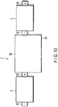
- FIGS. 10 to 12 show a sixth arrangement.
- a shape of a lead 32 between the first non-aqueous electrolyte battery 4 and the second non-aqueous electrolyte battery 5 is different from that of the lead 6 between the first non-aqueous electrolyte battery 4 and the second non-aqueous electrolyte battery 5 in the assembled battery 1 of the first arrangement (see FIGS. 1 to 4B ).
- the lead 32 of this arrangement is provided with an extending portion 33 at one of both sides thereof other than the other both sides of the lead 32 to which the positive electrode tab 19 of the first non-aqueous electrolyte battery 4 and the negative electrode tab 18 of the second non-aqueous electrolyte battery 5 are connected respectively.
- the extending portion 33 elongates in a direction (the downward direction in FIG. 10 ) other than directions along which the positive electrode tab 19 of the first non-aqueous electrolyte battery 4 and the negative electrode tab 18 of the second non-aqueous electrolyte battery 5 extend.
- FIG. 10 is a substantially plan view schematically showing the first non-aqueous electrolyte battery 4, second non-aqueous electrolyte battery 5 and lead 32 of an assembled battery of this arrangement in an exploded state.
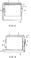
- FIG. 11 is a perspective view showing a laminate 8 in a state in which the first non-aqueous electrolyte battery 4, second non-aqueous electrolyte battery 5 and lead 32 of the present assembled battery are folded and stacked with each other.
- the extending portion 33 of the lead 32 is bent at right angles to form an L-shaped bent portion 34.
- Other portions were produced as in the first arrangement.
- FIGS. 13 and 14 show a seventh arrangement.
- FIG. 13 is a perspective view showing a state in which a battery body 35 of this arrangement is provided by stacking the laminates 8, each including the first and second non-aqueous electrolyte batteries 4 and 5 and lead 32 of an assembled battery of the sixth arrangement (see FIGS. 10 to 12 ), in multiples.
- FIG. 14 is a cross-sectional view schematically showing a state in which the battery body 35 of FIG. 13 is stored in an outer case 36.
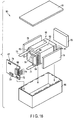
- FIG. 15 shows an eighth arrangement.
- An assembled battery 401 of this arrangement has a first non-aqueous electrolyte battery 402 and the second non-aqueous electrolyte battery 5.
- the first non-aqueous electrolyte battery 402 has a structure which is different from that of the first non-aqueous electrolyte battery 4 of the assembled battery 1 of the first arrangement (see FIGS. 1 to 4B ), and the second non-aqueous electrolyte battery 5 has the same structure as that of the first non-aqueous electrolyte battery 4 of the first arrangement.
- the first non-aqueous electrolyte battery 402 of this arrangement includes four positive electrodes 403, three negative electrodes 404 and six separators 406.
- the four positive electrodes 403 and the three negative electrodes 404 are alternately stacked with the six separators 406 being interposed between them to form one laminate 405 including seven stacked electrodes in total.
- the laminate 405 provides the first non-aqueous electrolyte battery 402.
- the first positive electrode 403 is disposed in a lowermost position in FIG. 15
- the first negative electrode 404 is stacked on the first positive electrode 403 with the separator 406 being interposed between them.
- the second positive electrode 403 is stacked on the first negative electrode 404 with the separator 406 being interposed between them.
- the second negative electrode 404 is stacked on the second positive electrode 403 with the separator 406 being interposed between them.
- the third positive electrode 403 is stacked on the second negative electrode 404 with the separators 406 between them.
- the third negative electrode 404 is stacked on the third positive electrode 403 with the separators 406 between them.
- the fourth positive electrode 403 is stacked on the third negative electrode 404 with the separators 406 between them.
- An exterior surface of the laminate 405 is covered with an insulating layer 407 such as a separator.
- the first non-aqueous electrolyte battery 402 includes positive electrode tabs 408 and negative electrode tabs 409.
- the positive electrode tabs 408 are provided at left end portions of the four positive electrodes 403 in FIG. 15
- the negative electrode tabs 409 are provided at right end portions of the three negative electrodes 404 in FIG. 15 .
- the four positive electrode tabs 408 of the first non-aqueous electrolyte battery 402 are fixed and connected to one end curved portion (the left end portion in FIG. 15 ) of the lead 6 by welding, for example.
- the three negative electrode tabs 409 of the first non-aqueous electrolyte battery 402 are fixed and connected to an external connection portion 20 on a negative electrode side by welding, for example. With these connections, the four positive electrodes 403 and three negative electrodes 404 alternately stacked and forming an electrode group of the first non-aqueous electrolyte battery 402 are connected in parallel. Other portions were produced as in the first arrangement.
- the two adjacent non-aqueous electrolyte batteries may be connected with each other by a plurality of leads interposed between the two adjacent non-aqueous electrolyte batteries.
- at least one lead has an area larger than an area of a side surface of each of the two adjacent non-aqueous electrolyte batteries, the side surface being opposing to the at least one lead.
- each of the negative electrode 9 and the positive electrode 10 is a rectangular flat plate each having a size of 70 mm ⁇ 90 mm.
- the lead 6 is formed of a rectangular flat plate-shaped aluminum foil having a size of 74 mm ⁇ 100 mm.
- the four negative electrode tabs 18 of the first non-aqueous electrolyte battery 4 are fixed and connected to the external connection portion 20 on the negative electrode side by welding.
- the three positive electrode tabs 19 of the first non-aqueous electrolyte battery 4 are fixed and connected to one end portion (the left end portion in FIG. 3 ) of the lead 6 by welding. With these connections, the four negative electrodes 9 and three positive electrodes 10 alternately stacked and forming an electrode group of the first non-aqueous electrolyte battery 4 are connected in parallel.
- the four negative electrode tabs 18 of the second non-aqueous electrolyte battery 5 are fixed and connected to the other end portion (the right end portion in FIG. 3 ) of the lead 6 by welding, for example.
- the three positive electrode tabs 19 of the second non-aqueous electrolyte battery 5 are fixed and connected to the external connection portion 20 on the positive electrode side by welding. With these connections, the four negative electrodes 9 and three positive electrodes 10 alternately stacked and forming an electrode group of the second non-aqueous electrolyte battery 5 are connected in parallel.
- connections to the tabs of the laminate of each of the first non-aqueous electrolyte battery 4 and second non-aqueous electrolyte battery 5 are performed at the midpoint in all of the tabs by welding. After welding of each tab, the first non-aqueous electrolyte battery 4, the second non-aqueous electrolyte battery 5 and an aluminum foil of the leas 6 are connected in series in a row, then folded, and encased, whereby a test cell according to Example 1 is produced.
- the assembled battery 101 of the second arrangement is used.
- Five laminates each of which is the first non-aqueous electrolyte battery 4 described in Example 1 are provided, and they are connected in series as in Example 1. (See FIGS. 5A, 5B , and 6 )
- the assembled battery 201 of the third arrangement is used. (See FIG. 7 .)
- the assembled battery 301 of the fourth arrangement is used. (See FIG. 8 )
- the assembled battery of the fifth arrangement is used.
- An assembled battery prepared by producing insulating layers 31 of solid electrolyte particles (for example, Li 7 La 3 Zr 2 O 12 (LLZ)) with a thickness of 3 ⁇ m on both side surfaces of the aluminum foil of the lead 6 of the assembled battery of example 5 is used. Other portions are produced as in the first arrangement. (See FIG. 9 )
- An assembled battery prepared by producing insulating layers of an acrylic resin with a thickness of 1 ⁇ m on both side surfaces of the aluminum foil of the lead 6 of the assembled battery of example 5 is used. Other portions are produced as in the first arrangement. (See FIG. 9 )
- the assembled battery of the sixth arrangement is used, in which the lead 32 is a rectangular flat plate-shaped aluminum foil having a size of 90 mm ⁇ 100 mm and one of two longitudinally extending side portions of the rectangular flat plate is bent into an L-shape by 16 mm. (See FIGS. 10 to 12 .)
- the assembled battery 401 of the eighth arrangement is used, in which the laminate of the first non-aqueous electrolyte battery 402 has the positive electrode at its uppermost layer and the laminate of the second non-aqueous electrolyte battery 5 has the negative electrode at the uppermost layer. Other portions are produced as in the first arrangement. (See FIG. 15 )
- Example 1 Battery capacity (Ah) Average operating voltage (V) Volume energy density (Wh/L) Weight energy density (Wh/kg)
- Example 1 1 5 150 75
- Example 2 1 12.5 180 90
- Example 3 1 5 150 75
- Example 4 1 5 150 75
- Example 5 1 5 140 74
- Example 6 1 5 140
- Example 7 1 5 130
- Example 8 1 5 150
- Example 9 1 5 150
- FIG. 16 is an exploded perspective view schematically showing a structure of a battery pack 90.
- FIG. 17 is a block diagram showing an electric circuit of the battery pack 90 in FIG. 16 .
- the battery pack 90 shown in FIGS. 15 and 16 includes a plurality of assembled batteries 91, each of which is the assembled battery 1 according to the first arrangement and described with reference to FIG. 1 .
- the battery pack 90 can further be provided with a protective circuit.
- the protective circuit is used to control a charge and discharge of the assembled batteries 91.
- a circuit contained in a device for example, an electronic device, an automobile and the like
- using the battery pack 90 as a power supply can also be used as the protective circuit of the battery pack 90.
- the battery pack 90 according to the arrangement can further be provided with external terminals for electrifying.
- the external terminals for electrifying are used to output a current from the assembled batteries 91 of the battery pack 90 to an outside thereof and also to input a current from the outside thereof into the assembled batteries 91 of the battery pack 90.
- a current from the assembled batteries 91 of the battery pack 90 is supplied to the outside through the external terminals for electrifying.
- a current for charging including regenerative energy from a power of an automobile
- the plurality of assembled batteries 91 are stacked such that negative electrode terminals 63 and positive electrode terminals 64 extending to the outside are aligned in the same direction, and are fastened with each other by an adhesive tape 65 to constitute a non-aqueous electrolyte battery 66. As shown in FIG. 17 , these assembled batteries 91 are electrically connected to each other in series.
- a printed wiring board 67 is arranged to oppose to side surfaces of the assembled batteries 91 from which the negative electrode terminals 63 and positive electrode terminals 64 of the assembled batteries 91 extend.
- a thermistor 68, a protective circuit 69 and a terminal 70 for electrifying to external devices are mounted on the printed wiring board 67.
- An electrical insulating plate (not shown) for avoiding unnecessary connection to wires of the non-aqueous electrolyte battery 66 is mounted on a surface of the printed wiring board 67 opposing to the non-aqueous electrolyte battery 66.
- a positive electrode lead 71 is connected to the positive electrode terminal 64 positioned in one of the both outer sided assembled batteries 91 of the non-aqueous electrolyte battery 66, and the tip end thereof is inserted into a positive electrode connector 72 of the printed wiring board 67 and is electrically connected thereto.
- a negative electrode lead 73 is connected to the negative electrode terminal 63 positioned in the other of the both outer sided assembled batteries 91 of the non-aqueous electrolyte battery 66, and the tip end thereof is inserted into a negative electrode connector 74 of the printed wiring board 67 and is electrically connected thereto.
- These connectors 72 and 74 are connected to the protective circuit 69 through wires 75 and 76 formed on the printed wiring board 67.
- the thermistor 68 detects a temperature of each assembled battery 91 and a detection signal corresponding to the temperature is sent to the protective circuit 69.
- the protective circuit 69 is used to control a charge and discharge of the assembled battery 91.
- the protective circuit 69 can cut off a positive-side wire 77a and negative-side wire 77b between the protective circuit 69 and the terminal 70 for electrifying to external devices under predetermined conditions.
- One of the predetermined conditions is, for example, when the temperature detected by the thermistor 68 is equal to or higher than a predetermined temperature.
- the other of the predetermined conditions is when an over-charge, an over-discharge, an over-current or the like of the assembled battery 91 is detected.
- the detection of an over-charge or the like is carried out for each of the assembled batteries 91 or the whole of the non-aqueous electrolyte battery 66.
- a battery voltage, a positive electrode potential or a negative electrode potential may be detected.
- a lithium electrode used as a reference electrode is inserted into each of the assembled batteries 91.
- a wire 78 for voltage detection is connected to each of the assembled batteries 91.
- a detection signal is sent to the protective circuit 69 through these wires 78.
- a protective sheet 79 made of rubber or resin is arranged on each of three side surfaces of the non-aqueous electrolyte battery 66 excluding one side surface from which the negative electrode terminal 63 and the positive electrode terminal 64 protrude.
- the non-aqueous electrolyte battery 66 together with the protective sheets 79 and the printed wiring board 67 is housed in a container 80. That is, the protective sheet 79 is arranged on each of both inner side surfaces of the container 80 extending in a long side direction and one of both inner side surfaces of the container 80 extending in a short side direction, and the printed wiring board 67 is arranged on the other of the both inner side surfaces. That is, the non-aqueous electrolyte battery 66 surrounded by the protective sheets 79 and the printed wiring board 67 is positioned in an inner space of the container 80. An opening of the container 80 is covered with a cover 81.
- a heat-shrinkable tape may be used to fix the assembled batteries 91 of the non-aqueous electrolyte battery 66.
- the heat-shrinkable tape is wound around the non-aqueous electrolyte battery 66 after the protective sheets 79 are arranged on the both longitudinal side surfaces of the non-aqueous electrolyte battery 66, and then the heat-shrinkable tape is thermally shrunk to tie the assembled batteries 91 of the non-aqueous electrolyte battery 66 together with the protective sheets 79 together.
- the assembled batteries 91 are connected in series, but the assembled batteries 91 may be connected in parallel to increase a battery capacity of the non-aqueous electrolyte battery 66.
- a plurality of the battery packs 90 may be connected in series and/or in parallel.
- the battery pack 90 is appropriately changed according to its uses.
- the battery pack 90 is preferably used for a use that requires a good cycle characteristic under a large current.
- a power supply of a digital camera and an on-board power supply used for vehicles such as two-wheeled to four-wheeled hybrid electric vehicles, two-wheeled to four-wheeled electric vehicles and motor-assisted bicycles can be cited.
- the battery pack 90 is particularly suitable for on-board uses. When the battery pack 90 is mounted on a vehicle and is used as a power source thereof, the battery pack 90 may recover a regenerative energy regenerated from a power of the vehicle.
- FIG. 18 shows an example of an automobile 100 that is a kind of a vehicle and that comprises the battery pack 90 (see FIG. 16 ) of the non-aqueous electrolyte battery 66 according to the first arrangement.
- the battery pack 90 is installed in an engine room of the automobile 100.
- the installing position of the battery pack 90 is not limited to the engine room.
- the battery pack 90 may also be positioned in a rear part of the automobile 100 or under seats of the automobile 100.
- the battery pack 90 is configured to recover a regenerative energy of a power of the vehicle.
- a motor/generator M/G is coupled to the wheels of the automobile 100, and the battery pack 90 is combined with a control unit 102 connected to the motor/generator M/G.
- the control unit 102 is configured to selectively supply an electric power of the battery pack 90 to the motor/generator M/G or recover a regenerative energy of a power of the vehicle to the battery pack 90.
- an assembled battery which can prevent liquid junction between non-aqueous electrolyte batteries when a plurality of non-aqueous electrolyte batteries and leads are connected in series in a container for storing a battery body, a battery pack which comprises the assembled batteries, and a vehicle which comprises the battery pack.
Landscapes
- Chemical & Material Sciences (AREA)
- Chemical Kinetics & Catalysis (AREA)
- Electrochemistry (AREA)
- General Chemical & Material Sciences (AREA)
- Engineering & Computer Science (AREA)
- Manufacturing & Machinery (AREA)
- Power Engineering (AREA)
- Mechanical Engineering (AREA)
- Transportation (AREA)
- Sustainable Development (AREA)
- Sustainable Energy (AREA)
- Life Sciences & Earth Sciences (AREA)
- General Physics & Mathematics (AREA)
- Physics & Mathematics (AREA)
- Condensed Matter Physics & Semiconductors (AREA)
- Dispersion Chemistry (AREA)
- Microelectronics & Electronic Packaging (AREA)
- Inorganic Chemistry (AREA)
- Secondary Cells (AREA)
- Materials Engineering (AREA)
- Connection Of Batteries Or Terminals (AREA)
- Battery Mounting, Suspending (AREA)
- Sealing Battery Cases Or Jackets (AREA)
- Battery Electrode And Active Subsutance (AREA)
- Electric Propulsion And Braking For Vehicles (AREA)
- Arrangement Or Mounting Of Propulsion Units For Vehicles (AREA)
- Charge And Discharge Circuits For Batteries Or The Like (AREA)
Abstract
Description
- Arrangements described herein relate generally to an assembled battery.
- In recent years, research and development of lithium ion secondary batteries is actively conducted as a high energy-density battery. Lithium ion secondary batteries are expected to be used as an electric source of vehicles such as hybrid vehicles and electric vehicles or as an uninterruptible power supply of mobile phone base stations. However, even if a cell of a lithium ion secondary battery is made larger in size, the voltage obtained from the cell of the lithium ion secondary battery is a low voltage of about 3.7 V. Thus, to obtain a high output from a power supply using the cell of the lithium ion secondary battery, a power supply in which many cells of the lithium ion secondary battery are connected in series needs to be used. As a result, a size of the power supply grows becomes larger.
- A bipolar battery is proposed as a cell that can be made smaller in size relative to its output. The bipolar battery uses a plurality of bipolar electrodes, each of which includes a current collector, a positive electrode active material layer formed on one side surface of the current collector, and a negative electrode active material layer formed on the other side surface of the current collector. These bipolar electrodes are arranged with an electrolytic layer being interposed between them and electrically connected in series. Since the plural bipolar electrodes are electrically connected in series in the bipolar battery, high power of a high-voltage and constant current can be obtained and further an electric resistance in the battery is small.
- A lithium ion secondary battery uses a liquid electrolyte. And, positive electrodes and negative electrodes are repeated in one cell of the bipolar battery. Thus, if the liquid electrolyte used for the lithium ion secondary battery is applied to the bipolar battery, a short-circuit (liquid junction) may be caused by ionic conduction between the positive electrode and the negative electrode. Therefore, a structure of the cell of the lithium ion secondary battery using the liquid electrolyte cannot be adopted as a structure of the cell of the bipolar battery.
- Heretofore, a bipolar battery using a polymeric solid electrolyte that does not include a liquid electrolyte has been proposed. Since the bipolar battery with this structure does not use the liquid electrolyte, there is no possibility of the short-circuit (liquid junction) due to the ionic conduction of the liquid electrolyte between the plurality of bipolar electrolytes. In general, however, an ionic conductance of the solid electrolyte is about 1/10 to 1/100 of that of the liquid electrolyte and is very low in comparison with that of the liquid electrolyte. Therefore, an output density of the bipolar battery in this structure is low and the bipolar battery in this structure is not yet in actual use.
- In view of the above circumstances, a bipolar battery using a gel electrolyte obtained by making a liquid electrolyte being semisolid is proposed. The gel electrolyte is produced by soaking an electrolytic solution into a polymer such as polyethylene oxide (PEO), polyvinylidene difluoride (PVdF), etc. Since the gel electrolyte has a high ionic conductivity, an output density of a bipolar battery using the gel electrolyte can also be expected to be high.
- On the other hand, there remains a problem to increase a size of the bipolar battery (to realize a higher energy density of the bipolar battery). As a method for realizing a higher energy density of the bipolar battery, there are considered a method in which electrode areas of positive and negative electrodes are increased and a method in which small-area bipolar type unit cells are connected in parallel. As one effective method, a method in which parallel-connected bodies (stacked bodies) are produced and the stacked bodies are connected in series inside a container for storing a battery body is considered. However, in this effective method, there is a large possibility in which the stacked bodies are in contact with each other to cause short circuit.
-
-
FIG. 1 is a cross-sectional view schematically showing the entire structure of an assembled battery of a first arrangement; -
FIG. 2A is a plan view schematic showing the assembled battery of the first arrangement in a state in which first and second non-aqueous electrolyte batteries and lead of the assembled battery of the first arrangement are spread out; -
FIG. 2B is a side view of the assembled battery shown inFIG. 2A ; -
FIG. 3 is a longitudinal cross-sectional view schematically showing an internal structure of a laminate of each of the first and second non-aqueous electrolyte batteries of the assembled battery of the first arrangement; -
FIG. 4A is a longitudinal cross-sectional view schematically showing a structure of a main portion of a negative electrode of each of the first and second non-aqueous electrolyte batteries of the assembled battery of the first arrangement; -
FIG. 4B is a longitudinal cross-sectional view schematically showing a structure of a main portion of a positive electrode of each of the first and second non-aqueous electrolyte batteries of the assembled battery of the first arrangement; -
FIG. 5A is a plan view schematically showing an assembled battery of a second arrangement in a state in which non-aqueous electrolyte batteries and leads are spread out; -
FIG. 5B is a side view of the non-aqueous electrolyte batteries and leads of the assembled battery of the second arrangement in a state in which a group of the non-aqueous electrolyte batteries and leads is folded to stack the batteries with one of the leads being interposed between them; -
FIG. 6 is a cross-sectional view schematically showing a state in which the assembled battery of the second arrangement is stored in an outer case; -
FIG. 7 is a longitudinal cross-sectional view schematically showing internal structures of laminates of an assembled battery of a third arrangement; -
FIG. 8 is a longitudinal cross-sectional view schematically showing internal structures of laminates of an assembled battery of a fourth arrangement; -
FIG. 9 is a longitudinal cross-sectional view schematically showing internal structures of laminates of an assembled battery of a fifth arrangement; -
FIG. 10 is a plan view schematically showing an assembled battery of a sixth arrangement in a state in which first and second non-aqueous electrolyte batteries and a lead are spread; -
FIG. 11 is a perspective view schematically showing the assembled battery of the sixth arrangement in a state in which a group of the first and second non-aqueous electrolyte batteries and the lead is folded and the batteries and the lead are stacked; -
FIG. 12 is a perspective view schematically showing a laminate of the assembled battery of the sixth arrangement in a state in which the group of the first and second non-aqueous electrolyte batteries and the lead is folded and the batteries and the lead are stacked and further a part of the lead is bent; -
FIG. 13 is a perspective view schematically showing an assembled battery of a seventh arrangement in a state in which a group of non-aqueous electrolyte batteries and leads is folded and the batteries and the leads are stacked; -
FIG. 14 is a cross-sectional view schematically showing a state in which the assembled battery of the seventh arrangement is stored in an outer case; -
FIG. 15 is a longitudinal cross-sectional view schematically showing internal structures of laminates of an assembled battery of an eighth arrangement; -
FIG. 16 is an exploded perspective view schematically showing a structure of a battery pack using the assembled batteries of the first arrangement; -
FIG. 17 is a block diagram schematically showing an electric circuit of the battery pack ofFIG. 16 ; and -
FIG. 18 is a view schematically showing an automobile of an arrangement of a vehicle in which the battery pack ofFIG. 16 is mounted. - An assembled battery according to one arrangement comprises a plurality of non-aqueous electrolyte batteries laminated with each other and at least one lead being interposed between two adjacent non-aqueous electrolyte batteries. The at least one lead is connected to the two adjacent non-aqueous electrolyte batteries and has an area larger than an area of a side surface of each of the two adjacent non-aqueous electrolyte batteries, the side surface being opposing to the at least one lead. Each non-aqueous electrolyte battery includes at least one positive electrode, at least one negative electrode and a non-aqueous electrolyte. The at least one positive electrode includes a positive electrode current collector and positive electrode active material layers provided on both side surfaces of the positive electrode current collector. The at least one negative electrode includes a negative electrode current collector and negative electrode active material layers provided on both side surfaces of the negative electrode current collector.
- Hereinafter, assembled batteries which relate to various arrangements will be described with reference to drawings. The same reference numerals are attached to common components throughout the various arrangements and a duplicate description thereof is omitted. Each figure is a schematic view to describe an arrangement and to promote an understanding thereof. A shape, dimensions or scale ratios of an arrangement shown in each figure is different from a shape, dimensions or scale ratios of an actual apparatus. The shape, dimensions or scale ratios of the actual apparatus may be appropriately changed in consideration of descriptions below and publicly known technology.
-
FIGS. 1 to 4B show a first arrangement.FIG. 1 is a cross-sectional view schematically showing the entire structure of an assembledbattery 1 of the first arrangement. The assembledbattery 1 of this arrangement includes anouter case 2 and abattery body 3 stored in theouter case 2. Theouter case 2 may have a structure to be described later and is formed of, for example, a laminate film in which a metal layer is interposed between two resin films. - In the
battery body 3, two non-aqueous electrolyte batteries (a firstnon-aqueous electrolyte battery 4 and a second non-aqueous electrolyte battery 5) are stacked, and a sheet-like lead 6 is arranged between the stacked firstnon-aqueous electrolyte battery 4 and secondnon-aqueous electrolyte battery 5, the sheet-like lead 6 having an area larger than an area of a side surface of each of the first and secondnon-aqueous electrolyte batteries like lead 6. Here, thelead 6 is formed of, for example an aluminum foil. When the firstnon-aqueous electrolyte battery 4 and the secondnon-aqueous electrolyte battery 5 are stacked, they may not be in contact with each other, and they may not be in close contact with thelead 6 arranged in a gap between them. - In the
battery body 3 of this arrangement, as shown inFIGS. 2A and 2B , the firstnon-aqueous electrolyte battery 4 and the secondnon-aqueous electrolyte battery 5 are arranged on both sides of thelead 6, and they are electrically connected in series in a row so that a serially connectedbody 7 is formed. The linear serially connectedbody 7 is alternately folded and stacked into alaminate 8, and thelaminate 8 is stored in theouter case 2, as shown inFIG. 1 . - In the
laminate 8 of this arrangement, the firstnon-aqueous electrolyte battery 4 is disposed above thelead 6 and the secondnon-aqueous electrolyte battery 5 is disposed below thelead 6.FIG. 2A is a plan view andFIG. 2B is a side view, both showing the firstnon-aqueous electrolyte battery 4, secondnon-aqueous electrolyte battery 5 and lead 6 of thebattery body 3 in a state that they are stretched out. -
FIG. 3 is a longitudinal cross-sectional view schematically showing an internal structure of thelaminate 8 of thebattery body 3. In this arrangement, the firstnon-aqueous electrolyte battery 4 and the secondnon-aqueous electrolyte battery 5 have the same structure. Thus, only the structure of the firstnon-aqueous electrolyte battery 4 will be described. The same components of the secondnon-aqueous electrolyte battery 5 as those of the firstnon-aqueous electrolyte battery 4 are denoted by the same reference numerals, and descriptions about them will be omitted. - The first
non-aqueous electrolyte battery 4 includes a plurality of (four in this arrangement)negative electrodes 9, a plurality of (three in this arrangement)positive electrodes 10 and a non-aqueous electrolyte (not shown). The non-aqueous electrolyte is impregnated in an electrode group including thenegative electrodes 9 and thepositive electrodes 10. - The non-aqueous electrolyte may be a solid polymer electrolyte or a gel polymer electrolyte.
-
FIG. 4A is a longitudinal cross-sectional view of a main portion of an electrode structure of thenegative electrode 9, andFIG. 4B is a longitudinal cross-sectional view of a main portion of an electrode structure of thepositive electrode 10. Thenegative electrode 9 has, as shown inFIG. 4A , a negative electrode current collector 11 and negative electrode active material layers 12 stacked on both side surfaces of the negative electrode current collector 11. Thepositive electrode 10 has, as shown inFIG. 4B , a positive electrodecurrent collector 13 and positive electrode active material layers 14 stacked on both side surfaces of the positive electrodecurrent collector 13. The fournegative electrodes 9 and the threepositive electrodes 10 are alternately stacked and forms onelaminate 15 including seven stacked electrodes in total. And, the firstnon-aqueous electrolyte battery 4 includes the onelaminate 15. In the laminate 15, thenegative electrode 9 is disposed in the lowermost position inFIG. 3 , and thepositive electrode 10 is stacked on thenegative electrode 9 with aseparator 16 being interposed between them. Moreover, thenegative electrode 9 is stacked on thispositive electrode 10 with theseparator 16 being interposed between them. After this, the remainingpositive electrodes 10 and the remainingnegative electrodes 9 are alternately stacked with theseparator 16 being interposed between them, and thenegative electrode 9 is finally stacked. An exterior surface of the laminate 15 is covered with an insulatinglayer 17 such as a separator. - The first
non-aqueous electrolyte battery 4 includesnegative electrode tabs 18 andpositive electrode tabs 19. Thenegative electrode tabs 18 are provided at right end portions of the fournegative electrodes 9 as shown inFIG. 3 , and thepositive electrode tabs 19 are provided at left end portions of the threepositive electrodes 10 as shown inFIG. 3 . Thenegative electrode tab 18 is formed by extending a portion of the negative electrode current collector 11 outside the insulatinglayer 17. Similarly, thepositive electrode tab 19 is formed by extending a portion of the positive electrodecurrent collector 13 outside of the insulatinglayer 17. - The four
negative electrode tabs 18 of the firstnon-aqueous electrolyte battery 4 are fixed and connected to anexternal connection portion 20 on a negative electrode side by welding, for example. The threepositive electrode tabs 19 of the firstnon-aqueous electrolyte battery 4 are fixed and connected to one end curved portion (the left end portion inFIG. 3 ) of thelead 6 by welding, for example. With these connections, the fournegative electrodes 9 and threepositive electrodes 10 alternately stacked and forming an electrode group of the firstnon-aqueous electrolyte battery 4 are connected in parallel. - The four
negative electrode tabs 18 of the secondnon-aqueous electrolyte battery 5 are fixed and connected to the other end curved portion (the right end portion inFIG. 3 ) of thelead 6 by welding, for example. The threepositive electrode tabs 19 of the secondnon-aqueous electrolyte battery 5 are fixed and connected to theexternal connection portion 20 on a positive electrode side by welding, for example. With these connections, the fournegative electrodes 9 and threepositive electrodes 10 alternately stacked and forming an electrode group of the secondnon-aqueous electrolyte battery 5 are connected in parallel. - In this arrangement, when an electrical resistance of each of the first
non-aqueous electrolyte battery 4 and secondnon-aqueous electrolyte battery 5 is represented by RA and an electrical resistance of thelead 6 is represented by RB, these electrical resistances RA and RB are so set such that RA≥RB. - Next, the components of the assembled
battery 1 of this arrangement will be described in more detail. - The
negative electrode 9 includes a negative electrode current collector 11 and a negative electrode layer (negative electrode active material layer 12) carried on one side surface or each of both side surfaces of the negative electrode current collector 11 and including an active material, a conductive agent and a binder. - The negative electrode current connector 11 preferably uses an aluminum foil of pure aluminum (purity: 100%) or aluminum alloy of the purity of 98% or more. As the aluminum alloy, an alloy including, in addition to aluminum, at least one element selected from a group including iron, magnesium, zinc, manganese and silicon is preferable. For example, an Al-Fe alloy, an Al-Mn based alloy and an Al-Mg based alloy can obtain a higher strength than the pure aluminum. On the other hand, a content of transition metal such as nickel, chromium or the like in the aluminum alloy is preferably set to 100 ppm or less (including 0 ppm). If the current collector is formed by, for example, an Al-Cu based alloy, the Al-Cu based alloy increases a strength of the current collector but deteriorates a corrosion resistance thereof. Therefore, the Al-Cu based alloy is not good for the current collector.
- A range of more desirable aluminum purity is in 99.95 to 98.0%. In the present arrangement, by using titanium containing oxide particles in which an average particle size of secondary particles is 2 µm or more, it is possible to reduce a negative electrode pressing pressure and to reduce an elongation of the aluminum foil. As a result of this, an electron conductivity of the aluminum foil of the current collector can advantageously be increased and further, a negative electrode of low resistance can be produced by suppressing shredding of the secondary particles of titanium containing oxide.
- As a negative electrode active material of the negative electrode
active material layer 12, which occludes and emits lithium ions, carbon material, graphite material, lithium alloy material, metallic oxide and metallic sulfide can be cited. And, among others, it is preferable to select the negative electrode active material of at least one kind of titanium containing oxide which is selected from lithium titanium oxide, titanium oxide, niobium titanium oxide and lithium-sodium-niobium-titanium oxide, and in which an electric potential of lithium ion for its occlusion/emission is in a range of 1 to 3 V in a Li electric potential reference. - As lithium titanium oxide: lithium titanium oxide with a spinel structure that can be represented by the general formula Li4+xTi5O12 (x: -1 ≤ x ≤ 3) ; lithium titanium oxides with a ramsdellite structure such as Li2+xTi3O7, Li1+xTi2O4, Li1.1+xTi1.8O4, Li1.07+xTi1.86O4 and LixTiO2 (x: 0 ≤ x) ; titanium oxides (TiO2 as a structure before charging) with a monoclinic structure (TiO2(B) as a structure before charging), a rutile structure or with an anatase structure, each of which is represented by the general formula LixTiO2 (0 ≤ x), may be cited. Niobium titanium oxide is represented by LiaTiMbNb2±βO7±σ (0 ≤ a ≤ 5, 0 ≤ b ≤ 0.3, 0 ≤ β ≤ 0.3, σ ≤ σ ≤ 0.3, M is at least one element selected from Fe, V, Mo and Ta). And, these oxides may be used alone or in a mixed state. Lithium titanium oxide with a spinel structure the volume of which changes very little and which can be represented by the general formula Li4+xTi5O12 (x: -1 ≤ x ≤ 3) is more desirable. By using these titanium containing oxides, an aluminum foil which is the same as that of the positive electrode
current collector 13, instead of a conventional copper foil, can be used for the negative electrode current collector 11 so that a weight reduction and lower costs of the negative electrode current collector 11 can be achieved. - An average particle size (diameter) of the secondary particles of the negative electrode active material is preferably larger than 5 µm. More desirably, the average particle size is 7 to 20 µm. In this range, a negative electrode of a high density can be produced while maintaining a pressure of the negative electrode pressing in low and thus, the elongation of the current collector of aluminum foil can be suppressed.
- The secondary particles of the negative electrode active material having the average particle size which is larger than 5 µm can be obtained by firstly reacting raw materials of the active material to synthesize active material precursors as first particles having an average particle size which is 1 µm or less and then by calcining first particles. During this, the raw materials of the active material is broken by using a grinder such as a ball mill or a jet mill and the active material precursors are aggregated with each other to grow them to secondary particles of a large particle size. The average particle size of the first particles of the negative electrode active material is preferably 1 µm or less. AS a result of this, a high-input performance (quick charge) is remarkably improved. This is because, for example, a diffusion length of lithium ions in the active material becomes shorter and a specific surface area thereof increases. Incidentally, it is more preferable that the average particle size is 0.1 to 0.8 µm. It is also preferable to coat the surface of the secondary particle with a carbon material so that a resistance of the negative electrode is reduced. This can be achieved by adding precursors of carbon material into the active material precursors in a secondary particle production process and by calcining them at 500 °C or higher in an inert atmosphere.
- Also, in the negative electrode
active material layer 12 after producing thenegative electrode 9, the secondary particles and first particles of titanium containing oxide may be mixed. In order to achieve a high density of the negative electrodeactive material layer 12, the first particles are preferably included in 5 to 50% by volume in the negative electrodeactive material layer 12. - The reason why the average particle size of the negative electrode active material is set to the above range is as follows. If the specific surface area of the
negative electrode 9 is increased to 3 to 50 m2/g by using first particles whose average particle size exceeds 1 µm, a fall in a porosity of thenegative electrode 9 becomes unavoidable. However, if the average particle size becomes smaller, the particles are more likely to aggregate and a distribution of non-aqueous electrolyte may be concentrated in thenegative electrode 9 so that a depletion of the electrolyte in thepositive electrode 10 may be caused. Therefore, it is desirable to set a lower limit of the average particle size of the first particles to 0.001 µm. - The negative electrode active material desirably has the average particle size of 1 µm or less and the specific surface area by the BET method using N2 adsorption is in a range of 3 to 200 m2/g. This cause an affinity of the
negative electrode 9 with the non-aqueous electrolyte can further be increased. - The reason why the specific surface area of the negative electrode is specified in the above range will be described. If the specific surface area is less than 3 m2/g, an aggregation of particles becomes conspicuous, an affinity of the
negative electrode 9 with a non-aqueous electrolyte decreases and an interfacial resistance of thenegative electrode 9 increases. Thus, an output characteristic and charge and discharge cycle characteristic of the battery deteriorate. If the specific surface area exceeds 50 m2/g, on the other hand, a distribution of the non-aqueous electrolyte is concentrated in thenegative electrode 9 and the shortage of the non-aqueous electrolyte is in thepositive electrode 10 is caused and thus, output characteristics and charge and discharge cycle characteristic of the battery cannot be improved. A more desirable range of the specific surface area is 5 to 50 m2/g. Here, the specific surface area of thenegative electrode 9 means a surface area thereof per one gram of the negative electrode active material layer 12 (excluding the weight of the negative electrode current collector 11). - The porosity of the negative electrode 9 (excluding the negative electrode current collector 11) is desirably set in a range of 20 to 50%. Accordingly, a high-density
negative electrode 9 which is superior in the affinity with the non-aqueous electrolyte can be obtained. A more desirable range of the porosity is 25 to 40%. - The negative electrode current collector 11 is desirably made of aluminum foil or aluminum alloy foil.
- A thickness of the aluminum foil or aluminum alloy foil is desirably 20 µm or less and more desirably 15 µm or less. A purity of the aluminum foil is desirably 99.99% or more. The aluminum alloy desirably contains at least one element such as magnesium, zinc, silicon or the like. On the other hand, a content of transition metal such as iron, copper, nickel, chromium or the like is desirably set to 100 ppm or less.
- As the conductive agent, for example, a carbon material can be used. As the carbon material, for example, acetylene black, carbon black, coke, carbon fiber, graphite, aluminum powder, TiO or the like can be cited. Coke, graphite, powder of TiO, each having an average particle size of 10 µm or less, or carbon fiber having an average fiber diameter of 1 µm or less, all of which are processed with a heat-treatment temperature from 800°C to 2000°C, is more desirable for the carbon material. A specific surface area of the carbon material by using N2 adsorption is desirably 10 m2/g or more.
- As the binder, for example, polytetrafluoroethylene (PTFE), polyvinylidene difluoride (PVdF), fluororubber, styrene-butadiene rubber, core shell binder and the like can be cited.
- A compounding ratio of the active material, the conductive agent and the binder in the
negative electrode 9 is desirably such that negative electrode active material is in a range of 80 to 95% by weight, the conductive agent is in a range of 3 to 18% by weight and the binder is in a range of 2 to 7% by weight. - The
negative electrode 9 is formed by suspending the above described negative electrode active material, conductive agent and binder in an appropriate solvent, by coating a negative electrode current collector 11 with the suspension, by drying the suspension and by being subjected with a warming press. And, in this case, particles of the negative electrode active material are uniformly dispersed while a loading amount of the binder is small. If the loading amount of the binder is large, a dispersibility of the particles tends to increase. However, a surface of each particle is more likely to be covered with the binder and the specific surface area of the negative electrode is made to be small. If the loading amount of the binder is small, the particles are more likely to aggregate with each other. Therefore, by adjusting stirring conditions (the number of revolutions of a ball mill, a stirring time and a stirring temperature), an aggregation of the particles is suppressed. This can cause a uniform dispersion of fine particles so that thenegative electrode 9 of the present arrangement can be obtained. Further, if the loading amount of the conductive agent is large while the loading amount of the binder and the stirring conditions are within proper ranges, the surface of the negative electrodeactive material layer 12 is likely to be coated with the conductive agent and also pores in the surface of thenegative electrode 9 tend to decrease. Thus, the specific surface area of thenegative electrode 9 tends to be small. If the loading amount of the conductive agent is small while the loading amount of the binder and the stirring conditions are within proper ranges, the negative electrodeactive material layer 12 is likely to be ground so that the specific surface area of thenegative electrode 9 tends to increase, or the dispersibility of the negative electrodeactive material layer 12 falls so that the specific surface area of thenegative electrode 9 tends to decrease. Further, in addition to the loading amount of the conductive agent, the average particle size and specific surface area of the conductive agent can affect the specific surface area of the negative electrode. And, it is preferable that the average particle size of the conductive agent is smaller than the average particle size of the negative electrodeactive material layer 12 and the specific surface area of the conductive agent is larger than the specific surface area of the negative electrode active material. - The
positive electrode 10 includes a positive electrodecurrent collector 13 and a positive electrodeactive material layer 14 carried on one side surface or each of both side surfaces of the positive electrodecurrent collector 13 and including an active material, a conductive agent and a binder, etc. The positive electrodecurrent connector 13 preferably uses an aluminum foil of pure aluminum (purity: 100%) or an aluminum alloy foil of the purity of 98% or more. As the aluminum alloy, an alloy including, in addition to aluminum, at least one element selected from a group including iron, magnesium, zinc, manganese and silicon is preferable. For example, an Al-Fe alloy, an Al-Mn based alloy and an Al-Mg based alloy can obtain a higher strength than that of the pure aluminum. On the other hand, a content of transition metal such as nickel, chromium or the like in the aluminum alloy is preferably set to 100 ppm or less (including 0 ppm). If the positive electrodecurrent collector 13 is formed by, for example, an Al-Cu based alloy, the strength of the current collector is increased but a corrosion resistance thereof is deteriorated. Therefore, the Al-Cu based alloy is not good for the positive electrode current collector. - A range of more desirable aluminum purity is in 99.95 to 98.0%. When the aluminum purity is in this range, deterioration of a high-temperature cycle life due to dissolution of an impurity element can be reduced.
- As the positive electrode
active material layer 14, a lithium manganese composite oxide, a lithium nickel composite oxide, a lithium cobalt aluminum composite oxide, a lithium nickel cobalt manganese composite oxide, a spinel-type lithium manganese nickel composite oxide, a lithium manganese cobalt composite oxide, an olivine-type lithium iron phosphate (LiFePO4), a lithium phosphoric acid manganese (LiMnPO4) and the like may be cited. - For example, the lithium manganese composite oxides such as LixMn2O4 or LixMnO2, lithium nickel aluminum composite oxides such as LixNi1-yAlyO2, lithium cobalt composite oxides such as LixCoO2, lithium nickel cobalt composite oxides such as LixNi1-y-zCoyMnzO2, lithium manganese cobalt composite oxides such as LixMnyCo1-yO2, spinel-type lithium manganese nickel composite oxides such as LixMn2-yNiyO4, lithium phosphorus oxides having an olivine crystal structure, such as LixFePO4, LixFe1-yMnyPO4 and LixCoPO4, and fluorinated iron sulfate such as LixFeSO4F are cited. Herein, x and y are, unless otherwise specified, preferably in a range of 0 to 1.
- If these materials are used, a high positive electrode voltage can be obtained. Especially, if the lithium nickel aluminum composite oxide, the lithium nickel cobalt manganese composite oxide or the lithium manganese cobalt composite oxide is used, a reaction with the non-aqueous electrolyte under high-temperature environment can be suppressed so that a battery life can be significantly increased. Particularly, the lithium nickel cobalt manganese composite oxide represented by LixNi1-y-zCoyMn2O2 (0≤x≤1.1, 0≤y≤0.5, and 0≤z≤0.5) is preferable. By using the lithium nickel cobalt manganese composite oxide, a high temperature durability life can be further improved.
- As a conductive agent for enhancing electron conductivity and suppressing contact resistance with the positive electrode
current collector 13, for example acetylene black, carbon black, graphite and the like may be cited. - As a binder for binding the positive electrode
active material layer 14 and the conductive agent, polytetrafluoroethylene (PTFE), polyvinylidene fluoride (PVdF), fluorine rubbers and the like may be cited. - A compounding ratio of the positive electrode active material, the conductive agent and the binder in the positive electrode
active material layer 14 is preferably that the positive electrode active material is in a range from 80% or more by weight to 95% or less by weight, the conductive agent is in a range from 3% or more by weight to 18% or less by weight, and the binder is in a range from 2% or more by weight to 7% or less by weight. When the compounding ratio of the conductive agent is 3% or more by weight, the above described effect can be achieved. When the compounding ratio of the conductive agent is 18% or less by weight, decomposition of the non-aqueous electrolyte on a surface of the conductive agent while the battery is preserved in high temperature can be reduced. When the compounding ratio of the binder is 2% or more by weight, sufficient electrode strength can be obtained. When the compounding ratio of the binder is 7% or less by weight, an insulating portion of thepositive electrode 10 can be reduced. - The
positive electrode 10 is produced by, for example, suspending the positive electrode active material, the conductive agent and the binder in an appropriate solvent, by applying this suspension on the positive electrodecurrent collector 13, by drying the applied suspension and by pressing it. A positive electrode pressing pressure is preferably in a range from 0.15 ton/mm to 0.3 ton/mm. If the positive electrode pressing pressure is in this range, it is preferable because an adhesion (peel strength) of the positive electrodeactive material layer 14 to the positive electrodecurrent collector 13 of the aluminum foil is enhanced, and, at the same time, the elongation percentage of the aluminum foil of the positive electrodecurrent collector 13 is 20% or less. - The
lead 6 is a sheet arranged to face one side surface of the non-aqueous electrolyte battery and having an area larger than an area of the one side surface of the non-aqueous electrolyte battery. As the aluminum foil of the positive electrodecurrent collector 13, a pure aluminum foil (having a purity of 100%) or an aluminum alloy foil having a purity of 98% or more is preferably used. The aluminum alloy preferably contains, in addition to aluminum, one or more elements selected from the group consisting of iron, magnesium, zinc, manganese, and silicon. For example, an Al-Fe alloy, an Al-Mn-based alloy and an Al-Mg-based alloy can obtain higher strength than that of aluminum. On the other hand, a content of transition metal such as nickel, chromium and the like in the aluminum alloy is preferably 100 ppm or less (including 0 ppm). For example, an Al-Cu-based alloy enhances a strength but deteriorates a corrosion resistance. Therefore, the Al-Cu-based alloy is unsuitable for a lead. The aluminum purity is more preferably in a range from 99.95% to 98.0%. A thickness of the lead made of the aluminum having the above described aluminum purity is preferably 20 µm or more. However, if the thickness is too large, it becomes hard to handle the lead and its capacity per volume is reduced. Thus, the thickness is preferably 1 mm or less, more preferably 500 µm or less , and still more preferably 200 µm or less. - As a container (the outer case 2) storing the
laminate 8 of thebattery body 3, a metal container or a laminate film container may be used. As the metal container, a rectangular or cylindrical metal can formed of aluminum, aluminum alloy, iron, stainless steel or the like may be used. A plate thickness of the container is preferably 0.5 mm or less, and more preferably 0.3 mm or less. - As the laminate film, a multilayered film in which an aluminum foil is covered with a resin film may be cited. As the resin of the film, a polymer such as polypropylene (PP), polyethylene (PE), nylon, polyethylene terephthalate (PET) or the like may be used. A thickness of the laminated film is preferably 0.2 mm or less. The purity of the aluminum foil is preferably 99.5% or more.
- The aluminum alloy forming the metal can preferably has an aluminum purity of 99.8% or less and contains elements such as manganese, magnesium, zinc, silicon and the like. Such an aluminum alloy as described above remarkably increase a strength of the metal can so that a wall thickness of the can be reduced. As a result, it is possible to achieve a thin and lightweight battery which has high output and is superior in heat radiation.
- In the assembled
battery 1 of this arrangement having the above described structure, thelead 6 is disposed between the firstnon-aqueous electrolyte battery 4 and the secondnon-aqueous electrolyte battery 5 in theouter casing 2, and thelead 6 has an area larger than each of the areas of the firstnon-aqueous electrolyte battery 4 and secondnon-aqueous electrolyte battery 5. Thus, thelead 6 can prevent the liquid junction between the firstnon-aqueous electrolyte battery 4 and the secondnon-aqueous electrolyte battery 5, both stacked in theouter case 2, caused by the non-aqueous electrolyte leaking from the firstnon-aqueous electrolyte battery 4 and/or the secondnon-aqueous electrolyte battery 5. Thus, an internal short-circuit between the firstnon-aqueous electrolyte battery 4 and the secondnon-aqueous electrolyte battery 5, both stacked in theouter case 2, can be prevented, and an energy density of the assembledbattery 1 can be improved. Thus, for example, in comparison with a case where the firstnon-aqueous electrolyte battery 4 and the secondnon-aqueous electrolyte battery 5 are stored in two outer cases respectively and are connected in series, the number of parts can be reduced and the entire weight of the assembledbattery 1 can be reduced. -
FIGS. 5A, 5B and6 show a second arrangement. An assembledbattery 101 of this arrangement has fivenon-aqueous electrolyte batteries 102, each having the same structure as that of the first non-aqueous electrolyte battery 4 (or the second non-aqueous electrolyte battery 5) of the assembledbattery 1 of the first arrangement (seeFIGS. 1 to 4B ), and fourleads 103 each having the same structure as that of thelead 6 of the first arrangement. - In a
battery body 104 of this arrangement, as shown inFIG. 5A , the fivenon-aqueous electrolyte batteries 102 are connected in series in a row with the four sheet-like leads 103 being interposed between the fivenon-aqueous electrolyte batteries 102 and form a serially connectedbody 105. The linear serially connectedbody 105 is alternately folded between eachnon-aqueous electrolyte battery 102 and each sheet-like lead 103 to stack the fivenon-aqueous electrolyte batteries 102 and the four sheet-like leads 103 alternately and to form a laminate 106, as shown inFIG. 5B . The linear serially connectedbody 105 formed into the laminate 106 is stored in anouter case 107, as shown inFIG. 6 . In a stacked state of this arrangement, both end portions of each lead 103 for connectingtabs non-aqueous electrolyte battery 102 are curved and form curved portions. -
FIG. 7 shows a third arrangement. An assembledbattery 201 of this arrangement includes the firstnon-aqueous electrolyte battery 4 and the secondnon-aqueous electrolyte battery 5, both of which are the same as those of the assembledbattery 1 of the first arrangement (seeFIGS. 1 to 4B ). In the assembledbattery 201 of this arrangement, a positive electrode tab stackedportion 19a in which threepositive electrode tabs 19 of the firstnon-aqueous electrolyte battery 4 are stacked is provided. The positive electrode tab stackedportion 19a is fixed and connected to one side surface (the upper side surface inFIG. 7 ) of thelead 6 at its upwardly curved one end portion (the left end portion inFIG. 7 ) by welding, for example. In the assembledbattery 201, a negative electrode tab stackedportion 18a in which fournegative electrode tabs 18 of the secondnon-aqueous electrolyte battery 5 are stacked is further provided. The negative electrode tab stackedportion 18a is fixed and connected to the other side surface (the lower side surface inFIG. 7 ) of thelead 6 at its downwardly curved end portion (the right end portion inFIG. 7 ) by welding, for example. Other portions were produced as in the first arrangement. -
FIG. 8 shows a fourth arrangement. An assembledbattery 301 of this arrangement includes the firstnon-aqueous electrolyte battery 4 and the secondnon-aqueous electrolyte battery 5 both of which are the same as those of the assembledbattery 1 of the first arrangement (seeFIGS. 1 to 4B ). In the assembledbattery 301 of this arrangement, a positive electrode tab stackedportion 19a in which threepositive electrode tabs 19 of the firstnon-aqueous electrolyte battery 4 are stacked is provided. The positive electrode tab stackedportion 19a is fixed and connected to one side surface (the lower side surface inFIG. 7 ) of thelead 6 at its upwardly curved one end portion (the left end portion inFIG. 8 ) by welding, for example. In the assembledbattery 201, a negative electrode tab stackedportion 18a in which fournegative electrode tabs 18 of the secondnon-aqueous electrolyte battery 5 are stacked is further provided. The negative electrode tab stackedportion 18a is fixed and connected to the one side surface (the lower surface inFIG. 8 ) of thelead 6 at its downwardly curved other end portion (the right end portion inFIG. 8 ) by welding, for example. Other portions were produced as in the first arrangement. -
FIG. 9 shows a fifth arrangement. In this arrangement, insulatinglayers 31 each made of alumina particles and each having a thickness of 3 µm are provided on both side surfaces of the aluminum foil of thelead 6 disposed between the firstnon-aqueous electrolyte battery 4 and the secondnon-aqueous electrolyte battery 5 of the assembledbattery 1 of the first arrangement (seeFIGS. 1 to 4B ). Other portions were produced as in the first arrangement. -
FIGS. 10 to 12 show a sixth arrangement. In this arrangement, a shape of a lead 32 between the firstnon-aqueous electrolyte battery 4 and the secondnon-aqueous electrolyte battery 5 is different from that of thelead 6 between the firstnon-aqueous electrolyte battery 4 and the secondnon-aqueous electrolyte battery 5 in the assembledbattery 1 of the first arrangement (seeFIGS. 1 to 4B ). In this arrangement, thelead 32 of this arrangement is provided with an extendingportion 33 at one of both sides thereof other than the other both sides of thelead 32 to which thepositive electrode tab 19 of the firstnon-aqueous electrolyte battery 4 and thenegative electrode tab 18 of the secondnon-aqueous electrolyte battery 5 are connected respectively. The extendingportion 33 elongates in a direction (the downward direction inFIG. 10 ) other than directions along which thepositive electrode tab 19 of the firstnon-aqueous electrolyte battery 4 and thenegative electrode tab 18 of the secondnon-aqueous electrolyte battery 5 extend. -
FIG. 10 is a substantially plan view schematically showing the firstnon-aqueous electrolyte battery 4, secondnon-aqueous electrolyte battery 5 and lead 32 of an assembled battery of this arrangement in an exploded state.FIG. 11 is a perspective view showing alaminate 8 in a state in which the firstnon-aqueous electrolyte battery 4, secondnon-aqueous electrolyte battery 5 and lead 32 of the present assembled battery are folded and stacked with each other. - In this arrangement, as shown in
FIG. 12 , the extendingportion 33 of thelead 32 is bent at right angles to form an L-shapedbent portion 34. Other portions were produced as in the first arrangement. -
FIGS. 13 and 14 show a seventh arrangement.FIG. 13 is a perspective view showing a state in which abattery body 35 of this arrangement is provided by stacking thelaminates 8, each including the first and secondnon-aqueous electrolyte batteries FIGS. 10 to 12 ), in multiples.FIG. 14 is a cross-sectional view schematically showing a state in which thebattery body 35 ofFIG. 13 is stored in anouter case 36. -
FIG. 15 shows an eighth arrangement. An assembledbattery 401 of this arrangement has a firstnon-aqueous electrolyte battery 402 and the secondnon-aqueous electrolyte battery 5. In this arrangement, the firstnon-aqueous electrolyte battery 402 has a structure which is different from that of the firstnon-aqueous electrolyte battery 4 of the assembledbattery 1 of the first arrangement (seeFIGS. 1 to 4B ), and the secondnon-aqueous electrolyte battery 5 has the same structure as that of the firstnon-aqueous electrolyte battery 4 of the first arrangement. - The first
non-aqueous electrolyte battery 402 of this arrangement includes fourpositive electrodes 403, threenegative electrodes 404 and sixseparators 406. The fourpositive electrodes 403 and the threenegative electrodes 404 are alternately stacked with the sixseparators 406 being interposed between them to form onelaminate 405 including seven stacked electrodes in total. And, the laminate 405 provides the firstnon-aqueous electrolyte battery 402. Here, in the laminate 405, the firstpositive electrode 403 is disposed in a lowermost position inFIG. 15 , and the firstnegative electrode 404 is stacked on the firstpositive electrode 403 with theseparator 406 being interposed between them. Then, the secondpositive electrode 403 is stacked on the firstnegative electrode 404 with theseparator 406 being interposed between them. After that, the secondnegative electrode 404 is stacked on the secondpositive electrode 403 with theseparator 406 being interposed between them. Moreover, the thirdpositive electrode 403 is stacked on the secondnegative electrode 404 with theseparators 406 between them. And then, the thirdnegative electrode 404 is stacked on the thirdpositive electrode 403 with theseparators 406 between them. And finally, the fourthpositive electrode 403 is stacked on the thirdnegative electrode 404 with theseparators 406 between them. An exterior surface of the laminate 405 is covered with an insulatinglayer 407 such as a separator. - The first
non-aqueous electrolyte battery 402 includespositive electrode tabs 408 andnegative electrode tabs 409. Thepositive electrode tabs 408 are provided at left end portions of the fourpositive electrodes 403 inFIG. 15 , and thenegative electrode tabs 409 are provided at right end portions of the threenegative electrodes 404 inFIG. 15 . The fourpositive electrode tabs 408 of the firstnon-aqueous electrolyte battery 402 are fixed and connected to one end curved portion (the left end portion inFIG. 15 ) of thelead 6 by welding, for example. The threenegative electrode tabs 409 of the firstnon-aqueous electrolyte battery 402 are fixed and connected to anexternal connection portion 20 on a negative electrode side by welding, for example. With these connections, the fourpositive electrodes 403 and threenegative electrodes 404 alternately stacked and forming an electrode group of the firstnon-aqueous electrolyte battery 402 are connected in parallel. Other portions were produced as in the first arrangement. - In the above described arrangements, the two adjacent non-aqueous electrolyte batteries may be connected with each other by a plurality of leads interposed between the two adjacent non-aqueous electrolyte batteries. In this case, it is enough that at least one lead has an area larger than an area of a side surface of each of the two adjacent non-aqueous electrolyte batteries, the side surface being opposing to the at least one lead.
- Next, in order to confirm effects of the assembled batteries of the above described arrangements having the above described structures, a test for comparing a battery capacity (Ah), an average operating voltage (V), a volume energy density (Wh/L) and a weight energy density (Wh/kg) of each of Examples 1 to 9 and those of Comparative Example 1 is conducted, and each of Examples 1 to 9 and Comparative Example 1 are as follows.
- In the electrode structure of the assembled
battery 1 of the first arrangement shown inFIGS. 1 to 4B , each of thenegative electrode 9 and thepositive electrode 10 is a rectangular flat plate each having a size of 70 mm × 90 mm. Thelead 6 is formed of a rectangular flat plate-shaped aluminum foil having a size of 74 mm × 100 mm. - The four
negative electrode tabs 18 of the firstnon-aqueous electrolyte battery 4 are fixed and connected to theexternal connection portion 20 on the negative electrode side by welding. The threepositive electrode tabs 19 of the firstnon-aqueous electrolyte battery 4 are fixed and connected to one end portion (the left end portion inFIG. 3 ) of thelead 6 by welding. With these connections, the fournegative electrodes 9 and threepositive electrodes 10 alternately stacked and forming an electrode group of the firstnon-aqueous electrolyte battery 4 are connected in parallel. - The four
negative electrode tabs 18 of the secondnon-aqueous electrolyte battery 5 are fixed and connected to the other end portion (the right end portion inFIG. 3 ) of thelead 6 by welding, for example. The threepositive electrode tabs 19 of the secondnon-aqueous electrolyte battery 5 are fixed and connected to theexternal connection portion 20 on the positive electrode side by welding. With these connections, the fournegative electrodes 9 and threepositive electrodes 10 alternately stacked and forming an electrode group of the secondnon-aqueous electrolyte battery 5 are connected in parallel. - Connections to the tabs of the laminate of each of the first
non-aqueous electrolyte battery 4 and secondnon-aqueous electrolyte battery 5 are performed at the midpoint in all of the tabs by welding. After welding of each tab, the firstnon-aqueous electrolyte battery 4, the secondnon-aqueous electrolyte battery 5 and an aluminum foil of theleas 6 are connected in series in a row, then folded, and encased, whereby a test cell according to Example 1 is produced. - The assembled
battery 101 of the second arrangement is used. Five laminates each of which is the firstnon-aqueous electrolyte battery 4 described in Example 1 are provided, and they are connected in series as in Example 1. (SeeFIGS. 5A, 5B , and6 ) - The assembled
battery 201 of the third arrangement is used. (SeeFIG. 7 .) - The assembled
battery 301 of the fourth arrangement is used. (SeeFIG. 8 ) - The assembled battery of the fifth arrangement is used.
- An assembled battery prepared by producing insulating
layers 31 of solid electrolyte particles (for example, Li7La3Zr2O12 (LLZ)) with a thickness of 3 µm on both side surfaces of the aluminum foil of thelead 6 of the assembled battery of example 5 is used. Other portions are produced as in the first arrangement. (SeeFIG. 9 ) - An assembled battery prepared by producing insulating layers of an acrylic resin with a thickness of 1 µm on both side surfaces of the aluminum foil of the
lead 6 of the assembled battery of example 5 is used. Other portions are produced as in the first arrangement. (SeeFIG. 9 ) - The assembled battery of the sixth arrangement is used, in which the
lead 32 is a rectangular flat plate-shaped aluminum foil having a size of 90 mm × 100 mm and one of two longitudinally extending side portions of the rectangular flat plate is bent into an L-shape by 16 mm. (SeeFIGS. 10 to 12 .) - The assembled
battery 401 of the eighth arrangement is used, in which the laminate of the firstnon-aqueous electrolyte battery 402 has the positive electrode at its uppermost layer and the laminate of the secondnon-aqueous electrolyte battery 5 has the negative electrode at the uppermost layer. Other portions are produced as in the first arrangement. (SeeFIG. 15 ) - Two laminates which are encased respectively and connected in series are used. And, each of the two laminates is the laminate of the first
non-aqueous electrolyte battery 4 described in Example 1.[Table 1] Battery capacity (Ah) Average operating voltage (V) Volume energy density (Wh/L) Weight energy density (Wh/kg) Example 1 1 5 150 75 Example 2 1 12.5 180 90 Example 3 1 5 150 75 Example 4 1 5 150 75 Example 5 1 5 140 74 Example 6 1 5 140 74 Example 7 1 5 130 73 Example 8 1 5 150 75 Example 9 1 5 150 74 Comparative Example 1 1 5 110 69 - The results of the comparison tests between Examples 1 to 9 and Comparative Example 1 are as shown in Table 1. When each of Examples 1 to 9 and Comparative Example 1 has substantially the same condition in which the battery capacity (Ah) is 1 Ah and the average operating voltage is 5 V, it is found that, in each of Examples 1 to 9, the values of the volume energy density (Wh/L) and the weight energy density (Wh/kg) increase as compared with those of Comparative Example 1.
-
FIG. 16 is an exploded perspective view schematically showing a structure of abattery pack 90.FIG. 17 is a block diagram showing an electric circuit of thebattery pack 90 inFIG. 16 . Thebattery pack 90 shown inFIGS. 15 and16 includes a plurality of assembledbatteries 91, each of which is the assembledbattery 1 according to the first arrangement and described with reference toFIG. 1 . - The
battery pack 90 according to this arrangement can further be provided with a protective circuit. The protective circuit is used to control a charge and discharge of the assembledbatteries 91. Alternatively, a circuit contained in a device (for example, an electronic device, an automobile and the like) using thebattery pack 90 as a power supply can also be used as the protective circuit of thebattery pack 90. - Also, the
battery pack 90 according to the arrangement can further be provided with external terminals for electrifying. The external terminals for electrifying are used to output a current from the assembledbatteries 91 of thebattery pack 90 to an outside thereof and also to input a current from the outside thereof into the assembledbatteries 91 of thebattery pack 90. In other words, when thebattery pack 90 is used as the power supply, a current from the assembledbatteries 91 of thebattery pack 90 is supplied to the outside through the external terminals for electrifying. When thebattery pack 90 is charged, a current for charging (including regenerative energy from a power of an automobile) is supplied to the assembledbatteries 91 of thebattery pack 90 through the external terminals for electrifying. - The plurality of assembled
batteries 91 are stacked such thatnegative electrode terminals 63 andpositive electrode terminals 64 extending to the outside are aligned in the same direction, and are fastened with each other by anadhesive tape 65 to constitute anon-aqueous electrolyte battery 66. As shown inFIG. 17 , these assembledbatteries 91 are electrically connected to each other in series. - A printed
wiring board 67 is arranged to oppose to side surfaces of the assembledbatteries 91 from which thenegative electrode terminals 63 andpositive electrode terminals 64 of the assembledbatteries 91 extend. As shown inFIG. 16 , athermistor 68, aprotective circuit 69 and a terminal 70 for electrifying to external devices are mounted on the printedwiring board 67. An electrical insulating plate (not shown) for avoiding unnecessary connection to wires of thenon-aqueous electrolyte battery 66 is mounted on a surface of the printedwiring board 67 opposing to thenon-aqueous electrolyte battery 66. - A
positive electrode lead 71 is connected to thepositive electrode terminal 64 positioned in one of the both outer sided assembledbatteries 91 of thenon-aqueous electrolyte battery 66, and the tip end thereof is inserted into apositive electrode connector 72 of the printedwiring board 67 and is electrically connected thereto. - A
negative electrode lead 73 is connected to thenegative electrode terminal 63 positioned in the other of the both outer sided assembledbatteries 91 of thenon-aqueous electrolyte battery 66, and the tip end thereof is inserted into anegative electrode connector 74 of the printedwiring board 67 and is electrically connected thereto. Theseconnectors protective circuit 69 throughwires wiring board 67. - The
thermistor 68 detects a temperature of each assembledbattery 91 and a detection signal corresponding to the temperature is sent to theprotective circuit 69. Theprotective circuit 69 is used to control a charge and discharge of the assembledbattery 91. Theprotective circuit 69 can cut off a positive-side wire 77a and negative-side wire 77b between theprotective circuit 69 and the terminal 70 for electrifying to external devices under predetermined conditions. One of the predetermined conditions is, for example, when the temperature detected by thethermistor 68 is equal to or higher than a predetermined temperature. The other of the predetermined conditions is when an over-charge, an over-discharge, an over-current or the like of the assembledbattery 91 is detected. The detection of an over-charge or the like is carried out for each of the assembledbatteries 91 or the whole of thenon-aqueous electrolyte battery 66. - For the detection of each of the assembled
batteries 91, a battery voltage, a positive electrode potential or a negative electrode potential may be detected. When the positive electrode potential or the negative electrode potential is detected, a lithium electrode used as a reference electrode is inserted into each of the assembledbatteries 91. In thebattery pack 90 shown inFIGS. 16 and17 , awire 78 for voltage detection is connected to each of the assembledbatteries 91. A detection signal is sent to theprotective circuit 69 through thesewires 78. - A
protective sheet 79 made of rubber or resin is arranged on each of three side surfaces of thenon-aqueous electrolyte battery 66 excluding one side surface from which thenegative electrode terminal 63 and thepositive electrode terminal 64 protrude. - The
non-aqueous electrolyte battery 66 together with theprotective sheets 79 and the printedwiring board 67 is housed in acontainer 80. That is, theprotective sheet 79 is arranged on each of both inner side surfaces of thecontainer 80 extending in a long side direction and one of both inner side surfaces of thecontainer 80 extending in a short side direction, and the printedwiring board 67 is arranged on the other of the both inner side surfaces. That is, thenon-aqueous electrolyte battery 66 surrounded by theprotective sheets 79 and the printedwiring board 67 is positioned in an inner space of thecontainer 80. An opening of thecontainer 80 is covered with acover 81. - Instead of the
adhesive tape 65, a heat-shrinkable tape may be used to fix the assembledbatteries 91 of thenon-aqueous electrolyte battery 66. In this case, the heat-shrinkable tape is wound around thenon-aqueous electrolyte battery 66 after theprotective sheets 79 are arranged on the both longitudinal side surfaces of thenon-aqueous electrolyte battery 66, and then the heat-shrinkable tape is thermally shrunk to tie the assembledbatteries 91 of thenon-aqueous electrolyte battery 66 together with theprotective sheets 79 together. - In
FIGS. 16 and17 , the assembledbatteries 91 are connected in series, but the assembledbatteries 91 may be connected in parallel to increase a battery capacity of thenon-aqueous electrolyte battery 66. A plurality of the battery packs 90 may be connected in series and/or in parallel. - Also, a form of the
battery pack 90 is appropriately changed according to its uses. Thebattery pack 90 is preferably used for a use that requires a good cycle characteristic under a large current. As concrete uses, a power supply of a digital camera and an on-board power supply used for vehicles such as two-wheeled to four-wheeled hybrid electric vehicles, two-wheeled to four-wheeled electric vehicles and motor-assisted bicycles can be cited. Thebattery pack 90 is particularly suitable for on-board uses. When thebattery pack 90 is mounted on a vehicle and is used as a power source thereof, thebattery pack 90 may recover a regenerative energy regenerated from a power of the vehicle. -
FIG. 18 shows an example of anautomobile 100 that is a kind of a vehicle and that comprises the battery pack 90 (seeFIG. 16 ) of thenon-aqueous electrolyte battery 66 according to the first arrangement. - The
battery pack 90 is installed in an engine room of theautomobile 100. The installing position of thebattery pack 90 is not limited to the engine room. For example, thebattery pack 90 may also be positioned in a rear part of theautomobile 100 or under seats of theautomobile 100. In this example, thebattery pack 90 is configured to recover a regenerative energy of a power of the vehicle. A motor/generator M/G is coupled to the wheels of theautomobile 100, and thebattery pack 90 is combined with acontrol unit 102 connected to the motor/generator M/G. Thecontrol unit 102 is configured to selectively supply an electric power of thebattery pack 90 to the motor/generator M/G or recover a regenerative energy of a power of the vehicle to thebattery pack 90. - According to the above arrangements, it is possible to provide an assembled battery which can prevent liquid junction between non-aqueous electrolyte batteries when a plurality of non-aqueous electrolyte batteries and leads are connected in series in a container for storing a battery body, a battery pack which comprises the assembled batteries, and a vehicle which comprises the battery pack.
- While certain arrangements have been described, these arrangements have been presented by way of example only, and are not intended to limit the scope of the inventions. Indeed, the novel apparatuses described herein may be embodied in a variety of other forms; furthermore, various omissions, substitutions and changes in the form of the apparatuses described herein may be made.
Claims (6)
- An assembled battery (1, 101, 201, 301, 401) comprising:a plurality of non-aqueous electrolyte batteries (4, 5, 102, 402) laminated with each other; andat least one lead (6, 32, 103) being interposed between two adjacent non-aqueous electrolyte batteries, being connected to the two adjacent non-aqueous electrolyte batteries and having an area larger than an area of a side surface of each of the two adjacent non-aqueous electrolyte batteries, the side surface being opposing to the at least one lead,wherein each non-aqueous electrolyte battery includes at least one positive electrode (10, 403), at least one negative electrode (9, 404) and a non-aqueous electrolyte, the at least one positive electrode including a positive electrode current collector (13) and positive electrode active material layers (14) provided on both side surfaces of the positive electrode current collector, and the at least one negative electrode including a negative electrode current collector (11) and negative electrode active material layers (12) provided on both side surfaces of the negative electrode current collector.
- The assembled battery according to claim 1, wherein, when an electrical resistance of each non-aqueous electrolyte battery (4, 5, 102 or 402) is represented by RA and an electrical resistance of the lead (6, 32, 103) is represented by RB, these electrical resistances RA and RB are so set such that RA≥RB.
- The assembled battery according to claim 1, wherein each non-aqueous electrolyte battery (4, 5, 102 or 402) includes tab portions (18, 19, 408, 409) for external connection,the lead (6, 32, 103) includes connecting portions for connecting the tab portions of the non-aqueous electrolyte battery, andeach connecting portions of the lead (6, 32, 103) includes a curved portion.
- The assembled battery according to claim 1, wherein each non-aqueous electrolyte battery (4 or 5) includes tab portions (18, 19) for external connection, andthe lead (32) has a bent portion (34) formed by bending at least one side portion (33) located in a direction other than directions in which portions for connecting with the tab portions are located.
- The assembled battery according to claim 1, wherein the negative electrode active material layer (12) contains one or more kinds of negative electrode active materials selected from a lithium titanium oxide, a titanium oxide, a niobium titanium oxide and a lithium sodium niobium titanium oxide.
- The assembled battery according to claim 1, wherein the non-aqueous electrolyte comprises a solid polymer electrolyte or a gel polymer electrolyte.
Applications Claiming Priority (1)
| Application Number | Priority Date | Filing Date | Title |
|---|---|---|---|
| JP2016183706A JP6725382B2 (en) | 2016-09-21 | 2016-09-21 | Batteries, battery packs and vehicles |
Publications (2)
| Publication Number | Publication Date |
|---|---|
| EP3300142A1 true EP3300142A1 (en) | 2018-03-28 |
| EP3300142B1 EP3300142B1 (en) | 2020-12-09 |
Family
ID=58185392
Family Applications (1)
| Application Number | Title | Priority Date | Filing Date |
|---|---|---|---|
| EP17158090.5A Active EP3300142B1 (en) | 2016-09-21 | 2017-02-27 | Assembled battery |
Country Status (5)
| Country | Link |
|---|---|
| US (1) | US10847774B2 (en) |
| EP (1) | EP3300142B1 (en) |
| JP (1) | JP6725382B2 (en) |
| KR (1) | KR20180032160A (en) |
| CN (1) | CN107845834B (en) |
Families Citing this family (7)
| Publication number | Priority date | Publication date | Assignee | Title |
|---|---|---|---|---|
| JP6677671B2 (en) | 2017-03-21 | 2020-04-08 | 株式会社東芝 | Rechargeable battery, battery pack, and vehicle |
| US11121408B2 (en) | 2019-03-14 | 2021-09-14 | Medtronic, Inc. | Lithium-ion battery |
| JP7481138B2 (en) * | 2020-03-19 | 2024-05-10 | 本田技研工業株式会社 | Solid-state battery cells |
| KR20210154612A (en) * | 2020-06-12 | 2021-12-21 | 주식회사 엘지에너지솔루션 | Battery Cell, Battery Pack, and Electronic Device |
| CN114079076B (en) * | 2020-08-11 | 2024-07-30 | 北京小米移动软件有限公司 | Battery module manufacturing process, battery module and electronic equipment |
| DE102022118702A1 (en) | 2022-07-26 | 2024-02-01 | Bayerische Motoren Werke Aktiengesellschaft | High-voltage storage for a motor vehicle and high-voltage storage |
| KR20240040879A (en) * | 2022-09-22 | 2024-03-29 | 주식회사 엘지에너지솔루션 | Electrode assembly and manufacturing method thereof |
Citations (4)
| Publication number | Priority date | Publication date | Assignee | Title |
|---|---|---|---|---|
| US20040072078A1 (en) * | 2002-10-10 | 2004-04-15 | Nissan Motor Co., Ltd. | Stacked battery, assembled battery and vehicle |
| EP1833107A1 (en) * | 2006-03-09 | 2007-09-12 | Nissan Motor Co., Ltd. | Improvements in or relating to batteries |
| EP2819219A1 (en) * | 2012-02-23 | 2014-12-31 | Nissan Motor Co., Ltd | Bipolar electrode and bipolar lithium-ion secondary battery using same |
| WO2016113863A1 (en) * | 2015-01-14 | 2016-07-21 | 株式会社 東芝 | Nonaqueous electrolyte battery and battery pack |
Family Cites Families (18)
| Publication number | Priority date | Publication date | Assignee | Title |
|---|---|---|---|---|
| US6287719B1 (en) | 1998-06-15 | 2001-09-11 | Eveready Battery Company, Inc. | Battery including a non-aqueous multi-cell spiral-wound electrode assembly |
| CA2384215A1 (en) * | 2002-04-30 | 2003-10-30 | Richard Laliberte | Electrochemical bundle and method for making same |
| JP2004303535A (en) | 2003-03-31 | 2004-10-28 | Mitsubishi Materials Corp | Battery pack of flat cell |
| JP4300310B2 (en) * | 2003-11-13 | 2009-07-22 | 日産自動車株式会社 | Bipolar battery, assembled battery, composite assembled battery, and vehicle using assembled battery or composite assembled battery |
| KR100873308B1 (en) * | 2006-06-05 | 2008-12-12 | 주식회사 엘지화학 | High Capacity Battery Cell Employed with Two or More Unit Cells |
| KR101154881B1 (en) | 2007-05-11 | 2012-06-18 | 주식회사 엘지화학 | Secondary Battery Containing Bi-polar Cell |
| JP4301340B2 (en) * | 2007-08-15 | 2009-07-22 | 日産自動車株式会社 | Assembled battery |
| US20100028723A1 (en) | 2008-07-30 | 2010-02-04 | Chaz Haba | Power cell apparatus with three dimensional interconnect |
| FR2943854B1 (en) | 2009-03-26 | 2011-06-10 | Commissariat Energie Atomique | BIPOLAR BATTERY WITH IMPROVED OPERATION |
| JPWO2010134258A1 (en) * | 2009-05-18 | 2012-11-08 | パナソニック株式会社 | Electrode plate for non-aqueous electrolyte secondary battery and non-aqueous electrolyte secondary battery |
| JP5284221B2 (en) * | 2009-08-20 | 2013-09-11 | 株式会社東芝 | Nonaqueous electrolyte battery and battery pack |
| JP4784687B2 (en) | 2009-10-09 | 2011-10-05 | 日本電気株式会社 | Flat battery and battery pack using the same |
| US8557419B2 (en) | 2010-09-02 | 2013-10-15 | Bathium Canada Inc. | Shape memory current collecting terminals for electrochemical cells |
| JP5798478B2 (en) * | 2011-12-22 | 2015-10-21 | 株式会社カネカ | Non-aqueous electrolyte secondary battery electrode and non-aqueous electrolyte secondary battery using the same |
| WO2013108841A1 (en) | 2012-01-19 | 2013-07-25 | 株式会社カネカ | Non-aqueous electrolyte secondary cell containing scavenger |
| JP2015072836A (en) * | 2013-10-03 | 2015-04-16 | 日産自動車株式会社 | Battery pack |
| JP6277034B2 (en) * | 2014-03-26 | 2018-02-07 | 株式会社日本マイクロニクス | Multilayer secondary battery |
| JP6870914B2 (en) | 2016-03-15 | 2021-05-12 | 株式会社東芝 | Non-aqueous electrolyte batteries, battery packs and vehicles |
-
2016
- 2016-09-21 JP JP2016183706A patent/JP6725382B2/en not_active Expired - Fee Related
-
2017
- 2017-02-27 KR KR1020170025545A patent/KR20180032160A/en active IP Right Grant
- 2017-02-27 US US15/443,494 patent/US10847774B2/en active Active
- 2017-02-27 EP EP17158090.5A patent/EP3300142B1/en active Active
- 2017-02-28 CN CN201710112202.9A patent/CN107845834B/en active Active
Patent Citations (5)
| Publication number | Priority date | Publication date | Assignee | Title |
|---|---|---|---|---|
| US20040072078A1 (en) * | 2002-10-10 | 2004-04-15 | Nissan Motor Co., Ltd. | Stacked battery, assembled battery and vehicle |
| EP1833107A1 (en) * | 2006-03-09 | 2007-09-12 | Nissan Motor Co., Ltd. | Improvements in or relating to batteries |
| EP2819219A1 (en) * | 2012-02-23 | 2014-12-31 | Nissan Motor Co., Ltd | Bipolar electrode and bipolar lithium-ion secondary battery using same |
| WO2016113863A1 (en) * | 2015-01-14 | 2016-07-21 | 株式会社 東芝 | Nonaqueous electrolyte battery and battery pack |
| US20170141433A1 (en) * | 2015-01-14 | 2017-05-18 | Kabushiki Kaisha Toshiba | Non-aqueous electrolyte battery and battery pack |
Also Published As
| Publication number | Publication date |
|---|---|
| CN107845834B (en) | 2020-09-08 |
| JP6725382B2 (en) | 2020-07-15 |
| EP3300142B1 (en) | 2020-12-09 |
| US10847774B2 (en) | 2020-11-24 |
| KR20180032160A (en) | 2018-03-29 |
| JP2018049719A (en) | 2018-03-29 |
| US20180083252A1 (en) | 2018-03-22 |
| CN107845834A (en) | 2018-03-27 |
Similar Documents
| Publication | Publication Date | Title |
|---|---|---|
| EP3300142B1 (en) | Assembled battery | |
| KR101889219B1 (en) | Secondary battery, battery pack and vehicle | |
| US9929434B2 (en) | Lithium-ion conductive sulfide, solid electrolyte secondary battery and battery pack | |
| US9698446B2 (en) | Lithium-ion conducting oxide, solid electrolyte secondary battery and battery pack | |
| US9705155B2 (en) | Electrode for solid electrolyte secondary battery, solid electrolyte secondary battery, and battery pack | |
| EP2250689B1 (en) | Battery with battery electrode and method of manufacturing same | |
| EP3379599B1 (en) | Composite electrolyte, secondary battery, battery pack, and vehicle | |
| US20140193689A1 (en) | Electrochemical cell, method of producing electrochemical cell, battery pack, and car | |
| EP3220466B1 (en) | Non-aqueous electrolyte battery, non-aqueous electrolyte battery pack, and vehicle | |
| EP2980894B1 (en) | Nonaqueous electrolyte battery and battery pack | |
| EP3220447A1 (en) | Laminate, secondary battery, battery pack, and vehicle | |
| US9692027B2 (en) | Electrode assembly and lithium secondary battery including the same | |
| JP2021099958A (en) | All-solid-state lithium-ion secondary battery | |
| US20230268625A1 (en) | Lithium secondary battery | |
| EP4239752A1 (en) | Bipolar solid-state battery comprising porous support layer | |
| JP2021131966A (en) | All-solid lithium ion secondary battery |
Legal Events
| Date | Code | Title | Description |
|---|---|---|---|
| PUAI | Public reference made under article 153(3) epc to a published international application that has entered the european phase |
Free format text: ORIGINAL CODE: 0009012 |
|
| STAA | Information on the status of an ep patent application or granted ep patent |
Free format text: STATUS: REQUEST FOR EXAMINATION WAS MADE |
|
| 17P | Request for examination filed |
Effective date: 20170227 |
|
| AK | Designated contracting states |
Kind code of ref document: A1 Designated state(s): AL AT BE BG CH CY CZ DE DK EE ES FI FR GB GR HR HU IE IS IT LI LT LU LV MC MK MT NL NO PL PT RO RS SE SI SK SM TR |
|
| AX | Request for extension of the european patent |
Extension state: BA ME |
|
| RIC1 | Information provided on ipc code assigned before grant |
Ipc: B60L 50/64 20190101ALI20200409BHEP Ipc: H01M 10/04 20060101ALI20200409BHEP Ipc: H01M 2/26 20060101ALI20200409BHEP Ipc: B60L 58/10 20190101ALI20200409BHEP Ipc: H01M 2/20 20060101AFI20200409BHEP Ipc: H01M 2/22 20060101ALI20200409BHEP |
|
| REG | Reference to a national code |
Ref country code: DE Ref legal event code: R079 Ref document number: 602017029089 Country of ref document: DE Free format text: PREVIOUS MAIN CLASS: H01M0002200000 Ipc: H01M0002100000 |
|
| GRAP | Despatch of communication of intention to grant a patent |
Free format text: ORIGINAL CODE: EPIDOSNIGR1 |
|
| STAA | Information on the status of an ep patent application or granted ep patent |
Free format text: STATUS: GRANT OF PATENT IS INTENDED |
|
| RIC1 | Information provided on ipc code assigned before grant |
Ipc: H01M 2/20 20060101ALI20200617BHEP Ipc: B60L 50/64 20190101ALI20200617BHEP Ipc: H01M 2/22 20060101ALI20200617BHEP Ipc: H01M 2/26 20060101ALI20200617BHEP Ipc: H01M 2/10 20060101AFI20200617BHEP Ipc: B60L 58/10 20190101ALI20200617BHEP Ipc: H01M 10/04 20060101ALI20200617BHEP |
|
| INTG | Intention to grant announced |
Effective date: 20200703 |
|
| GRAS | Grant fee paid |
Free format text: ORIGINAL CODE: EPIDOSNIGR3 |
|
| GRAA | (expected) grant |
Free format text: ORIGINAL CODE: 0009210 |
|
| STAA | Information on the status of an ep patent application or granted ep patent |
Free format text: STATUS: THE PATENT HAS BEEN GRANTED |
|
| REG | Reference to a national code |
Ref country code: DE Ref legal event code: R079 Ref document number: 602017029089 Country of ref document: DE Free format text: PREVIOUS MAIN CLASS: H01M0002100000 Ipc: H01M0050200000 |
|
| RAP1 | Party data changed (applicant data changed or rights of an application transferred) |
Owner name: KABUSHIKI KAISHA TOSHIBA |
|
| AK | Designated contracting states |
Kind code of ref document: B1 Designated state(s): AL AT BE BG CH CY CZ DE DK EE ES FI FR GB GR HR HU IE IS IT LI LT LU LV MC MK MT NL NO PL PT RO RS SE SI SK SM TR |
|
| REG | Reference to a national code |
Ref country code: GB Ref legal event code: FG4D |
|
| REG | Reference to a national code |
Ref country code: AT Ref legal event code: REF Ref document number: 1344309 Country of ref document: AT Kind code of ref document: T Effective date: 20201215 Ref country code: CH Ref legal event code: EP |
|
| REG | Reference to a national code |
Ref country code: DE Ref legal event code: R096 Ref document number: 602017029089 Country of ref document: DE |
|
| REG | Reference to a national code |
Ref country code: IE Ref legal event code: FG4D |
|
| PG25 | Lapsed in a contracting state [announced via postgrant information from national office to epo] |
Ref country code: RS Free format text: LAPSE BECAUSE OF FAILURE TO SUBMIT A TRANSLATION OF THE DESCRIPTION OR TO PAY THE FEE WITHIN THE PRESCRIBED TIME-LIMIT Effective date: 20201209 Ref country code: NO Free format text: LAPSE BECAUSE OF FAILURE TO SUBMIT A TRANSLATION OF THE DESCRIPTION OR TO PAY THE FEE WITHIN THE PRESCRIBED TIME-LIMIT Effective date: 20210309 Ref country code: FI Free format text: LAPSE BECAUSE OF FAILURE TO SUBMIT A TRANSLATION OF THE DESCRIPTION OR TO PAY THE FEE WITHIN THE PRESCRIBED TIME-LIMIT Effective date: 20201209 Ref country code: GR Free format text: LAPSE BECAUSE OF FAILURE TO SUBMIT A TRANSLATION OF THE DESCRIPTION OR TO PAY THE FEE WITHIN THE PRESCRIBED TIME-LIMIT Effective date: 20210310 |
|
| PGFP | Annual fee paid to national office [announced via postgrant information from national office to epo] |
Ref country code: FR Payment date: 20210113 Year of fee payment: 5 |
|
| REG | Reference to a national code |
Ref country code: AT Ref legal event code: MK05 Ref document number: 1344309 Country of ref document: AT Kind code of ref document: T Effective date: 20201209 |
|
| PG25 | Lapsed in a contracting state [announced via postgrant information from national office to epo] |
Ref country code: SE Free format text: LAPSE BECAUSE OF FAILURE TO SUBMIT A TRANSLATION OF THE DESCRIPTION OR TO PAY THE FEE WITHIN THE PRESCRIBED TIME-LIMIT Effective date: 20201209 Ref country code: BG Free format text: LAPSE BECAUSE OF FAILURE TO SUBMIT A TRANSLATION OF THE DESCRIPTION OR TO PAY THE FEE WITHIN THE PRESCRIBED TIME-LIMIT Effective date: 20210309 Ref country code: LV Free format text: LAPSE BECAUSE OF FAILURE TO SUBMIT A TRANSLATION OF THE DESCRIPTION OR TO PAY THE FEE WITHIN THE PRESCRIBED TIME-LIMIT Effective date: 20201209 |
|
| PGFP | Annual fee paid to national office [announced via postgrant information from national office to epo] |
Ref country code: DE Payment date: 20210216 Year of fee payment: 5 Ref country code: GB Payment date: 20210217 Year of fee payment: 5 |
|
| REG | Reference to a national code |
Ref country code: NL Ref legal event code: MP Effective date: 20201209 |
|
| PG25 | Lapsed in a contracting state [announced via postgrant information from national office to epo] |
Ref country code: HR Free format text: LAPSE BECAUSE OF FAILURE TO SUBMIT A TRANSLATION OF THE DESCRIPTION OR TO PAY THE FEE WITHIN THE PRESCRIBED TIME-LIMIT Effective date: 20201209 Ref country code: NL Free format text: LAPSE BECAUSE OF FAILURE TO SUBMIT A TRANSLATION OF THE DESCRIPTION OR TO PAY THE FEE WITHIN THE PRESCRIBED TIME-LIMIT Effective date: 20201209 |
|
| REG | Reference to a national code |
Ref country code: LT Ref legal event code: MG9D |
|
| PG25 | Lapsed in a contracting state [announced via postgrant information from national office to epo] |
Ref country code: LT Free format text: LAPSE BECAUSE OF FAILURE TO SUBMIT A TRANSLATION OF THE DESCRIPTION OR TO PAY THE FEE WITHIN THE PRESCRIBED TIME-LIMIT Effective date: 20201209 Ref country code: SM Free format text: LAPSE BECAUSE OF FAILURE TO SUBMIT A TRANSLATION OF THE DESCRIPTION OR TO PAY THE FEE WITHIN THE PRESCRIBED TIME-LIMIT Effective date: 20201209 Ref country code: CZ Free format text: LAPSE BECAUSE OF FAILURE TO SUBMIT A TRANSLATION OF THE DESCRIPTION OR TO PAY THE FEE WITHIN THE PRESCRIBED TIME-LIMIT Effective date: 20201209 Ref country code: EE Free format text: LAPSE BECAUSE OF FAILURE TO SUBMIT A TRANSLATION OF THE DESCRIPTION OR TO PAY THE FEE WITHIN THE PRESCRIBED TIME-LIMIT Effective date: 20201209 Ref country code: PT Free format text: LAPSE BECAUSE OF FAILURE TO SUBMIT A TRANSLATION OF THE DESCRIPTION OR TO PAY THE FEE WITHIN THE PRESCRIBED TIME-LIMIT Effective date: 20210409 Ref country code: SK Free format text: LAPSE BECAUSE OF FAILURE TO SUBMIT A TRANSLATION OF THE DESCRIPTION OR TO PAY THE FEE WITHIN THE PRESCRIBED TIME-LIMIT Effective date: 20201209 Ref country code: RO Free format text: LAPSE BECAUSE OF FAILURE TO SUBMIT A TRANSLATION OF THE DESCRIPTION OR TO PAY THE FEE WITHIN THE PRESCRIBED TIME-LIMIT Effective date: 20201209 |
|
| PG25 | Lapsed in a contracting state [announced via postgrant information from national office to epo] |
Ref country code: PL Free format text: LAPSE BECAUSE OF FAILURE TO SUBMIT A TRANSLATION OF THE DESCRIPTION OR TO PAY THE FEE WITHIN THE PRESCRIBED TIME-LIMIT Effective date: 20201209 Ref country code: AT Free format text: LAPSE BECAUSE OF FAILURE TO SUBMIT A TRANSLATION OF THE DESCRIPTION OR TO PAY THE FEE WITHIN THE PRESCRIBED TIME-LIMIT Effective date: 20201209 |
|
| REG | Reference to a national code |
Ref country code: DE Ref legal event code: R097 Ref document number: 602017029089 Country of ref document: DE |
|
| PG25 | Lapsed in a contracting state [announced via postgrant information from national office to epo] |
Ref country code: MC Free format text: LAPSE BECAUSE OF FAILURE TO SUBMIT A TRANSLATION OF THE DESCRIPTION OR TO PAY THE FEE WITHIN THE PRESCRIBED TIME-LIMIT Effective date: 20201209 Ref country code: IS Free format text: LAPSE BECAUSE OF FAILURE TO SUBMIT A TRANSLATION OF THE DESCRIPTION OR TO PAY THE FEE WITHIN THE PRESCRIBED TIME-LIMIT Effective date: 20210409 |
|
| PLBE | No opposition filed within time limit |
Free format text: ORIGINAL CODE: 0009261 |
|
| STAA | Information on the status of an ep patent application or granted ep patent |
Free format text: STATUS: NO OPPOSITION FILED WITHIN TIME LIMIT |
|
| REG | Reference to a national code |
Ref country code: BE Ref legal event code: MM Effective date: 20210228 |
|
| PG25 | Lapsed in a contracting state [announced via postgrant information from national office to epo] |
Ref country code: CH Free format text: LAPSE BECAUSE OF NON-PAYMENT OF DUE FEES Effective date: 20210228 Ref country code: AL Free format text: LAPSE BECAUSE OF FAILURE TO SUBMIT A TRANSLATION OF THE DESCRIPTION OR TO PAY THE FEE WITHIN THE PRESCRIBED TIME-LIMIT Effective date: 20201209 Ref country code: IT Free format text: LAPSE BECAUSE OF FAILURE TO SUBMIT A TRANSLATION OF THE DESCRIPTION OR TO PAY THE FEE WITHIN THE PRESCRIBED TIME-LIMIT Effective date: 20201209 Ref country code: LI Free format text: LAPSE BECAUSE OF NON-PAYMENT OF DUE FEES Effective date: 20210228 Ref country code: LU Free format text: LAPSE BECAUSE OF NON-PAYMENT OF DUE FEES Effective date: 20210227 |
|
| 26N | No opposition filed |
Effective date: 20210910 |
|
| PG25 | Lapsed in a contracting state [announced via postgrant information from national office to epo] |
Ref country code: SI Free format text: LAPSE BECAUSE OF FAILURE TO SUBMIT A TRANSLATION OF THE DESCRIPTION OR TO PAY THE FEE WITHIN THE PRESCRIBED TIME-LIMIT Effective date: 20201209 Ref country code: DK Free format text: LAPSE BECAUSE OF FAILURE TO SUBMIT A TRANSLATION OF THE DESCRIPTION OR TO PAY THE FEE WITHIN THE PRESCRIBED TIME-LIMIT Effective date: 20201209 |
|
| PG25 | Lapsed in a contracting state [announced via postgrant information from national office to epo] |
Ref country code: ES Free format text: LAPSE BECAUSE OF FAILURE TO SUBMIT A TRANSLATION OF THE DESCRIPTION OR TO PAY THE FEE WITHIN THE PRESCRIBED TIME-LIMIT Effective date: 20201209 Ref country code: IE Free format text: LAPSE BECAUSE OF NON-PAYMENT OF DUE FEES Effective date: 20210227 |
|
| PG25 | Lapsed in a contracting state [announced via postgrant information from national office to epo] |
Ref country code: IS Free format text: LAPSE BECAUSE OF FAILURE TO SUBMIT A TRANSLATION OF THE DESCRIPTION OR TO PAY THE FEE WITHIN THE PRESCRIBED TIME-LIMIT Effective date: 20210409 |
|
| PG25 | Lapsed in a contracting state [announced via postgrant information from national office to epo] |
Ref country code: BE Free format text: LAPSE BECAUSE OF NON-PAYMENT OF DUE FEES Effective date: 20210228 |
|
| REG | Reference to a national code |
Ref country code: DE Ref legal event code: R119 Ref document number: 602017029089 Country of ref document: DE |
|
| GBPC | Gb: european patent ceased through non-payment of renewal fee |
Effective date: 20220227 |
|
| PG25 | Lapsed in a contracting state [announced via postgrant information from national office to epo] |
Ref country code: FR Free format text: LAPSE BECAUSE OF NON-PAYMENT OF DUE FEES Effective date: 20220228 |
|
| PG25 | Lapsed in a contracting state [announced via postgrant information from national office to epo] |
Ref country code: GB Free format text: LAPSE BECAUSE OF NON-PAYMENT OF DUE FEES Effective date: 20220227 Ref country code: DE Free format text: LAPSE BECAUSE OF NON-PAYMENT OF DUE FEES Effective date: 20220901 |
|
| PG25 | Lapsed in a contracting state [announced via postgrant information from national office to epo] |
Ref country code: CY Free format text: LAPSE BECAUSE OF FAILURE TO SUBMIT A TRANSLATION OF THE DESCRIPTION OR TO PAY THE FEE WITHIN THE PRESCRIBED TIME-LIMIT Effective date: 20201209 |
|
| PG25 | Lapsed in a contracting state [announced via postgrant information from national office to epo] |
Ref country code: HU Free format text: LAPSE BECAUSE OF FAILURE TO SUBMIT A TRANSLATION OF THE DESCRIPTION OR TO PAY THE FEE WITHIN THE PRESCRIBED TIME-LIMIT; INVALID AB INITIO Effective date: 20170227 |
|
| PG25 | Lapsed in a contracting state [announced via postgrant information from national office to epo] |
Ref country code: MK Free format text: LAPSE BECAUSE OF FAILURE TO SUBMIT A TRANSLATION OF THE DESCRIPTION OR TO PAY THE FEE WITHIN THE PRESCRIBED TIME-LIMIT Effective date: 20201209 |
|
| PG25 | Lapsed in a contracting state [announced via postgrant information from national office to epo] |
Ref country code: TR Free format text: LAPSE BECAUSE OF FAILURE TO SUBMIT A TRANSLATION OF THE DESCRIPTION OR TO PAY THE FEE WITHIN THE PRESCRIBED TIME-LIMIT Effective date: 20201209 |