EP3300073A1 - Perforated plate - Google Patents
Perforated plate Download PDFInfo
- Publication number
- EP3300073A1 EP3300073A1 EP16796301.6A EP16796301A EP3300073A1 EP 3300073 A1 EP3300073 A1 EP 3300073A1 EP 16796301 A EP16796301 A EP 16796301A EP 3300073 A1 EP3300073 A1 EP 3300073A1
- Authority
- EP
- European Patent Office
- Prior art keywords
- hole
- perforated plate
- diameter portion
- hole diameter
- plate
- Prior art date
- Legal status (The legal status is an assumption and is not a legal conclusion. Google has not performed a legal analysis and makes no representation as to the accuracy of the status listed.)
- Granted
Links
Images



Classifications
-
- G—PHYSICS
- G10—MUSICAL INSTRUMENTS; ACOUSTICS
- G10K—SOUND-PRODUCING DEVICES; METHODS OR DEVICES FOR PROTECTING AGAINST, OR FOR DAMPING, NOISE OR OTHER ACOUSTIC WAVES IN GENERAL; ACOUSTICS NOT OTHERWISE PROVIDED FOR
- G10K11/00—Methods or devices for transmitting, conducting or directing sound in general; Methods or devices for protecting against, or for damping, noise or other acoustic waves in general
- G10K11/16—Methods or devices for protecting against, or for damping, noise or other acoustic waves in general
- G10K11/172—Methods or devices for protecting against, or for damping, noise or other acoustic waves in general using resonance effects
Definitions
- the present invention relates to a perforated plate.
- Patent Literature 1 discloses a technique about a perforated plate as a sound-insulating material for a vehicle or the like.
- reinforcement plate materials each having a large number of through-holes are attached to surfaces of an outer material and an inner material on the side of a hollow portion respectively so as to form an air layer between those surfaces. Sound absorbability can be imparted to the inside of the hollow portion due to the reinforcement plate materials having a large number of through-holes.
- a frequency range of high sound-absorptivity can be widened easily without attaching a fibrous sound-absorbing material to a lower surface of the inner material.
- Patent Literature 1 JP-A-2014-48632
- Patent Literature 1 there is no direct suggestion about specific detailed shapes of through-holes formed in each reinforcement plate material.
- punching is referred to in Paragraph 0054 of Patent Literature 1.
- a hole made by punching is formed as a hole having a columnar shape whose sectional area is same from the front surface to back surface of the plate material. That is, it can be said that Patent Literature 1 discloses a perforated plate having a large number of holes having columnar shapes each having the same sectional area from the front surface to back surface of the plate material.
- the number of through-holes formed in the perforated plate is reduced regardless of whether the perforated plate is used as a reinforcement plate or not.
- strength of the plate deteriorates.
- the number of through-holes is simply reduced, sound absorbability deteriorates.
- the number of through-holes is increased, there arises another problem that the perforating cost is increased. Further, when the number of through-holes is increased excessively, there arises another problem that through-holes adjacent to each other interfere with each other.
- An object of the present invention is to provide a perforated plate capable of obtaining high sound absorbability with a smaller number of through-holes than that of the through-holes in conventional cases.
- a perforated plate including a large number of through-holes, the perforated plate being placed so that an air layer can be formed between the perforated plate and a plate-shaped or wall-shaped closing member.
- the through-hole includes a largest hole diameter portion that is formed in one surface of the perforated plate, and a smallest hole diameter portion that is formed in the other surface of the perforated plate; and in a sectional view in a plate thickness direction of the perforated plate, the through-hole swells outside a straight line connecting the largest hole diameter portion and the smallest hole diameter portion.
- Each through-hole is formed into a shape swelling outside a straight line connecting a largest hole diameter portion and a smallest hole diameter portion.
- thickness in any part of the through-hole in a plate thickness direction (which is a direction in which sound waves pass) affecting propagation of the sound waves can be made smaller than the case where the sectional shape of each hole is formed by a straight line. That is, in the shape of the through-hole in the present invention, thickness in any part of the through-hole in the plate thickness direction is smaller than that in a through-hole whose sectional shape is formed by a straight line, when the two through-holes are compared with each other at the parts having the same hole diameter. It is therefore possible to obtain high sound absorbability in spite of a reduced number of through-holes.
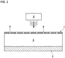
- a perforated plate 1 in an embodiment of the present invention is placed at a predetermined distance from a plate-shaped or wall-shaped closing member 2 so that an air layer 3 is formed between the perforated plate 1 and the closing member 2.
- the air layer 3 communicates with the outside only through a large number of through-holes 4 of the perforated plate 1. That is, ends of the perforated plate 1 are, for example, connected to the closing member 2, and they are closed by plates having no through-holes or the like.
- the closing member 2 is a member where no holes are made, that is, a front surface thereof does not communicate with a back surface thereof. In addition, the closing member 2 is placed on the opposite side to a noise source 5 across the perforated plate 1.
- Examples of materials of the perforated plate 1 and the closing member 2 may include aluminum, aluminum alloys, stainless steel, iron, resin, etc.
- FIG. 2 is an enlarged view of a part of a through-hole 4 in the perforated plate 1 shown in FIG. 1 .
- the through-hole 4 has a largest hole diameter portion 11 formed in one surface S1 of the perforated plate 1, and a smallest hole diameter portion 12 formed in the other surface S2. That is, the through-hole 4 is a through-hole whose diameter is different between the front surface and the back surface of the perforated plate 1, and reaches a maximum (Dmax) and a minimum (Dmin) respectively in the front and back surfaces of the hole.
- the Dmin (smallest hole diameter) is equal to or smaller than plate thickness t of the perforated plate 1.
- the smallest value of the Dmin is 0.01 mm.
- the hole diameter 0.01 mm is a diameter in which the sound absorbability cannot be improved more due to influence of overdamping. That is, the Dmin (smallest hole diameter) is 0.01 mm or more and equal to or smaller than the plate thickness t.
- the Dmax (largest hole diameter) is a larger diameter than the Dmin (smallest hole diameter), and is smaller than 1/2 of a hole pitch.
- the hole pitch is a distance between centers of adjacent holes.
- FIG. 2 which is a sectional view in the direction of the plate thickness t of the perforated plate 1
- the wall surface of the through-hole 4 between the largest hole diameter portion 11 and the smallest hole diameter portion 12 is put on a radially outer side from a straight line L connecting the largest hole diameter portion 11 and the smallest hole diameter portion 12, that is, a straight line L connecting one edge part of the largest hole diameter portion 11 and one edge part of the smallest hole diameter portion 12 on the same side as the edge part of the largest hole diameter portion 11. That is, the through-hole 4 has a shape swelling on a radially outer side from the straight line L.
- the through-hole 4 has a sectional area which is fixed or reduced as approaching the other surface S2 of the perforated plate 1 where the smallest hole diameter portion 12 is formed, from the one surface S1 of the perforated plate 1 where the largest hole diameter portion 11 is formed.
- the sectional area is fixed (the largest sectional area is kept) between the largest hole diameter portion 11 and a wall surface position 13 under the largest hole diameter portion 11, and then reduced gradually and continuously toward the other surface S2.
- plate thickness ta2 is smaller than plate thickness ta1 (ta2 ⁇ ta1) as shown in FIG. 2 , when ta1 designates a plate thickness at a middle point of a through-hole and ta2 designates a plate thickness where the hole diameter is the same as that at the middle point of the plate thickness ta1.
- the thickness in the plate thickness direction is smaller than that in the hole shown by the straight line L, which does not swell outward, when the two parts of the through-hole are compared at the same hole diameter.
- a position in the direction of the plate thickness t having the same hole diameter as that in the hole shown by the straight line L is disposed on the smallest diameter side.
- the wall surface of the hole may be formed by a curve at most parts of the through-hole 4.
- the wall surface of the hole may be formed by a combination of straight lines extending in an up/down direction, in an oblique direction and in a lateral direction (or the sectional area may be discontinuously reduced as going from the surface S1 toward the surface S2). That is, it will go well if the through-hole 4 has a sectional area being same or reduced as going from the surface S 1 toward the surface S2.
- the wall surface of the through-hole 4 may be formed by a combination of straight lines and curves, or may be formed by a combination of only curves (including a combination of curves having different curvatures), or may be formed by a combination of only straight lines.
- a larger hole diameter (sectional area) side may be disposed on the noise source 5 side, or on the contrary, of the through-hole 4, a smaller hole diameter (sectional area) side may be disposed on the noise source 5 side.
- a sound absorbing effect is determined by a pressure loss generated when a sound wave passes through the hole. The pressure loss is determined by the smallest part of the hole. Therefore, a similar sound absorbing effect can be obtained regardless of whether the smaller hole diameter side or the larger hole diameter side is disposed on the noise source 5 side.
- FIG. 3 is a graph showing a relation between the flow resistance and the frequency.
- the flow resistance Rt when the plate thickness is large, the flow resistance Rt is larger than the case where the plate thickness is small.
- the opening ratio ⁇ number of holes
- the thickness in the plate thickness direction at any part of the through-hole 4 is smaller than that in a through-hole having a sectional shape formed by a straight line, when the two parts of the through-hole are compared at parts having the same hole diameter as each other.
- the same effect as the case where the plate thickness of the perforated plate is reduced can be obtained.
- a part having great contribution to obtaining the same effect as that when the plate thickness of the perforated plate is reduced is a hole lower part B of the through-hole 4, which is a peripheral part of the smallest hole diameter portion 12 in the through-hole 4.
- the hole swells outside the straight line L at the hole lower part B (when the hole is formed into a curve like a concave (or may be formed by a straight line))
- the plate thickness can be easily reduced at any part of the through-hole 4 from the surface S1 to the surface S2.
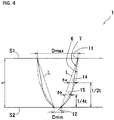
- FIG. 4 shows two embodiments of through-holes.
- a largest swelling position (a position of a largest swelling amount ⁇ a in a direction parallel to the surfaces S1 and S2 of the perforated plate 1) is preferably a central position in the direction of the plate thickness t of the perforated plate 1, or a position on the smallest hole diameter portion 12 side from the central position.
- a largest swelling position 14 of the through-hole 6 is set at the central position in the direction of the plate thickness t of the perforated plate 1.
- a largest swelling position 15 of the through-hole 7 (a position of a largest swelling amount ⁇ b in a direction parallel to the surfaces S1 and S2 of the perforated plate 1) is set on the smallest hole diameter portion 12 side from the central position in the direction of the plate thickness t and at a position of 1/4 ⁇ t from the surface S2 on the smallest hole diameter portion 12 side.
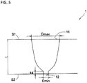
- the smallest hole diameter portion 12 has a certain thickness.
- the thickness td of the smallest hole diameter portion 12 is set at a predetermined thickness equal to or smaller than the hole diameter Dmin of the smallest hole diameter portion 12.
- FIG. 6 is a graph showing a comparison result of sound absorbability between the through-hole 7 shown in FIG. 4 and a through-hole having no swelling in the comparative example (a conical through-hole in which the largest hole diameter portion 11 and the smallest hole diameter portion 12 are connected by the straight line L in sectional view).
- a line indicated as "present invention” designates the through-hole 7 shown in FIG. 4 (an example of the embodiment).
- the opening ratio in the perforated plate having each through-hole was equally set at 0.5%. As is found from FIG.
- the sound absorbability can be improved on a larger scale in the through-hole 7 (the perforated plate 1 having a large number of through-holes 7) in the present invention than the case in the through-hole (the perforated plate having through-holes having no swelling) in the comparative example.
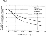
- FIG. 7 is a graph showing a comparison result as to the number of holes having the same sound absorbability between each through-holes 6 and 7 shown in FIG. 4 and the through-hole having no swelling in the comparative example (the conical through-hole in which the largest hole diameter portion 11 and the smallest hole diameter portion 12 are connected by the straight line L in sectional view).
- the ordinate in the graph shown in FIG. 7 designates the ratio of the number of through-holes 6 and 7 in the present invention (the perforated plate 1 having a large number of through-holes 6 or 7) when the number of holes in the through-hole having no swelling in the comparative example (the perforated plate having through-holes having no swelling) is taken as 100%.
- the abscissa in the graph designates the swelling amount at the largest swelling positions 14 and 15 of each of the through-holes 6 and 7.
- the number of through-holes 6 and 7 in the present invention (the perforated plate 1 having a large number of through-holes 6 or 7) can be reduced in comparison with the number of through-holes having no swelling in the comparative example (the perforated plate having through-holes having no swelling), in order to attain the same sound absorbability.
- the number of holes can be reduced in the case of the through-hole 7 in order to attain the same sound absorbability. That is, as the largest swelling position is made closer to the smallest hole diameter portion 12, the number of holes can be reduced.
- Each through-hole in a perforated plate in the present invention includes a largest hole diameter portion that is formed in one surface of the perforated plate, and a smallest hole diameter portion that is formed in the other surface of the perforated plate.
- the through-hole swells outside a straight line connecting the largest hole diameter portion and the smallest hole diameter portion.
- the thickness in the plate thickness direction at any part of the through-hole in the perforated plate can be made smaller than that in a case where the sectional shape of a through-hole is formed by a straight line, when the two parts of the through-hole are compared at places with the same diameter. In this manner, the same effect as that when the plate thickness of the perforated plate is reduced can be obtained. Thus, it is possible to obtain high sound absorbability with a small number of through-holes.
- a largest swelling position is a central position in the plate thickness direction of the perforated plate or a position on the smallest hole diameter portion side from the central position. In this configuration, it is possible to obtain high sound absorbability with a smaller number of through-holes.
- the smallest hole diameter portion has a thickness equal to or smaller than the hole diameter of the smallest hole diameter portion. In this configuration, it is possible to ensure satisfactory strength near the smallest hole diameter portion. In addition, it is also possible to obtain an effect of making it easier to machine the hole than the case where the smallest hole diameter portion is made to have a sharp structure.
Landscapes
- Physics & Mathematics (AREA)
- Engineering & Computer Science (AREA)
- Acoustics & Sound (AREA)
- Multimedia (AREA)
- Soundproofing, Sound Blocking, And Sound Damping (AREA)
- Vehicle Interior And Exterior Ornaments, Soundproofing, And Insulation (AREA)
- Superstructure Of Vehicle (AREA)
- Building Environments (AREA)
Abstract
Description
- The present invention relates to a perforated plate.
- For example,
Patent Literature 1 discloses a technique about a perforated plate as a sound-insulating material for a vehicle or the like. In a perforated sound-absorbing structure disclosed inPatent Literature 1, reinforcement plate materials each having a large number of through-holes are attached to surfaces of an outer material and an inner material on the side of a hollow portion respectively so as to form an air layer between those surfaces. Sound absorbability can be imparted to the inside of the hollow portion due to the reinforcement plate materials having a large number of through-holes. In the perforated sound-absorbing structure, a frequency range of high sound-absorptivity can be widened easily without attaching a fibrous sound-absorbing material to a lower surface of the inner material. - Patent Literature 1:
JP-A-2014-48632 - In
Patent Literature 1, there is no direct suggestion about specific detailed shapes of through-holes formed in each reinforcement plate material. As for a method for perforating the reinforcement plate material, punching is referred to in Paragraph 0054 ofPatent Literature 1. A hole made by punching is formed as a hole having a columnar shape whose sectional area is same from the front surface to back surface of the plate material. That is, it can be said thatPatent Literature 1 discloses a perforated plate having a large number of holes having columnar shapes each having the same sectional area from the front surface to back surface of the plate material. - When a perforated plate is used as a sound-insulating material for a vehicle or the like, it is preferable that the number of through-holes formed in the perforated plate is reduced regardless of whether the perforated plate is used as a reinforcement plate or not. When a large number of through-holes are made in the plate, strength of the plate deteriorates. On the other hand, when the number of through-holes is simply reduced, sound absorbability deteriorates. In addition, when the number of through-holes is increased, there arises another problem that the perforating cost is increased. Further, when the number of through-holes is increased excessively, there arises another problem that through-holes adjacent to each other interfere with each other.
- The present invention has been made in consideration of the aforementioned situation. An object of the present invention is to provide a perforated plate capable of obtaining high sound absorbability with a smaller number of through-holes than that of the through-holes in conventional cases.
- In the present invention, provided is a perforated plate including a large number of through-holes, the perforated plate being placed so that an air layer can be formed between the perforated plate and a plate-shaped or wall-shaped closing member. The through-hole includes a largest hole diameter portion that is formed in one surface of the perforated plate, and a smallest hole diameter portion that is formed in the other surface of the perforated plate; and in a sectional view in a plate thickness direction of the perforated plate, the through-hole swells outside a straight line connecting the largest hole diameter portion and the smallest hole diameter portion.
- Each through-hole is formed into a shape swelling outside a straight line connecting a largest hole diameter portion and a smallest hole diameter portion. Thus, thickness in any part of the through-hole in a plate thickness direction (which is a direction in which sound waves pass) affecting propagation of the sound waves can be made smaller than the case where the sectional shape of each hole is formed by a straight line. That is, in the shape of the through-hole in the present invention, thickness in any part of the through-hole in the plate thickness direction is smaller than that in a through-hole whose sectional shape is formed by a straight line, when the two through-holes are compared with each other at the parts having the same hole diameter. It is therefore possible to obtain high sound absorbability in spite of a reduced number of through-holes.
-
- [
FIG. 1 ] A sectional view showing a perforated sound-absorbing structure including a perforated plate in an embodiment of the present invention. - [
FIG. 2 ] An enlarged view of a part of a through-hole in the perforated plate shown inFIG. 1 . - [
FIG. 3 ] A graph showing a relation between flow resistance of the perforated plate and a frequency of a sound wave. - [
FIG. 4 ] A sectional view showing two embodiments of through-holes in the perforated plate. - [
FIG. 5 ] A sectional view showing an embodiment of a through-hole in the perforated plate. - [
FIG. 6 ] A graph showing a comparison result as to sound absorbability between a through-hole 7 shown inFIG. 4 and a through-hole having no swelling in the comparative example. - [
FIG. 7 ] A graph showing a comparison result as to the number of holes having the same sound absorbability between each of the through-holes FIG. 4 and the through-hole having no swelling in the comparative example. - Embodiments of the present invention will be described below with reference to the drawings.
- As shown in
FIG. 1 , aperforated plate 1 in an embodiment of the present invention is placed at a predetermined distance from a plate-shaped or wall-shaped closing member 2 so that anair layer 3 is formed between theperforated plate 1 and theclosing member 2. Theair layer 3 communicates with the outside only through a large number of through-holes 4 of theperforated plate 1. That is, ends of theperforated plate 1 are, for example, connected to theclosing member 2, and they are closed by plates having no through-holes or the like. - The
closing member 2 is a member where no holes are made, that is, a front surface thereof does not communicate with a back surface thereof. In addition, theclosing member 2 is placed on the opposite side to anoise source 5 across theperforated plate 1. - Examples of materials of the
perforated plate 1 and theclosing member 2 may include aluminum, aluminum alloys, stainless steel, iron, resin, etc. -
FIG. 2 is an enlarged view of a part of a through-hole 4 in theperforated plate 1 shown inFIG. 1 . As shown inFIG. 2 , the through-hole 4 has a largesthole diameter portion 11 formed in one surface S1 of theperforated plate 1, and a smallesthole diameter portion 12 formed in the other surface S2. That is, the through-hole 4 is a through-hole whose diameter is different between the front surface and the back surface of theperforated plate 1, and reaches a maximum (Dmax) and a minimum (Dmin) respectively in the front and back surfaces of the hole. - The Dmin (smallest hole diameter) is equal to or smaller than plate thickness t of the
perforated plate 1. The smallest value of the Dmin is 0.01 mm. The hole diameter 0.01 mm is a diameter in which the sound absorbability cannot be improved more due to influence of overdamping. That is, the Dmin (smallest hole diameter) is 0.01 mm or more and equal to or smaller than the plate thickness t. - The Dmax (largest hole diameter) is a larger diameter than the Dmin (smallest hole diameter), and is smaller than 1/2 of a hole pitch. The hole pitch is a distance between centers of adjacent holes.
- As shown in
FIG. 2 which is a sectional view in the direction of the plate thickness t of theperforated plate 1, the wall surface of the through-hole 4 between the largesthole diameter portion 11 and the smallesthole diameter portion 12 is put on a radially outer side from a straight line L connecting the largesthole diameter portion 11 and the smallesthole diameter portion 12, that is, a straight line L connecting one edge part of the largesthole diameter portion 11 and one edge part of the smallesthole diameter portion 12 on the same side as the edge part of the largesthole diameter portion 11. That is, the through-hole 4 has a shape swelling on a radially outer side from the straight line L. In addition, the through-hole 4 has a sectional area which is fixed or reduced as approaching the other surface S2 of theperforated plate 1 where the smallesthole diameter portion 12 is formed, from the one surface S1 of theperforated plate 1 where the largesthole diameter portion 11 is formed. In the embodiment shown inFIG. 2 , the sectional area is fixed (the largest sectional area is kept) between the largesthole diameter portion 11 and awall surface position 13 under the largesthole diameter portion 11, and then reduced gradually and continuously toward the other surface S2. - In the sectional view in the direction of the plate thickness t of the
perforated plate 1, it is the most essential that the through-hole 4 has a shape swelling outside the straight line L connecting the largesthole diameter portion 11 and the smallesthole diameter portion 12. In this configuration, plate thickness ta2 is smaller than plate thickness ta1 (ta2<ta1) as shown inFIG. 2 , when ta1 designates a plate thickness at a middle point of a through-hole and ta2 designates a plate thickness where the hole diameter is the same as that at the middle point of the plate thickness ta1. In this manner, at any part of the through-hole 4 in theperforated plate 1, the thickness in the plate thickness direction is smaller than that in the hole shown by the straight line L, which does not swell outward, when the two parts of the through-hole are compared at the same hole diameter. To say other words, at any part excluding the both end parts of the hole in the direction of the plate thickness t, a position in the direction of the plate thickness t having the same hole diameter as that in the hole shown by the straight line L is disposed on the smallest diameter side. - In the sectional view in the direction of the plate thickness t of the
perforated plate 1, the wall surface of the hole may be formed by a curve at most parts of the through-hole 4. However, the wall surface of the hole may be formed by a combination of straight lines extending in an up/down direction, in an oblique direction and in a lateral direction (or the sectional area may be discontinuously reduced as going from the surface S1 toward the surface S2). That is, it will go well if the through-hole 4 has a sectional area being same or reduced as going from thesurface S 1 toward the surface S2. In the sectional view in the direction of the plate thickness t of theperforated plate 1, the wall surface of the through-hole 4 may be formed by a combination of straight lines and curves, or may be formed by a combination of only curves (including a combination of curves having different curvatures), or may be formed by a combination of only straight lines. - As shown in
FIG. 1 , of the through-hole 4, a larger hole diameter (sectional area) side may be disposed on thenoise source 5 side, or on the contrary, of the through-hole 4, a smaller hole diameter (sectional area) side may be disposed on thenoise source 5 side. This reason will be described below. A sound absorbing effect is determined by a pressure loss generated when a sound wave passes through the hole. The pressure loss is determined by the smallest part of the hole. Therefore, a similar sound absorbing effect can be obtained regardless of whether the smaller hole diameter side or the larger hole diameter side is disposed on thenoise source 5 side. - (Reason why thickness in the plate thickness direction at any part of the through-
hole 4 is smaller than that in the case of a through-hole having a sectional shape formed by a straight line when the two parts of the through-hole are taken to have the same hole diameter) - Flow resistance (front and back pressure loss/passing flow rate) in a perforated plate having a large number of through-holes having a columnar shape with the same sectional area from its front surface to its back surface is expressed by the following formula (1).
[Formula 1]
-
- Rt: flow resistance
- η0: viscous resistance of air
- β: opening ratio of perforated plate
- d: hole diameter
- t: plate thickness of perforated plate
- po: density of air
- ω: angular velocity of sound wave (= frequency)
-
FIG. 3 is a graph showing a relation between the flow resistance and the frequency. As shown inFIG. 3 , when the plate thickness is large, the flow resistance Rt is larger than the case where the plate thickness is small. When the flow resistance Rt is large, it is necessary to increase the opening ratio β (number of holes) in the perforated plate to thereby reduce damping in order to obtain optimum damping. It is therefore necessary to increase the opening ratio β when the plate thickness is large. - As described above, when the through-
hole 4 is formed into a hole shape swelling outside the straight line L connecting the largesthole diameter portion 11 and the smallesthole diameter portion 12, the thickness in the plate thickness direction at any part of the through-hole 4 is smaller than that in a through-hole having a sectional shape formed by a straight line, when the two parts of the through-hole are compared at parts having the same hole diameter as each other. Thus, the same effect as the case where the plate thickness of the perforated plate is reduced can be obtained. As a result, it is possible to reduce the number of through-holes 4 for obtaining the same sound absorbability. In this manner, it is possible to obtain high sound absorbability with a reduced number of through-holes. Further, there are additional effects of reducing the cost in machining the hole, avoiding interference between adjacent through-holes, and improving strength of the perforated plate. - A part having great contribution to obtaining the same effect as that when the plate thickness of the perforated plate is reduced is a hole lower part B of the through-
hole 4, which is a peripheral part of the smallesthole diameter portion 12 in the through-hole 4. When the hole swells outside the straight line L at the hole lower part B (when the hole is formed into a curve like a concave (or may be formed by a straight line)), the plate thickness can be easily reduced at any part of the through-hole 4 from the surface S1 to the surface S2. -
FIG. 4 shows two embodiments of through-holes. In the sectional view in the direction of the plate thickness t of theperforated plate 1, of a part swelling outside the straight line L connecting the largesthole diameter portion 11 and the smallesthole diameter portion 12 in the through-hole, a largest swelling position (a position of a largest swelling amount δa in a direction parallel to the surfaces S1 and S2 of the perforated plate 1) is preferably a central position in the direction of the plate thickness t of theperforated plate 1, or a position on the smallesthole diameter portion 12 side from the central position. - As for a through-
hole 6 of two through-holes FIG. 4 , alargest swelling position 14 of the through-hole 6 is set at the central position in the direction of the plate thickness t of theperforated plate 1. As for the other through-hole 7, alargest swelling position 15 of the through-hole 7 (a position of a largest swelling amount δb in a direction parallel to the surfaces S1 and S2 of the perforated plate 1) is set on the smallesthole diameter portion 12 side from the central position in the direction of the plate thickness t and at a position of 1/4·t from the surface S2 on the smallesthole diameter portion 12 side. - As shown in
FIG. 5 , in order to ensure satisfactory strength near the smallesthole diameter portion 12, it is preferable to have a structure in which the smallesthole diameter portion 12 has a certain thickness. When the thickness of the smallesthole diameter portion 12 is larger than the hole diameter Dmin of the smallest hole diameter portion, the effect of improving the sound absorbing performance due to the hole shape of the through-hole swelling outside the straight line connecting the largest hole diameter portion and the smallest hole diameter portion is reduced. Therefore, the thickness td of the smallesthole diameter portion 12 is set at a predetermined thickness equal to or smaller than the hole diameter Dmin of the smallesthole diameter portion 12. - In this structure, it is possible to ensure satisfactory strength near the smallest
hole diameter portion 12 as described above. In addition, there is another effect that the hole can be machined more easily than when the smallesthole diameter portion 12 has a sharp structure. -
FIG. 6 is a graph showing a comparison result of sound absorbability between the through-hole 7 shown inFIG. 4 and a through-hole having no swelling in the comparative example (a conical through-hole in which the largesthole diameter portion 11 and the smallesthole diameter portion 12 are connected by the straight line L in sectional view). InFIG. 6 , a line indicated as "present invention" designates the through-hole 7 shown inFIG. 4 (an example of the embodiment). The opening ratio in the perforated plate having each through-hole was equally set at 0.5%. As is found fromFIG. 6 , the sound absorbability can be improved on a larger scale in the through-hole 7 (theperforated plate 1 having a large number of through-holes 7) in the present invention than the case in the through-hole (the perforated plate having through-holes having no swelling) in the comparative example. -
FIG. 7 is a graph showing a comparison result as to the number of holes having the same sound absorbability between each through-holes FIG. 4 and the through-hole having no swelling in the comparative example (the conical through-hole in which the largesthole diameter portion 11 and the smallesthole diameter portion 12 are connected by the straight line L in sectional view). - The ordinate in the graph shown in
FIG. 7 designates the ratio of the number of through-holes perforated plate 1 having a large number of through-holes 6 or 7) when the number of holes in the through-hole having no swelling in the comparative example (the perforated plate having through-holes having no swelling) is taken as 100%. The abscissa in the graph designates the swelling amount at the largest swelling positions 14 and 15 of each of the through-holes - As is found from
FIG. 7 , the number of through-holes perforated plate 1 having a large number of through-holes 6 or 7) can be reduced in comparison with the number of through-holes having no swelling in the comparative example (the perforated plate having through-holes having no swelling), in order to attain the same sound absorbability. - When the case of the through-hole 6 (the largest swelling position is 1/2·t from the surface S2) is compared with the case of the through-hole 7 (the largest swelling position is 1/4·t from the surface S2), the number of holes can be reduced in the case of the through-
hole 7 in order to attain the same sound absorbability. That is, as the largest swelling position is made closer to the smallesthole diameter portion 12, the number of holes can be reduced. - Each through-hole in a perforated plate in the present invention includes a largest hole diameter portion that is formed in one surface of the perforated plate, and a smallest hole diameter portion that is formed in the other surface of the perforated plate. In the sectional view in the plate thickness direction of the perforated plate, the through-hole swells outside a straight line connecting the largest hole diameter portion and the smallest hole diameter portion.
- In this configuration, the thickness in the plate thickness direction at any part of the through-hole in the perforated plate can be made smaller than that in a case where the sectional shape of a through-hole is formed by a straight line, when the two parts of the through-hole are compared at places with the same diameter. In this manner, the same effect as that when the plate thickness of the perforated plate is reduced can be obtained. Thus, it is possible to obtain high sound absorbability with a small number of through-holes.
- In addition, in the sectional view in the plate thickness direction of the perforated plate in the present invention, it is preferable that, of the part of the through-hole swelling outside the straight line connecting the largest hole diameter portion and the smallest hole diameter portion, a largest swelling position is a central position in the plate thickness direction of the perforated plate or a position on the smallest hole diameter portion side from the central position. In this configuration, it is possible to obtain high sound absorbability with a smaller number of through-holes.
- In addition, in the present invention, it is preferable that the smallest hole diameter portion has a thickness equal to or smaller than the hole diameter of the smallest hole diameter portion. In this configuration, it is possible to ensure satisfactory strength near the smallest hole diameter portion. In addition, it is also possible to obtain an effect of making it easier to machine the hole than the case where the smallest hole diameter portion is made to have a sharp structure.
- The present application is based on a Japanese patent application No.
2015-101502 filed on May 19, 2015 -
- 1: Perforated plate
- 2: Closing member
- 3: Air layer
- 4: Through-hole
- 11: Largest hole diameter portion
- 12: Smallest hole diameter portion
- L: Straight line connecting the largest
hole diameter portion 11 and the smallesthole diameter portion 12 - S 1: One surface
- S2: Other surface
- t: Plate thickness
Claims (3)
- A perforated plate comprising a large number of through-holes, the perforated plate being placed so that an air layer is formed between the perforated plate and a plate-shaped or wall-shaped closing member; wherein:the through-hole includes a largest hole diameter portion that is formed in one surface of the perforated plate, and a smallest hole diameter portion that is formed in the other surface of the perforated plate; andin a sectional view in a plate thickness direction of the perforated plate, the through-hole swells outside a straight line connecting the largest hole diameter portion and the smallest hole diameter portion.
- The perforated plate according to claim 1, wherein:in the sectional view in the plate thickness direction of the perforated plate, of a part of the through-hole swelling outside the straight line, a largest swelling position is a central position in the plate thickness direction of the perforated plate or a position on the smallest hole diameter portion side from the central position.
- The perforated plate according to claim 1 or 2, wherein:the smallest hole diameter portion has a thickness equal to or smaller than a hole diameter of the smallest hole diameter portion.
Applications Claiming Priority (2)
| Application Number | Priority Date | Filing Date | Title |
|---|---|---|---|
| JP2015101502A JP6495094B2 (en) | 2015-05-19 | 2015-05-19 | Perforated plate |
| PCT/JP2016/063587 WO2016185907A1 (en) | 2015-05-19 | 2016-05-02 | Perforated plate |
Publications (3)
| Publication Number | Publication Date |
|---|---|
| EP3300073A1 true EP3300073A1 (en) | 2018-03-28 |
| EP3300073A4 EP3300073A4 (en) | 2019-01-09 |
| EP3300073B1 EP3300073B1 (en) | 2026-04-22 |
Family
ID=57320264
Family Applications (1)
| Application Number | Title | Priority Date | Filing Date |
|---|---|---|---|
| EP16796301.6A Active EP3300073B1 (en) | 2015-05-19 | 2016-05-02 | Perforated plate |
Country Status (4)
| Country | Link |
|---|---|
| EP (1) | EP3300073B1 (en) |
| JP (1) | JP6495094B2 (en) |
| CN (1) | CN107615375B (en) |
| WO (1) | WO2016185907A1 (en) |
Cited By (3)
| Publication number | Priority date | Publication date | Assignee | Title |
|---|---|---|---|---|
| GB2605371A (en) * | 2021-03-29 | 2022-10-05 | Bae Systems Plc | Acoustic absorbing structures |
| AT526400A1 (en) * | 2022-07-29 | 2024-02-15 | Admonter Holzindustrie Ag | Building plate |
| US12548540B2 (en) | 2021-03-29 | 2026-02-10 | Bae Systems Plc | Acoustic absorbing structures |
Families Citing this family (4)
| Publication number | Priority date | Publication date | Assignee | Title |
|---|---|---|---|---|
| WO2018200760A1 (en) * | 2017-04-26 | 2018-11-01 | Corning Incorporated | Micro-perforated glass laminates and methods of making the same |
| CN111133504A (en) * | 2017-09-25 | 2020-05-08 | 富士胶片株式会社 | soundproof structure |
| JP2021018357A (en) * | 2019-07-22 | 2021-02-15 | 株式会社デンソー | Sound absorption device |
| JP2021018356A (en) * | 2019-07-22 | 2021-02-15 | 株式会社デンソー | Sound absorption and agitation device |
Family Cites Families (15)
| Publication number | Priority date | Publication date | Assignee | Title |
|---|---|---|---|---|
| JPS5288301A (en) * | 1976-01-19 | 1977-07-23 | Hiroshi Kofujita | Surge direction transmissive device |
| JPH0823753B2 (en) * | 1986-04-24 | 1996-03-06 | 松下電工株式会社 | Silencer |
| US5504281A (en) * | 1994-01-21 | 1996-04-02 | Minnesota Mining And Manufacturing Company | Perforated acoustical attenuators |
| JP3149366B2 (en) * | 1996-10-14 | 2001-03-26 | ユニプレス株式会社 | Ventilated sound insulation wall structure |
| EP1408483A4 (en) * | 2001-06-21 | 2008-06-11 | Kobe Steel Ltd | Porous soundproof structural body and method of manufacturing the structural body |
| US6629929B1 (en) * | 2002-11-08 | 2003-10-07 | Koninklijke Philips Electronics N.V. | Method and apparatus for automatically setting the transmit aperture and apodization of an ultrasound transducer array |
| AT413406B (en) * | 2003-08-18 | 2006-02-15 | Holzindustrie Leitinger Ges M | SOUND ABSORBING ELEMENT |
| EP1742201A4 (en) * | 2004-04-30 | 2017-07-19 | Kabushiki Kaisha Kobe Seiko Sho | Porous sound absorbing structure |
| KR100645824B1 (en) * | 2005-06-14 | 2006-11-14 | 김영옥 | Sound absorption panel |
| JP2007291834A (en) * | 2006-03-31 | 2007-11-08 | Yamaha Corp | Sound absorbing panel and method of manufacturing sound absorbing panel |
| CN2896509Y (en) * | 2006-05-16 | 2007-05-02 | 启碁科技股份有限公司 | Ion gun silencer |
| KR100790221B1 (en) * | 2007-04-17 | 2008-01-02 | 임기태 | Resonance sound absorption structure molding and sound absorption structure |
| FR2927590B1 (en) * | 2008-02-19 | 2012-04-20 | Peugeot Citroen Automobiles Sa | ACOUSTIC SCREEN SYSTEM FOR MOTOR VEHICLE. |
| WO2009129139A2 (en) * | 2008-04-14 | 2009-10-22 | 3M Innovative Properties Company | Multilayer sound absorbing sheet |
| JP6190291B2 (en) * | 2014-03-06 | 2017-08-30 | 株式会社神戸製鋼所 | Sound absorption panel |
-
2015
- 2015-05-19 JP JP2015101502A patent/JP6495094B2/en active Active
-
2016
- 2016-05-02 EP EP16796301.6A patent/EP3300073B1/en active Active
- 2016-05-02 WO PCT/JP2016/063587 patent/WO2016185907A1/en not_active Ceased
- 2016-05-02 CN CN201680028712.1A patent/CN107615375B/en active Active
Cited By (5)
| Publication number | Priority date | Publication date | Assignee | Title |
|---|---|---|---|---|
| GB2605371A (en) * | 2021-03-29 | 2022-10-05 | Bae Systems Plc | Acoustic absorbing structures |
| GB2605371B (en) * | 2021-03-29 | 2025-02-05 | Bae Systems Plc | Acoustic absorbing structures |
| US12548540B2 (en) | 2021-03-29 | 2026-02-10 | Bae Systems Plc | Acoustic absorbing structures |
| AT526400A1 (en) * | 2022-07-29 | 2024-02-15 | Admonter Holzindustrie Ag | Building plate |
| AT526400B1 (en) * | 2022-07-29 | 2024-05-15 | Admonter Holzindustrie Ag | Building board |
Also Published As
| Publication number | Publication date |
|---|---|
| WO2016185907A1 (en) | 2016-11-24 |
| JP6495094B2 (en) | 2019-04-03 |
| JP2016218197A (en) | 2016-12-22 |
| CN107615375A (en) | 2018-01-19 |
| EP3300073B1 (en) | 2026-04-22 |
| CN107615375B (en) | 2020-09-22 |
| EP3300073A4 (en) | 2019-01-09 |
Similar Documents
| Publication | Publication Date | Title |
|---|---|---|
| EP3300073A1 (en) | Perforated plate | |
| EP1662480A1 (en) | Sound absorbing structure and method of producing the same | |
| DE112006002411B4 (en) | Double-wall structure | |
| EP2998164B1 (en) | Vehicle sound absorption structure | |
| EP3334650B1 (en) | Aircraft door arrangement with a noise reduced hollow space which can be covered by an aircraft door | |
| JP6190291B2 (en) | Sound absorption panel | |
| EP2103911B1 (en) | Flow measurement with ultrasound | |
| US11660928B2 (en) | Air conditioner | |
| CN112776995A (en) | Multifrequency absorbing acoustic panel for aircraft engine nacelle | |
| US20180306191A1 (en) | Supercharger inlet panels | |
| CN104584117B (en) | Porous sound-absorbing structure | |
| JP2005266399A (en) | Resonator type sound absorption structure | |
| CN107284207A (en) | For motor vehicle glass guide way of vehicle door | |
| CN109532433A (en) | A kind of automobile tail gate inserts stiffening plate | |
| US20180274542A1 (en) | Bearing plate noise damper | |
| JP2017227787A (en) | Sound absorbing sheet | |
| CN105235610B (en) | A kind of air-conditioning box muffler and air-conditioning box | |
| CN113978215B (en) | Static rigidity reinforcing structure of sheet metal in car door | |
| Sinha et al. | A high performance airfoil-profile deflector for open sunroof wind noise | |
| EP4151470B1 (en) | Bumper beam arrangement | |
| EP4733178A1 (en) | Vehicle rear portion structure | |
| JP4567372B2 (en) | Silencer | |
| CN215398940U (en) | Steering wheel reinforcing pipe beam and vehicle | |
| Best | Swept Collector Design for the HALO Wind Tunnel | |
| CN208915104U (en) | A water trough structure for a vehicle and a vehicle |
Legal Events
| Date | Code | Title | Description |
|---|---|---|---|
| STAA | Information on the status of an ep patent application or granted ep patent |
Free format text: STATUS: THE INTERNATIONAL PUBLICATION HAS BEEN MADE |
|
| PUAI | Public reference made under article 153(3) epc to a published international application that has entered the european phase |
Free format text: ORIGINAL CODE: 0009012 |
|
| STAA | Information on the status of an ep patent application or granted ep patent |
Free format text: STATUS: REQUEST FOR EXAMINATION WAS MADE |
|
| 17P | Request for examination filed |
Effective date: 20171116 |
|
| AK | Designated contracting states |
Kind code of ref document: A1 Designated state(s): AL AT BE BG CH CY CZ DE DK EE ES FI FR GB GR HR HU IE IS IT LI LT LU LV MC MK MT NL NO PL PT RO RS SE SI SK SM TR |
|
| AX | Request for extension of the european patent |
Extension state: BA ME |
|
| DAV | Request for validation of the european patent (deleted) | ||
| DAX | Request for extension of the european patent (deleted) | ||
| A4 | Supplementary search report drawn up and despatched |
Effective date: 20181206 |
|
| RIC1 | Information provided on ipc code assigned before grant |
Ipc: B60R 13/08 20060101ALI20181130BHEP Ipc: G10K 11/172 20060101AFI20181130BHEP |
|
| RIN1 | Information on inventor provided before grant (corrected) |
Inventor name: YAMAGIWA, ICHIRO Inventor name: YAMAGUCHI, ZENZO |
|
| STAA | Information on the status of an ep patent application or granted ep patent |
Free format text: STATUS: EXAMINATION IS IN PROGRESS |
|
| 17Q | First examination report despatched |
Effective date: 20200709 |
|
| GRAP | Despatch of communication of intention to grant a patent |
Free format text: ORIGINAL CODE: EPIDOSNIGR1 |
|
| STAA | Information on the status of an ep patent application or granted ep patent |
Free format text: STATUS: GRANT OF PATENT IS INTENDED |
|
| INTG | Intention to grant announced |
Effective date: 20251217 |
|
| P01 | Opt-out of the competence of the unified patent court (upc) registered |
Free format text: CASE NUMBER: UPC_APP_0002922_3300073/2026 Effective date: 20260128 |
|
| GRAS | Grant fee paid |
Free format text: ORIGINAL CODE: EPIDOSNIGR3 |
|
| GRAA | (expected) grant |
Free format text: ORIGINAL CODE: 0009210 |
|
| STAA | Information on the status of an ep patent application or granted ep patent |
Free format text: STATUS: THE PATENT HAS BEEN GRANTED |
|
| AK | Designated contracting states |
Kind code of ref document: B1 Designated state(s): AL AT BE BG CH CY CZ DE DK EE ES FI FR GB GR HR HU IE IS IT LI LT LU LV MC MK MT NL NO PL PT RO RS SE SI SK SM TR |
|
| REG | Reference to a national code |
Ref country code: CH Ref legal event code: F10 Free format text: ST27 STATUS EVENT CODE: U-0-0-F10-F00 (AS PROVIDED BY THE NATIONAL OFFICE) Effective date: 20260422 Ref country code: GB Ref legal event code: FG4D |