EP3300042A1 - A mobile terminal - Google Patents
A mobile terminal Download PDFInfo
- Publication number
- EP3300042A1 EP3300042A1 EP16817220.3A EP16817220A EP3300042A1 EP 3300042 A1 EP3300042 A1 EP 3300042A1 EP 16817220 A EP16817220 A EP 16817220A EP 3300042 A1 EP3300042 A1 EP 3300042A1
- Authority
- EP
- European Patent Office
- Prior art keywords
- alarm
- mobile terminal
- flip
- flop
- pin
- Prior art date
- Legal status (The legal status is an assumption and is not a legal conclusion. Google has not performed a legal analysis and makes no representation as to the accuracy of the status listed.)
- Granted
Links
Images



Classifications
-
- G—PHYSICS
- G07—CHECKING-DEVICES
- G07F—COIN-FREED OR LIKE APPARATUS
- G07F7/00—Mechanisms actuated by objects other than coins to free or to actuate vending, hiring, coin or paper currency dispensing or refunding apparatus
- G07F7/08—Mechanisms actuated by objects other than coins to free or to actuate vending, hiring, coin or paper currency dispensing or refunding apparatus by coded identity card or credit card or other personal identification means
-
- G—PHYSICS
- G06—COMPUTING OR CALCULATING; COUNTING
- G06Q—INFORMATION AND COMMUNICATION TECHNOLOGY [ICT] SPECIALLY ADAPTED FOR ADMINISTRATIVE, COMMERCIAL, FINANCIAL, MANAGERIAL OR SUPERVISORY PURPOSES; SYSTEMS OR METHODS SPECIALLY ADAPTED FOR ADMINISTRATIVE, COMMERCIAL, FINANCIAL, MANAGERIAL OR SUPERVISORY PURPOSES, NOT OTHERWISE PROVIDED FOR
- G06Q20/00—Payment architectures, schemes or protocols
- G06Q20/30—Payment architectures, schemes or protocols characterised by the use of specific devices or networks
- G06Q20/32—Payment architectures, schemes or protocols characterised by the use of specific devices or networks using wireless devices
- G06Q20/322—Aspects of commerce using mobile devices [M-devices]
- G06Q20/3227—Aspects of commerce using mobile devices [M-devices] using secure elements embedded in M-devices
-
- G—PHYSICS
- G06—COMPUTING OR CALCULATING; COUNTING
- G06Q—INFORMATION AND COMMUNICATION TECHNOLOGY [ICT] SPECIALLY ADAPTED FOR ADMINISTRATIVE, COMMERCIAL, FINANCIAL, MANAGERIAL OR SUPERVISORY PURPOSES; SYSTEMS OR METHODS SPECIALLY ADAPTED FOR ADMINISTRATIVE, COMMERCIAL, FINANCIAL, MANAGERIAL OR SUPERVISORY PURPOSES, NOT OTHERWISE PROVIDED FOR
- G06Q20/00—Payment architectures, schemes or protocols
- G06Q20/30—Payment architectures, schemes or protocols characterised by the use of specific devices or networks
- G06Q20/32—Payment architectures, schemes or protocols characterised by the use of specific devices or networks using wireless devices
- G06Q20/327—Short range or proximity payments by means of M-devices
- G06Q20/3278—RFID or NFC payments by means of M-devices
-
- H—ELECTRICITY
- H04—ELECTRIC COMMUNICATION TECHNIQUE
- H04W—WIRELESS COMMUNICATION NETWORKS
- H04W4/00—Services specially adapted for wireless communication networks; Facilities therefor
- H04W4/80—Services using short range communication, e.g. near-field communication [NFC], radio-frequency identification [RFID] or low energy communication
Definitions
- the present invention relates to the communications field, and in particular, to a mobile terminal.
- NFC Near Field Communication
- RFID Radio Frequency Identification
- interworking technology and integrates functions of an induction card reader and an induction card, and a point-to-point function into a single chip, so as to implement identification and data exchange with a compatible device within a short distance.
- An NFC-enabled mobile phone is a mobile phone with an NFC module. Many corresponding applications may be developed for the mobile phone with the NFC module.
- a card mode is an application mode of the NFC-enabled mobile phone. In the card mode, a device with an NFC function is simulated as a non-contact card, such as an entrance guard card, a bus pass, or a bank card. The card emulation mode is mainly used for non-contact mobile payment in malls, transportation, and the like.
- POS point of sale
- POS point of sale
- Embodiments of the present invention provide a mobile terminal, so as to improve security of an NFC module when the mobile terminal is in a power-off state.
- a first aspect of the embodiments of the present invention provides a mobile terminal, including a Near Field Communication NFC module, an alarm, a control circuit, and a battery, where the control circuit is connected to the NFC module and the alarm, and the mobile terminal is in a power-off state; the battery is configured to supply power to the NFC module, the alarm, and the control circuit; the NFC module is configured to perform a card swiping operation according to a received card swiping request, and generate an interrupt signal; the control circuit is configured to start the alarm according to the interrupt signal; and the alarm is configured to send an alarm signal.
- the control circuit includes a flip-flop and a switch chip, where the flip-flop is configured to output a first toggle signal according to the interrupt signal output by the NFC module, where the first toggle signal is used to indicate that an output status of the flip-flop is toggled; and the switch chip is configured to start the alarm according to the first toggle signal output by the flip-flop.
- control circuit is further configured to turn off the alarm.
- the control circuit further includes a counter, where the counter is connected to the flip-flop and the NFC module; and the counter is configured to: start counting according to the interrupt signal generated by the NFC module, stop counting when a count reaches a preset value, and generate a counting stop signal; the flip-flop is further configured to output a second toggle signal according to the counting stop signal generated by the counter, where the second toggle signal is used to indicate that the output status of the flip-flop is toggled; and the switch chip is further configured to turn off the alarm according to the second toggle signal output by the flip-flop.
- the flip-flop is a JK flip-flop.
- the JK flip-flop includes a J pin, a K pin, a Q pin, and a CP pin, where the J pin and the K pin are connected to a high level, the Q pin is connected to the switch chip, and the CP pin is connected to the NFC module.
- the switch chip is a single pole, double throw switch chip.
- the single pole, double throw switch chip includes a COM1 pin and a COM2 pin, where the COM1 pin is connected to a positive electrode of the alarm, and the COM2 pin is connected to a negative electrode of the alarm.
- the alarm is a motor.
- the alarm is a flash lamp or a tricolor light.
- the mobile terminal in the embodiments of the present invention includes the NFC module, the alarm, the control circuit, and the battery.
- the NFC module may perform the card swiping operation, and generate the interrupt signal.
- the control circuit starts the alarm according to the interrupt signal, and the alarm sends the alarm signal.
- the battery still outputs a voltage, and the output voltage can support normal running of the NFC module, the control circuit, and the alarm. Therefore, even if the mobile terminal is in the power-off state, the alarm can still be triggered by the control circuit and send an alarm. That is, in this solution, even if the mobile terminal is in the power-off state, the mobile terminal still sends an alarm upon NFC-enabled card swiping. In this case, a user can know in time about mistaken NFC-enabled card swiping, thereby preventing a greater loss.
- the embodiments of the present invention provide a mobile terminal, so as to send an alarm upon an NFC-enabled card swiping operation when the mobile terminal is in a power-off state, alert a user in time, and prevent a greater loss.
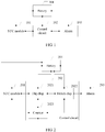
- an embodiment of a mobile terminal in the embodiments of the present invention includes an NFC module 101, a control circuit 102, an alarm 103, and a battery 104.
- the control circuit 102 is connected to the NFC module 101 and the alarm 103, and the mobile terminal is in a power-off state.
- the battery 104 is configured to supply power to the NFC module 101, the control circuit 102, and the alarm 103.
- the NFC module 101 is configured to perform a card swiping operation according to a received card swiping request, and generate an interrupt signal.
- the control circuit 102 is configured to start the alarm 103 according to the interrupt signal generated by the NFC module 101.
- the alarm 103 is configured to send an alarm signal.
- the card swiping operation herein is an operation that the mobile terminal is simulated as a non-contact card by using the NFC module and implements a corresponding function of the card, for example, an operation that the mobile terminal is simulated as a bus pass and swiped over a POS machine in a bus to pay from a balance of the bus pass, or an operation that the mobile terminal is simulated as an entrance guard card and swiped over a corresponding induction zone for access.
- the mobile terminal in this embodiment of the present invention includes the NFC module 101, the alarm 103, the control circuit 102, and the battery 104.
- the NFC module 101 may perform the card swiping operation, and generate the interrupt signal.
- the control circuit 102 starts the alarm 103 according to the interrupt signal, and the alarm 103 sends the alarm signal.
- the battery 104 still outputs a voltage, and the output voltage can support normal running of the NFC module 101, the control circuit 102, and the alarm 103. Therefore, even if the mobile terminal is in the power-off state, the alarm 103 can still be triggered by the control circuit 102 and send an alarm.
- FIG. 2 another embodiment of a mobile terminal in the embodiments of the present invention includes:
- the battery 204 is configured to supply power to the NFC module 201, the control circuit 202, and the alarm 203.
- the NFC module 201 is configured to perform a card swiping operation according to a received card swiping request, and generate an interrupt signal.
- the control circuit 202 is configured to start the alarm 203 according to the interrupt signal generated by the NFC module 201.
- the alarm 203 is configured to send an alarm signal.
- the control circuit 202 includes a flip-flop 2021 and a switch chip 2022.
- the flip-flop 2021 is configured to output a first toggle signal according to the interrupt signal output by the NFC module 201.
- the first toggle signal is used to indicate that an output status of the flip-flop 2021 is toggled.
- the switch chip 2022 is configured to start the alarm 203 according to the first toggle signal output by the flip-flop 2021.
- control circuit 202 may be further configured to turn off the alarm 203.
- control circuit 202 may include a counter 2023.
- the counter 2023 is configured to: start counting according to the interrupt signal generated by the NFC module, stop counting when a count reaches a preset value, and generate a counting stop signal.
- the flip-flop 2021 is further configured to output a second toggle signal according to the counting stop signal generated by the counter, where the second toggle signal is used to indicate that the output status of the flip-flop is toggled.
- the switch chip 2022 is further configured to turn off the alarm 203 according to the second toggle signal output by the flip-flop 2021.
- control circuit 202 may alternatively exclude the counter 2023. No specific limitation is imposed herein.
- the card swiping operation in this embodiment of the present invention is an operation that the mobile terminal is simulated as a non-contact card by using the NFC module and implements a corresponding function of the card, for example, an operation that the mobile terminal is simulated as a bus pass and swiped over a POS machine in a bus to pay from a balance of the bus pass, or an operation that the mobile terminal is simulated as an entrance guard card and swiped over a corresponding induction zone for access.
- the alarm in this embodiment of the present invention may be a motor, a flash lamp, a tricolor light, or another device that is in the mobile terminal and that is capable of sending an alarm signal. No specific limitation is imposed herein.
- the mobile terminal in this embodiment of the present invention includes the NFC module 201, the alarm 203, the control circuit 202, and the battery 204.
- the NFC module 201 may perform the card swiping operation, and generate the interrupt signal.
- the control circuit 202 starts the alarm 203 according to the interrupt signal, and the alarm 203 sends the alarm signal.
- the battery 204 still outputs a voltage, and the output voltage can support normal running of the NFC module 201, the control circuit 202, and the alarm 203. Therefore, even if the mobile terminal is in the power-off state, the alarm 203 can still be triggered by the control circuit 202 and send an alarm.
- this embodiment of the present invention provides a specific process of starting the alarm 203 by the control circuit 202. This improves implementability of the solution.
- control circuit 202 may include the counter 2023. According to the counter 2023, the control circuit 202 may turn off the alarm 203 after a preset time elapses. This increases flexibility of the solution and improves user experience.
- FIG. 3 another embodiment of a mobile terminal in the embodiments of the present invention includes an NFC module 301, a control circuit 302, an alarm 303, and a battery 304, and the mobile terminal is in a power-off state.
- the battery 304 is configured to supply power to the NFC module 301, the control circuit 302, and the alarm 303.
- the NFC module 301 is configured to perform a card swiping operation according to a received card swiping request, and generate an interrupt signal.
- the control circuit 302 is configured to start the alarm 103 according to the interrupt signal generated by the NFC module 301.
- the alarm 303 is configured to send an alarm signal.
- the control circuit 302 includes a JK flip-flop 3021 and a single pole, double throw switch chip 3022.
- the JK flip-flop 3021 includes a J pin, a K pin, a Q pin, and a CP pin.
- the J pin and the K pin are connected to a high level
- the Q pin is connected to the single pole, double throw switch chip
- the CP pin is connected to the NFC module 301.
- the JK flip-flop 3021 is configured to output a first toggle signal according to the interrupt signal generated by the NFC module, where the first toggle signal is used to indicate that an output status of the JK flip-flop is toggled.
- the single pole, double throw switch chip 3022 is configured to start the alarm according to the first toggle signal output by the JK flip-flop.
- the card swiping operation herein is an operation that the mobile terminal is simulated as a non-contact card by using the NFC module and implements a corresponding function of the card, for example, an operation that the mobile terminal is simulated as a bus pass and swiped over a POS machine in a bus to pay from a balance of the bus pass, or an operation that the mobile terminal is simulated as an entrance guard card and swiped over a corresponding induction zone for access.
- the JK flip-flop is a basic circuit unit in a digital circuit flip-flop.
- the JK flip-flop has functions of setting to 0, setting to 1, holding, and toggling. Which function the JK flip-flop performs is related to a level connected to the J pin and the K pin. In this embodiment of the present invention, both the J pin and the K pin are connected to a high level, so that the JK flip-flop performs the toggling function. Toggling means that a level output by the Q pin of the JK flip-flop changes from a low level to a high level or from a high level to a low level once a trigger signal is input.
- a function of a single pole, double throw switch may be to control a power supply to output in two different directions, that is, may be used for controlling two devices; or may be to control a same device to change an operation direction.
- the single pole, double throw switch chip is a chip capable of simulating the function of the single pole, double throw switch.
- a function of the single pole, double throw switch chip is to control a switch of the alarm. Specifically, a COM1 pin of the single pole, double throw switch is connected to a positive electrode of the alarm, a COM2 pin is connected to a negative electrode of the alarm, and connections of the other pins are shown in FIG. 2 .
- An initial state is that the COM1 pin is connected to an NC1 pin, and the COM2 pin is connected to an NC2 pin.
- a battery voltage is input to both the positive and the negative electrodes of the alarm, the alarm is not in a working state, and the alarm is turned off.
- an output level of the flip-flop is toggled, that is, when the first toggle signal is input to the single pole, double throw switch, a working status of the single pole, double throw switch chip is changed as follows:
- the COM1 pin is connected to an NO1 pin, and the COM2 pin is connected to an NO2 pin.
- the battery voltage is input to the positive electrode of the alarm, and the negative electrode of the alarm is grounded; the alarm forms a loop, and the alarm is started.
- FIG. 2 is merely an example of a connection of the single pole, double throw switch chip.
- the single pole, double throw switch chip may also control on and off of the alarm in another manner. No specific limitation is imposed herein.
- the alarm in this embodiment of the present invention may be a motor, a flash lamp, a tricolor light, or another device that is in the mobile terminal and that is capable of sending an alarm signal. No specific limitation is imposed herein.
- the mobile terminal in this embodiment of the present invention includes the NFC module 301, the alarm 303, the control circuit 302, and the battery 304.
- the NFC module 301 may perform the card swiping operation, and generate the interrupt signal.
- the control circuit 302 starts the alarm 303 according to the interrupt signal, and the alarm 303 sends the alarm signal.
- the battery 304 still outputs a voltage, and the output voltage can support normal running of the NFC module 301, the control circuit 302, and the alarm 303. Therefore, even if the mobile terminal is in the power-off state, the alarm 303 can still be triggered by the control circuit 302 and send an alarm.
- this embodiment of the present invention provides a specific implementation that the control circuit 302 starts the alarm 303 by using the JK flip-flop 3021 and the single pole, double throw switch chip 3022. This improves implementability of the solution.
- the battery 404 is configured to supply power to the NFC module 401, the control circuit 402, and the alarm 403.
- the NFC module 401 is configured to perform a card swiping operation according to a received card swiping request, and generate an interrupt signal.
- the control circuit 402 is configured to start the alarm 403 according to the interrupt signal generated by the NFC module 401.
- the alarm 403 is configured to send an alarm signal.
- the control circuit 402 includes a JK flip-flop 4021, a single pole, double throw switch chip 4022, and a counter 4023.
- the JK flip-flop 4021 includes a J pin, a K pin, a Q pin, and a CP pin.
- the J pin and the K pin are connected to a high level
- the Q pin is connected to the single pole, double throw switch chip
- the CP pin is connected to the NFC module 401.
- the counter 402 is connected to the CP pin of the JK flip-flop and the NFC module.
- the JK flip-flop 4021 is configured to output a first toggle signal according to the interrupt signal generated by the NFC module 401, and output a second toggle signal according to a counting stop signal generated by the counter 4023.
- the second toggle signal and the second toggle signal are used to indicate that an output signal of the JK flip-flop 4021is toggled.
- the single pole, double throw switch chip 4022 is configured to start the alarm according to the first toggle signal output by the JK flip-flop 4021, and turn off the alarm 403 according to the second toggle signal output by the JK flip-flop 4021.
- the counter 4023 is configured to: start counting according to the interrupt signal generated by the NFC module 401, stop counting when a count reaches a preset value, and generate a counting stop signal.
- the card swiping operation in this embodiment of the present invention is an operation that the mobile terminal is simulated as a non-contact card by using the NFC module and implements a corresponding function of the card, for example, an operation that the mobile terminal is simulated as a bus pass and swiped over a POS machine in a bus to pay from a balance of the bus pass, or an operation that the mobile terminal is simulated as an entrance guard card and swiped over a corresponding induction zone for access.
- the alarm in this embodiment of the present invention may be a motor, a flash lamp, a tricolor light, or another device that is in the mobile terminal and that is capable of sending an alarm signal. No specific limitation is imposed herein.
- the mobile terminal in this embodiment of the present invention includes the NFC module 401, the alarm 403, the control circuit 402, and the battery 404.
- the NFC module 401 may perform the card swiping operation, and generate the interrupt signal.
- the control circuit 402 starts the alarm 403 according to the interrupt signal, and the alarm 403 sends the alarm signal.
- the battery 404 still outputs a voltage, and the output voltage can support normal running of the NFC module 401, the control circuit 402, and the alarm 403. Therefore, even if the mobile terminal is in the power-off state, the alarm 403 can still be triggered by the control circuit 402 and send an alarm.
- this embodiment of the present invention provides a specific implementation that the control circuit 402 starts the alarm 403 according to the JK flip-flop 4021 and the single pole, double throw switch chip 4022, and a specific implementation that the control circuit 402 turns off the alarm 403 according to the counter 4023, the JK flip-flop 4021, and the single pole, double throw switch chip 4022. This improves implementability of the solution.
- a user A carries a bus POS machine
- a user B carries a mobile terminal.
- the mobile terminal is in the power-off state, and the mobile terminal includes a central processing unit CPU, a SIM card, the NFC module 401, the JK flip-flop 4021, the single pole, double throw switch chip 4022, the counter 4023, the alarm 403, and the battery 404.
- the battery 404 supplies power to components on the mobile terminal, and a bus pass function is enabled for the NFC module 401.
- a balance of the bus pass is 200 yuan.
- the J pin and the K pin of the JK flip-flop 4021 are connected to a high level, and the CP pin is connected to the NFC module 401 and the counter 4023.
- An NC1 pin and an NO2 pin of the single pole, double throw switch chip 4022 are connected to a battery voltage, an NC2 is connected to a load R2, the R2 is connected to the battery voltage, an IN1 pin and an IN2 pin are connected to the Q pin of the JK flip-flop 4021, a COM1 pin is connected to a positive electrode of the alarm 403, a COM2 pin is connected to a negative electrode of the alarm, and the NO2 is connected to a load R1.
- a CR pin of the counter 4023 is connected to the NFC module, and a CLK pin is connected to a 32.768 kHz crystal oscillator. Connection between the pins is shown in FIG. 3 .
- the user A approaches the user B, and a distance between the bus POS machine of the user A and the mobile terminal of the user B is 10 centimeters.
- the bus POS machine of the user A obtains 50 yuan from the balance of the bus pass by using the NFC module 401 on the mobile terminal of the user B.
- the NFC module 401 generates an interrupt signal, and the interrupt signal is input to the JK flip-flop 421 through the CP pin, that is, a rectangular pulse is input to the CP pin.
- a signal output by the Q pin of the JK flip-flop 4021 is toggled from an original low level to a high level.
- Such a toggle signal is the first toggle signal, and makes the single pole, double throw switch chip 4022 change a working status as follows:
- the COM1 pin is connected to an NO1 pin, and the COM2 pin is connected to the NO2 pin, so that the battery voltage is input to the positive electrode of the alarm 403 while the negative electrode of the alarm 403 is grounded, that is, the alarm 403 is started, and the alarm 403 sends an alarm signal.
- the interrupt signal is also input to the counter 4023 through the CR pin as an enable signal of the counter 4023, so as to make the counter 4023 start counting, and the counter 4023 starts to count from 1 to 60. After 60 seconds, the counter 4023 completes counting. The counter 4023 stops counting, and a counting stop signal is then generated.
- the counting stop signal is input to the JK flip-flop 4021 through the CP pin, that is, another rectangular pulse is input to the JK flip-flop 4021, and a signal output by the Q pin of the JK flip-flop 4021 is toggled again from the original high level to a low level.
- Such a toggle signal is the second toggle signal, and makes the single pole, double throw switch chip 4023 change the working status again as follows:
- the COM1 pin is connected to the NC1
- the COM2 pin is connected to the NC2 pin, so that the battery voltage is input to the positive and negative electrodes of the alarm 403, and the alarm 403 stops running, that is, the alarm 403 stops generating the alarm signal.
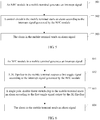
- an embodiment of a card swiping alerting method in the embodiments of the present invention includes the following steps.
- An NFC module in a mobile terminal generates an interrupt signal.
- the NFC module in the mobile terminal is started; and the NFC module performs a card swiping operation, and generates the interrupt signal.
- the card swiping operation herein is an operation that the mobile terminal is simulated as a non-contact card by using the NFC module and implements a corresponding function of the card, for example, an operation that the mobile terminal is simulated as a bus pass and swiped over a POS machine in a bus to pay from a balance of the bus pass, or an operation that the mobile terminal is simulated as an entrance guard card and swiped over a corresponding induction zone for access.
- a control circuit in the mobile terminal starts an alarm according to the interrupt signal generated by the NFC module.
- the interrupt signal is input to the control circuit in the mobile terminal, and the control circuit starts the alarm according to the interrupt signal.
- the alarm in the mobile terminal sends an alarm signal.
- the alarm in the mobile terminal sends the alarm signal.
- the mobile terminal is in the power-off state; when the NFC module in the mobile terminal performs the card swiping operation, the NFC module generates the interrupt signal; and the control circuit in the mobile terminal starts the alarm according to the interrupt signal, and the alarm sends the alarm signal. That is, even if in the power-off state, the mobile terminal can still send an alarm by using a hardware module, such as the control circuit, upon NFC-enabled card swiping. This allows a user to know in time about mistaken card swiping or card swiping performed by a thief and retrieve a loss in time, thereby preventing a greater loss.
- a hardware module such as the control circuit
- control circuit may start the alarm in different manners according to different compositions.
- the following describes in detail a specific process of starting an alarm by a control circuit.
- the control circuit includes a JK flip-flop and a single pole, double throw switch chip.
- FIG. 6 another embodiment of a card swiping alerting method in the embodiments of the present invention includes the following steps.
- An NFC module in a mobile terminal generates an interrupt signal.
- the NFC module in the mobile terminal is started; and the NFC module performs a card swiping operation, and generates the interrupt signal.
- the card swiping operation herein is an operation that the mobile terminal is simulated as a non-contact card by using the NFC module and implements a corresponding function of the card, for example, an operation that the mobile terminal is simulated as a bus pass and swiped over a POS machine in a bus to pay from a balance of the bus pass, or an operation that the mobile terminal is simulated as an entrance guard card and swiped over a corresponding induction zone for access.
- the JK flip-flop in the mobile terminal outputs a first toggle signal according to the interrupt signal generated by the NFC module.
- the interrupt signal is used as a trigger signal to trigger the JK flip-flop.
- the JK flip-flop is triggered, an output status is toggled and the first toggle signal is generated.
- the first toggle signal is input to the single pole, double throw switch chip.
- the single pole, double throw switch chip in the mobile terminal starts an alarm according to the first toggle signal output by the JK flip-flop.
- the single pole, double throw switch chip After the JK flip-flop in the mobile terminal inputs the first toggle signal to the single pole, double throw switch chip, the single pole, double throw switch chip changes a working status of the alarm according to the first toggle signal, and starts the alarm.
- the alarm in the mobile terminal sends an alarm signal.
- the alarm in the mobile terminal sends the alarm signal.
- the alarm may be a motor, a flash lamp, a tricolor light, or another device that is in the mobile terminal and that is capable of sending an alarm signal. No specific limitation is imposed herein.
- the alarm signal sent by the alarm may be vibration of the motor, flashing of the flash lamp, or blinking of the tricolor light.
- the mobile terminal may also send the alarm signal in another manner. No specific limitation is imposed herein.
- the mobile terminal is in the power-off state; when the NFC module in the mobile terminal performs the card swiping operation, the NFC module generates the interrupt signal; and the control circuit in the mobile terminal starts the alarm according to the interrupt signal, and the alarm sends the alarm signal. That is, even if in the power-off state, the mobile terminal can still send an alarm by using a hardware module, such as the control circuit, upon NFC-enabled card swiping. This allows a user to know in time about mistaken card swiping or card swiping performed by a thief and retrieve a loss in time, thereby preventing a greater loss.
- a hardware module such as the control circuit
- the control circuit may turn off the alarm in multiple manners.
- the following describes a manner of turning off an alarm in detail.
- the control circuit includes a JK flip-flop, a single pole, double throw switch, and a counter.
- FIG. 6 another embodiment of a card swiping alerting method in the embodiments of the present invention includes the following steps.
- An NFC module in a mobile terminal generates an interrupt signal.
- the NFC module in the mobile terminal is started; and the NFC module performs a card swiping operation, and generates the interrupt signal.
- the card swiping operation herein is an operation that the mobile terminal is simulated as a non-contact card by using the NFC module and implements a corresponding function of the card, for example, an operation that the mobile terminal is simulated as a bus pass and swiped over a POS machine in a bus to pay from a balance of the bus pass, or an operation that the mobile terminal is simulated as an entrance guard card and swiped over a corresponding induction zone for access.
- the JK flip-flop in the mobile terminal outputs a first toggle signal according to the interrupt signal generated by the NFC module.
- the interrupt signal is used as a trigger signal to trigger the JK flip-flop.
- the JK flip-flop is triggered, an output status is toggled and the first toggle signal is generated.
- the first toggle signal is input to the single pole, double throw switch chip.
- the counter in the mobile terminal starts counting according to the interrupt signal generated by the NFC module.
- the interrupt signal is input to the counter, and the counter starts counting according to the interrupt signal.
- the single pole, double throw switch chip in the mobile terminal starts an alarm according to the first toggle signal output by the JK flip-flop.
- the single pole, double throw switch chip After the JK flip-flop in the mobile terminal inputs the first toggle signal to the single pole, double throw switch chip, the single pole, double throw switch chip changes a working status of the alarm according to the first toggle signal, and starts the alarm.
- the alarm in the mobile terminal sends an alarm signal.
- the alarm in the mobile terminal sends the alarm signal.
- the alarm may be a motor, a flash lamp, a tricolor light, or another device that is in the mobile terminal and that is capable of sending an alarm signal. No specific limitation is imposed herein.
- the alarm signal sent by the alarm may be vibration of the motor, flashing of the flash lamp, or blinking of the tricolor light.
- the mobile terminal may also send the alarm signal in another manner. No specific limitation is imposed herein.
- the counter in the mobile terminal stops counting, and generates a counting stop signal.
- the JK flip-flop in the mobile terminal outputs a second toggle signal according to the counting stop signal.
- the counting stop signal is used as another trigger signal to trigger the JK flip-flop again.
- the JK flip-flop is triggered, an output status is toggled again and the second toggle signal is generated.
- the second toggle signal is input to the single pole, double throw switch chip.
- the single pole, double throw switch in the mobile terminal turns off the alarm according to the second toggle signal.
- the single pole, double throw switch changes the working status of the alarm again according to the second toggle signal, and turns off the alarm, so that the alarm stops sending the alarm signal.
- the mobile terminal is in the power-off state; when the NFC module in the mobile terminal performs the card swiping operation, the NFC module generates the interrupt signal; and the control circuit in the mobile terminal starts the alarm according to the interrupt signal, and the alarm sends the alarm signal. That is, even if in the power-off state, the mobile terminal can still send an alarm by using a hardware module, such as the control circuit, upon NFC-enabled card swiping. This allows a user to know in time about mistaken card swiping or card swiping performed by a thief and retrieve a loss in time, thereby preventing a greater loss.
- a hardware module such as the control circuit
- control circuit further includes the counter.
- the counter may start counting according to the interrupt signal, and when the count reaches the preset value, stop counting and generate a counting stop signal.
- the JK flip-flop outputs the second toggle signal according to the counting stop signal, so that the single pole, double throw switch chip turns off the alarm according to the second toggle signal. That is, a user may set a value of the counter, so as to turn off the alarm after the preset duration is reached. This improves user experience.
- a user A carries a bus POS machine
- a user B carries a mobile phone.
- the mobile phone is in a power-off state, and the mobile phone includes a central processing unit CPU, a SIM card, an NFC module, a JK flip-flop, a single pole, double throw switch chip, a counter, and a motor.
- a bus pass function is enabled for the NFC module, and a balance of the bus pass is 200 yuan.
- the user A approaches the user B, and a distance between the bus POS machine of the user A and the mobile phone of the user B is 10 centimeters.
- the bus POS machine of the user A obtains 50 yuan from the balance of the bus pass by using the NFC module on the mobile phone of the user B.
- the NFC module generates an interrupt signal, and the interrupt signal is input to both the JK flip-flop and the counter.
- the interrupt signal enables an output status of the JK flip-flop to be toggled, and a first toggle signal is input to the single pole, double throw switch chip.
- the first toggle signal makes the single pole, double throw switch chip change a working status of the motor, and the motor switches from a vibration stop state to a vibration state, so that the mobile phone vibrates.
- the interrupt signal is input to the counter, the counter starts counting from 1 to 60.
- the counter completes counting and stops counting, and a counting stop signal is then generated.
- the counting stop signal is input to the JK flip-flop, so that the output status of the JK flip-flop is toggled again and a second toggle signal is input to the single pole, double throw switch chip.
- the second toggle signal makes the single pole, double throw switch chip change the working status of the motor again, and the motor switches from the vibration state to the vibration stop state, so that the mobile phone stops vibrating.
- the disclosed system, apparatus, and method may be implemented in other manners.
- the described apparatus embodiment is merely an example.
- the unit division is merely logical function division and may be other division in actual implementation.
- multiple units or components may be combined or may be integrated into another system, or some features may be ignored or not performed.
- the displayed or discussed mutual couplings or direct couplings or communication connections may be implemented by using some interfaces.
- the indirect couplings or communication connections between the apparatuses or units may be implemented in electronic, mechanical, or other forms.
- the units described as separate parts may or may not be physically separate, and parts displayed as units may or may not be physical units, may be located in one position, or may be distributed on a plurality of network units. Some or all of the units may be selected according to actual requirements to achieve the objectives of the solutions of the embodiments.
- functional units in the embodiments of the present invention may be integrated into one processing unit, or each of the units may exist alone physically, or two or more units may be integrated into one unit.
- the integrated unit may be implemented in a form of hardware, or may be implemented in a form of a software functional unit.
- the integrated unit When the integrated unit is implemented in the form of a software functional unit and sold or used as an independent product, the integrated unit may be stored in a computer-readable storage medium. Based on such an understanding, the technical solutions of the present invention essentially, or the part contributing to the prior art, or all or some of the technical solutions may be implemented in the form of a software product.
- the software product is stored in a storage medium and includes several instructions for instructing a computer device (which may be a personal computer, a server, a network device, or the like) to perform all or some of the steps of the methods described in the embodiments of the present invention.
- the foregoing storage medium includes: any medium that can store program code, such as a USB flash drive, a removable hard disk, a read-only memory (ROM, Read-Only Memory), a random access memory (RAM, Random Access Memory), a magnetic disk, or an optical disc.
- program code such as a USB flash drive, a removable hard disk, a read-only memory (ROM, Read-Only Memory), a random access memory (RAM, Random Access Memory), a magnetic disk, or an optical disc.
Landscapes
- Engineering & Computer Science (AREA)
- Business, Economics & Management (AREA)
- Physics & Mathematics (AREA)
- General Physics & Mathematics (AREA)
- Computer Networks & Wireless Communication (AREA)
- Accounting & Taxation (AREA)
- Strategic Management (AREA)
- General Business, Economics & Management (AREA)
- Theoretical Computer Science (AREA)
- Telephone Function (AREA)
Abstract
Description
- This application claims priority to Chinese Patent Application No.
201510377689.4 - The present invention relates to the communications field, and in particular, to a mobile terminal.
- A Near Field Communication (NFC, Near Field Communication) technology evolves out of combination of a non-contact radio frequency identification (RFID, Radio Frequency Identification) technology and an interworking technology, and integrates functions of an induction card reader and an induction card, and a point-to-point function into a single chip, so as to implement identification and data exchange with a compatible device within a short distance.
- To facilitate shopping and consumption in daily life, an increasing quantity of terminal products now have integrated an NFC function. Operators China Mobile and China Unicorn have released corresponding NFC-enabled mobile phones, and China Telecom will also launch mobile phone terminals with an NFC function.
- An NFC-enabled mobile phone is a mobile phone with an NFC module. Many corresponding applications may be developed for the mobile phone with the NFC module. A card mode is an application mode of the NFC-enabled mobile phone. In the card mode, a device with an NFC function is simulated as a non-contact card, such as an entrance guard card, a bus pass, or a bank card. The card emulation mode is mainly used for non-contact mobile payment in malls, transportation, and the like. During shopping and consumption, people can conveniently and efficiently make a payment by using an NFC module of a mobile phone. A user simply brings a mobile phone near a point of sale (POS, point of sale) machine, and enters a password to confirm a transaction or directly accept a transaction. In this manner, power is supplied to the card by a non-contact card reader, and the card can still work even if the NFC-enabled mobile phone is out of power.
- However, when a mobile phone is powered off, if a thief brings a portable POS machine near the mobile phone, an NFC function of the mobile phone can still be enabled for swiping to obtain an account balance, consequently causing a loss to a user.
- Embodiments of the present invention provide a mobile terminal, so as to improve security of an NFC module when the mobile terminal is in a power-off state.
- In view of this, a first aspect of the embodiments of the present invention provides a mobile terminal, including a Near Field Communication NFC module, an alarm, a control circuit, and a battery, where the control circuit is connected to the NFC module and the alarm, and the mobile terminal is in a power-off state;
the battery is configured to supply power to the NFC module, the alarm, and the control circuit;
the NFC module is configured to perform a card swiping operation according to a received card swiping request, and generate an interrupt signal;
the control circuit is configured to start the alarm according to the interrupt signal; and
the alarm is configured to send an alarm signal. - With reference to the first aspect of the present invention, in a first implementation of the first aspect of the present invention, the control circuit includes a flip-flop and a switch chip, where
the flip-flop is configured to output a first toggle signal according to the interrupt signal output by the NFC module, where the first toggle signal is used to indicate that an output status of the flip-flop is toggled; and
the switch chip is configured to start the alarm according to the first toggle signal output by the flip-flop. - With reference to the first implementation of the first aspect of the present invention, in a second implementation of the first aspect of the present invention, the control circuit is further configured to turn off the alarm.
- With reference to the first implementation of the first aspect of the present invention, in a third implementation of the first aspect of the present invention, the control circuit further includes a counter, where
the counter is connected to the flip-flop and the NFC module; and
the counter is configured to: start counting according to the interrupt signal generated by the NFC module, stop counting when a count reaches a preset value, and generate a counting stop signal;
the flip-flop is further configured to output a second toggle signal according to the counting stop signal generated by the counter, where the second toggle signal is used to indicate that the output status of the flip-flop is toggled; and
the switch chip is further configured to turn off the alarm according to the second toggle signal output by the flip-flop. - With reference to the first implementation, the second implementation, or the third implementation of the first aspect of the present invention, in a fourth implementation of the first aspect of the present invention, the flip-flop is a JK flip-flop.
- With reference to the fourth implementation of the first aspect of the present invention, in a fifth implementation of the first aspect of the present invention, the JK flip-flop includes a J pin, a K pin, a Q pin, and a CP pin, where the J pin and the K pin are connected to a high level, the Q pin is connected to the switch chip, and the CP pin is connected to the NFC module.
- With reference to the first implementation, the second implementation, or the third implementation of the first aspect of the present invention, in a sixth implementation of the first aspect of the present invention, the switch chip is a single pole, double throw switch chip.
- With reference to the sixth implementation of the first aspect of the present invention, in a seventh implementation of the first aspect of the present invention, the single pole, double throw switch chip includes a COM1 pin and a COM2 pin, where the COM1 pin is connected to a positive electrode of the alarm, and the COM2 pin is connected to a negative electrode of the alarm.
- With reference to the first aspect, or the first implementation, the second implementation, or the third implementation of the first aspect of the present invention, in an eighth implementation of the first aspect of the present invention, the alarm is a motor.
- With reference to the first aspect, or the first implementation, the second implementation, or the third implementation of the first aspect of the present invention, in a ninth implementation of the first aspect of the present invention, the alarm is a flash lamp or a tricolor light.
- It can be learned from the foregoing technical solution that the embodiments of the present invention have the following advantages:
- The mobile terminal in the embodiments of the present invention includes the NFC module, the alarm, the control circuit, and the battery. The NFC module may perform the card swiping operation, and generate the interrupt signal. The control circuit starts the alarm according to the interrupt signal, and the alarm sends the alarm signal. When the mobile terminal is powered off, the battery still outputs a voltage, and the output voltage can support normal running of the NFC module, the control circuit, and the alarm. Therefore, even if the mobile terminal is in the power-off state, the alarm can still be triggered by the control circuit and send an alarm. That is, in this solution, even if the mobile terminal is in the power-off state, the mobile terminal still sends an alarm upon NFC-enabled card swiping. In this case, a user can know in time about mistaken NFC-enabled card swiping, thereby preventing a greater loss.
- To describe the technical solutions in the embodiments of the present invention more clearly, the following briefly describes the accompanying drawings required for describing the embodiments. Apparently, the accompanying drawings in the following description show merely some embodiments of the present invention, and persons skilled in the art may still derive other drawings from these accompanying drawings without creative efforts.
-
FIG. 1 is a schematic diagram of an embodiment of a mobile terminal according to the embodiments of the present invention; -
FIG. 2 is a schematic diagram of another embodiment of a mobile terminal according to the embodiments of the present invention; -
FIG. 3 is a schematic diagram of another embodiment of a mobile terminal according to the embodiments of the present invention; -
FIG. 4 is a schematic diagram of another embodiment of a mobile terminal according to the embodiments of the present invention; -
FIG. 5 is a schematic diagram of an embodiment of a card swiping alerting method according to the embodiments of the present invention; -
FIG. 6 is a schematic diagram of another embodiment of a card swiping alerting method according to the embodiments of the present invention; and -
FIG. 7 is a schematic diagram of another embodiment of a card swiping alerting method according to the embodiments of the present invention. - The following clearly and completely describes the technical solutions in the embodiments of the present invention with reference to the accompanying drawings in the embodiments of the present invention. Apparently, the described embodiments are merely some but not all of the embodiments of the present invention. All other embodiments obtained by persons skilled in the art based on the embodiments of the present invention without creative efforts shall fall within the protection scope of the present invention.
- The embodiments of the present invention provide a mobile terminal, so as to send an alarm upon an NFC-enabled card swiping operation when the mobile terminal is in a power-off state, alert a user in time, and prevent a greater loss.
- Referring to
FIG. 1 , an embodiment of a mobile terminal in the embodiments of the present invention includes anNFC module 101, acontrol circuit 102, analarm 103, and abattery 104. Thecontrol circuit 102 is connected to theNFC module 101 and thealarm 103, and the mobile terminal is in a power-off state. - The
battery 104 is configured to supply power to theNFC module 101, thecontrol circuit 102, and thealarm 103. - The
NFC module 101 is configured to perform a card swiping operation according to a received card swiping request, and generate an interrupt signal. - The
control circuit 102 is configured to start thealarm 103 according to the interrupt signal generated by theNFC module 101. - The
alarm 103 is configured to send an alarm signal. - It should be noted that the card swiping operation herein is an operation that the mobile terminal is simulated as a non-contact card by using the NFC module and implements a corresponding function of the card, for example, an operation that the mobile terminal is simulated as a bus pass and swiped over a POS machine in a bus to pay from a balance of the bus pass, or an operation that the mobile terminal is simulated as an entrance guard card and swiped over a corresponding induction zone for access.
- The mobile terminal in this embodiment of the present invention includes the
NFC module 101, thealarm 103, thecontrol circuit 102, and thebattery 104. TheNFC module 101 may perform the card swiping operation, and generate the interrupt signal. Thecontrol circuit 102 starts thealarm 103 according to the interrupt signal, and thealarm 103 sends the alarm signal. When the mobile terminal is powered off, thebattery 104 still outputs a voltage, and the output voltage can support normal running of theNFC module 101, thecontrol circuit 102, and thealarm 103. Therefore, even if the mobile terminal is in the power-off state, thealarm 103 can still be triggered by thecontrol circuit 102 and send an alarm. That is, in this solution, even if the mobile terminal is in the power-off state, the mobile terminal still sends an alarm upon NFC-enabled card swiping. In this case, a user can know in time about mistaken NFC-enabled card swiping, thereby preventing a greater loss. - For ease of understanding, the following describes in detail the mobile terminal in the embodiments of the present invention. Referring to
FIG. 2 , another embodiment of a mobile terminal in the embodiments of the present invention includes: - an
NFC module 201, acontrol circuit 202, analarm 203, and abattery 204, where thecontrol circuit 202 is connected to theNFC module 201 and thealarm 203, and the mobile terminal is in a power-off state. - The
battery 204 is configured to supply power to theNFC module 201, thecontrol circuit 202, and thealarm 203. - The
NFC module 201 is configured to perform a card swiping operation according to a received card swiping request, and generate an interrupt signal. - The
control circuit 202 is configured to start thealarm 203 according to the interrupt signal generated by theNFC module 201. - The
alarm 203 is configured to send an alarm signal. - The
control circuit 202 includes a flip-flop 2021 and aswitch chip 2022. - The flip-
flop 2021 is configured to output a first toggle signal according to the interrupt signal output by theNFC module 201. The first toggle signal is used to indicate that an output status of the flip-flop 2021 is toggled. - The
switch chip 2022 is configured to start thealarm 203 according to the first toggle signal output by the flip-flop 2021. - Optionally, the
control circuit 202 may be further configured to turn off thealarm 203. Specifically, thecontrol circuit 202 may include acounter 2023. - The
counter 2023 is configured to: start counting according to the interrupt signal generated by the NFC module, stop counting when a count reaches a preset value, and generate a counting stop signal. - The flip-
flop 2021 is further configured to output a second toggle signal according to the counting stop signal generated by the counter, where the second toggle signal is used to indicate that the output status of the flip-flop is toggled. - The
switch chip 2022 is further configured to turn off thealarm 203 according to the second toggle signal output by the flip-flop 2021. - It may be understood that, the
control circuit 202 may alternatively exclude thecounter 2023. No specific limitation is imposed herein. - It should be noted that the card swiping operation in this embodiment of the present invention is an operation that the mobile terminal is simulated as a non-contact card by using the NFC module and implements a corresponding function of the card, for example, an operation that the mobile terminal is simulated as a bus pass and swiped over a POS machine in a bus to pay from a balance of the bus pass, or an operation that the mobile terminal is simulated as an entrance guard card and swiped over a corresponding induction zone for access. The alarm in this embodiment of the present invention may be a motor, a flash lamp, a tricolor light, or another device that is in the mobile terminal and that is capable of sending an alarm signal. No specific limitation is imposed herein.
- The mobile terminal in this embodiment of the present invention includes the
NFC module 201, thealarm 203, thecontrol circuit 202, and thebattery 204. TheNFC module 201 may perform the card swiping operation, and generate the interrupt signal. Thecontrol circuit 202 starts thealarm 203 according to the interrupt signal, and thealarm 203 sends the alarm signal. When the mobile terminal is powered off, thebattery 204 still outputs a voltage, and the output voltage can support normal running of theNFC module 201, thecontrol circuit 202, and thealarm 203. Therefore, even if the mobile terminal is in the power-off state, thealarm 203 can still be triggered by thecontrol circuit 202 and send an alarm. That is, in this solution, even if the mobile terminal is in the power-off state, the mobile terminal still sends an alarm upon NFC-enabled card swiping. In this case, a user can know in time about mistaken NFC-enabled card swiping, thereby preventing a greater loss. - Further, this embodiment of the present invention provides a specific process of starting the
alarm 203 by thecontrol circuit 202. This improves implementability of the solution. - Still further, in this embodiment of the present invention, the
control circuit 202 may include thecounter 2023. According to thecounter 2023, thecontrol circuit 202 may turn off thealarm 203 after a preset time elapses. This increases flexibility of the solution and improves user experience. - There are multiple types of flip-flops and switch chips that are capable of implementing functions executed in the foregoing embodiment. The following describes a combination thereof in detail. Referring to
FIG. 3 , another embodiment of a mobile terminal in the embodiments of the present invention includes anNFC module 301, acontrol circuit 302, analarm 303, and abattery 304, and the mobile terminal is in a power-off state. - The
battery 304 is configured to supply power to theNFC module 301, thecontrol circuit 302, and thealarm 303. - The
NFC module 301 is configured to perform a card swiping operation according to a received card swiping request, and generate an interrupt signal. - The
control circuit 302 is configured to start thealarm 103 according to the interrupt signal generated by theNFC module 301. - The
alarm 303 is configured to send an alarm signal. - The
control circuit 302 includes a JK flip-flop 3021 and a single pole, doublethrow switch chip 3022. - The JK flip-
flop 3021 includes a J pin, a K pin, a Q pin, and a CP pin. The J pin and the K pin are connected to a high level, the Q pin is connected to the single pole, double throw switch chip, and the CP pin is connected to theNFC module 301. - The JK flip-
flop 3021 is configured to output a first toggle signal according to the interrupt signal generated by the NFC module, where the first toggle signal is used to indicate that an output status of the JK flip-flop is toggled. - The single pole, double
throw switch chip 3022 is configured to start the alarm according to the first toggle signal output by the JK flip-flop. - It should be noted that the card swiping operation herein is an operation that the mobile terminal is simulated as a non-contact card by using the NFC module and implements a corresponding function of the card, for example, an operation that the mobile terminal is simulated as a bus pass and swiped over a POS machine in a bus to pay from a balance of the bus pass, or an operation that the mobile terminal is simulated as an entrance guard card and swiped over a corresponding induction zone for access.
- The JK flip-flop is a basic circuit unit in a digital circuit flip-flop. The JK flip-flop has functions of setting to 0, setting to 1, holding, and toggling. Which function the JK flip-flop performs is related to a level connected to the J pin and the K pin. In this embodiment of the present invention, both the J pin and the K pin are connected to a high level, so that the JK flip-flop performs the toggling function. Toggling means that a level output by the Q pin of the JK flip-flop changes from a low level to a high level or from a high level to a low level once a trigger signal is input.
- A function of a single pole, double throw switch may be to control a power supply to output in two different directions, that is, may be used for controlling two devices; or may be to control a same device to change an operation direction. The single pole, double throw switch chip is a chip capable of simulating the function of the single pole, double throw switch. In this embodiment of the present invention, a function of the single pole, double throw switch chip is to control a switch of the alarm. Specifically, a COM1 pin of the single pole, double throw switch is connected to a positive electrode of the alarm, a COM2 pin is connected to a negative electrode of the alarm, and connections of the other pins are shown in
FIG. 2 . An initial state is that the COM1 pin is connected to an NC1 pin, and the COM2 pin is connected to an NC2 pin. In this case, a battery voltage is input to both the positive and the negative electrodes of the alarm, the alarm is not in a working state, and the alarm is turned off. When an output level of the flip-flop is toggled, that is, when the first toggle signal is input to the single pole, double throw switch, a working status of the single pole, double throw switch chip is changed as follows: The COM1 pin is connected to an NO1 pin, and the COM2 pin is connected to an NO2 pin. In this case, the battery voltage is input to the positive electrode of the alarm, and the negative electrode of the alarm is grounded; the alarm forms a loop, and the alarm is started.FIG. 2 is merely an example of a connection of the single pole, double throw switch chip. The single pole, double throw switch chip may also control on and off of the alarm in another manner. No specific limitation is imposed herein. - It should also be noted that the alarm in this embodiment of the present invention may be a motor, a flash lamp, a tricolor light, or another device that is in the mobile terminal and that is capable of sending an alarm signal. No specific limitation is imposed herein.
- The mobile terminal in this embodiment of the present invention includes the
NFC module 301, thealarm 303, thecontrol circuit 302, and thebattery 304. TheNFC module 301 may perform the card swiping operation, and generate the interrupt signal. Thecontrol circuit 302 starts thealarm 303 according to the interrupt signal, and thealarm 303 sends the alarm signal. When the mobile terminal is powered off, thebattery 304 still outputs a voltage, and the output voltage can support normal running of theNFC module 301, thecontrol circuit 302, and thealarm 303. Therefore, even if the mobile terminal is in the power-off state, thealarm 303 can still be triggered by thecontrol circuit 302 and send an alarm. That is, in this solution, even if the mobile terminal is in the power-off state, the mobile terminal still sends an alarm upon NFC-enabled card swiping. In this case, a user can know in time about mistaken NFC-enabled card swiping, thereby preventing a greater loss. - Further, this embodiment of the present invention provides a specific implementation that the
control circuit 302 starts thealarm 303 by using the JK flip-flop 3021 and the single pole, doublethrow switch chip 3022. This improves implementability of the solution. - Referring to
FIG. 4 , another embodiment of a mobile terminal in the embodiments of the present invention includes anNFC module 401, acontrol circuit 402, analarm 403, and abattery 404, and the mobile terminal is in a power-off state. - The
battery 404 is configured to supply power to theNFC module 401, thecontrol circuit 402, and thealarm 403. - The
NFC module 401 is configured to perform a card swiping operation according to a received card swiping request, and generate an interrupt signal. - The
control circuit 402 is configured to start thealarm 403 according to the interrupt signal generated by theNFC module 401. - The
alarm 403 is configured to send an alarm signal. - The
control circuit 402 includes a JK flip-flop 4021, a single pole, doublethrow switch chip 4022, and acounter 4023. - The JK flip-
flop 4021 includes a J pin, a K pin, a Q pin, and a CP pin. The J pin and the K pin are connected to a high level, the Q pin is connected to the single pole, double throw switch chip, and the CP pin is connected to theNFC module 401. Thecounter 402 is connected to the CP pin of the JK flip-flop and the NFC module. - The JK flip-
flop 4021 is configured to output a first toggle signal according to the interrupt signal generated by theNFC module 401, and output a second toggle signal according to a counting stop signal generated by thecounter 4023. The second toggle signal and the second toggle signal are used to indicate that an output signal of the JK flip-flop 4021is toggled. - The single pole, double
throw switch chip 4022 is configured to start the alarm according to the first toggle signal output by the JK flip-flop 4021, and turn off thealarm 403 according to the second toggle signal output by the JK flip-flop 4021. - The
counter 4023 is configured to: start counting according to the interrupt signal generated by theNFC module 401, stop counting when a count reaches a preset value, and generate a counting stop signal. - It should be noted that the card swiping operation in this embodiment of the present invention is an operation that the mobile terminal is simulated as a non-contact card by using the NFC module and implements a corresponding function of the card, for example, an operation that the mobile terminal is simulated as a bus pass and swiped over a POS machine in a bus to pay from a balance of the bus pass, or an operation that the mobile terminal is simulated as an entrance guard card and swiped over a corresponding induction zone for access.
- The alarm in this embodiment of the present invention may be a motor, a flash lamp, a tricolor light, or another device that is in the mobile terminal and that is capable of sending an alarm signal. No specific limitation is imposed herein.
- The mobile terminal in this embodiment of the present invention includes the
NFC module 401, thealarm 403, thecontrol circuit 402, and thebattery 404. TheNFC module 401 may perform the card swiping operation, and generate the interrupt signal. Thecontrol circuit 402 starts thealarm 403 according to the interrupt signal, and thealarm 403 sends the alarm signal. When the mobile terminal is powered off, thebattery 404 still outputs a voltage, and the output voltage can support normal running of theNFC module 401, thecontrol circuit 402, and thealarm 403. Therefore, even if the mobile terminal is in the power-off state, thealarm 403 can still be triggered by thecontrol circuit 402 and send an alarm. That is, in this solution, even if the mobile terminal is in the power-off state, the mobile terminal still sends an alarm upon NFC-enabled card swiping. In this case, a user can know in time about mistaken NFC-enabled card swiping, thereby preventing a greater loss. - Further, this embodiment of the present invention provides a specific implementation that the
control circuit 402 starts thealarm 403 according to the JK flip-flop 4021 and the single pole, doublethrow switch chip 4022, and a specific implementation that thecontrol circuit 402 turns off thealarm 403 according to thecounter 4023, the JK flip-flop 4021, and the single pole, doublethrow switch chip 4022. This improves implementability of the solution. - For ease of understanding, the following uses a specific scenario to describe in detail interaction between modules of the mobile terminal in this embodiment of the present invention.
- A user A carries a bus POS machine, and a user B carries a mobile terminal. The mobile terminal is in the power-off state, and the mobile terminal includes a central processing unit CPU, a SIM card, the
NFC module 401, the JK flip-flop 4021, the single pole, doublethrow switch chip 4022, thecounter 4023, thealarm 403, and thebattery 404. Thebattery 404 supplies power to components on the mobile terminal, and a bus pass function is enabled for theNFC module 401. A balance of the bus pass is 200 yuan. - The J pin and the K pin of the JK flip-
flop 4021 are connected to a high level, and the CP pin is connected to theNFC module 401 and thecounter 4023. An NC1 pin and an NO2 pin of the single pole, doublethrow switch chip 4022 are connected to a battery voltage, an NC2 is connected to a load R2, the R2 is connected to the battery voltage, an IN1 pin and an IN2 pin are connected to the Q pin of the JK flip-flop 4021, a COM1 pin is connected to a positive electrode of thealarm 403, a COM2 pin is connected to a negative electrode of the alarm, and the NO2 is connected to a load R1. A CR pin of thecounter 4023 is connected to the NFC module, and a CLK pin is connected to a 32.768 kHz crystal oscillator. Connection between the pins is shown inFIG. 3 . - The user A approaches the user B, and a distance between the bus POS machine of the user A and the mobile terminal of the user B is 10 centimeters. At that time, the bus POS machine of the user A obtains 50 yuan from the balance of the bus pass by using the
NFC module 401 on the mobile terminal of the user B. TheNFC module 401 generates an interrupt signal, and the interrupt signal is input to the JK flip-flop 421 through the CP pin, that is, a rectangular pulse is input to the CP pin. A signal output by the Q pin of the JK flip-flop 4021 is toggled from an original low level to a high level. Such a toggle signal is the first toggle signal, and makes the single pole, doublethrow switch chip 4022 change a working status as follows: The COM1 pin is connected to an NO1 pin, and the COM2 pin is connected to the NO2 pin, so that the battery voltage is input to the positive electrode of thealarm 403 while the negative electrode of thealarm 403 is grounded, that is, thealarm 403 is started, and thealarm 403 sends an alarm signal. - At the same time, the interrupt signal is also input to the
counter 4023 through the CR pin as an enable signal of thecounter 4023, so as to make thecounter 4023 start counting, and thecounter 4023 starts to count from 1 to 60. After 60 seconds, thecounter 4023 completes counting. Thecounter 4023 stops counting, and a counting stop signal is then generated. The counting stop signal is input to the JK flip-flop 4021 through the CP pin, that is, another rectangular pulse is input to the JK flip-flop 4021, and a signal output by the Q pin of the JK flip-flop 4021 is toggled again from the original high level to a low level. Such a toggle signal is the second toggle signal, and makes the single pole, doublethrow switch chip 4023 change the working status again as follows: The COM1 pin is connected to the NC1, and the COM2 pin is connected to the NC2 pin, so that the battery voltage is input to the positive and negative electrodes of thealarm 403, and thealarm 403 stops running, that is, thealarm 403 stops generating the alarm signal. - The foregoing describes the mobile terminal in the embodiments of the present invention. The following describes a card swiping alerting method in the embodiments of the present invention. Referring to
FIG. 5 , an embodiment of a card swiping alerting method in the embodiments of the present invention includes the following steps. - 501: An NFC module in a mobile terminal generates an interrupt signal.
- When the mobile terminal is in a power-off state, and a POS machine is within a preset range of the mobile terminal, the NFC module in the mobile terminal is started; and the NFC module performs a card swiping operation, and generates the interrupt signal.
- It should be noted that the card swiping operation herein is an operation that the mobile terminal is simulated as a non-contact card by using the NFC module and implements a corresponding function of the card, for example, an operation that the mobile terminal is simulated as a bus pass and swiped over a POS machine in a bus to pay from a balance of the bus pass, or an operation that the mobile terminal is simulated as an entrance guard card and swiped over a corresponding induction zone for access.
- 502: A control circuit in the mobile terminal starts an alarm according to the interrupt signal generated by the NFC module.
- After the NFC module in the mobile terminal generates the interrupt signal, the interrupt signal is input to the control circuit in the mobile terminal, and the control circuit starts the alarm according to the interrupt signal.
- 503: The alarm in the mobile terminal sends an alarm signal.
- After the control circuit in the mobile terminal starts the alarm, the alarm in the mobile terminal sends the alarm signal.
- In this embodiment of the present invention, the mobile terminal is in the power-off state; when the NFC module in the mobile terminal performs the card swiping operation, the NFC module generates the interrupt signal; and the control circuit in the mobile terminal starts the alarm according to the interrupt signal, and the alarm sends the alarm signal. That is, even if in the power-off state, the mobile terminal can still send an alarm by using a hardware module, such as the control circuit, upon NFC-enabled card swiping. This allows a user to know in time about mistaken card swiping or card swiping performed by a thief and retrieve a loss in time, thereby preventing a greater loss.
- In the foregoing embodiment, the control circuit may start the alarm in different manners according to different compositions. The following describes in detail a specific process of starting an alarm by a control circuit. The control circuit includes a JK flip-flop and a single pole, double throw switch chip. Referring to
FIG. 6 , another embodiment of a card swiping alerting method in the embodiments of the present invention includes the following steps. - 601: An NFC module in a mobile terminal generates an interrupt signal.
- When the mobile terminal is in a power-off state, and a POS machine is within a preset range of the mobile terminal, the NFC module in the mobile terminal is started; and the NFC module performs a card swiping operation, and generates the interrupt signal.
- It should be noted that the card swiping operation herein is an operation that the mobile terminal is simulated as a non-contact card by using the NFC module and implements a corresponding function of the card, for example, an operation that the mobile terminal is simulated as a bus pass and swiped over a POS machine in a bus to pay from a balance of the bus pass, or an operation that the mobile terminal is simulated as an entrance guard card and swiped over a corresponding induction zone for access.
- 602: The JK flip-flop in the mobile terminal outputs a first toggle signal according to the interrupt signal generated by the NFC module.
- After the NFC module in the mobile terminal generates the interrupt signal, the interrupt signal is used as a trigger signal to trigger the JK flip-flop. After the JK flip-flop is triggered, an output status is toggled and the first toggle signal is generated. The first toggle signal is input to the single pole, double throw switch chip.
- 603: The single pole, double throw switch chip in the mobile terminal starts an alarm according to the first toggle signal output by the JK flip-flop.
- After the JK flip-flop in the mobile terminal inputs the first toggle signal to the single pole, double throw switch chip, the single pole, double throw switch chip changes a working status of the alarm according to the first toggle signal, and starts the alarm.
- 604: The alarm in the mobile terminal sends an alarm signal.
- After being started, the alarm in the mobile terminal sends the alarm signal. It should be noted that the alarm may be a motor, a flash lamp, a tricolor light, or another device that is in the mobile terminal and that is capable of sending an alarm signal. No specific limitation is imposed herein. Then, the alarm signal sent by the alarm may be vibration of the motor, flashing of the flash lamp, or blinking of the tricolor light. The mobile terminal may also send the alarm signal in another manner. No specific limitation is imposed herein.
- In this embodiment of the present invention, the mobile terminal is in the power-off state; when the NFC module in the mobile terminal performs the card swiping operation, the NFC module generates the interrupt signal; and the control circuit in the mobile terminal starts the alarm according to the interrupt signal, and the alarm sends the alarm signal. That is, even if in the power-off state, the mobile terminal can still send an alarm by using a hardware module, such as the control circuit, upon NFC-enabled card swiping. This allows a user to know in time about mistaken card swiping or card swiping performed by a thief and retrieve a loss in time, thereby preventing a greater loss.
- Further, in this embodiment of the present invention, a specific process of starting the alarm according to the interrupt signal by the control circuit including the JK flip-flop and the single pole, double throw switch chip is provided. This improves implementability of the solution.
- In the foregoing embodiment, after the alarm in the mobile terminal sends the alarm signal, the control circuit may turn off the alarm in multiple manners. The following describes a manner of turning off an alarm in detail. The control circuit includes a JK flip-flop, a single pole, double throw switch, and a counter. Referring to
FIG. 6 , another embodiment of a card swiping alerting method in the embodiments of the present invention includes the following steps. - 701: An NFC module in a mobile terminal generates an interrupt signal.
- When the mobile terminal is in a power-off state, and a POS machine is within a preset range of the mobile terminal, the NFC module in the mobile terminal is started; and the NFC module performs a card swiping operation, and generates the interrupt signal.
- It should be noted that the card swiping operation herein is an operation that the mobile terminal is simulated as a non-contact card by using the NFC module and implements a corresponding function of the card, for example, an operation that the mobile terminal is simulated as a bus pass and swiped over a POS machine in a bus to pay from a balance of the bus pass, or an operation that the mobile terminal is simulated as an entrance guard card and swiped over a corresponding induction zone for access.
- 702: The JK flip-flop in the mobile terminal outputs a first toggle signal according to the interrupt signal generated by the NFC module.
- After the NFC module in the mobile terminal generates the interrupt signal, the interrupt signal is used as a trigger signal to trigger the JK flip-flop. After the JK flip-flop is triggered, an output status is toggled and the first toggle signal is generated. The first toggle signal is input to the single pole, double throw switch chip.
- 703: The counter in the mobile terminal starts counting according to the interrupt signal generated by the NFC module.
- After the NFC module in the mobile terminal generates the interrupt signal, the interrupt signal is input to the counter, and the counter starts counting according to the interrupt signal.
- 704: The single pole, double throw switch chip in the mobile terminal starts an alarm according to the first toggle signal output by the JK flip-flop.
- After the JK flip-flop in the mobile terminal inputs the first toggle signal to the single pole, double throw switch chip, the single pole, double throw switch chip changes a working status of the alarm according to the first toggle signal, and starts the alarm.
- 705: The alarm in the mobile terminal sends an alarm signal.
- After being started, the alarm in the mobile terminal sends the alarm signal. It should be noted that the alarm may be a motor, a flash lamp, a tricolor light, or another device that is in the mobile terminal and that is capable of sending an alarm signal. No specific limitation is imposed herein. Then, the alarm signal sent by the alarm may be vibration of the motor, flashing of the flash lamp, or blinking of the tricolor light. The mobile terminal may also send the alarm signal in another manner. No specific limitation is imposed herein.
- 706: The counter in the mobile terminal stops counting, and generates a counting stop signal.
- When a count of the counter reaches a preset value, preset duration of the alarm signal sent by the alarm is reached, and the counter in the mobile terminal stops counting, and generates the counting stop signal.
- 707: The JK flip-flop in the mobile terminal outputs a second toggle signal according to the counting stop signal.
- After the counter generates the counting stop signal, the counting stop signal is used as another trigger signal to trigger the JK flip-flop again. After the JK flip-flop is triggered, an output status is toggled again and the second toggle signal is generated. The second toggle signal is input to the single pole, double throw switch chip.
- 708: The single pole, double throw switch in the mobile terminal turns off the alarm according to the second toggle signal.
- After the JK flip-flop in the mobile terminal inputs the first toggle signal to the single pole, double throw switch chip, the single pole, double throw switch changes the working status of the alarm again according to the second toggle signal, and turns off the alarm, so that the alarm stops sending the alarm signal.
- In this embodiment of the present invention, the mobile terminal is in the power-off state; when the NFC module in the mobile terminal performs the card swiping operation, the NFC module generates the interrupt signal; and the control circuit in the mobile terminal starts the alarm according to the interrupt signal, and the alarm sends the alarm signal. That is, even if in the power-off state, the mobile terminal can still send an alarm by using a hardware module, such as the control circuit, upon NFC-enabled card swiping. This allows a user to know in time about mistaken card swiping or card swiping performed by a thief and retrieve a loss in time, thereby preventing a greater loss.
- Further, in this embodiment of the present invention, the control circuit further includes the counter. The counter may start counting according to the interrupt signal, and when the count reaches the preset value, stop counting and generate a counting stop signal. The JK flip-flop outputs the second toggle signal according to the counting stop signal, so that the single pole, double throw switch chip turns off the alarm according to the second toggle signal. That is, a user may set a value of the counter, so as to turn off the alarm after the preset duration is reached. This improves user experience.
- For ease of understanding, the following uses a practical application scenario to describe in detail the card swiping alerting method in this embodiment of the present invention.
- A user A carries a bus POS machine, and a user B carries a mobile phone. The mobile phone is in a power-off state, and the mobile phone includes a central processing unit CPU, a SIM card, an NFC module, a JK flip-flop, a single pole, double throw switch chip, a counter, and a motor. A bus pass function is enabled for the NFC module, and a balance of the bus pass is 200 yuan.
- The user A approaches the user B, and a distance between the bus POS machine of the user A and the mobile phone of the user B is 10 centimeters. At that time, the bus POS machine of the user A obtains 50 yuan from the balance of the bus pass by using the NFC module on the mobile phone of the user B. The NFC module generates an interrupt signal, and the interrupt signal is input to both the JK flip-flop and the counter. The interrupt signal enables an output status of the JK flip-flop to be toggled, and a first toggle signal is input to the single pole, double throw switch chip. The first toggle signal makes the single pole, double throw switch chip change a working status of the motor, and the motor switches from a vibration stop state to a vibration state, so that the mobile phone vibrates. On the other hand, after the interrupt signal is input to the counter, the counter starts counting from 1 to 60.
- After 60 seconds, the counter completes counting and stops counting, and a counting stop signal is then generated. The counting stop signal is input to the JK flip-flop, so that the output status of the JK flip-flop is toggled again and a second toggle signal is input to the single pole, double throw switch chip. The second toggle signal makes the single pole, double throw switch chip change the working status of the motor again, and the motor switches from the vibration state to the vibration stop state, so that the mobile phone stops vibrating.
- In the foregoing embodiments, the description of each embodiment has respective focuses. For a part that is not described in detail in an embodiment, reference may be made to related descriptions in other embodiments.
- It may be clearly understood by persons skilled in the art that, for the purpose of convenient and brief description, for a detailed working process of the foregoing system, apparatus, and unit, reference may be made to a corresponding process in the foregoing method embodiments, and details are not described herein again.
- In the several embodiments provided in this application, it should be understood that the disclosed system, apparatus, and method may be implemented in other manners. For example, the described apparatus embodiment is merely an example. For example, the unit division is merely logical function division and may be other division in actual implementation. For example, multiple units or components may be combined or may be integrated into another system, or some features may be ignored or not performed. In addition, the displayed or discussed mutual couplings or direct couplings or communication connections may be implemented by using some interfaces. The indirect couplings or communication connections between the apparatuses or units may be implemented in electronic, mechanical, or other forms.
- The units described as separate parts may or may not be physically separate, and parts displayed as units may or may not be physical units, may be located in one position, or may be distributed on a plurality of network units. Some or all of the units may be selected according to actual requirements to achieve the objectives of the solutions of the embodiments.
- In addition, functional units in the embodiments of the present invention may be integrated into one processing unit, or each of the units may exist alone physically, or two or more units may be integrated into one unit. The integrated unit may be implemented in a form of hardware, or may be implemented in a form of a software functional unit.
- When the integrated unit is implemented in the form of a software functional unit and sold or used as an independent product, the integrated unit may be stored in a computer-readable storage medium. Based on such an understanding, the technical solutions of the present invention essentially, or the part contributing to the prior art, or all or some of the technical solutions may be implemented in the form of a software product. The software product is stored in a storage medium and includes several instructions for instructing a computer device (which may be a personal computer, a server, a network device, or the like) to perform all or some of the steps of the methods described in the embodiments of the present invention. The foregoing storage medium includes: any medium that can store program code, such as a USB flash drive, a removable hard disk, a read-only memory (ROM, Read-Only Memory), a random access memory (RAM, Random Access Memory), a magnetic disk, or an optical disc.
- The foregoing embodiments are merely intended for describing the technical solutions of the present invention, but not for limiting the present invention. Although the present invention is described in detail with reference to the foregoing embodiments, persons of ordinary skill in the art should understand that they may still make modifications to the technical solutions described in the foregoing embodiments or make equivalent replacements to some technical features thereof, without departing from the spirit and scope of the technical solutions of the embodiments of the present invention.
Claims (10)
- A mobile terminal, comprising a Near Field Communication NFC module, an alarm, a control circuit, and a battery, wherein the control circuit is connected to the NFC module and the alarm, and the mobile terminal is in a power-off state;
the battery is configured to supply power to the NFC module, the alarm, and the control circuit;
the NFC module is configured to perform a card swiping operation according to a received card swiping request, and generate an interrupt signal;
the control circuit is configured to start the alarm according to the interrupt signal; and the alarm is configured to send an alarm signal. - The mobile terminal according to claim 1, wherein the control circuit comprises a flip-flop and a switch chip, wherein
the flip-flop is configured to output a first toggle signal according to the interrupt signal output by the NFC module, wherein the first toggle signal is used to indicate that an output status of the flip-flop is toggled; and
the switch chip is configured to start the alarm according to the first toggle signal output by the flip-flop. - The mobile terminal according to claim 2, wherein the control circuit is further configured to turn off the alarm.
- The mobile terminal according to claim 3, wherein the control circuit further comprises a counter, wherein
the counter is connected to the flip-flop and the NFC module; and
the counter is configured to: start counting according to the interrupt signal generated by the NFC module, stop counting when a count reaches a preset value, and generate a counting stop signal;
the flip-flop is further configured to output a second toggle signal according to the counting stop signal generated by the counter, wherein the second toggle signal is used to indicate that the output status of the flip-flop is toggled; and
the switch chip is further configured to turn off the alarm according to the second toggle signal output by the flip-flop. - The mobile terminal according to any one of claims 2 to 4, wherein the flip-flop is a JK flip-flop.
- The mobile terminal according to claim 5, wherein the JK flip-flop comprises a J pin, a K pin, a Q pin, and a CP pin; and the J pin and the K pin are connected to a high level, the Q pin is connected to the switch chip, and the CP pin is connected to the NFC module.
- The mobile terminal according to any one of claims 2 to 4, wherein the switch chip is a single pole, double throw switch chip.
- The mobile terminal according to claim 7, wherein the single pole, double throw switch chip comprises a COM1 pin and a COM2 pin; and the COM1 pin is connected to a positive electrode of the alarm, and the COM2 pin is connected to a negative electrode of the alarm.
- The mobile terminal according to any one of claims 1 to 4, wherein the alarm is a motor.
- The mobile terminal according to any one of claims 1 to 4, wherein the alarm is a flash lamp or a tricolor light.
Applications Claiming Priority (2)
| Application Number | Priority Date | Filing Date | Title |
|---|---|---|---|
| CN201510377689.4A CN106327676B (en) | 2015-06-30 | 2015-06-30 | a mobile terminal |
| PCT/CN2016/087285 WO2017000856A1 (en) | 2015-06-30 | 2016-06-27 | A mobile terminal |
Publications (3)
| Publication Number | Publication Date |
|---|---|
| EP3300042A1 true EP3300042A1 (en) | 2018-03-28 |
| EP3300042A4 EP3300042A4 (en) | 2018-06-13 |
| EP3300042B1 EP3300042B1 (en) | 2022-08-17 |
Family
ID=57607854
Family Applications (1)
| Application Number | Title | Priority Date | Filing Date |
|---|---|---|---|
| EP16817220.3A Active EP3300042B1 (en) | 2015-06-30 | 2016-06-27 | A mobile terminal |
Country Status (3)
| Country | Link |
|---|---|
| EP (1) | EP3300042B1 (en) |
| CN (1) | CN106327676B (en) |
| WO (1) | WO2017000856A1 (en) |
Families Citing this family (1)
| Publication number | Priority date | Publication date | Assignee | Title |
|---|---|---|---|---|
| CN112487838B (en) * | 2020-12-10 | 2023-10-03 | 深圳市与飞科技有限公司 | Information prompting method, device, electronic equipment and storage medium |
Family Cites Families (12)
| Publication number | Priority date | Publication date | Assignee | Title |
|---|---|---|---|---|
| US20050061874A1 (en) * | 2003-09-19 | 2005-03-24 | International Business Machines Corporation | Using radio frequency identification with transaction-specific correlator values to detect and/or prevent theft and shoplifting |
| US8924708B2 (en) * | 2007-01-22 | 2014-12-30 | Simon Yoffe | Security switch |
| US8131234B2 (en) * | 2009-07-23 | 2012-03-06 | Panasonic Corporation | Transmitter utilizing a duty cycle envelope reduction and restoration modulator |
| JP5304513B2 (en) * | 2009-07-24 | 2013-10-02 | ソニー株式会社 | Communication device, communication method discrimination method, and program |
| CN102209129B (en) * | 2011-05-30 | 2014-04-02 | 惠州Tcl移动通信有限公司 | Mobile phone |
| CN102215053B (en) * | 2011-06-03 | 2014-06-25 | 惠州Tcl移动通信有限公司 | Near field communication terminal with security mechanism |
| CN103035082B (en) * | 2011-09-29 | 2016-09-14 | 南京中兴新软件有限责任公司 | A kind of mobile payment device preventing the stolen brush of mobile payment card |
| CN102768790B (en) * | 2012-07-13 | 2014-11-26 | 南京物联传感技术有限公司 | NFC (Near Field Communication) alarm system and method |
| US9596051B2 (en) * | 2012-12-05 | 2017-03-14 | Harris Teece Pty Ltd | Inhibiting unauthorised contactless reading of a contactless readable object |
| US9055435B2 (en) * | 2012-12-19 | 2015-06-09 | Nokia Technologies Oy | Method and apparatus for security mechanism for proximity-based access requests |
| CN103353947A (en) * | 2013-07-24 | 2013-10-16 | 车德军 | Anti-skimming protection device for radio frequency card |
| CN204178433U (en) * | 2014-11-20 | 2015-02-25 | 梅照付 | The device of the contactless unblock of a kind of NFC mobile phone |
-
2015
- 2015-06-30 CN CN201510377689.4A patent/CN106327676B/en active Active
-
2016
- 2016-06-27 WO PCT/CN2016/087285 patent/WO2017000856A1/en not_active Ceased
- 2016-06-27 EP EP16817220.3A patent/EP3300042B1/en active Active
Also Published As
| Publication number | Publication date |
|---|---|
| CN106327676B (en) | 2019-12-24 |
| EP3300042A4 (en) | 2018-06-13 |
| EP3300042B1 (en) | 2022-08-17 |
| CN106327676A (en) | 2017-01-11 |
| WO2017000856A1 (en) | 2017-01-05 |
Similar Documents
| Publication | Publication Date | Title |
|---|---|---|
| US11334862B2 (en) | Terminal transaction method, and terminal | |
| WO2021223672A1 (en) | Near field communication (nfc) method and apparatus, and electronic device | |
| EP2689614B1 (en) | Method and apparatus for battery with secure element | |
| TWI554048B (en) | Near field communication management using a low power mode of an electronic device | |
| CN103491655A (en) | Multi-mode communication system and method between terminal devices | |
| EP2629499B1 (en) | Battery management scheme for NFC | |
| CN103081370A (en) | Securing of a telecommunication device including a near-field communication module | |
| US10120427B1 (en) | Multi-chip reference counting power management | |
| EP3163764A1 (en) | Mobile payment method and apparatus as well as near field communication device | |
| CN105117908B (en) | Transaction payment prompting method and electronic equipment | |
| CN105989485B (en) | A business management method and device | |
| CN106231545A (en) | Method and device for reducing power consumption of near field communication module | |
| CN109918036A (en) | A kind of wired Display on the same screen method, apparatus, system and electronic equipment | |
| CN101593383A (en) | An electronic wallet control method, system and SIM card | |
| KR102113384B1 (en) | Method and device for verifying user behaviour in mobile scenario | |
| EP3338253B1 (en) | Short range wireless translation methods and systems for hands-free fare validation | |
| CN105721670A (en) | Automatic starting method and device for NFC operation function | |
| CN103116939A (en) | On-line top-up system and on-line top-up method of radio frequency card mobile phone | |
| EP3300042B1 (en) | A mobile terminal | |
| US10334441B2 (en) | Working method of NFC token | |
| JP2004266729A (en) | Portable communication terminal | |
| CN107155164B (en) | NFC power management device and method | |
| HK1245982B (en) | A mobile terminal | |
| HK1245982A1 (en) | A mobile terminal | |
| CN208061359U (en) | A kind of payment merchant tenninal and payment system |
Legal Events
| Date | Code | Title | Description |
|---|---|---|---|
| STAA | Information on the status of an ep patent application or granted ep patent |
Free format text: STATUS: THE INTERNATIONAL PUBLICATION HAS BEEN MADE |
|
| PUAI | Public reference made under article 153(3) epc to a published international application that has entered the european phase |
Free format text: ORIGINAL CODE: 0009012 |
|
| STAA | Information on the status of an ep patent application or granted ep patent |
Free format text: STATUS: REQUEST FOR EXAMINATION WAS MADE |
|
| 17P | Request for examination filed |
Effective date: 20171222 |
|
| AK | Designated contracting states |
Kind code of ref document: A1 Designated state(s): AL AT BE BG CH CY CZ DE DK EE ES FI FR GB GR HR HU IE IS IT LI LT LU LV MC MK MT NL NO PL PT RO RS SE SI SK SM TR |
|
| AX | Request for extension of the european patent |
Extension state: BA ME |
|
| A4 | Supplementary search report drawn up and despatched |
Effective date: 20180515 |
|
| RIC1 | Information provided on ipc code assigned before grant |
Ipc: G06K 19/07 20060101ALI20180508BHEP Ipc: H04W 12/08 20090101ALI20180508BHEP Ipc: G07F 7/08 20060101AFI20180508BHEP Ipc: G06Q 20/34 20120101ALI20180508BHEP Ipc: H04L 29/06 20060101ALI20180508BHEP Ipc: G06Q 20/32 20120101ALI20180508BHEP |
|
| REG | Reference to a national code |
Ref country code: HK Ref legal event code: DE Ref document number: 1245982 Country of ref document: HK |
|
| DAV | Request for validation of the european patent (deleted) | ||
| DAX | Request for extension of the european patent (deleted) | ||
| STAA | Information on the status of an ep patent application or granted ep patent |
Free format text: STATUS: EXAMINATION IS IN PROGRESS |
|
| 17Q | First examination report despatched |
Effective date: 20200911 |
|
| RAP1 | Party data changed (applicant data changed or rights of an application transferred) |
Owner name: HONOR DEVICE CO., LTD. |
|
| RIC1 | Information provided on ipc code assigned before grant |
Ipc: G06K 19/07 20060101ALI20220406BHEP Ipc: G06Q 20/34 20120101ALI20220406BHEP Ipc: G06Q 20/32 20120101ALI20220406BHEP Ipc: G07F 7/08 20060101AFI20220406BHEP |
|
| GRAP | Despatch of communication of intention to grant a patent |
Free format text: ORIGINAL CODE: EPIDOSNIGR1 |
|
| STAA | Information on the status of an ep patent application or granted ep patent |
Free format text: STATUS: GRANT OF PATENT IS INTENDED |
|
| INTG | Intention to grant announced |
Effective date: 20220516 |
|
| GRAS | Grant fee paid |
Free format text: ORIGINAL CODE: EPIDOSNIGR3 |
|
| GRAA | (expected) grant |
Free format text: ORIGINAL CODE: 0009210 |
|
| STAA | Information on the status of an ep patent application or granted ep patent |
Free format text: STATUS: THE PATENT HAS BEEN GRANTED |
|
| AK | Designated contracting states |
Kind code of ref document: B1 Designated state(s): AL AT BE BG CH CY CZ DE DK EE ES FI FR GB GR HR HU IE IS IT LI LT LU LV MC MK MT NL NO PL PT RO RS SE SI SK SM TR |
|
| REG | Reference to a national code |
Ref country code: CH Ref legal event code: EP |
|
| REG | Reference to a national code |
Ref country code: DE Ref legal event code: R096 Ref document number: 602016074381 Country of ref document: DE |
|
| REG | Reference to a national code |
Ref country code: IE Ref legal event code: FG4D |
|
| REG | Reference to a national code |
Ref country code: AT Ref legal event code: REF Ref document number: 1512677 Country of ref document: AT Kind code of ref document: T Effective date: 20220915 |
|
| REG | Reference to a national code |
Ref country code: NL Ref legal event code: MP Effective date: 20220817 |
|
| REG | Reference to a national code |
Ref country code: LT Ref legal event code: MG9D |
|
| PG25 | Lapsed in a contracting state [announced via postgrant information from national office to epo] |
Ref country code: SE Free format text: LAPSE BECAUSE OF FAILURE TO SUBMIT A TRANSLATION OF THE DESCRIPTION OR TO PAY THE FEE WITHIN THE PRESCRIBED TIME-LIMIT Effective date: 20220817 Ref country code: RS Free format text: LAPSE BECAUSE OF FAILURE TO SUBMIT A TRANSLATION OF THE DESCRIPTION OR TO PAY THE FEE WITHIN THE PRESCRIBED TIME-LIMIT Effective date: 20220817 Ref country code: PT Free format text: LAPSE BECAUSE OF FAILURE TO SUBMIT A TRANSLATION OF THE DESCRIPTION OR TO PAY THE FEE WITHIN THE PRESCRIBED TIME-LIMIT Effective date: 20221219 Ref country code: NO Free format text: LAPSE BECAUSE OF FAILURE TO SUBMIT A TRANSLATION OF THE DESCRIPTION OR TO PAY THE FEE WITHIN THE PRESCRIBED TIME-LIMIT Effective date: 20221117 Ref country code: NL Free format text: LAPSE BECAUSE OF FAILURE TO SUBMIT A TRANSLATION OF THE DESCRIPTION OR TO PAY THE FEE WITHIN THE PRESCRIBED TIME-LIMIT Effective date: 20220817 Ref country code: LV Free format text: LAPSE BECAUSE OF FAILURE TO SUBMIT A TRANSLATION OF THE DESCRIPTION OR TO PAY THE FEE WITHIN THE PRESCRIBED TIME-LIMIT Effective date: 20220817 Ref country code: LT Free format text: LAPSE BECAUSE OF FAILURE TO SUBMIT A TRANSLATION OF THE DESCRIPTION OR TO PAY THE FEE WITHIN THE PRESCRIBED TIME-LIMIT Effective date: 20220817 Ref country code: FI Free format text: LAPSE BECAUSE OF FAILURE TO SUBMIT A TRANSLATION OF THE DESCRIPTION OR TO PAY THE FEE WITHIN THE PRESCRIBED TIME-LIMIT Effective date: 20220817 Ref country code: ES Free format text: LAPSE BECAUSE OF FAILURE TO SUBMIT A TRANSLATION OF THE DESCRIPTION OR TO PAY THE FEE WITHIN THE PRESCRIBED TIME-LIMIT Effective date: 20220817 |
|
| REG | Reference to a national code |
Ref country code: AT Ref legal event code: MK05 Ref document number: 1512677 Country of ref document: AT Kind code of ref document: T Effective date: 20220817 |
|
| PG25 | Lapsed in a contracting state [announced via postgrant information from national office to epo] |
Ref country code: PL Free format text: LAPSE BECAUSE OF FAILURE TO SUBMIT A TRANSLATION OF THE DESCRIPTION OR TO PAY THE FEE WITHIN THE PRESCRIBED TIME-LIMIT Effective date: 20220817 Ref country code: IS Free format text: LAPSE BECAUSE OF FAILURE TO SUBMIT A TRANSLATION OF THE DESCRIPTION OR TO PAY THE FEE WITHIN THE PRESCRIBED TIME-LIMIT Effective date: 20221217 Ref country code: HR Free format text: LAPSE BECAUSE OF FAILURE TO SUBMIT A TRANSLATION OF THE DESCRIPTION OR TO PAY THE FEE WITHIN THE PRESCRIBED TIME-LIMIT Effective date: 20220817 Ref country code: GR Free format text: LAPSE BECAUSE OF FAILURE TO SUBMIT A TRANSLATION OF THE DESCRIPTION OR TO PAY THE FEE WITHIN THE PRESCRIBED TIME-LIMIT Effective date: 20221118 |
|
| PG25 | Lapsed in a contracting state [announced via postgrant information from national office to epo] |
Ref country code: SM Free format text: LAPSE BECAUSE OF FAILURE TO SUBMIT A TRANSLATION OF THE DESCRIPTION OR TO PAY THE FEE WITHIN THE PRESCRIBED TIME-LIMIT Effective date: 20220817 Ref country code: RO Free format text: LAPSE BECAUSE OF FAILURE TO SUBMIT A TRANSLATION OF THE DESCRIPTION OR TO PAY THE FEE WITHIN THE PRESCRIBED TIME-LIMIT Effective date: 20220817 Ref country code: DK Free format text: LAPSE BECAUSE OF FAILURE TO SUBMIT A TRANSLATION OF THE DESCRIPTION OR TO PAY THE FEE WITHIN THE PRESCRIBED TIME-LIMIT Effective date: 20220817 Ref country code: CZ Free format text: LAPSE BECAUSE OF FAILURE TO SUBMIT A TRANSLATION OF THE DESCRIPTION OR TO PAY THE FEE WITHIN THE PRESCRIBED TIME-LIMIT Effective date: 20220817 Ref country code: AT Free format text: LAPSE BECAUSE OF FAILURE TO SUBMIT A TRANSLATION OF THE DESCRIPTION OR TO PAY THE FEE WITHIN THE PRESCRIBED TIME-LIMIT Effective date: 20220817 |
|
| REG | Reference to a national code |
Ref country code: DE Ref legal event code: R097 Ref document number: 602016074381 Country of ref document: DE |
|
| PG25 | Lapsed in a contracting state [announced via postgrant information from national office to epo] |
Ref country code: SK Free format text: LAPSE BECAUSE OF FAILURE TO SUBMIT A TRANSLATION OF THE DESCRIPTION OR TO PAY THE FEE WITHIN THE PRESCRIBED TIME-LIMIT Effective date: 20220817 Ref country code: EE Free format text: LAPSE BECAUSE OF FAILURE TO SUBMIT A TRANSLATION OF THE DESCRIPTION OR TO PAY THE FEE WITHIN THE PRESCRIBED TIME-LIMIT Effective date: 20220817 |
|
| PLBE | No opposition filed within time limit |
Free format text: ORIGINAL CODE: 0009261 |
|
| STAA | Information on the status of an ep patent application or granted ep patent |
Free format text: STATUS: NO OPPOSITION FILED WITHIN TIME LIMIT |
|
| PG25 | Lapsed in a contracting state [announced via postgrant information from national office to epo] |
Ref country code: AL Free format text: LAPSE BECAUSE OF FAILURE TO SUBMIT A TRANSLATION OF THE DESCRIPTION OR TO PAY THE FEE WITHIN THE PRESCRIBED TIME-LIMIT Effective date: 20220817 |
|
| 26N | No opposition filed |
Effective date: 20230519 |
|
| PG25 | Lapsed in a contracting state [announced via postgrant information from national office to epo] |
Ref country code: SI Free format text: LAPSE BECAUSE OF FAILURE TO SUBMIT A TRANSLATION OF THE DESCRIPTION OR TO PAY THE FEE WITHIN THE PRESCRIBED TIME-LIMIT Effective date: 20220817 |
|
| PG25 | Lapsed in a contracting state [announced via postgrant information from national office to epo] |
Ref country code: MC Free format text: LAPSE BECAUSE OF FAILURE TO SUBMIT A TRANSLATION OF THE DESCRIPTION OR TO PAY THE FEE WITHIN THE PRESCRIBED TIME-LIMIT Effective date: 20220817 |
|
| PG25 | Lapsed in a contracting state [announced via postgrant information from national office to epo] |
Ref country code: MC Free format text: LAPSE BECAUSE OF FAILURE TO SUBMIT A TRANSLATION OF THE DESCRIPTION OR TO PAY THE FEE WITHIN THE PRESCRIBED TIME-LIMIT Effective date: 20220817 |
|
| REG | Reference to a national code |
Ref country code: CH Ref legal event code: PL |
|
| REG | Reference to a national code |
Ref country code: BE Ref legal event code: MM Effective date: 20230630 |
|
| PG25 | Lapsed in a contracting state [announced via postgrant information from national office to epo] |
Ref country code: LU Free format text: LAPSE BECAUSE OF NON-PAYMENT OF DUE FEES Effective date: 20230627 |
|
| REG | Reference to a national code |
Ref country code: IE Ref legal event code: MM4A |
|
| PG25 | Lapsed in a contracting state [announced via postgrant information from national office to epo] |
Ref country code: LU Free format text: LAPSE BECAUSE OF NON-PAYMENT OF DUE FEES Effective date: 20230627 |
|
| PG25 | Lapsed in a contracting state [announced via postgrant information from national office to epo] |
Ref country code: IE Free format text: LAPSE BECAUSE OF NON-PAYMENT OF DUE FEES Effective date: 20230627 |
|
| PG25 | Lapsed in a contracting state [announced via postgrant information from national office to epo] |
Ref country code: IE Free format text: LAPSE BECAUSE OF NON-PAYMENT OF DUE FEES Effective date: 20230627 Ref country code: CH Free format text: LAPSE BECAUSE OF NON-PAYMENT OF DUE FEES Effective date: 20230630 |
|
| PG25 | Lapsed in a contracting state [announced via postgrant information from national office to epo] |
Ref country code: IT Free format text: LAPSE BECAUSE OF FAILURE TO SUBMIT A TRANSLATION OF THE DESCRIPTION OR TO PAY THE FEE WITHIN THE PRESCRIBED TIME-LIMIT Effective date: 20220817 Ref country code: BE Free format text: LAPSE BECAUSE OF NON-PAYMENT OF DUE FEES Effective date: 20230630 |
|
| PGFP | Annual fee paid to national office [announced via postgrant information from national office to epo] |
Ref country code: GB Payment date: 20240509 Year of fee payment: 9 |
|
| PGFP | Annual fee paid to national office [announced via postgrant information from national office to epo] |
Ref country code: DE Payment date: 20240502 Year of fee payment: 9 |
|
| PGFP | Annual fee paid to national office [announced via postgrant information from national office to epo] |
Ref country code: FR Payment date: 20240509 Year of fee payment: 9 |
|
| PG25 | Lapsed in a contracting state [announced via postgrant information from national office to epo] |
Ref country code: BG Free format text: LAPSE BECAUSE OF FAILURE TO SUBMIT A TRANSLATION OF THE DESCRIPTION OR TO PAY THE FEE WITHIN THE PRESCRIBED TIME-LIMIT Effective date: 20220817 |
|
| PG25 | Lapsed in a contracting state [announced via postgrant information from national office to epo] |
Ref country code: BG Free format text: LAPSE BECAUSE OF FAILURE TO SUBMIT A TRANSLATION OF THE DESCRIPTION OR TO PAY THE FEE WITHIN THE PRESCRIBED TIME-LIMIT Effective date: 20220817 |
|
| PG25 | Lapsed in a contracting state [announced via postgrant information from national office to epo] |
Ref country code: CY Free format text: LAPSE BECAUSE OF FAILURE TO SUBMIT A TRANSLATION OF THE DESCRIPTION OR TO PAY THE FEE WITHIN THE PRESCRIBED TIME-LIMIT; INVALID AB INITIO Effective date: 20160627 |
|
| PG25 | Lapsed in a contracting state [announced via postgrant information from national office to epo] |
Ref country code: HU Free format text: LAPSE BECAUSE OF FAILURE TO SUBMIT A TRANSLATION OF THE DESCRIPTION OR TO PAY THE FEE WITHIN THE PRESCRIBED TIME-LIMIT; INVALID AB INITIO Effective date: 20160627 |
|
| PG25 | Lapsed in a contracting state [announced via postgrant information from national office to epo] |
Ref country code: TR Free format text: LAPSE BECAUSE OF FAILURE TO SUBMIT A TRANSLATION OF THE DESCRIPTION OR TO PAY THE FEE WITHIN THE PRESCRIBED TIME-LIMIT Effective date: 20220817 |
|
| REG | Reference to a national code |
Ref country code: DE Ref legal event code: R119 Ref document number: 602016074381 Country of ref document: DE |
|
| GBPC | Gb: european patent ceased through non-payment of renewal fee |
Effective date: 20250627 |
|
| PG25 | Lapsed in a contracting state [announced via postgrant information from national office to epo] |
Ref country code: GB Free format text: LAPSE BECAUSE OF NON-PAYMENT OF DUE FEES Effective date: 20250627 |
|
| PG25 | Lapsed in a contracting state [announced via postgrant information from national office to epo] |
Ref country code: DE Free format text: LAPSE BECAUSE OF NON-PAYMENT OF DUE FEES Effective date: 20260101 |
|
| PG25 | Lapsed in a contracting state [announced via postgrant information from national office to epo] |
Ref country code: FR Free format text: LAPSE BECAUSE OF NON-PAYMENT OF DUE FEES Effective date: 20250630 |