EP3300010A1 - Point-of-sale system with movable receipt printer - Google Patents
Point-of-sale system with movable receipt printer Download PDFInfo
- Publication number
- EP3300010A1 EP3300010A1 EP17190481.6A EP17190481A EP3300010A1 EP 3300010 A1 EP3300010 A1 EP 3300010A1 EP 17190481 A EP17190481 A EP 17190481A EP 3300010 A1 EP3300010 A1 EP 3300010A1
- Authority
- EP
- European Patent Office
- Prior art keywords
- receipt
- end portion
- lateral side
- pos system
- receipt printer
- Prior art date
- Legal status (The legal status is an assumption and is not a legal conclusion. Google has not performed a legal analysis and makes no representation as to the accuracy of the status listed.)
- Granted
Links
Images


Classifications
-
- G—PHYSICS
- G06—COMPUTING OR CALCULATING; COUNTING
- G06Q—INFORMATION AND COMMUNICATION TECHNOLOGY [ICT] SPECIALLY ADAPTED FOR ADMINISTRATIVE, COMMERCIAL, FINANCIAL, MANAGERIAL OR SUPERVISORY PURPOSES; SYSTEMS OR METHODS SPECIALLY ADAPTED FOR ADMINISTRATIVE, COMMERCIAL, FINANCIAL, MANAGERIAL OR SUPERVISORY PURPOSES, NOT OTHERWISE PROVIDED FOR
- G06Q20/00—Payment architectures, schemes or protocols
- G06Q20/08—Payment architectures
- G06Q20/20—Point-of-sale [POS] network systems
- G06Q20/209—Specified transaction journal output feature, e.g. printed receipt or voice output
-
- B—PERFORMING OPERATIONS; TRANSPORTING
- B41—PRINTING; LINING MACHINES; TYPEWRITERS; STAMPS
- B41J—TYPEWRITERS; SELECTIVE PRINTING MECHANISMS, i.e. MECHANISMS PRINTING OTHERWISE THAN FROM A FORME; CORRECTION OF TYPOGRAPHICAL ERRORS
- B41J15/00—Devices or arrangements of selective printing mechanisms, e.g. ink-jet printers or thermal printers, specially adapted for supporting or handling copy material in continuous form, e.g. webs
- B41J15/04—Supporting, feeding, or guiding devices; Mountings for web rolls or spindles
- B41J15/042—Supporting, feeding, or guiding devices; Mountings for web rolls or spindles for loading rolled-up continuous copy material into printers, e.g. for replacing a used-up paper roll; Point-of-sale printers with openable casings allowing access to the rolled-up continuous copy material
-
- G—PHYSICS
- G07—CHECKING-DEVICES
- G07D—HANDLING OF COINS OR VALUABLE PAPERS, e.g. TESTING, SORTING BY DENOMINATIONS, COUNTING, DISPENSING, CHANGING OR DEPOSITING
- G07D11/00—Devices accepting coins; Devices accepting, dispensing, sorting or counting valuable papers
- G07D11/10—Mechanical details
- G07D11/14—Inlet or outlet ports
-
- G—PHYSICS
- G07—CHECKING-DEVICES
- G07G—REGISTERING THE RECEIPT OF CASH, VALUABLES, OR TOKENS
- G07G1/00—Cash registers
- G07G1/0018—Constructional details, e.g. of drawer, printing means, input means
-
- G—PHYSICS
- G07—CHECKING-DEVICES
- G07G—REGISTERING THE RECEIPT OF CASH, VALUABLES, OR TOKENS
- G07G1/00—Cash registers
- G07G1/01—Details for indicating
-
- G—PHYSICS
- G07—CHECKING-DEVICES
- G07G—REGISTERING THE RECEIPT OF CASH, VALUABLES, OR TOKENS
- G07G1/00—Cash registers
- G07G1/12—Cash registers electronically operated
-
- G—PHYSICS
- G07—CHECKING-DEVICES
- G07G—REGISTERING THE RECEIPT OF CASH, VALUABLES, OR TOKENS
- G07G5/00—Receipt-giving machines
Definitions
- the present invention relates to a data processing technology in general, and embodiments described herein relate in particular to a point-of-sale (POS) system.
- POS point-of-sale
- sales data processing devices such as registers, POS terminal devices, self-service checkout devices, and semi-self-service checkout devices are used in retailers.
- an operator of the sales data processing device may handle cash for payment, and also packaging or bagging of food products, especially, non-packaged food products. Since cash is generally touched by many people throughout circulation, infectious bacterium and virus may spread. For that reason, it is more preferable that operators dealing with food products do not touch cash when the operator handles food products at the checkout. Further, even in a retailer dealing with non-food products, it may be preferable that operators do not handle cash.
- POS point-of-sale
- the receipt printer is placed on a top surface of a platform formed in the register machine.
- the platform includes a main body and a top plate that is attached to the main body and on which the receipt printer is placed.
- the top plate includes one or more guides on a first end portion thereof and one or more guides on a second end portion that is opposite to the first end portion, the one or more guides on the first end portion and the one or more guides on the second end portion are spaced apart such that a bottom portion of the receipt printer fits therebetween and a move of the receipt printer in a direction from the first end portion to the second end portion and in a direction from the second end portion to the first end portion is restricted.
- each of the one or more guides on the first end portion comprises a protrusion that extends upward and has a surface formed along an edge of the top plate in the first end portion
- each of the one or more guides on the second end portion comprises a protrusion that extends upward and has a surface formed along an edge of the top plate in the second end portion.
- the first end portion of the top plate faces a same side as the operation panel.
- each of the main body and the top plate of the platform has an opening through which a cable connected to the receipt printer passes.
- the receipt printer is coupled with the register machine, such that the receipt outlet of the receipt printer faces the first lateral side to eject the receipt towards the first lateral side.
- the receipt printer is coupled with the register machine, such that the receipt outlet of the receipt printer faces the second lateral side to eject the receipt towards the second lateral side.
- the register machine is detachably placed above a top surface of the cash processing machine.
- the cash receiving port includes a coin receiving port and a bill receiving port both of which face upward.
- the cash dispensing port includes a coin dispensing port and a bill dispensing port both of which face upward.
- the register machine further includes a second display facing in a direction opposite to a direction in which the display faces.
- An embodiment provides a sales data processing device that enables cash-based checkout without touching cash by an operator.
- a point-of-sale (POS) system includes a cash processing machine, a register machine, and a receipt printer.
- the cash processing machine has a cash receiving port and a cash dispensing port disposed on a first lateral side thereof.
- the register machine has a display and an operational panel and is coupled with the cash processing machine such that the display and the operational panel face a second lateral side of the cash processing machine that is opposite to the first lateral side.
- the receipt printer has a receipt outlet from which a receipt is ejected, and is movable between a first position in which the receipt outlet is closer to the first lateral side than the second lateral side and a second position in which the receipt outlet is closer to the second lateral side than the first lateral side.
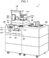
- FIG. 1 is a perspective view of a register counter 1.
- the register counter 1 is an example of a sales data processing device, and used for checkout in a bakery shop or the like.
- a salesperson as an operator stands behind the register counter 1 in FIG. 1
- a customer stands in front of the register counter 1. That is, the register counter 1 is used for checkout at a position interposed between the operator and the customer.
- the register counter 1 includes a POS terminal device 100, a payment machine 200, a cashier table 300, and a sacker table 400.
- the sacker table 400 is a work table having a flat upper surface, and used as a place for placing and packing merchandise.
- the POS terminal device 100 is placed on the upper surface of the casher table 300 and the payment machine 200 is also mounted on a front upper portion of the casher table 300.
- the cashier table 300 is provided to align an upper portion thereof with an upper surface of the sacker table 400 and functions as a table continuous from the sacker table 400.
- the cashier table 300 and the sacker table 400 include storage shelves 301 and 401 (see FIG. 2 ) that are open to an operator side.
- FIG. 2 illustrates an opposite side of the register counter 1 to the side shown in FIG. 1 , and is a perspective view showing an appearance of a peripheral portion of the POS terminal device 100 of the register counter 1.
- the POS terminal device 100 includes a main body unit 101, a control unit 102, a keyboard 103, a touch panel 104, a display unit 105, a sub display unit 106 (see FIG. 1 ), a printer 107, and a printer table 108.
- the main body unit 101 is a base part of each unit, and the display unit 105 or the like in which the keyboard 103 is provided is attached thereto.
- the control unit 102 manages the POS terminal device 100 and the payment machine 200, and is configured with a central processing unit (CPU), a read only memory (ROM), a random access memory (RAM), and the like.
- the control unit 102 is accommodated in a thin box shape housing 102a under the main body unit 101.
- the main body unit 101 and the housing 102a are bodies separated from each other. Therefore, it is also possible to place the housing 102a including the control unit 102 on a storage shelf 301 or the like separated from the main body unit 101.
- the display unit 105 is provided to stand on the back side in FIG. 2 on an upper surface of the main body unit 101, and a screen is directed toward the operator, and displays information for the operator.
- the keyboard 103 and the touch panel 104 configure an operation unit.
- the keyboard 103 is provided on the front side of the upper surface of the main body unit 101.
- the touch panel 104 is provided on a front surface of the display unit 105 and receives an operation made in accordance with display content of the display unit 105.
- the sub display unit 106 is attached to the rear surface of the main body unit 101, directs a screen thereof toward the customer side, and displays information to be sent to the customer.
- a touch panel 109 is provided on a front surface of the sub display unit 106.
- the touch panel 109 receives an operation made in accordance with display content of the sub display unit 106.
- the sub display unit 106 and the touch panel 109 function as an example of a display operation unit.
- the payment machine 200 is an example of a cash handling unit, receives cash, and performs payment of change.
- the payment machine 200 includes a bill depositing and dispensing device 210, a coin depositing and dispensing device 220, and a cover 230.
- FIG. 3 is a perspective view of the payment machine 200 from which the cover 230 is removed.
- FIG. 3 illustrates a view seen from the same side as that of FIG. 1 (opposite side of FIG. 2 ).
- the bill depositing and dispensing device 210 includes a bill depositing unit 211, a bill dispensing unit 212, and a bill storage unit (not shown).
- the bill depositing unit 211 takes bills into a housing 213 from the outside.
- the bill storage unit is provided inside the housing 213, and accommodates the bills taken by the bill depositing unit 211.
- the bill dispensing unit 212 dispenses bills as changes by taking out the bills from the bill storage unit.
- the coin depositing and dispensing device 220 includes a coin depositing unit 221, a coin dispensing unit 222, and a coin storage unit (not shown).
- the coin depositing unit 221 takes coins into a housing 223 from the outside.
- the coin storage unit is provided inside the housing 223, and accommodates the coins taken by the coin depositing unit 221 therein.
- the coin dispensing unit 222 dispenses coins as changes by taking out the coins from the bill storage unit.
- the cover 230 covers the bill depositing and dispensing device 210 and the coin depositing and dispensing device 220, and prevents operation buttons or the like of the bill depositing and dispensing device 210 and the coin depositing and dispensing device 220 from being erroneously operated by the customer.
- the cover 230 includes a coin depositing port 231.
- the coin depositing port 231 is formed as a funnel shape, is located on the coin depositing unit 221, and guides the inserted coin to the coin depositing unit 221.
- the cover 230 includes holes for exposing the bill depositing unit 211 and the bill dispensing unit 212, and a hole for exposing the coin dispensing unit 222.
- Such a payment machine 200 receives deposit to the bill depositing unit 211 and the coin depositing unit 221, and cash equivalent to changes is dispensed from both or one of the bill dispensing unit 212 and the coin dispensing unit 222 in a case where the changes are necessary in relation to the depositing.
- the printer 107 prints and issues a receipt.
- the printer 107 is placed on the printer table 108.
- the orientation of the printer 107 can be changed with respect to the printer table 108.
- the printer 107 of the embodiment is configured by selecting one of a customer orientation and an operator orientation. However, the orientation at the time of performing the embodiment may be selected as three or more orientations.
- FIG. 4 is a perspective view of a peripheral portion of the POS terminal device 100 of the register counter 1.
- FIG. 4 illustrates a view seen from the same side as that of FIG. 2 . Difference between FIG. 2 and FIG. 4 is the orientation of the printer 107.
- the printer 107 uses a paper discharge port 107a for discharging the receipt toward a customer side or an operator side.
- FIG. 1 to FIG. 3 illustrate a state where the paper discharge port 107a faces the customer side.
- FIG. 4 illustrates a state where the paper discharge port 107a faces the operator side.
- the printer 107 includes four legs 107b on a bottom surface thereof.
- the legs 107b are made of, for example, rubber in order to reduce transmission of vibrations or to prevent positional deviation due to slipping.
- FIG. 5A is a perspective view of the printer table 108.
- FIG. 5B is an exploded perspective view showing a structure of the printer table 108.
- the printer table 108 includes a base 810 and a top plate 820.
- the base 810 includes a leg portion 811 and a base portion 812.
- the leg portion 811 is a portion attached to the main body unit 101, and the base portion 812 is fixed on an upper portion thereof.
- the base portion 812 is an approximately horizontal flat plate shape portion having the same size and shape as those of the printer 107 projected in a plan view, and is located on the leg portion 811.
- the base portion 812 includes a hole 813 through which a cable (not shown) for connecting the main body unit 101 and the printer 107 passes.
- the top plate 820 is a metal sheet that directly supports the printer 107, and is fit in the base portion 812.
- the top plate 820 includes claws 821 for precisely setting positions of the legs 107b of the printer 107.
- the top plate 820 includes a hole 822 for passing through the cable passing through the hole 813.
- the top plate 820 is fit in a position lower than an upper end of a rib 814 in which the base portion 812 is implemented on an outer peripheral portion.
- the control unit 102 is an example of a data processing unit, and performs registration of an item to be sold to a customer and calculation of the price of the item based on an operation received by the operation unit. In addition, the control unit 102 receives payment for price by the payment machine 200.
- the operator stands on the back side in FIG. 1 and performs procedures related to checkout of merchandise placed on the sacker table 400 by customers who are on the front side in FIG. 1 .
- the operator visually checks the merchandise, performs the registration of the sales data through the POS terminal device 100, and requests the customer to pay the price.
- the customer deposits money to the payment machine 200 according to the amount of money requested, and receives changes if the changes are dispensed.
- the operator performs packing of the merchandise and filling of a bag, and hands over the merchandise to the customer after completing the checkout.
- the printer 107 discharges a receipt in which details of the purchased merchandise or the like are recorded in accordance with depositing and dispensing in the payment machine 200. If the paper discharge port 107a is directed toward the customer side, the customer takes directly the receipt. In addition, if the paper discharge port 107a is directed toward the operator side, the operator hands over the receipt to the customer.
- the orientation of the paper discharge port 107a of the printer 107 it is possible to determine the orientation of the paper discharge port 107a of the printer 107 according to the store policy. For example, since there is no hygienic problem for the receipt unlike the cash, a polite impression may be given to the customer by handing over the receipt to the customer by the operator, or a time required for checkout may be reduced by taking the receipt by the customers.
Landscapes
- Physics & Mathematics (AREA)
- General Physics & Mathematics (AREA)
- Business, Economics & Management (AREA)
- Accounting & Taxation (AREA)
- Finance (AREA)
- Strategic Management (AREA)
- General Business, Economics & Management (AREA)
- Engineering & Computer Science (AREA)
- Theoretical Computer Science (AREA)
- Cash Registers Or Receiving Machines (AREA)
Abstract
Description
- The present invention relates to a data processing technology in general, and embodiments described herein relate in particular to a point-of-sale (POS) system.
- In the related art, sales data processing devices such as registers, POS terminal devices, self-service checkout devices, and semi-self-service checkout devices are used in retailers. For example, in a bakery, fast food shops, and the like, an operator of the sales data processing device may handle cash for payment, and also packaging or bagging of food products, especially, non-packaged food products. Since cash is generally touched by many people throughout circulation, infectious bacterium and virus may spread. For that reason, it is more preferable that operators dealing with food products do not touch cash when the operator handles food products at the checkout. Further, even in a retailer dealing with non-food products, it may be preferable that operators do not handle cash.
- To this end, there is provided a point-of-sale (POS) system comprising:
- a cash processing machine having a cash receiving port and a cash dispensing port disposed on a first lateral side thereof;
- a register machine having a display and an operational panel and coupled with the cash processing machine such that the display and the operational panel face a second lateral side of the cash processing machine that is opposite to the first lateral side; and
- a receipt printer having a receipt outlet from which a receipt is ejected, the receipt printer being movable between a first position in which the receipt outlet is closer to the first lateral side than the second lateral side and a second position in which the receipt outlet is closer to the second lateral side than the first lateral side.
- Preferably, the receipt printer is placed on a top surface of a platform formed in the register machine.
- Preferably still, the platform includes a main body and a top plate that is attached to the main body and on which the receipt printer is placed.
- Preferably yet, the top plate includes one or more guides on a first end portion thereof and one or more guides on a second end portion that is opposite to the first end portion, the one or more guides on the first end portion and the one or more guides on the second end portion are spaced apart such that a bottom portion of the receipt printer fits therebetween and a move of the receipt printer in a direction from the first end portion to the second end portion and in a direction from the second end portion to the first end portion is restricted.
- Conveniently, each of the one or more guides on the first end portion comprises a protrusion that extends upward and has a surface formed along an edge of the top plate in the first end portion, and
each of the one or more guides on the second end portion comprises a protrusion that extends upward and has a surface formed along an edge of the top plate in the second end portion. - Conveniently still, the first end portion of the top plate faces a same side as the operation panel.
- Conveniently yet, each of the main body and the top plate of the platform has an opening through which a cable connected to the receipt printer passes.
- Suitably, the receipt printer is coupled with the register machine, such that the receipt outlet of the receipt printer faces the first lateral side to eject the receipt towards the first lateral side.
- Suitably still, the receipt printer is coupled with the register machine, such that the receipt outlet of the receipt printer faces the second lateral side to eject the receipt towards the second lateral side.
- Suitably yet; the register machine is detachably placed above a top surface of the cash processing machine.
- Suitably further, the cash receiving port includes a coin receiving port and a bill receiving port both of which face upward.
- Typically, the cash dispensing port includes a coin dispensing port and a bill dispensing port both of which face upward.
- Typically further, the register machine further includes a second display facing in a direction opposite to a direction in which the display faces.
- The above and other objects, features and advantages of the present invention will be made apparent from the following description of the preferred embodiments, given as non-limiting examples, with reference to the accompanying drawings, in which:
-
FIG. 1 is a perspective view of a register counter according to an embodiment. -
FIG. 2 is a perspective view of a peripheral portion of a POS terminal device of the register counter. -
FIG. 3 is a perspective view of a payment machine of which a cover is removed. -
FIG. 4 is a perspective view of a peripheral portion of a POS terminal device of the register counter. -
FIG. 5A is a perspective view of a printer table. -
FIG. 5B is an exploded perspective view of the printer table. - An embodiment provides a sales data processing device that enables cash-based checkout without touching cash by an operator.
- In general, according to an embodiment, a point-of-sale (POS) system includes a cash processing machine, a register machine, and a receipt printer. The cash processing machine has a cash receiving port and a cash dispensing port disposed on a first lateral side thereof. The register machine has a display and an operational panel and is coupled with the cash processing machine such that the display and the operational panel face a second lateral side of the cash processing machine that is opposite to the first lateral side. The receipt printer has a receipt outlet from which a receipt is ejected, and is movable between a first position in which the receipt outlet is closer to the first lateral side than the second lateral side and a second position in which the receipt outlet is closer to the second lateral side than the first lateral side.
- An embodiment will be described with reference to the drawings.
FIG. 1 is a perspective view of a register counter 1. For example, the register counter 1 is an example of a sales data processing device, and used for checkout in a bakery shop or the like. For checkout, a salesperson as an operator stands behind the register counter 1 inFIG. 1 , and a customer stands in front of the register counter 1. That is, the register counter 1 is used for checkout at a position interposed between the operator and the customer. - The register counter 1 includes a
POS terminal device 100, apayment machine 200, a cashier table 300, and a sacker table 400. - The sacker table 400 is a work table having a flat upper surface, and used as a place for placing and packing merchandise. The
POS terminal device 100 is placed on the upper surface of the casher table 300 and thepayment machine 200 is also mounted on a front upper portion of the casher table 300. In addition, the cashier table 300 is provided to align an upper portion thereof with an upper surface of the sacker table 400 and functions as a table continuous from the sacker table 400. The cashier table 300 and the sacker table 400 includestorage shelves 301 and 401 (seeFIG. 2 ) that are open to an operator side. -
FIG. 2 illustrates an opposite side of the register counter 1 to the side shown inFIG. 1 , and is a perspective view showing an appearance of a peripheral portion of thePOS terminal device 100 of the register counter 1. ThePOS terminal device 100 includes amain body unit 101, acontrol unit 102, akeyboard 103, atouch panel 104, adisplay unit 105, a sub display unit 106 (seeFIG. 1 ), aprinter 107, and a printer table 108. - The
main body unit 101 is a base part of each unit, and thedisplay unit 105 or the like in which thekeyboard 103 is provided is attached thereto. - The
control unit 102 manages thePOS terminal device 100 and thepayment machine 200, and is configured with a central processing unit (CPU), a read only memory (ROM), a random access memory (RAM), and the like. Thecontrol unit 102 is accommodated in a thinbox shape housing 102a under themain body unit 101. - The
main body unit 101 and thehousing 102a are bodies separated from each other. Therefore, it is also possible to place thehousing 102a including thecontrol unit 102 on astorage shelf 301 or the like separated from themain body unit 101. - The
display unit 105 is provided to stand on the back side inFIG. 2 on an upper surface of themain body unit 101, and a screen is directed toward the operator, and displays information for the operator. - The
keyboard 103 and thetouch panel 104 configure an operation unit. Thekeyboard 103 is provided on the front side of the upper surface of themain body unit 101. Thetouch panel 104 is provided on a front surface of thedisplay unit 105 and receives an operation made in accordance with display content of thedisplay unit 105. - The
sub display unit 106 is attached to the rear surface of themain body unit 101, directs a screen thereof toward the customer side, and displays information to be sent to the customer. In addition, atouch panel 109 is provided on a front surface of thesub display unit 106. Thetouch panel 109 receives an operation made in accordance with display content of thesub display unit 106. Thesub display unit 106 and thetouch panel 109 function as an example of a display operation unit. - The
payment machine 200 is an example of a cash handling unit, receives cash, and performs payment of change. Thepayment machine 200 includes a bill depositing and dispensingdevice 210, a coin depositing and dispensingdevice 220, and acover 230.FIG. 3 is a perspective view of thepayment machine 200 from which thecover 230 is removed.FIG. 3 illustrates a view seen from the same side as that ofFIG. 1 (opposite side ofFIG. 2 ). - The bill depositing and dispensing
device 210 includes abill depositing unit 211, abill dispensing unit 212, and a bill storage unit (not shown). Thebill depositing unit 211 takes bills into ahousing 213 from the outside. The bill storage unit is provided inside thehousing 213, and accommodates the bills taken by thebill depositing unit 211. Thebill dispensing unit 212 dispenses bills as changes by taking out the bills from the bill storage unit. - The coin depositing and dispensing
device 220 includes acoin depositing unit 221, acoin dispensing unit 222, and a coin storage unit (not shown). Thecoin depositing unit 221 takes coins into ahousing 223 from the outside. The coin storage unit is provided inside thehousing 223, and accommodates the coins taken by thecoin depositing unit 221 therein. Thecoin dispensing unit 222 dispenses coins as changes by taking out the coins from the bill storage unit. - The
cover 230 covers the bill depositing and dispensingdevice 210 and the coin depositing and dispensingdevice 220, and prevents operation buttons or the like of the bill depositing and dispensingdevice 210 and the coin depositing and dispensingdevice 220 from being erroneously operated by the customer. - The
cover 230 includes acoin depositing port 231. Thecoin depositing port 231 is formed as a funnel shape, is located on thecoin depositing unit 221, and guides the inserted coin to thecoin depositing unit 221. In addition, thecover 230 includes holes for exposing thebill depositing unit 211 and thebill dispensing unit 212, and a hole for exposing thecoin dispensing unit 222. - Such a
payment machine 200 receives deposit to thebill depositing unit 211 and thecoin depositing unit 221, and cash equivalent to changes is dispensed from both or one of thebill dispensing unit 212 and thecoin dispensing unit 222 in a case where the changes are necessary in relation to the depositing. - The
printer 107 prints and issues a receipt. Theprinter 107 is placed on the printer table 108. The orientation of theprinter 107 can be changed with respect to the printer table 108. Theprinter 107 of the embodiment is configured by selecting one of a customer orientation and an operator orientation. However, the orientation at the time of performing the embodiment may be selected as three or more orientations. -
FIG. 4 is a perspective view of a peripheral portion of thePOS terminal device 100 of the register counter 1.FIG. 4 illustrates a view seen from the same side as that ofFIG. 2 . Difference betweenFIG. 2 andFIG. 4 is the orientation of theprinter 107. Theprinter 107 uses apaper discharge port 107a for discharging the receipt toward a customer side or an operator side.FIG. 1 to FIG. 3 illustrate a state where thepaper discharge port 107a faces the customer side.FIG. 4 illustrates a state where thepaper discharge port 107a faces the operator side. - In addition, the
printer 107 includes fourlegs 107b on a bottom surface thereof. Thelegs 107b are made of, for example, rubber in order to reduce transmission of vibrations or to prevent positional deviation due to slipping. -
FIG. 5A is a perspective view of the printer table 108.FIG. 5B is an exploded perspective view showing a structure of the printer table 108. The printer table 108 includes abase 810 and atop plate 820. - The
base 810 includes aleg portion 811 and abase portion 812. Theleg portion 811 is a portion attached to themain body unit 101, and thebase portion 812 is fixed on an upper portion thereof. Thebase portion 812 is an approximately horizontal flat plate shape portion having the same size and shape as those of theprinter 107 projected in a plan view, and is located on theleg portion 811. Thebase portion 812 includes ahole 813 through which a cable (not shown) for connecting themain body unit 101 and theprinter 107 passes. - The
top plate 820 is a metal sheet that directly supports theprinter 107, and is fit in thebase portion 812. Thetop plate 820 includesclaws 821 for precisely setting positions of thelegs 107b of theprinter 107. In addition, thetop plate 820 includes ahole 822 for passing through the cable passing through thehole 813. Thetop plate 820 is fit in a position lower than an upper end of arib 814 in which thebase portion 812 is implemented on an outer peripheral portion. - The
control unit 102 is an example of a data processing unit, and performs registration of an item to be sold to a customer and calculation of the price of the item based on an operation received by the operation unit. In addition, thecontrol unit 102 receives payment for price by thepayment machine 200. - In the register counter 1 of the configuration described above, the operator stands on the back side in
FIG. 1 and performs procedures related to checkout of merchandise placed on the sacker table 400 by customers who are on the front side inFIG. 1 . - The operator visually checks the merchandise, performs the registration of the sales data through the
POS terminal device 100, and requests the customer to pay the price. The customer deposits money to thepayment machine 200 according to the amount of money requested, and receives changes if the changes are dispensed. In addition, the operator performs packing of the merchandise and filling of a bag, and hands over the merchandise to the customer after completing the checkout. - The
printer 107 discharges a receipt in which details of the purchased merchandise or the like are recorded in accordance with depositing and dispensing in thepayment machine 200. If thepaper discharge port 107a is directed toward the customer side, the customer takes directly the receipt. In addition, if thepaper discharge port 107a is directed toward the operator side, the operator hands over the receipt to the customer. - According to such an embodiment, since the operator can complete checkout without touching cash, it is possible to realize a sanitary operation, and it is possible to expect an effect of reducing spreading path of infectious diseases.
- In addition, according to the configuration of the present embodiment, it is possible to determine the orientation of the
paper discharge port 107a of theprinter 107 according to the store policy. For example, since there is no hygienic problem for the receipt unlike the cash, a polite impression may be given to the customer by handing over the receipt to the customer by the operator, or a time required for checkout may be reduced by taking the receipt by the customers. - While certain embodiments have been described, these embodiments have been presented by way of example only, and are not intended to limit the scope of the inventions. Indeed, the novel embodiments described herein may be embodied in a variety of other forms; furthermore, various omissions, substitutions and changes in the form of the embodiments described herein may be made without departing from the framework of the inventions. The accompanying claims and their equivalents are intended to cover such forms or modifications as would fall within the scope and framework of the inventions.
Claims (13)
- A point-of-sale (POS) system comprising:a cash processing machine having a cash receiving port and a cash dispensing port disposed on a first lateral side thereof;a register machine having a display and an operational panel and coupled with the cash processing machine such that the display and the operational panel face a second lateral side of the cash processing machine that is opposite to the first lateral side; anda receipt printer having a receipt outlet from which a receipt is ejected, the receipt printer being movable between a first position in which the receipt outlet is closer to the first lateral side than the second lateral side and a second position in which the receipt outlet is closer to the second lateral side than the first lateral side.
- The POS system according to claim 1, wherein the receipt printer is placed on a top surface of a platform formed in the register machine.
- The POS system according to claim 2, wherein the platform includes a main body and a top plate that is attached to the main body and on which the receipt printer is placed.
- The POS system according to claim 3, wherein the top plate includes one or more guides on a first end portion thereof and one or more guides on a second end portion that is opposite to the first end portion, the one or more guides on the first end portion and the one or more guides on the second end portion are spaced apart such that a bottom portion of the receipt printer fits therebetween and a move of the receipt printer in a direction from the first end portion to the second end portion and in a direction from the second end portion to the first end portion is restricted.
- The POS system according to claim 4, wherein
each of the one or more guides on the first end portion comprises a protrusion that extends upward and has a surface formed along an edge of the top plate in the first end portion, and
each of the one or more guides on the second end portion comprises a protrusion that extends upward and has a surface formed along an edge of the top plate in the second end portion. - The POS system according to claim 4, wherein the first end portion of the top plate faces a same side as the operation panel.
- The POS system according to claim 4, wherein each of the main body and the top plate of the platform has an opening through which a cable connected to the receipt printer passes.
- The POS system according to any one of claims 1 to 7, wherein the receipt printer is coupled with the register machine, such that the receipt outlet of the receipt printer faces the first lateral side to eject the receipt towards the first lateral side.
- The POS system according to any one of claims 1 to 8, wherein the receipt printer is coupled with the register machine, such that the receipt outlet of the receipt printer faces the second lateral side to eject the receipt towards the second lateral side.
- The POS system according to any one of claims 1 to 9, wherein the register machine is detachably placed above a top surface of the cash processing machine.
- The POS system according to any one of claims 1 to 10, wherein the cash receiving port includes a coin receiving port and a bill receiving port both of which face upward.
- The POS system according to claim 11, wherein the cash dispensing port includes a coin dispensing port and a bill dispensing port both of which face upward.
- The POS system according to any one of claims 1 to 12, wherein the register machine further includes a second display facing in a direction opposite to a direction in which the display faces.
Applications Claiming Priority (1)
| Application Number | Priority Date | Filing Date | Title |
|---|---|---|---|
| JP2016185587A JP6815803B2 (en) | 2016-09-23 | 2016-09-23 | Sales data processing equipment |
Publications (2)
| Publication Number | Publication Date |
|---|---|
| EP3300010A1 true EP3300010A1 (en) | 2018-03-28 |
| EP3300010B1 EP3300010B1 (en) | 2022-05-11 |
Family
ID=59856418
Family Applications (1)
| Application Number | Title | Priority Date | Filing Date |
|---|---|---|---|
| EP17190481.6A Not-in-force EP3300010B1 (en) | 2016-09-23 | 2017-09-11 | Point-of-sale system with movable receipt printer |
Country Status (4)
| Country | Link |
|---|---|
| US (1) | US10726409B2 (en) |
| EP (1) | EP3300010B1 (en) |
| JP (1) | JP6815803B2 (en) |
| CN (1) | CN207149007U (en) |
Families Citing this family (1)
| Publication number | Priority date | Publication date | Assignee | Title |
|---|---|---|---|---|
| JP7141087B2 (en) * | 2018-05-02 | 2022-09-22 | 株式会社寺岡精工 | sales data processor |
Citations (6)
| Publication number | Priority date | Publication date | Assignee | Title |
|---|---|---|---|---|
| EP0798122A2 (en) * | 1996-02-29 | 1997-10-01 | Seiko Epson Corporation | Printing apparatus comprising plural printer units |
| US6286758B1 (en) * | 1999-02-17 | 2001-09-11 | Ncr Corporation | Reconfigurable checkout system |
| US20120224201A1 (en) * | 2011-03-02 | 2012-09-06 | Toshiba Tec Kabushiki Kaisha | Printing device and printing method thereof |
| US20150145915A1 (en) * | 2013-11-22 | 2015-05-28 | Toshiba Global Commerce Solutions Holdings Corporation | Printers and printer systems for printing images on paper in different configurations and for dispensing printed paper in different directions |
| WO2016013230A1 (en) * | 2014-07-25 | 2016-01-28 | Toshiba Global Commerce Solutions Holdings Corporation | Reconfigurable checkout station |
| GB2535970A (en) * | 2014-10-29 | 2016-09-07 | Number 8 Tech Ltd | Retail transaction system |
Family Cites Families (20)
| Publication number | Priority date | Publication date | Assignee | Title |
|---|---|---|---|---|
| DE29703847U1 (en) * | 1997-03-03 | 1997-05-07 | Siemens Nixdorf Informationssysteme AG, 33106 Paderborn | Modular control unit for the retail sector |
| US5969691A (en) * | 1998-02-10 | 1999-10-19 | Gilbarco Inc. | Fuel dispenser transponder antenna arrangement |
| CA2384604A1 (en) * | 2001-05-04 | 2002-11-04 | Phillip S. Kerber | Retail store checkout assembly, point-of-sale equipment stand, and arrangements |
| JP4029612B2 (en) * | 2001-12-25 | 2008-01-09 | カシオ計算機株式会社 | Money storage device |
| US20060038009A1 (en) * | 2002-01-11 | 2006-02-23 | Metrologic Instruments, Inc. | Point of sale (POS) based bar code reading and cash register systems with integrated internet-enabled customer-kiosk terminals |
| US8033375B2 (en) * | 2002-02-15 | 2011-10-11 | Coinstar, Inc. | Methods and systems for exchanging and/or transferring various forms of value |
| US20110047092A1 (en) * | 2005-03-04 | 2011-02-24 | Taylor H Davis | System and method for tracking and managing transportation of specimens |
| US7866546B1 (en) * | 2006-04-21 | 2011-01-11 | Pan-Oston | Automated checkout unit and method of use thereof |
| JP4482710B2 (en) * | 2008-02-04 | 2010-06-16 | Necインフロンティア株式会社 | POS equipment |
| US20100191603A1 (en) * | 2009-01-26 | 2010-07-29 | Nathaniel Christopher Herwig | Transaction station with enhanced user interface |
| US8944322B2 (en) * | 2011-07-15 | 2015-02-03 | Wal-Mart Stores, Inc. | Tri-optic scanner |
| GB2505867A (en) * | 2012-07-11 | 2014-03-19 | Digipos Store Solutions Internat Ltd | Modular point-of-sale terminal |
| CN202816050U (en) * | 2012-08-29 | 2013-03-20 | 广东川田科技有限公司 | Embedded touch POS machine |
| US9582793B2 (en) * | 2013-03-11 | 2017-02-28 | Certefi, Inc. | Point of sale system, inventory system, and methods thereof |
| EP3786509B1 (en) * | 2013-03-29 | 2026-01-28 | First Data Corporation | Systems and methods for providing articulating point-of-sale apparatuses or devices |
| JP6044627B2 (en) * | 2014-06-23 | 2016-12-14 | 株式会社寺岡精工 | Product sales data processing apparatus and program |
| JP6007949B2 (en) * | 2014-07-31 | 2016-10-19 | 株式会社寺岡精工 | register |
| JP2016162147A (en) * | 2015-02-27 | 2016-09-05 | スター精密株式会社 | Printer/drawer-integrated type device and pos system |
| GB201511634D0 (en) * | 2015-07-02 | 2015-08-19 | Miura Systems Ltd | Integrated electronic device |
| JP6822808B2 (en) * | 2016-09-20 | 2021-01-27 | 東芝テック株式会社 | Payment device and its control program, as well as semi-self-checkout device |
-
2016
- 2016-09-23 JP JP2016185587A patent/JP6815803B2/en active Active
-
2017
- 2017-08-18 CN CN201721037567.1U patent/CN207149007U/en not_active Expired - Fee Related
- 2017-09-11 EP EP17190481.6A patent/EP3300010B1/en not_active Not-in-force
- 2017-09-14 US US15/704,059 patent/US10726409B2/en active Active
Patent Citations (6)
| Publication number | Priority date | Publication date | Assignee | Title |
|---|---|---|---|---|
| EP0798122A2 (en) * | 1996-02-29 | 1997-10-01 | Seiko Epson Corporation | Printing apparatus comprising plural printer units |
| US6286758B1 (en) * | 1999-02-17 | 2001-09-11 | Ncr Corporation | Reconfigurable checkout system |
| US20120224201A1 (en) * | 2011-03-02 | 2012-09-06 | Toshiba Tec Kabushiki Kaisha | Printing device and printing method thereof |
| US20150145915A1 (en) * | 2013-11-22 | 2015-05-28 | Toshiba Global Commerce Solutions Holdings Corporation | Printers and printer systems for printing images on paper in different configurations and for dispensing printed paper in different directions |
| WO2016013230A1 (en) * | 2014-07-25 | 2016-01-28 | Toshiba Global Commerce Solutions Holdings Corporation | Reconfigurable checkout station |
| GB2535970A (en) * | 2014-10-29 | 2016-09-07 | Number 8 Tech Ltd | Retail transaction system |
Also Published As
| Publication number | Publication date |
|---|---|
| JP6815803B2 (en) | 2021-01-20 |
| JP2018049531A (en) | 2018-03-29 |
| US20180089659A1 (en) | 2018-03-29 |
| EP3300010B1 (en) | 2022-05-11 |
| US10726409B2 (en) | 2020-07-28 |
| CN207149007U (en) | 2018-03-27 |
Similar Documents
| Publication | Publication Date | Title |
|---|---|---|
| JP5811295B1 (en) | Settlement processing unit assembly and cradle for settlement processing unit assembly | |
| JP6551474B2 (en) | Product sales data processing device | |
| JP2013045353A (en) | Goods sold sales register data processor | |
| US10950098B2 (en) | Cash processing apparatus | |
| JP7519240B2 (en) | Checkout Device | |
| US20170224134A1 (en) | Money depositing/dispensing apparatus | |
| JP7678195B2 (en) | Self-checkout device | |
| JP6693087B2 (en) | Payment device | |
| US10726409B2 (en) | Point-of-sale system with movable receipt printer | |
| US20180240310A1 (en) | Self-service point-of-sale terminal | |
| JP2015156138A (en) | Commodity sales data processor | |
| JP6376993B2 (en) | Self-checkout device | |
| JP6240110B2 (en) | Sales data processor | |
| JP2016149115A (en) | Checkout machine assembly | |
| JP7090689B2 (en) | Sales data processing equipment | |
| JP2021128383A (en) | Bag supply device and product sales data processing device | |
| JP6637454B2 (en) | Self checkout device | |
| JP2018018554A (en) | Sales data processing device | |
| JP2016162192A (en) | Sales data processing device | |
| JP6666398B2 (en) | Payment device | |
| JP2020095755A (en) | Settlement device | |
| JP7141087B2 (en) | sales data processor | |
| JP2018132888A (en) | Product sales data processing device | |
| JP6395878B2 (en) | Payment device | |
| JP6522197B2 (en) | Payment device |
Legal Events
| Date | Code | Title | Description |
|---|---|---|---|
| PUAI | Public reference made under article 153(3) epc to a published international application that has entered the european phase |
Free format text: ORIGINAL CODE: 0009012 |
|
| STAA | Information on the status of an ep patent application or granted ep patent |
Free format text: STATUS: THE APPLICATION HAS BEEN PUBLISHED |
|
| AK | Designated contracting states |
Kind code of ref document: A1 Designated state(s): AL AT BE BG CH CY CZ DE DK EE ES FI FR GB GR HR HU IE IS IT LI LT LU LV MC MK MT NL NO PL PT RO RS SE SI SK SM TR |
|
| AX | Request for extension of the european patent |
Extension state: BA ME |
|
| STAA | Information on the status of an ep patent application or granted ep patent |
Free format text: STATUS: REQUEST FOR EXAMINATION WAS MADE |
|
| 17P | Request for examination filed |
Effective date: 20180928 |
|
| RBV | Designated contracting states (corrected) |
Designated state(s): AL AT BE BG CH CY CZ DE DK EE ES FI FR GB GR HR HU IE IS IT LI LT LU LV MC MK MT NL NO PL PT RO RS SE SI SK SM TR |
|
| STAA | Information on the status of an ep patent application or granted ep patent |
Free format text: STATUS: EXAMINATION IS IN PROGRESS |
|
| RIC1 | Information provided on ipc code assigned before grant |
Ipc: G07D 11/14 20190101ALI20200611BHEP Ipc: G07G 1/00 20060101ALI20200611BHEP Ipc: G06Q 20/20 20120101AFI20200611BHEP Ipc: G07G 5/00 20060101ALI20200611BHEP Ipc: B41J 15/04 20060101ALI20200611BHEP |
|
| 17Q | First examination report despatched |
Effective date: 20200625 |
|
| GRAP | Despatch of communication of intention to grant a patent |
Free format text: ORIGINAL CODE: EPIDOSNIGR1 |
|
| STAA | Information on the status of an ep patent application or granted ep patent |
Free format text: STATUS: GRANT OF PATENT IS INTENDED |
|
| INTG | Intention to grant announced |
Effective date: 20211215 |
|
| GRAS | Grant fee paid |
Free format text: ORIGINAL CODE: EPIDOSNIGR3 |
|
| GRAA | (expected) grant |
Free format text: ORIGINAL CODE: 0009210 |
|
| STAA | Information on the status of an ep patent application or granted ep patent |
Free format text: STATUS: THE PATENT HAS BEEN GRANTED |
|
| AK | Designated contracting states |
Kind code of ref document: B1 Designated state(s): AL AT BE BG CH CY CZ DE DK EE ES FI FR GB GR HR HU IE IS IT LI LT LU LV MC MK MT NL NO PL PT RO RS SE SI SK SM TR |
|
| REG | Reference to a national code |
Ref country code: GB Ref legal event code: FG4D |
|
| REG | Reference to a national code |
Ref country code: CH Ref legal event code: EP |
|
| REG | Reference to a national code |
Ref country code: AT Ref legal event code: REF Ref document number: 1492086 Country of ref document: AT Kind code of ref document: T Effective date: 20220515 |
|
| REG | Reference to a national code |
Ref country code: DE Ref legal event code: R096 Ref document number: 602017057254 Country of ref document: DE |
|
| REG | Reference to a national code |
Ref country code: IE Ref legal event code: FG4D |
|
| REG | Reference to a national code |
Ref country code: LT Ref legal event code: MG9D |
|
| REG | Reference to a national code |
Ref country code: NL Ref legal event code: MP Effective date: 20220511 |
|
| REG | Reference to a national code |
Ref country code: AT Ref legal event code: MK05 Ref document number: 1492086 Country of ref document: AT Kind code of ref document: T Effective date: 20220511 |
|
| PG25 | Lapsed in a contracting state [announced via postgrant information from national office to epo] |
Ref country code: SE Free format text: LAPSE BECAUSE OF FAILURE TO SUBMIT A TRANSLATION OF THE DESCRIPTION OR TO PAY THE FEE WITHIN THE PRESCRIBED TIME-LIMIT Effective date: 20220511 Ref country code: PT Free format text: LAPSE BECAUSE OF FAILURE TO SUBMIT A TRANSLATION OF THE DESCRIPTION OR TO PAY THE FEE WITHIN THE PRESCRIBED TIME-LIMIT Effective date: 20220912 Ref country code: NO Free format text: LAPSE BECAUSE OF FAILURE TO SUBMIT A TRANSLATION OF THE DESCRIPTION OR TO PAY THE FEE WITHIN THE PRESCRIBED TIME-LIMIT Effective date: 20220811 Ref country code: NL Free format text: LAPSE BECAUSE OF FAILURE TO SUBMIT A TRANSLATION OF THE DESCRIPTION OR TO PAY THE FEE WITHIN THE PRESCRIBED TIME-LIMIT Effective date: 20220511 Ref country code: LT Free format text: LAPSE BECAUSE OF FAILURE TO SUBMIT A TRANSLATION OF THE DESCRIPTION OR TO PAY THE FEE WITHIN THE PRESCRIBED TIME-LIMIT Effective date: 20220511 Ref country code: HR Free format text: LAPSE BECAUSE OF FAILURE TO SUBMIT A TRANSLATION OF THE DESCRIPTION OR TO PAY THE FEE WITHIN THE PRESCRIBED TIME-LIMIT Effective date: 20220511 Ref country code: GR Free format text: LAPSE BECAUSE OF FAILURE TO SUBMIT A TRANSLATION OF THE DESCRIPTION OR TO PAY THE FEE WITHIN THE PRESCRIBED TIME-LIMIT Effective date: 20220812 Ref country code: FI Free format text: LAPSE BECAUSE OF FAILURE TO SUBMIT A TRANSLATION OF THE DESCRIPTION OR TO PAY THE FEE WITHIN THE PRESCRIBED TIME-LIMIT Effective date: 20220511 Ref country code: ES Free format text: LAPSE BECAUSE OF FAILURE TO SUBMIT A TRANSLATION OF THE DESCRIPTION OR TO PAY THE FEE WITHIN THE PRESCRIBED TIME-LIMIT Effective date: 20220511 Ref country code: BG Free format text: LAPSE BECAUSE OF FAILURE TO SUBMIT A TRANSLATION OF THE DESCRIPTION OR TO PAY THE FEE WITHIN THE PRESCRIBED TIME-LIMIT Effective date: 20220811 Ref country code: AT Free format text: LAPSE BECAUSE OF FAILURE TO SUBMIT A TRANSLATION OF THE DESCRIPTION OR TO PAY THE FEE WITHIN THE PRESCRIBED TIME-LIMIT Effective date: 20220511 |
|
| PG25 | Lapsed in a contracting state [announced via postgrant information from national office to epo] |
Ref country code: RS Free format text: LAPSE BECAUSE OF FAILURE TO SUBMIT A TRANSLATION OF THE DESCRIPTION OR TO PAY THE FEE WITHIN THE PRESCRIBED TIME-LIMIT Effective date: 20220511 Ref country code: PL Free format text: LAPSE BECAUSE OF FAILURE TO SUBMIT A TRANSLATION OF THE DESCRIPTION OR TO PAY THE FEE WITHIN THE PRESCRIBED TIME-LIMIT Effective date: 20220511 Ref country code: LV Free format text: LAPSE BECAUSE OF FAILURE TO SUBMIT A TRANSLATION OF THE DESCRIPTION OR TO PAY THE FEE WITHIN THE PRESCRIBED TIME-LIMIT Effective date: 20220511 Ref country code: IS Free format text: LAPSE BECAUSE OF FAILURE TO SUBMIT A TRANSLATION OF THE DESCRIPTION OR TO PAY THE FEE WITHIN THE PRESCRIBED TIME-LIMIT Effective date: 20220911 |
|
| PG25 | Lapsed in a contracting state [announced via postgrant information from national office to epo] |
Ref country code: SM Free format text: LAPSE BECAUSE OF FAILURE TO SUBMIT A TRANSLATION OF THE DESCRIPTION OR TO PAY THE FEE WITHIN THE PRESCRIBED TIME-LIMIT Effective date: 20220511 Ref country code: SK Free format text: LAPSE BECAUSE OF FAILURE TO SUBMIT A TRANSLATION OF THE DESCRIPTION OR TO PAY THE FEE WITHIN THE PRESCRIBED TIME-LIMIT Effective date: 20220511 Ref country code: RO Free format text: LAPSE BECAUSE OF FAILURE TO SUBMIT A TRANSLATION OF THE DESCRIPTION OR TO PAY THE FEE WITHIN THE PRESCRIBED TIME-LIMIT Effective date: 20220511 Ref country code: EE Free format text: LAPSE BECAUSE OF FAILURE TO SUBMIT A TRANSLATION OF THE DESCRIPTION OR TO PAY THE FEE WITHIN THE PRESCRIBED TIME-LIMIT Effective date: 20220511 Ref country code: DK Free format text: LAPSE BECAUSE OF FAILURE TO SUBMIT A TRANSLATION OF THE DESCRIPTION OR TO PAY THE FEE WITHIN THE PRESCRIBED TIME-LIMIT Effective date: 20220511 Ref country code: CZ Free format text: LAPSE BECAUSE OF FAILURE TO SUBMIT A TRANSLATION OF THE DESCRIPTION OR TO PAY THE FEE WITHIN THE PRESCRIBED TIME-LIMIT Effective date: 20220511 |
|
| REG | Reference to a national code |
Ref country code: DE Ref legal event code: R097 Ref document number: 602017057254 Country of ref document: DE |
|
| PLBE | No opposition filed within time limit |
Free format text: ORIGINAL CODE: 0009261 |
|
| STAA | Information on the status of an ep patent application or granted ep patent |
Free format text: STATUS: NO OPPOSITION FILED WITHIN TIME LIMIT |
|
| PG25 | Lapsed in a contracting state [announced via postgrant information from national office to epo] |
Ref country code: AL Free format text: LAPSE BECAUSE OF FAILURE TO SUBMIT A TRANSLATION OF THE DESCRIPTION OR TO PAY THE FEE WITHIN THE PRESCRIBED TIME-LIMIT Effective date: 20220511 |
|
| 26N | No opposition filed |
Effective date: 20230214 |
|
| PG25 | Lapsed in a contracting state [announced via postgrant information from national office to epo] |
Ref country code: MC Free format text: LAPSE BECAUSE OF FAILURE TO SUBMIT A TRANSLATION OF THE DESCRIPTION OR TO PAY THE FEE WITHIN THE PRESCRIBED TIME-LIMIT Effective date: 20220511 |
|
| REG | Reference to a national code |
Ref country code: CH Ref legal event code: PL |
|
| REG | Reference to a national code |
Ref country code: BE Ref legal event code: MM Effective date: 20220930 |
|
| PG25 | Lapsed in a contracting state [announced via postgrant information from national office to epo] |
Ref country code: SI Free format text: LAPSE BECAUSE OF FAILURE TO SUBMIT A TRANSLATION OF THE DESCRIPTION OR TO PAY THE FEE WITHIN THE PRESCRIBED TIME-LIMIT Effective date: 20220511 |
|
| PG25 | Lapsed in a contracting state [announced via postgrant information from national office to epo] |
Ref country code: LU Free format text: LAPSE BECAUSE OF NON-PAYMENT OF DUE FEES Effective date: 20220911 |
|
| PG25 | Lapsed in a contracting state [announced via postgrant information from national office to epo] |
Ref country code: LI Free format text: LAPSE BECAUSE OF NON-PAYMENT OF DUE FEES Effective date: 20220930 Ref country code: IE Free format text: LAPSE BECAUSE OF NON-PAYMENT OF DUE FEES Effective date: 20220911 Ref country code: CH Free format text: LAPSE BECAUSE OF NON-PAYMENT OF DUE FEES Effective date: 20220930 |
|
| PG25 | Lapsed in a contracting state [announced via postgrant information from national office to epo] |
Ref country code: BE Free format text: LAPSE BECAUSE OF NON-PAYMENT OF DUE FEES Effective date: 20220930 |
|
| PGFP | Annual fee paid to national office [announced via postgrant information from national office to epo] |
Ref country code: GB Payment date: 20230720 Year of fee payment: 7 |
|
| PGFP | Annual fee paid to national office [announced via postgrant information from national office to epo] |
Ref country code: FR Payment date: 20230710 Year of fee payment: 7 Ref country code: DE Payment date: 20230718 Year of fee payment: 7 |
|
| PG25 | Lapsed in a contracting state [announced via postgrant information from national office to epo] |
Ref country code: IT Free format text: LAPSE BECAUSE OF FAILURE TO SUBMIT A TRANSLATION OF THE DESCRIPTION OR TO PAY THE FEE WITHIN THE PRESCRIBED TIME-LIMIT Effective date: 20220511 |
|
| PG25 | Lapsed in a contracting state [announced via postgrant information from national office to epo] |
Ref country code: HU Free format text: LAPSE BECAUSE OF FAILURE TO SUBMIT A TRANSLATION OF THE DESCRIPTION OR TO PAY THE FEE WITHIN THE PRESCRIBED TIME-LIMIT; INVALID AB INITIO Effective date: 20170911 |
|
| PG25 | Lapsed in a contracting state [announced via postgrant information from national office to epo] |
Ref country code: CY Free format text: LAPSE BECAUSE OF FAILURE TO SUBMIT A TRANSLATION OF THE DESCRIPTION OR TO PAY THE FEE WITHIN THE PRESCRIBED TIME-LIMIT Effective date: 20220511 |
|
| PG25 | Lapsed in a contracting state [announced via postgrant information from national office to epo] |
Ref country code: MK Free format text: LAPSE BECAUSE OF FAILURE TO SUBMIT A TRANSLATION OF THE DESCRIPTION OR TO PAY THE FEE WITHIN THE PRESCRIBED TIME-LIMIT Effective date: 20220511 |
|
| PG25 | Lapsed in a contracting state [announced via postgrant information from national office to epo] |
Ref country code: TR Free format text: LAPSE BECAUSE OF FAILURE TO SUBMIT A TRANSLATION OF THE DESCRIPTION OR TO PAY THE FEE WITHIN THE PRESCRIBED TIME-LIMIT Effective date: 20220511 |
|
| PG25 | Lapsed in a contracting state [announced via postgrant information from national office to epo] |
Ref country code: MT Free format text: LAPSE BECAUSE OF FAILURE TO SUBMIT A TRANSLATION OF THE DESCRIPTION OR TO PAY THE FEE WITHIN THE PRESCRIBED TIME-LIMIT Effective date: 20220511 |
|
| PG25 | Lapsed in a contracting state [announced via postgrant information from national office to epo] |
Ref country code: BG Free format text: LAPSE BECAUSE OF FAILURE TO SUBMIT A TRANSLATION OF THE DESCRIPTION OR TO PAY THE FEE WITHIN THE PRESCRIBED TIME-LIMIT Effective date: 20220511 |
|
| PG25 | Lapsed in a contracting state [announced via postgrant information from national office to epo] |
Ref country code: BG Free format text: LAPSE BECAUSE OF FAILURE TO SUBMIT A TRANSLATION OF THE DESCRIPTION OR TO PAY THE FEE WITHIN THE PRESCRIBED TIME-LIMIT Effective date: 20220511 |
|
| REG | Reference to a national code |
Ref country code: DE Ref legal event code: R119 Ref document number: 602017057254 Country of ref document: DE |
|
| GBPC | Gb: european patent ceased through non-payment of renewal fee |
Effective date: 20240911 |
|
| PG25 | Lapsed in a contracting state [announced via postgrant information from national office to epo] |
Ref country code: DE Free format text: LAPSE BECAUSE OF NON-PAYMENT OF DUE FEES Effective date: 20250401 |
|
| PG25 | Lapsed in a contracting state [announced via postgrant information from national office to epo] |
Ref country code: GB Free format text: LAPSE BECAUSE OF NON-PAYMENT OF DUE FEES Effective date: 20240911 |
|
| PG25 | Lapsed in a contracting state [announced via postgrant information from national office to epo] |
Ref country code: FR Free format text: LAPSE BECAUSE OF NON-PAYMENT OF DUE FEES Effective date: 20240930 |