EP3299924B1 - Système de décollage amélioré - Google Patents
Système de décollage amélioré Download PDFInfo
- Publication number
- EP3299924B1 EP3299924B1 EP17190574.8A EP17190574A EP3299924B1 EP 3299924 B1 EP3299924 B1 EP 3299924B1 EP 17190574 A EP17190574 A EP 17190574A EP 3299924 B1 EP3299924 B1 EP 3299924B1
- Authority
- EP
- European Patent Office
- Prior art keywords
- takeoff
- aircraft
- processor
- automatic
- control
- Prior art date
- Legal status (The legal status is an assumption and is not a legal conclusion. Google has not performed a legal analysis and makes no representation as to the accuracy of the status listed.)
- Active
Links
- 230000006870 function Effects 0.000 claims description 7
- 230000009467 reduction Effects 0.000 claims description 4
- 239000003381 stabilizer Substances 0.000 claims description 4
- 238000010586 diagram Methods 0.000 description 6
- 230000006872 improvement Effects 0.000 description 6
- 230000001133 acceleration Effects 0.000 description 3
- 230000009471 action Effects 0.000 description 3
- 238000000034 method Methods 0.000 description 3
- RZVHIXYEVGDQDX-UHFFFAOYSA-N 9,10-anthraquinone Chemical compound C1=CC=C2C(=O)C3=CC=CC=C3C(=O)C2=C1 RZVHIXYEVGDQDX-UHFFFAOYSA-N 0.000 description 2
- 230000001174 ascending effect Effects 0.000 description 2
- 230000003190 augmentative effect Effects 0.000 description 2
- 238000013461 design Methods 0.000 description 2
- 230000033001 locomotion Effects 0.000 description 2
- 238000012545 processing Methods 0.000 description 2
- 230000004044 response Effects 0.000 description 2
- 238000005096 rolling process Methods 0.000 description 2
- 239000000523 sample Substances 0.000 description 2
- 206010003830 Automatism Diseases 0.000 description 1
- 208000031963 Beta-mercaptolactate cysteine disulfiduria Diseases 0.000 description 1
- 230000004913 activation Effects 0.000 description 1
- 238000011217 control strategy Methods 0.000 description 1
- 230000003247 decreasing effect Effects 0.000 description 1
- 230000001419 dependent effect Effects 0.000 description 1
- 238000011161 development Methods 0.000 description 1
- 230000026058 directional locomotion Effects 0.000 description 1
- 230000005484 gravity Effects 0.000 description 1
- 238000010348 incorporation Methods 0.000 description 1
- 238000003780 insertion Methods 0.000 description 1
- 230000037431 insertion Effects 0.000 description 1
- 238000012544 monitoring process Methods 0.000 description 1
- 238000005457 optimization Methods 0.000 description 1
- 230000008569 process Effects 0.000 description 1
- 238000011160 research Methods 0.000 description 1
- 238000012360 testing method Methods 0.000 description 1
- 230000007704 transition Effects 0.000 description 1
- 230000000007 visual effect Effects 0.000 description 1
Images


Classifications
-
- G—PHYSICS
- G05—CONTROLLING; REGULATING
- G05D—SYSTEMS FOR CONTROLLING OR REGULATING NON-ELECTRIC VARIABLES
- G05D1/00—Control of position, course, altitude or attitude of land, water, air or space vehicles, e.g. using automatic pilots
- G05D1/10—Simultaneous control of position or course in three dimensions
- G05D1/101—Simultaneous control of position or course in three dimensions specially adapted for aircraft
-
- B—PERFORMING OPERATIONS; TRANSPORTING
- B64—AIRCRAFT; AVIATION; COSMONAUTICS
- B64C—AEROPLANES; HELICOPTERS
- B64C13/00—Control systems or transmitting systems for actuating flying-control surfaces, lift-increasing flaps, air brakes, or spoilers
- B64C13/02—Initiating means
- B64C13/16—Initiating means actuated automatically, e.g. responsive to gust detectors
- B64C13/18—Initiating means actuated automatically, e.g. responsive to gust detectors using automatic pilot
-
- B—PERFORMING OPERATIONS; TRANSPORTING
- B64—AIRCRAFT; AVIATION; COSMONAUTICS
- B64C—AEROPLANES; HELICOPTERS
- B64C13/00—Control systems or transmitting systems for actuating flying-control surfaces, lift-increasing flaps, air brakes, or spoilers
- B64C13/24—Transmitting means
- B64C13/38—Transmitting means with power amplification
- B64C13/50—Transmitting means with power amplification using electrical energy
- B64C13/503—Fly-by-Wire
-
- B—PERFORMING OPERATIONS; TRANSPORTING
- B64—AIRCRAFT; AVIATION; COSMONAUTICS
- B64C—AEROPLANES; HELICOPTERS
- B64C13/00—Control systems or transmitting systems for actuating flying-control surfaces, lift-increasing flaps, air brakes, or spoilers
- B64C13/24—Transmitting means
- B64C13/38—Transmitting means with power amplification
- B64C13/50—Transmitting means with power amplification using electrical energy
- B64C13/506—Transmitting means with power amplification using electrical energy overriding of personal controls; with automatic return to inoperative position
-
- B—PERFORMING OPERATIONS; TRANSPORTING
- B64—AIRCRAFT; AVIATION; COSMONAUTICS
- B64C—AEROPLANES; HELICOPTERS
- B64C5/00—Stabilising surfaces
- B64C5/02—Tailplanes
-
- B—PERFORMING OPERATIONS; TRANSPORTING
- B64—AIRCRAFT; AVIATION; COSMONAUTICS
- B64C—AEROPLANES; HELICOPTERS
- B64C9/00—Adjustable control surfaces or members, e.g. rudders
-
- G—PHYSICS
- G05—CONTROLLING; REGULATING
- G05D—SYSTEMS FOR CONTROLLING OR REGULATING NON-ELECTRIC VARIABLES
- G05D1/00—Control of position, course, altitude or attitude of land, water, air or space vehicles, e.g. using automatic pilots
- G05D1/04—Control of altitude or depth
- G05D1/06—Rate of change of altitude or depth
- G05D1/0607—Rate of change of altitude or depth specially adapted for aircraft
- G05D1/0653—Rate of change of altitude or depth specially adapted for aircraft during a phase of take-off or landing
- G05D1/0661—Rate of change of altitude or depth specially adapted for aircraft during a phase of take-off or landing specially adapted for take-off
-
- G—PHYSICS
- G05—CONTROLLING; REGULATING
- G05D—SYSTEMS FOR CONTROLLING OR REGULATING NON-ELECTRIC VARIABLES
- G05D1/00—Control of position, course, altitude or attitude of land, water, air or space vehicles, e.g. using automatic pilots
- G05D1/08—Control of attitude, i.e. control of roll, pitch, or yaw
- G05D1/0808—Control of attitude, i.e. control of roll, pitch, or yaw specially adapted for aircraft
-
- B—PERFORMING OPERATIONS; TRANSPORTING
- B64—AIRCRAFT; AVIATION; COSMONAUTICS
- B64C—AEROPLANES; HELICOPTERS
- B64C9/00—Adjustable control surfaces or members, e.g. rudders
- B64C2009/005—Ailerons
Definitions
- the example non-limiting technology herein relates to flight controls, avionics, aircraft performance, and auto flight, and more particularly to autopilot systems and methods for controlling an aircraft to automatically follow a predetermined set of control parameters upon taking off from the ground. More particularly, the technology herein relates to auto takeoff systems using both longitudinal and lateral control laws.
- US 2012/316706 A1 describes a Climb-Optimized Takeoff System, allowing the airplane to rotate to an optimized pitch attitude at and after VR, while ensuring that the minimum required takeoff climb gradients and the geometric limitations of the airplane are being respected.
- the optimum takeoff performance is obtained by granting that the airplane pitch attitude, instead of being limited by a single takeoff constraint (such as a given pitch to avoid tail strike) is being tracked to its instantaneous, most constraining limit during the air transition phase.
- EP 1586 969 A1 describes an automatic takeoff apparatus for an aircraft including: an altitude sensor; an airspeed sensor; an attitude angle sensor; a direction sensor; a takeoff command inputting section; and a control device for controlling a propulsion device and an control surface of the aircraft, wherein the control device includes: a takeoff run control section for realizing a takeoff run by controlling the propulsion device to provide a maximum output and by controlling the control surface to maintain the attitude angle and the traveling direction constant, in response to the takeoff command; a rotation control section for controlling the control surface to rotate when the airspeed exceeds a predetermined speed; and an ascending flight control section for controlling the propulsion device and the control surface to perform an ascending flight up to a target altitude with a predetermined speed maintained, when the altitude exceeds a predetermined altitude.
- the control device includes: a takeoff run control section for realizing a takeoff run by controlling the propulsion device to provide a maximum output and by controlling the control surface to maintain the attitude angle and the traveling direction constant, in response
- the present invention provides an automatic takeoff system according to claim 1 and a computer readable memory according to claim 11. Embodiments of the invention are defined in the dependent claims.
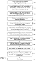
- Pilot positions the aircraft at the beginning of the runway (52).
- Pilot can apply brakes or not, depending on the condition, in order to keep the aircraft from rolling during engine spin up (54).
- Pilot then commands the spin up of the engines, up to the necessary thrust required for that particular take off (56).
- Aircraft starts rolling down the runway and increasing its speed (60).
- Pilot controls directional movement, keeping the airplane aligned with the runway (62).
- pilot shall control aircraft attitude (theta or ⁇ ) up to 35 feet, or a predefined V2, whichever happens first (72).
- V2 is the minimum speed that needs to be maintained up to acceleration altitude, in the event of an engine failure after V1. Flight at V2 ensures that the minimum required climb gradient is achieved, and that the aircraft is controllable.
- the 35 feet screen height marks the end of the takeoff phase of the flight, giving away to the climb phase (74).
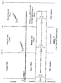
- path 1 depicts a flight path based on a minimum 400 foot level-off for acceleration and flap retraction following the second segment climb portion of the flight path.
- Path 2 depicts the upper limit of the takeoff flight path following an extended second segment. Depending on obstacle clearance needs, the second segment may be extended.
- Ground Roll and Ground Distance From the starting position of the aircraft up to the moment the aircraft lifts off the ground.
- 2nd segment From the end of 1st segment up to the point where the aircraft reaches 400ft above runway level, or the level off altitude, whichever is greater.
- no additional input signals are required to control the aircraft trajectory during the takeoff maneuver.
- the pilot interface is defined using the same concepts applied for standard autopilot operations, using the same controls and annunciations whenever possible. This greatly reduces the possibility of pilot error and therefore allows a seamless incorporation of new functionality.
- the pilot instructs the flight computer of the pilot's desire to perform an automated takeoff through the pilot cockpit interface (e.g., Multi-Function Control Display Unity - MCDU). From there on, the standard takeoff preparation tasks are performed such as flap configuration, vspeeds insertion, horizontal stabilizer positioning and flight director activation.
- the standard takeoff preparation tasks are performed such as flap configuration, vspeeds insertion, horizontal stabilizer positioning and flight director activation.
- the existing takeoff configuration monitor is adapted to verify all necessary conditions for the ETS function and alert the pilot if any is not available.
- Mode and engagement status indications are provided to the crew through a standard flight mode annunciator, along with standard flight director commands for pilot monitoring.
- Pilot inceptors are locked in position in the same way as the standard autopilot to avoid undesired function disengagements, which would occur if any of the inceptors are moved into any direction.
- An objective of example non-limiting implementations is to optimize the longitudinal control surfaces deflection to provide the maximum climb rate to the aircraft.
- FIG. 3 is a schematic block hardware or system component diagram of an overall aircraft control system 100.
- This example non-limiting implementation uses means 102 for measuring air data (e.g., probes), a means of measuring aircraft inertial information comprising an inertial measuring system (e.g., AHRS) for measuring aircraft inertial information 104 and means of processing data and computing outputs 108 (e.g., a conventional flight computer) for computing the longitudinal control surfaces deflection. All of this information is processed in some electronic device such as, but not limited to, a conventional Fly-By-Wire processor 108.
- Such a processor may for example execute instructions stored in non-transitory memory such as a flash or other volatile or non-volatile memory device.
- the processor 108 generates commands which it sends to a means for actuating a flight control system 110 (e.g., a hydraulic or electromechanical actuator) to control the longitudinal control surface 112 such as an elevator 114.
- a flight control system 110 e.g.,
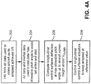
- Figure 4 presents a diagram relating the aircraft 200 and the ETS system 100' and Figure 4A shows a corresponding flowchart.
- Information obtained from the air data 102 is used to rotate the aircraft as its airspeed achieves a pre-defined rotation speed (Vr) ( Fig. 4A block 202).
- Information obtained from the air data 102 and the inertial system 104 are fed back to permit the ETS logic 108' to compute the maximum allowable pitch angle which does not cause the aircraft tail to touch the ground as it rotates and also prevents the aircraft maximum angle of attack to not exceed the aircraft stall limits ( Fig. 4A block 204).
- the ETS control logic 108' computes the necessary longitudinal control surfaces deflection to control the aircraft at this maximum allowable pitch angle up to the aircraft screen height and/or a pre-defined climb speed (V climb ) ( Fig. 4A block 206). From this point, the system controls the longitudinal control surface actuators 110 to keep the airspeed at another reference value (e. g., V 2 , V climb , etc.) ( Fig. 4A block 208).
- V climb a pre-defined climb speed
- the non-limiting example technology herein includes an additional control loop shown in Fig. 5 which proposes for the lateral axis to use the lateral control surfaces to maintain the aircraft wing leveled during the ground roll segment ( Fig. 5A block 302).
- the example non-limiting embodiment commands the aircraft 200 to the bank angle in which the best take-off performance is achieved, limiting the bank angle to avoid the wing tips hitting the ground ( Fig. 5A block 304).
- the system computes the directional control surfaces deflection in order to provide for the aircraft some level of augmented stability and controllability during the ground roll segment (block 302).
- the ETS logic 108 computes directional control surface deflection and commands in order to provide suitable stability and flight quality in the pursuit of the sideslip in which the best take-off performance is achieved (block 306).
- inertial signals e.g., Inertial System 104
- air data signal e.g., probes
- the avionics sends a signal to the Primary Flight Display PFD with the value of a pre-calculated optimum Beta angle that reduces drag for a given speed.
- the proposed non-limiting features provide means through which the aircraft can automatically follow a predetermined (tabulated) set of Beta and Phi values from the very first moment after the aircraft lifts off the ground, using a given control law architecture.
- the proposed control law senses aircraft attitude and accelerations through sensors. It then computes the amount of command necessary to pursue these Beta and Phi values, sending signals to the control surfaces actuators.
- the automatic control law then controls these surface deflections in order to precisely track the pre-determined optimum values of Beta and Phi.
- Affected control surfaces are the ones responsible for YAW and ROLL movements, which could be, but not limited to:
- Fig. 6 shows example forces acting on aircraft 200.
- Fig. 7 shows new pitch and speed control and lateral wings level functionality of the example non-limiting ETS system augmenting the basic preexisting fly-by-way (FBW) functionality to provide wings level and/or wings level/bank angle for best performance.
- FBW fly-by-way
Landscapes
- Engineering & Computer Science (AREA)
- Aviation & Aerospace Engineering (AREA)
- Automation & Control Theory (AREA)
- Radar, Positioning & Navigation (AREA)
- Remote Sensing (AREA)
- Physics & Mathematics (AREA)
- General Physics & Mathematics (AREA)
- Control Of Position, Course, Altitude, Or Attitude Of Moving Bodies (AREA)
- Traffic Control Systems (AREA)
- Catching Or Destruction (AREA)
Claims (11)
- Système de décollage automatique comprenant :au moins un capteur de mesure de données aérodynamiques ;au moins un capteur inertiel ; etau moins un processeur, couplé au capteur de mesure de données aérodynamiques et au capteur inertiel, ledit au moins un processeur accédant aux vitesses de décollage « VR » et « V2 » en vue de fournir une commande de gouvernes à la fois longitudinale et latérale-directionnelle afin d'assurer le décollage automatique d'un aéronef ;caractérisé en ce que :
ledit au moins un processeur est configuré de manière à commander l'aéronef à un angle d'inclinaison dans lequel une performance de décollage optimale est atteinte, et à limiter l'angle d'inclinaison pour éviter que les extrémités des ailes ne heurtent le sol. - Système de décollage automatique selon la revendication 1, dans lequel ledit au moins un processeur comprend des commandes de vol électriques.
- Système de décollage automatique selon la revendication 1 ou 2, dans lequel ledit au moins un processeur calcule un braquage de gouverne longitudinal nécessaire pour contrôler le tangage maximal admissible de l'aéronef jusqu'à la hauteur d'écran d'aéronef et/ou une vitesse de montée prédéfinie.
- Système de décollage automatique selon l'une quelconque des revendications précédentes, dans lequel ledit au moins un processeur commande des actionneurs de gouvernes longitudinales pour maintenir une vitesse à un niveau de référence lorsqu'il est détecté que l'aéronef a atteint la vitesse de montée prédéfinie.
- Système de décollage automatique selon l'une quelconque des revendications précédentes, dans lequel ledit au moins un processeur commande des gouvernes latérales pour maintenir une aile d'aéronef à l'horizontale pendant un segment de roulage au sol.
- Système de décollage automatique selon l'une quelconque des revendications précédentes, dans lequel ledit au moins un processeur calcule un braquage de gouverne directionnel afin d'augmenter la stabilité et la contrôlabilité pendant un segment de roulage au sol.
- Système de décollage automatique selon l'une quelconque des revendications précédentes, dans lequel le système réduit une distance de décollage et/ou permet d'augmenter un poids au décollage.
- Système de décollage automatique selon l'une quelconque des revendications précédentes, dans lequel ledit au moins un processeur règle un stabilisateur horizontal dans une condition non compensée afin de fournir une compensation en tangage qui aide l'aéronef à atteindre la performance de décollage la plus optimale sous l'effet d'une vitesse angulaire de tangage plus élevée.
- Système de décollage automatique selon l'une quelconque des revendications précédentes, dans lequel ledit au moins un processeur fournit conditionnellement une indication bêta optimale pour minimiser une traînée aérodynamique, dans lequel le train d'atterrissage n'est pas verrouillé en position basse, les manettes de poussée sont en configuration de décollage, et les volets sont en position de décollage, et fournit également une valeur Bêta et Phi prédéterminée qui commence lorsque l'aéronef décolle du sol.
- Système de décollage automatique selon l'une quelconque des revendications précédentes, dans lequel le système fournit une réduction de traînée asymétrique au décollage en contrôlant les gouvernes responsables du lacet et du roulis, y compris, mais sans s'y limiter, les ailerons, la gouverne de direction, les spoilers, les spoilers de gauchissement, ou spoilerons, les élevons et les flaperons.
- Mémoire non transitoire lisible par ordinateur incluant des instructions qui, lorsqu'elles sont exécutées par un processeur à bord d'un aéronef, commandent le processeur pour mettre en œuvre des fonctions incluant les étapes ci-dessous consistant à :commander l'angle d'inclinaison de l'aéronef pour atteindre une performance de décollage optimale, tout en limitant l'angle d'inclinaison pour éviter de heurter les extrémités des ailes ; etcalculer un braquage de gouverne directionnel et des commandes pour assurer une stabilité et une qualité de vol appropriées pour un glissement sur l'aile avec une performance de décollage optimale.
Applications Claiming Priority (1)
| Application Number | Priority Date | Filing Date | Title |
|---|---|---|---|
| US15/273,986 US11226639B2 (en) | 2016-09-23 | 2016-09-23 | Enhanced take-off system |
Publications (3)
| Publication Number | Publication Date |
|---|---|
| EP3299924A2 EP3299924A2 (fr) | 2018-03-28 |
| EP3299924A3 EP3299924A3 (fr) | 2018-09-05 |
| EP3299924B1 true EP3299924B1 (fr) | 2020-08-26 |
Family
ID=59858575
Family Applications (1)
| Application Number | Title | Priority Date | Filing Date |
|---|---|---|---|
| EP17190574.8A Active EP3299924B1 (fr) | 2016-09-23 | 2017-09-12 | Système de décollage amélioré |
Country Status (4)
| Country | Link |
|---|---|
| US (1) | US11226639B2 (fr) |
| EP (1) | EP3299924B1 (fr) |
| CN (1) | CN107870629B (fr) |
| BR (1) | BR102017020139A2 (fr) |
Families Citing this family (8)
| Publication number | Priority date | Publication date | Assignee | Title |
|---|---|---|---|---|
| FR3065543B1 (fr) * | 2017-04-19 | 2019-05-03 | Airbus Operations (S.A.S.) | Calculateur de commande de vol d'un aeronef |
| CN109782795B (zh) * | 2018-12-29 | 2020-07-07 | 南京航空航天大学 | 一种利用耦合的面对称高超声速飞行器横侧向控制方法及控制系统 |
| GB2583464A (en) * | 2019-04-18 | 2020-11-04 | Airbus Operations Ltd | System and method for landing gear retraction |
| US11837099B2 (en) | 2019-11-22 | 2023-12-05 | Ge Aviation Systems Limited | Aircraft flight management system |
| US11841713B2 (en) * | 2020-01-07 | 2023-12-12 | Gulfstream Aerospace Corporation | Controllers and aircraft with takeoff stall protection system |
| US20210405658A1 (en) | 2020-06-25 | 2021-12-30 | Embraer S.A. | Longitudinal trim control movement during takeoff rotation |
| EP4190701A1 (fr) * | 2021-11-30 | 2023-06-07 | Airbus SAS | Avertissement de rotation |
| CN116090097A (zh) * | 2022-12-30 | 2023-05-09 | 北京机电工程研究所 | 基于等效撞水设计的近水面流固耦合有限元高效计算方法 |
Family Cites Families (27)
| Publication number | Priority date | Publication date | Assignee | Title |
|---|---|---|---|---|
| US3681580A (en) | 1969-08-01 | 1972-08-01 | Teledyne Inc | Rotation,climbout,and go-around control system |
| US3822047A (en) | 1972-12-14 | 1974-07-02 | Collins Radio Co | Takeoff and go-around climb-out profile pitch command formulation for aircraft |
| US3945590A (en) | 1975-01-23 | 1976-03-23 | Sperry Rand Corporation | Semi-automatic takeoff control system for aircraft |
| US4676460A (en) * | 1984-11-28 | 1987-06-30 | The Boeing Company | Longitudinal stability augmentation system and method |
| FR2711257B1 (fr) | 1993-10-14 | 1995-12-22 | Aerospatiale | Système de commande de vol électrique pour avion avec protection en assiette au décollage. |
| US6422517B1 (en) | 1999-12-02 | 2002-07-23 | Boeing Company | Aircraft tailstrike avoidance system |
| FR2817535B1 (fr) * | 2000-12-06 | 2003-03-21 | Eads Airbus Sa | Systeme pour commander automatiquement des dispositifs hypersustentateurs d'un aeronef durant le decollage |
| FR2826469B1 (fr) | 2001-06-25 | 2003-10-24 | Eads Airbus Sa | Procede et dispositif pour commander au moins une surface aerodynamique de profondeur d'un avion lors d'un decollage |
| JP4328660B2 (ja) * | 2004-04-15 | 2009-09-09 | 富士重工業株式会社 | 航空機の自動離陸装置、自動着陸装置及び自動離着陸装置並びに航空機の自動離陸方法、自動着陸方法及び自動離着陸方法 |
| FR2869588B1 (fr) | 2004-04-28 | 2006-07-14 | Airbus France Sas | Procede d'aide au decollage d'un aeronef. |
| FR2885706B1 (fr) * | 2005-05-10 | 2007-06-15 | Airbus France Sas | Procede d'aide au decollage d'un aeronef. |
| FR2894045B1 (fr) * | 2005-11-28 | 2008-02-15 | Airbus France Sas | Procede de controle de parametres de decollage ou d'atterrissage et dispositif associe |
| FR2909461B1 (fr) * | 2006-12-05 | 2014-08-22 | Airbus France | Procede et dispositif de decollage automatique d'un avion. |
| GB2446405B (en) | 2007-02-09 | 2011-07-27 | David Lawson | Airfoils with automatic pitch control |
| FR2929723B1 (fr) * | 2008-04-02 | 2011-02-11 | Airbus France | Procede pour la reduction exceptionnelle de la course d'envol d'un aeronef. |
| FR2942612B1 (fr) * | 2009-03-02 | 2012-09-28 | Airbus France | Procede et dispositif d'optimisation automatique au sol de la configuration aerodynamique d'un avion |
| US20110040431A1 (en) * | 2009-08-11 | 2011-02-17 | Honeywell International Inc. | Automated take off control system and method |
| US8793040B2 (en) * | 2011-06-10 | 2014-07-29 | Embraer S.A. | Climb-optimized auto takeoff system |
| FR2986065B1 (fr) | 2012-01-23 | 2015-04-17 | Airbus Operations Sas | Procede et dispositif d'affichage d'informations d'assiette sur un avion lors d'un decollage. |
| IL222053A (en) * | 2012-09-23 | 2016-11-30 | Israel Aerospace Ind Ltd | A device, method, and computerized product for aircraft management |
| US9359065B2 (en) * | 2013-09-24 | 2016-06-07 | The Boeing Company | System and method for optimizing performance of an aircraft |
| CN104536455B (zh) * | 2014-12-15 | 2017-02-01 | 中国航空工业经济技术研究院 | 一种实现飞行体验功能的无人通用飞机飞行控制方法 |
| CN105005342B (zh) * | 2015-08-11 | 2017-06-16 | 中国航空工业集团公司西安飞机设计研究所 | 控制飞行器自动起飞的方法 |
| US9696724B1 (en) * | 2016-04-22 | 2017-07-04 | Rockwell Collins, Inc. | Takeoff automating system, device, and method |
| FR3052251B1 (fr) * | 2016-06-03 | 2018-05-18 | Airbus Operations (S.A.S.) | Procede d'optimisation des parametres de decollage d'un aeronef |
| US10479481B2 (en) * | 2016-09-28 | 2019-11-19 | The Boeing Company | Process and machine for reducing a drag component of a horizontal stabilizer on an aircraft |
| US10816998B2 (en) * | 2017-09-18 | 2020-10-27 | The Boeing Company | Airplane takeoff trims utilizing both stabilizers and elevators |
-
2016
- 2016-09-23 US US15/273,986 patent/US11226639B2/en active Active
-
2017
- 2017-09-12 EP EP17190574.8A patent/EP3299924B1/fr active Active
- 2017-09-20 CN CN201710852674.8A patent/CN107870629B/zh active Active
- 2017-09-20 BR BR102017020139-2A patent/BR102017020139A2/pt active IP Right Grant
Non-Patent Citations (1)
| Title |
|---|
| None * |
Also Published As
| Publication number | Publication date |
|---|---|
| BR102017020139A2 (pt) | 2018-05-02 |
| EP3299924A2 (fr) | 2018-03-28 |
| CN107870629B (zh) | 2023-01-31 |
| US20180088593A1 (en) | 2018-03-29 |
| EP3299924A3 (fr) | 2018-09-05 |
| CN107870629A (zh) | 2018-04-03 |
| US11226639B2 (en) | 2022-01-18 |
Similar Documents
| Publication | Publication Date | Title |
|---|---|---|
| EP3299924B1 (fr) | Système de décollage amélioré | |
| EP2635942B1 (fr) | Lois de commande de vol pour commande de trajectoire de vol vertical | |
| EP2787408B1 (fr) | Guidage d'approche finale | |
| US9472107B2 (en) | Method and device for determining a control set point of an aircraft, associated computer program and aircraft | |
| EP3037345B1 (fr) | Procédé de contrôle automatique de la phase de descente d'un avion à l'aide d'une avionique exécutant un algorithme de descente | |
| EP3208680A1 (fr) | Systèmes et procédés pour empêcher la queue d'un aéronef d'entrer en contact avec le sol | |
| US11054437B2 (en) | Method and system for aircraft sideslip guidance | |
| EP3159767B1 (fr) | Système de prévention de montée verticale pour une performance améliorée | |
| JP2016164060A5 (fr) | ||
| EP3929073A1 (fr) | Contrôle de l'assiette longitudinale pendant la rotation de décollage | |
| Zollitsch et al. | Automatic takeoff of a general aviation research aircraft | |
| EP3848289A1 (fr) | Organes de commande et aéronef doté d'un système de protection contre le décrochage au décollage | |
| Mumm et al. | Design and testing of a ground roll runway centerline tracking controller for a general aviation research aircraft | |
| Burcham, Jr et al. | Development and flight test of an augmented thrust-only flight control system on an MD-11 transport airplane | |
| O'hara | Stability augmentation in aircraft design | |
| US11001376B2 (en) | Precision pointing mode of an aircraft | |
| Shweyk et al. | Validation of the Flight Control System of a Conceptual, Powered-Lift, Speed-Agile, Transport Aircraft | |
| Sadraey | Flight Path Control Systems | |
| Last | A320 and B757 on the Liner: A Line Pilot's Perspective | |
| DORR et al. | Simulation and flight test evaluation of head-up-display guidance for Harrier approach transitions | |
| WATSON et al. | Flight evaluation of a precision landing task for a powered-lift STOL aircraft | |
| Reel | A Flight Simulation Study of the Simultaneous Non Interfering Aircraft Approach | |
| Didenko et al. | The specific features of FBW control laws of advanced regional jet | |
| DONIGER | Some automatic landing system design considerations for scheduled operations | |
| Miller | Recent flight control system developments for takeoff, approach-landing and missed-approach |
Legal Events
| Date | Code | Title | Description |
|---|---|---|---|
| PUAI | Public reference made under article 153(3) epc to a published international application that has entered the european phase |
Free format text: ORIGINAL CODE: 0009012 |
|
| STAA | Information on the status of an ep patent application or granted ep patent |
Free format text: STATUS: THE APPLICATION HAS BEEN PUBLISHED |
|
| AK | Designated contracting states |
Kind code of ref document: A2 Designated state(s): AL AT BE BG CH CY CZ DE DK EE ES FI FR GB GR HR HU IE IS IT LI LT LU LV MC MK MT NL NO PL PT RO RS SE SI SK SM TR |
|
| AX | Request for extension of the european patent |
Extension state: BA ME |
|
| RIC1 | Information provided on ipc code assigned before grant |
Ipc: G05D 1/06 20060101AFI20180425BHEP |
|
| PUAL | Search report despatched |
Free format text: ORIGINAL CODE: 0009013 |
|
| AK | Designated contracting states |
Kind code of ref document: A3 Designated state(s): AL AT BE BG CH CY CZ DE DK EE ES FI FR GB GR HR HU IE IS IT LI LT LU LV MC MK MT NL NO PL PT RO RS SE SI SK SM TR |
|
| AX | Request for extension of the european patent |
Extension state: BA ME |
|
| RIC1 | Information provided on ipc code assigned before grant |
Ipc: G05D 1/06 20060101AFI20180730BHEP |
|
| STAA | Information on the status of an ep patent application or granted ep patent |
Free format text: STATUS: REQUEST FOR EXAMINATION WAS MADE |
|
| 17P | Request for examination filed |
Effective date: 20190301 |
|
| RBV | Designated contracting states (corrected) |
Designated state(s): AL AT BE BG CH CY CZ DE DK EE ES FI FR GB GR HR HU IE IS IT LI LT LU LV MC MK MT NL NO PL PT RO RS SE SI SK SM TR |
|
| RIN1 | Information on inventor provided before grant (corrected) |
Inventor name: CARNEIRO, LUIZ GUSTAVO MEDEIROS Inventor name: DE CAMARGO CLARK REIS, JOSE ROBERTO FERREIRA Inventor name: GUEDES, PATRICE LONDON Inventor name: KESTENBACH, THOMAS Inventor name: DE TARSO FERREIRA, DANIEL PAULO |
|
| STAA | Information on the status of an ep patent application or granted ep patent |
Free format text: STATUS: EXAMINATION IS IN PROGRESS |
|
| 17Q | First examination report despatched |
Effective date: 20190425 |
|
| GRAP | Despatch of communication of intention to grant a patent |
Free format text: ORIGINAL CODE: EPIDOSNIGR1 |
|
| STAA | Information on the status of an ep patent application or granted ep patent |
Free format text: STATUS: GRANT OF PATENT IS INTENDED |
|
| INTG | Intention to grant announced |
Effective date: 20200319 |
|
| RAP1 | Party data changed (applicant data changed or rights of an application transferred) |
Owner name: YABORA INDUSTRIA AERONAUTICA S.A. |
|
| GRAS | Grant fee paid |
Free format text: ORIGINAL CODE: EPIDOSNIGR3 |
|
| GRAA | (expected) grant |
Free format text: ORIGINAL CODE: 0009210 |
|
| STAA | Information on the status of an ep patent application or granted ep patent |
Free format text: STATUS: THE PATENT HAS BEEN GRANTED |
|
| AK | Designated contracting states |
Kind code of ref document: B1 Designated state(s): AL AT BE BG CH CY CZ DE DK EE ES FI FR GB GR HR HU IE IS IT LI LT LU LV MC MK MT NL NO PL PT RO RS SE SI SK SM TR |
|
| REG | Reference to a national code |
Ref country code: GB Ref legal event code: FG4D |
|
| REG | Reference to a national code |
Ref country code: CH Ref legal event code: EP |
|
| REG | Reference to a national code |
Ref country code: AT Ref legal event code: REF Ref document number: 1306955 Country of ref document: AT Kind code of ref document: T Effective date: 20200915 |
|
| REG | Reference to a national code |
Ref country code: IE Ref legal event code: FG4D |
|
| REG | Reference to a national code |
Ref country code: DE Ref legal event code: R096 Ref document number: 602017022255 Country of ref document: DE |
|
| REG | Reference to a national code |
Ref country code: LT Ref legal event code: MG4D |
|
| PG25 | Lapsed in a contracting state [announced via postgrant information from national office to epo] |
Ref country code: FI Free format text: LAPSE BECAUSE OF FAILURE TO SUBMIT A TRANSLATION OF THE DESCRIPTION OR TO PAY THE FEE WITHIN THE PRESCRIBED TIME-LIMIT Effective date: 20200826 Ref country code: NO Free format text: LAPSE BECAUSE OF FAILURE TO SUBMIT A TRANSLATION OF THE DESCRIPTION OR TO PAY THE FEE WITHIN THE PRESCRIBED TIME-LIMIT Effective date: 20201126 Ref country code: LT Free format text: LAPSE BECAUSE OF FAILURE TO SUBMIT A TRANSLATION OF THE DESCRIPTION OR TO PAY THE FEE WITHIN THE PRESCRIBED TIME-LIMIT Effective date: 20200826 Ref country code: HR Free format text: LAPSE BECAUSE OF FAILURE TO SUBMIT A TRANSLATION OF THE DESCRIPTION OR TO PAY THE FEE WITHIN THE PRESCRIBED TIME-LIMIT Effective date: 20200826 Ref country code: BG Free format text: LAPSE BECAUSE OF FAILURE TO SUBMIT A TRANSLATION OF THE DESCRIPTION OR TO PAY THE FEE WITHIN THE PRESCRIBED TIME-LIMIT Effective date: 20201126 Ref country code: SE Free format text: LAPSE BECAUSE OF FAILURE TO SUBMIT A TRANSLATION OF THE DESCRIPTION OR TO PAY THE FEE WITHIN THE PRESCRIBED TIME-LIMIT Effective date: 20200826 Ref country code: PT Free format text: LAPSE BECAUSE OF FAILURE TO SUBMIT A TRANSLATION OF THE DESCRIPTION OR TO PAY THE FEE WITHIN THE PRESCRIBED TIME-LIMIT Effective date: 20201228 |
|
| REG | Reference to a national code |
Ref country code: NL Ref legal event code: MP Effective date: 20200826 |
|
| REG | Reference to a national code |
Ref country code: AT Ref legal event code: MK05 Ref document number: 1306955 Country of ref document: AT Kind code of ref document: T Effective date: 20200826 |
|
| PG25 | Lapsed in a contracting state [announced via postgrant information from national office to epo] |
Ref country code: PL Free format text: LAPSE BECAUSE OF FAILURE TO SUBMIT A TRANSLATION OF THE DESCRIPTION OR TO PAY THE FEE WITHIN THE PRESCRIBED TIME-LIMIT Effective date: 20200826 Ref country code: NL Free format text: LAPSE BECAUSE OF FAILURE TO SUBMIT A TRANSLATION OF THE DESCRIPTION OR TO PAY THE FEE WITHIN THE PRESCRIBED TIME-LIMIT Effective date: 20200826 Ref country code: RS Free format text: LAPSE BECAUSE OF FAILURE TO SUBMIT A TRANSLATION OF THE DESCRIPTION OR TO PAY THE FEE WITHIN THE PRESCRIBED TIME-LIMIT Effective date: 20200826 Ref country code: LV Free format text: LAPSE BECAUSE OF FAILURE TO SUBMIT A TRANSLATION OF THE DESCRIPTION OR TO PAY THE FEE WITHIN THE PRESCRIBED TIME-LIMIT Effective date: 20200826 Ref country code: IS Free format text: LAPSE BECAUSE OF FAILURE TO SUBMIT A TRANSLATION OF THE DESCRIPTION OR TO PAY THE FEE WITHIN THE PRESCRIBED TIME-LIMIT Effective date: 20201226 |
|
| PG25 | Lapsed in a contracting state [announced via postgrant information from national office to epo] |
Ref country code: SM Free format text: LAPSE BECAUSE OF FAILURE TO SUBMIT A TRANSLATION OF THE DESCRIPTION OR TO PAY THE FEE WITHIN THE PRESCRIBED TIME-LIMIT Effective date: 20200826 Ref country code: EE Free format text: LAPSE BECAUSE OF FAILURE TO SUBMIT A TRANSLATION OF THE DESCRIPTION OR TO PAY THE FEE WITHIN THE PRESCRIBED TIME-LIMIT Effective date: 20200826 Ref country code: RO Free format text: LAPSE BECAUSE OF FAILURE TO SUBMIT A TRANSLATION OF THE DESCRIPTION OR TO PAY THE FEE WITHIN THE PRESCRIBED TIME-LIMIT Effective date: 20200826 Ref country code: DK Free format text: LAPSE BECAUSE OF FAILURE TO SUBMIT A TRANSLATION OF THE DESCRIPTION OR TO PAY THE FEE WITHIN THE PRESCRIBED TIME-LIMIT Effective date: 20200826 Ref country code: CZ Free format text: LAPSE BECAUSE OF FAILURE TO SUBMIT A TRANSLATION OF THE DESCRIPTION OR TO PAY THE FEE WITHIN THE PRESCRIBED TIME-LIMIT Effective date: 20200826 |
|
| REG | Reference to a national code |
Ref country code: CH Ref legal event code: PL |
|
| REG | Reference to a national code |
Ref country code: DE Ref legal event code: R097 Ref document number: 602017022255 Country of ref document: DE |
|
| PG25 | Lapsed in a contracting state [announced via postgrant information from national office to epo] |
Ref country code: AT Free format text: LAPSE BECAUSE OF FAILURE TO SUBMIT A TRANSLATION OF THE DESCRIPTION OR TO PAY THE FEE WITHIN THE PRESCRIBED TIME-LIMIT Effective date: 20200826 Ref country code: AL Free format text: LAPSE BECAUSE OF FAILURE TO SUBMIT A TRANSLATION OF THE DESCRIPTION OR TO PAY THE FEE WITHIN THE PRESCRIBED TIME-LIMIT Effective date: 20200826 Ref country code: ES Free format text: LAPSE BECAUSE OF FAILURE TO SUBMIT A TRANSLATION OF THE DESCRIPTION OR TO PAY THE FEE WITHIN THE PRESCRIBED TIME-LIMIT Effective date: 20200826 Ref country code: MC Free format text: LAPSE BECAUSE OF FAILURE TO SUBMIT A TRANSLATION OF THE DESCRIPTION OR TO PAY THE FEE WITHIN THE PRESCRIBED TIME-LIMIT Effective date: 20200826 |
|
| REG | Reference to a national code |
Ref country code: BE Ref legal event code: MM Effective date: 20200930 |
|
| PG25 | Lapsed in a contracting state [announced via postgrant information from national office to epo] |
Ref country code: SK Free format text: LAPSE BECAUSE OF FAILURE TO SUBMIT A TRANSLATION OF THE DESCRIPTION OR TO PAY THE FEE WITHIN THE PRESCRIBED TIME-LIMIT Effective date: 20200826 Ref country code: LU Free format text: LAPSE BECAUSE OF NON-PAYMENT OF DUE FEES Effective date: 20200912 |
|
| PLBE | No opposition filed within time limit |
Free format text: ORIGINAL CODE: 0009261 |
|
| STAA | Information on the status of an ep patent application or granted ep patent |
Free format text: STATUS: NO OPPOSITION FILED WITHIN TIME LIMIT |
|
| PG25 | Lapsed in a contracting state [announced via postgrant information from national office to epo] |
Ref country code: IT Free format text: LAPSE BECAUSE OF FAILURE TO SUBMIT A TRANSLATION OF THE DESCRIPTION OR TO PAY THE FEE WITHIN THE PRESCRIBED TIME-LIMIT Effective date: 20200826 |
|
| 26N | No opposition filed |
Effective date: 20210527 |
|
| PG25 | Lapsed in a contracting state [announced via postgrant information from national office to epo] |
Ref country code: LI Free format text: LAPSE BECAUSE OF NON-PAYMENT OF DUE FEES Effective date: 20200930 Ref country code: IE Free format text: LAPSE BECAUSE OF NON-PAYMENT OF DUE FEES Effective date: 20200912 Ref country code: SI Free format text: LAPSE BECAUSE OF FAILURE TO SUBMIT A TRANSLATION OF THE DESCRIPTION OR TO PAY THE FEE WITHIN THE PRESCRIBED TIME-LIMIT Effective date: 20200826 Ref country code: BE Free format text: LAPSE BECAUSE OF NON-PAYMENT OF DUE FEES Effective date: 20200930 Ref country code: CH Free format text: LAPSE BECAUSE OF NON-PAYMENT OF DUE FEES Effective date: 20200930 |
|
| GBPC | Gb: european patent ceased through non-payment of renewal fee |
Effective date: 20210912 |
|
| PG25 | Lapsed in a contracting state [announced via postgrant information from national office to epo] |
Ref country code: TR Free format text: LAPSE BECAUSE OF FAILURE TO SUBMIT A TRANSLATION OF THE DESCRIPTION OR TO PAY THE FEE WITHIN THE PRESCRIBED TIME-LIMIT Effective date: 20200826 Ref country code: MT Free format text: LAPSE BECAUSE OF FAILURE TO SUBMIT A TRANSLATION OF THE DESCRIPTION OR TO PAY THE FEE WITHIN THE PRESCRIBED TIME-LIMIT Effective date: 20200826 Ref country code: CY Free format text: LAPSE BECAUSE OF FAILURE TO SUBMIT A TRANSLATION OF THE DESCRIPTION OR TO PAY THE FEE WITHIN THE PRESCRIBED TIME-LIMIT Effective date: 20200826 |
|
| PG25 | Lapsed in a contracting state [announced via postgrant information from national office to epo] |
Ref country code: MK Free format text: LAPSE BECAUSE OF FAILURE TO SUBMIT A TRANSLATION OF THE DESCRIPTION OR TO PAY THE FEE WITHIN THE PRESCRIBED TIME-LIMIT Effective date: 20200826 |
|
| PG25 | Lapsed in a contracting state [announced via postgrant information from national office to epo] |
Ref country code: GR Free format text: LAPSE BECAUSE OF FAILURE TO SUBMIT A TRANSLATION OF THE DESCRIPTION OR TO PAY THE FEE WITHIN THE PRESCRIBED TIME-LIMIT Effective date: 20200826 Ref country code: GB Free format text: LAPSE BECAUSE OF NON-PAYMENT OF DUE FEES Effective date: 20210912 |
|
| REG | Reference to a national code |
Ref country code: DE Ref legal event code: R079 Ref document number: 602017022255 Country of ref document: DE Free format text: PREVIOUS MAIN CLASS: G05D0001060000 Ipc: G05D0001485000 |
|
| PGFP | Annual fee paid to national office [announced via postgrant information from national office to epo] |
Ref country code: FR Payment date: 20230911 Year of fee payment: 7 Ref country code: DE Payment date: 20230929 Year of fee payment: 7 |