EP3299748A1 - Electric valve control device and electric valve device including the same - Google Patents
Electric valve control device and electric valve device including the same Download PDFInfo
- Publication number
- EP3299748A1 EP3299748A1 EP17192271.9A EP17192271A EP3299748A1 EP 3299748 A1 EP3299748 A1 EP 3299748A1 EP 17192271 A EP17192271 A EP 17192271A EP 3299748 A1 EP3299748 A1 EP 3299748A1
- Authority
- EP
- European Patent Office
- Prior art keywords
- electric valve
- initialization operation
- control device
- pulses
- initialization
- Prior art date
- Legal status (The legal status is an assumption and is not a legal conclusion. Google has not performed a legal analysis and makes no representation as to the accuracy of the status listed.)
- Granted
Links
Images


Classifications
-
- F—MECHANICAL ENGINEERING; LIGHTING; HEATING; WEAPONS; BLASTING
- F16—ENGINEERING ELEMENTS AND UNITS; GENERAL MEASURES FOR PRODUCING AND MAINTAINING EFFECTIVE FUNCTIONING OF MACHINES OR INSTALLATIONS; THERMAL INSULATION IN GENERAL
- F16K—VALVES; TAPS; COCKS; ACTUATING-FLOATS; DEVICES FOR VENTING OR AERATING
- F16K31/00—Actuating devices; Operating means; Releasing devices
- F16K31/02—Actuating devices; Operating means; Releasing devices electric; magnetic
- F16K31/04—Actuating devices; Operating means; Releasing devices electric; magnetic using a motor
-
- F—MECHANICAL ENGINEERING; LIGHTING; HEATING; WEAPONS; BLASTING
- F25—REFRIGERATION OR COOLING; COMBINED HEATING AND REFRIGERATION SYSTEMS; HEAT PUMP SYSTEMS; MANUFACTURE OR STORAGE OF ICE; LIQUEFACTION SOLIDIFICATION OF GASES
- F25B—REFRIGERATION MACHINES, PLANTS OR SYSTEMS; COMBINED HEATING AND REFRIGERATION SYSTEMS; HEAT PUMP SYSTEMS
- F25B41/00—Fluid-circulation arrangements
- F25B41/30—Expansion means; Dispositions thereof
- F25B41/31—Expansion valves
- F25B41/34—Expansion valves with the valve member being actuated by electric means, e.g. by piezoelectric actuators
- F25B41/35—Expansion valves with the valve member being actuated by electric means, e.g. by piezoelectric actuators by rotary motors, e.g. by stepping motors
-
- F—MECHANICAL ENGINEERING; LIGHTING; HEATING; WEAPONS; BLASTING
- F16—ENGINEERING ELEMENTS AND UNITS; GENERAL MEASURES FOR PRODUCING AND MAINTAINING EFFECTIVE FUNCTIONING OF MACHINES OR INSTALLATIONS; THERMAL INSULATION IN GENERAL
- F16K—VALVES; TAPS; COCKS; ACTUATING-FLOATS; DEVICES FOR VENTING OR AERATING
- F16K11/00—Multiple-way valves, e.g. mixing valves; Pipe fittings incorporating such valves
- F16K11/10—Multiple-way valves, e.g. mixing valves; Pipe fittings incorporating such valves with two or more closure members not moving as a unit
- F16K11/105—Three-way check or safety valves with two or more closure members
-
- F—MECHANICAL ENGINEERING; LIGHTING; HEATING; WEAPONS; BLASTING
- F16—ENGINEERING ELEMENTS AND UNITS; GENERAL MEASURES FOR PRODUCING AND MAINTAINING EFFECTIVE FUNCTIONING OF MACHINES OR INSTALLATIONS; THERMAL INSULATION IN GENERAL
- F16K—VALVES; TAPS; COCKS; ACTUATING-FLOATS; DEVICES FOR VENTING OR AERATING
- F16K31/00—Actuating devices; Operating means; Releasing devices
- F16K31/02—Actuating devices; Operating means; Releasing devices electric; magnetic
- F16K31/04—Actuating devices; Operating means; Releasing devices electric; magnetic using a motor
- F16K31/041—Actuating devices; Operating means; Releasing devices electric; magnetic using a motor for rotating valves
- F16K31/042—Actuating devices; Operating means; Releasing devices electric; magnetic using a motor for rotating valves with electric means, e.g. for controlling the motor or a clutch between the valve and the motor
-
- F—MECHANICAL ENGINEERING; LIGHTING; HEATING; WEAPONS; BLASTING
- F25—REFRIGERATION OR COOLING; COMBINED HEATING AND REFRIGERATION SYSTEMS; HEAT PUMP SYSTEMS; MANUFACTURE OR STORAGE OF ICE; LIQUEFACTION SOLIDIFICATION OF GASES
- F25B—REFRIGERATION MACHINES, PLANTS OR SYSTEMS; COMBINED HEATING AND REFRIGERATION SYSTEMS; HEAT PUMP SYSTEMS
- F25B49/00—Arrangement or mounting of control or safety devices
- F25B49/02—Arrangement or mounting of control or safety devices for compression type machines, plants or systems
-
- G—PHYSICS
- G05—CONTROLLING; REGULATING
- G05D—SYSTEMS FOR CONTROLLING OR REGULATING NON-ELECTRIC VARIABLES
- G05D23/00—Control of temperature
- G05D23/19—Control of temperature characterised by the use of electric means
- G05D23/1919—Control of temperature characterised by the use of electric means characterised by the type of controller
-
- G—PHYSICS
- G05—CONTROLLING; REGULATING
- G05F—SYSTEMS FOR REGULATING ELECTRIC OR MAGNETIC VARIABLES
- G05F1/00—Automatic systems in which deviations of an electric quantity from one or more predetermined values are detected at the output of the system and fed back to a device within the system to restore the detected quantity to its predetermined value or values, i.e. retroactive systems
- G05F1/10—Regulating voltage or current
- G05F1/46—Regulating voltage or current wherein the variable actually regulated by the final control device is DC
- G05F1/462—Regulating voltage or current wherein the variable actually regulated by the final control device is DC as a function of the requirements of the load, e.g. delay, temperature, specific voltage/current characteristic
- G05F1/463—Sources providing an output which depends on temperature
-
- G—PHYSICS
- G08—SIGNALLING
- G08B—SIGNALLING SYSTEMS, e.g. PERSONAL CALLING SYSTEMS; ORDER TELEGRAPHS; ALARM SYSTEMS
- G08B1/00—Systems for signalling characterised solely by the form of transmission of the signal
- G08B1/08—Systems for signalling characterised solely by the form of transmission of the signal using electric transmission ; transformation of alarm signals to electrical signals from a different medium, e.g. transmission of an electric alarm signal upon detection of an audible alarm signal
-
- F—MECHANICAL ENGINEERING; LIGHTING; HEATING; WEAPONS; BLASTING
- F25—REFRIGERATION OR COOLING; COMBINED HEATING AND REFRIGERATION SYSTEMS; HEAT PUMP SYSTEMS; MANUFACTURE OR STORAGE OF ICE; LIQUEFACTION SOLIDIFICATION OF GASES
- F25B—REFRIGERATION MACHINES, PLANTS OR SYSTEMS; COMBINED HEATING AND REFRIGERATION SYSTEMS; HEAT PUMP SYSTEMS
- F25B1/00—Compression machines, plants or systems with non-reversible cycle
- F25B1/06—Compression machines, plants or systems with non-reversible cycle with compressor of jet type, e.g. using liquid under pressure
- F25B1/08—Compression machines, plants or systems with non-reversible cycle with compressor of jet type, e.g. using liquid under pressure using vapour under pressure
-
- F—MECHANICAL ENGINEERING; LIGHTING; HEATING; WEAPONS; BLASTING
- F25—REFRIGERATION OR COOLING; COMBINED HEATING AND REFRIGERATION SYSTEMS; HEAT PUMP SYSTEMS; MANUFACTURE OR STORAGE OF ICE; LIQUEFACTION SOLIDIFICATION OF GASES
- F25B—REFRIGERATION MACHINES, PLANTS OR SYSTEMS; COMBINED HEATING AND REFRIGERATION SYSTEMS; HEAT PUMP SYSTEMS
- F25B13/00—Compression machines, plants or systems, with reversible cycle
-
- F—MECHANICAL ENGINEERING; LIGHTING; HEATING; WEAPONS; BLASTING
- F25—REFRIGERATION OR COOLING; COMBINED HEATING AND REFRIGERATION SYSTEMS; HEAT PUMP SYSTEMS; MANUFACTURE OR STORAGE OF ICE; LIQUEFACTION SOLIDIFICATION OF GASES
- F25B—REFRIGERATION MACHINES, PLANTS OR SYSTEMS; COMBINED HEATING AND REFRIGERATION SYSTEMS; HEAT PUMP SYSTEMS
- F25B2600/00—Control issues
- F25B2600/25—Control of valves
-
- F—MECHANICAL ENGINEERING; LIGHTING; HEATING; WEAPONS; BLASTING
- F25—REFRIGERATION OR COOLING; COMBINED HEATING AND REFRIGERATION SYSTEMS; HEAT PUMP SYSTEMS; MANUFACTURE OR STORAGE OF ICE; LIQUEFACTION SOLIDIFICATION OF GASES
- F25B—REFRIGERATION MACHINES, PLANTS OR SYSTEMS; COMBINED HEATING AND REFRIGERATION SYSTEMS; HEAT PUMP SYSTEMS
- F25B41/00—Fluid-circulation arrangements
- F25B41/20—Disposition of valves, e.g. of on-off valves or flow control valves
- F25B41/24—Arrangement of shut-off valves for disconnecting a part of the refrigerant cycle, e.g. an outdoor part
-
- Y—GENERAL TAGGING OF NEW TECHNOLOGICAL DEVELOPMENTS; GENERAL TAGGING OF CROSS-SECTIONAL TECHNOLOGIES SPANNING OVER SEVERAL SECTIONS OF THE IPC; TECHNICAL SUBJECTS COVERED BY FORMER USPC CROSS-REFERENCE ART COLLECTIONS [XRACs] AND DIGESTS
- Y02—TECHNOLOGIES OR APPLICATIONS FOR MITIGATION OR ADAPTATION AGAINST CLIMATE CHANGE
- Y02B—CLIMATE CHANGE MITIGATION TECHNOLOGIES RELATED TO BUILDINGS, e.g. HOUSING, HOUSE APPLIANCES OR RELATED END-USER APPLICATIONS
- Y02B30/00—Energy efficient heating, ventilation or air conditioning [HVAC]
- Y02B30/70—Efficient control or regulation technologies, e.g. for control of refrigerant flow, motor or heating
Definitions
- the present invention relates to an electric valve control device and an electric valve device including the same, and particularly, to an electric valve control device controlling a valve opening degree of an electric valve and an electric valve device including the same.
- an electric valve such as a three-way valve (a passage switching valve) of switching a refrigerant flow direction or a shut valve of allowing or interrupting a flow of a refrigerant by opening or closing a refrigerant passage using a stepping motor.
- an initialization process (also referred to as original positioning, reference positioning, or initialization) is performed when power is normally input for the positioning of the valve body and the opening degree control is started (for example, see Patent Document 1).
- the initialization process is a process of sufficiently rotating the stepping motor in a valve closing direction or a valve opening direction by the number of pulses exceeding a full stroke from a full open position to a full close position or vice versa, that is, the number of pulses in which a rotor of the stepping motor collides with a rotation stopper called a stopper so that its rotation is stopped. Accordingly, the initial position of the electric valve at 0 pulse or a maximum pulse is defined.
- Patent Document 1 JP 4032993 B2
- the stepping motor is operated in a control pulse range or more (for example, 700 pulses or more).
- a control range for example, 700 pulses or more.
- an excitation speed is 80 pps
- this initialization process is performed by stopping the operation of the compressor constituting the refrigeration cycle (for example, see Patent Document 1), and in this period, the system (the refrigeration cycle system) cannot adjust the flow rate of the fluid (the refrigerant) by controlling the opening degree of the electric valve.
- the system control device does not take any measure of checking the initialization process state. For this reason, there is a need to wait for a time equal to or longer than a time in which the initialization process (the electric valve initialization operation) is expected to end. As a result, a problem arises in that there is a start delay of the control of the system (that is, the electric valve). Further, even when there is an attempt to perform the electric valve opening degree control during the initialization operation, a problem arises in that the electric valve opening degree control is not performed until the initialization process ends.
- the invention has been made in view of the above-described circumstances and an object of the invention is to provide an electric valve control device capable of preventing a start delay of an electric valve control (an opening degree control) by shortening a waiting period of a system control device and an electric valve device including the same.
- an electric valve control device controlling a valve opening degree of an electric valve including a valve body and a motor driving the valve body, in which a signal indicating an end or an interruption of an electric valve initialization operation is output after the electric valve initialization operation ends or is interrupted.
- a transmission request signal is received from the outside after the electric valve initialization operation ends or is interrupted, a signal indicating the end or the interruption of the initialization operation is output.
- a signal indicating the current electric valve initialization operation is output during the electric valve initialization operation.
- following operations are performed sequentially such that the electric valve initialization operation is started when an initialization operation instruction signal is received from the outside, a signal indicating the current initialization operation is output during the initialization operation, an initialization operation end signal is output when the electric valve initialization operation ends, and the electric valve enters a normal operation state when a normal operation instruction signal is received from the outside.
- following operations are performed sequentially such that the electric valve initialization operation is started when an initialization operation instruction signal is received from the outside, a signal indicating the current the initialization operation is output during the initialization operation, the initialization operation is interrupted when an initialization operation interruption instruction signal is received from the outside during the electric valve initialization operation, an initialization operation interruption signal is output, and the electric valve enters a normal operation state when a normal operation instruction signal is received from the outside.
- the electric valve initialization operation includes a first initialization operation of allowing a rotation in a valve closing direction or a valve opening direction by a predetermined number of pulses equal to or larger than a maximum number of pulses which can be controlled by the electric valve regardless of the current number of pulses of the electric valve and a second initialization operation of allowing a rotation in the valve closing direction or the valve opening direction by the number of pulses derived on the basis of the current number of pulses of the electric valve.
- the initialization operation instruction signal received from the outside includes a first initialization operation instruction signal and a second initialization operation instruction signal.
- an initialization operation end state is written to a transmitting buffer register when the initialization operation ends or is interrupted and the content written in the transmitting buffer register is output to the outside when the transmission request signal is received from the outside.
- a current initialization operation state is written to a transmitting buffer register during the initialization operation and the content written in the transmitting buffer register is output to the outside when the transmission request signal is received from the outside.
- the electric valve further includes a storage unit storing a current position of the electric valve, in which when the initialization operation is interrupted during the initialization operation, the valve opening degree of the electric valve is controlled on the basis of the current position stored in the storage unit.
- the electric valve further includes a storage unit storing a current position of the electric valve, in which the second initialization operation of allowing the rotation in the valve closing direction by the number of pulses equal to or larger than the current number of pulses of the electric valve or allowing the rotation in the valve opening direction by the number of pulses obtained by subtracting the current number of pulses from the maximum number of pulses on the basis of the number of pulses derived from the current position stored in the storage unit is performed.
- the electric valve control device is connected to the outside by a LIN communication or a CAN communication.
- an electric valve device of the invention is obtained by integrating the electric valve and the electric valve control device.
- the system control device since the electric valve control device controlling the valve opening degree of the electric valve outputs a signal indicating the interruption or the end of the initialization operation after the electric valve initialization operation ends or is interrupted, the system control device can check the end or the interruption of the initialization operation. Accordingly, since the electric valve opening degree control can be started after the electric valve control device returns for the normal operation (for example, immediately after the end or the interruption of the initialization operation) after the end or the interruption of the initialization operation, it is possible to prevent a start delay of the electric valve control (the opening degree control) by shortening the waiting period of the system control device.
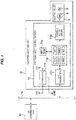
- Fig. 1 is a system block diagram showing an electric valve control device according to a first embodiment of the invention and an electric valve device including the same. Further, in the following description, an exemplary case in which the electric valve control device according to the invention is applied to an expansion valve of a refrigeration cycle system used in a car air conditioner will be described.
- An electric valve device 12 of the embodiment shown in the drawings has a configuration in which an electric valve 9 and an electric valve control device 11 are connected to each other by a lead wire or the like and are integrated with each other while not being separated from each other.
- the electric valve 9 includes an expansion valve 5 which includes a valve body (not shown) controlling a flow rate of a fluid (a refrigerant) and a stepping motor 8 which drives a valve body of the expansion valve 5 and a valve opening degree of the expansion valve 5 (the electric valve 9) is adjusted by the rotation of the stepping motor 8.
- the expansion valve 5 may be a shut valve which opens or closes a refrigerant passage so that the flow of the refrigerant is allowed or interrupted, a three-way valve (a passage switching valve) which switches a refrigerant flow direction, or the like.
- a compressor, a condenser, (the expansion valve 5 of) the electric valve 9, and an evaporator are sequentially connected to one another through a pipe and a flow rate of a refrigerant flowing through the pipe is controlled by the adjustment of the valve opening degree (the expansion valve 5 of) the electric valve 9.
- a battery power (+Vb, GND) of the vehicle is connected to the electric valve control device 11 and, for example, a LIN bus (or a CAN bus) 14 which is an in-vehicle LAN used for a communication inside the vehicle is connected thereto.
- the electric valve control device 11 serves as a slave node, receives an instruction of an initialization operation or the number of pulses of a stepping motor 8 by a LIN communication signal transmitted from an air conditioner ECU 16 of a master node which is a control device of a system connected to the same LIN bus 14 (in the case of a CAN bus, a CAN communication signal), and controls an opening degree (a valve opening degree) of the electric valve 9 (the expansion valve 5).
- an input/output (LIN communication, CAN communication, etc.) to a serial interface an input/output to an I/O port by a digital signal (an ON-OFF signal, etc.), an input/output using a wireless connection (Wi-Fi (Registered Trademark), Bluetooth (Registered Trademark), etc), and the like may be exemplified.
- Wi-Fi Registered Trademark
- Bluetooth Registered Trademark
- any method may be adopted and the invention is not limited to the LIN communication or the CAN communication described above.
- the electric valve control device 11 mainly includes a regulator 11 a which generates a power +Vc (for example, +5 Vdc) used in a circuit inside the electric valve control device 11 from the battery power +Vb (for example, +12 Vdc), a microcomputer 11 b which includes a ROM storing a program controlling the rotation of the stepping motor 8 on the basis of a LIN communication signal transmitted from the air conditioner ECU 16 via the LIN bus 14, a CPU which executes the program stored in the ROM or performs a calculation process, a RAM which temporarily stores data necessary for executing a program of communication data or a situation of an initialization operation, an I/O circuit which performs an input/output with respect to a peripheral circuit, a timer which counts a time of an interrupting process, and an A/D converter converting an analog signal into a digital signal value, a LIN transceiver 11 c which is a communication unit connected to the LIN bus 14 and converting a voltage level of the LIN bus 14 into
- valve opening degree control unit is obtained.
- IC obtained by integrating two or more of the regulator 11a, LIN transceiver 11c, the stepping motor driver 11d, the EEPROM 11e, and the microcomputer 11 b may be used. In that case, a further decrease in device can be realized.
- a detailed configuration of the electric valve control device 11 is not limited to the above-described configuration, and any configuration may be adopted as long as the invention can be carried out (that is, when the control of the valve opening degree of the electric valve 9 and the initialization control can be performed).
- the air conditioner ECU 16 Since there is a need to determine, for example, a 0 pulse as the initial position of the electric valve 9 when the battery power is input to the electric valve control device 11, the air conditioner ECU 16 transmits an instruction of executing an initialization operation (a first initialization operation) of rotating the stepping motor 8 in the valve closing direction, for example, by the maximum number of pulses or more to the electric valve control device 11 by a LIN communication signal via the LIN bus 14.
- the electric valve control device 11 receiving the LIN communication signal performs an initialization process (an initialization operation for the electric valve 9) (initial positioning of 0 pulse) of rotating the stepping motor 8 in the valve closing direction by the number of pulses (for example, 700 pulses or more) obtained by adding the number of pulses enough for a rotor to collide with a stopper (a rotation stopper) to the maximum number of pulses (for example, 500 pulses) which can be controlled by the electric valve 9.
- an initialization process of rotating the stepping motor 8 in the valve opening direction may be performed instead of an initialization process of rotating the stepping motor in the valve closing direction.
- the electric valve control device 11 in order to perform the initialization process, is provided with a transmitting buffer register (for two bits) for writing an initialization state bit (0 to 3) shown in Fig. 2 and a receiving buffer register (for two bits) for writing an initialization signal bit (0 to 3) shown in Fig. 3 . Accordingly, the content received from the air conditioner ECU 16 (the instruction content of the air conditioner ECU 16) is written in the receiving buffer register and the content transmitted from the electric valve control device 11 to the air conditioner ECU 16 (the state of the initialization operation) is written in the transmitting buffer register (which will be described in detail later).
- the microcomputer 11 b receives an instruction of the initialization operation of rotating the stepping motor in the valve closing direction so that the initialization signal bit of the receiving buffer register is 1 (the maximum number of pulses or more) from the air conditioner ECU 16 (step S22: Yes) while the initialization state bit of the transmitting buffer register is 0 (the normal operation) (step S21: Yes), the initialization state bit of the transmitting buffer register is set to 1 (the initialization operation of rotating the stepping motor in the valve closing direction by the maximum number of pulses or more) (step S23) so that the stepping motor 8 is rotated in the valve closing direction by the maximum number of pulses or more (for example, 700 pulses or more) (step S24).
- the initialization state bit of the transmitting buffer register is set to 1 (the initialization operation of rotating the stepping motor in the valve closing direction by the maximum number of pulses or more) (step S23) so that the stepping motor 8 is rotated in the valve closing direction by the maximum number of pulses or more (for example, 700 pulse
- a signal indicating the current initialization operation is output from the electric valve control device 11 to the air conditioner ECU 16, and the air conditioner ECU 16 stops the opening degree control of the electric valve 9 while the air conditioner ECU 16 receives the signal indicating the current initialization operation.
- the microcomputer 11 b checks whether the stepping motor 8 rotates in the valve closing direction at the maximum number of pulses or more (for example, 700 pulses or more) (step S25), and when a state where the stepping motor 8 rotates in the valve closing direction at the maximum number of pulses or more is checked (that is, when the initialization operation ends), the initialization state bit of the transmitting buffer register is set to 3 (the end of the initialization operation) (step S26).
- the electric valve control device 11 transmits an instruction signal of setting the initialization signal bit of the receiving buffer register to 0 (the normal operation) to the microcomputer 11 b.
- step S27: Yes when the microcomputer 11 b receives an operation instruction of setting the initialization signal bit of the receiving buffer register to 0 (the normal operation) from the air conditioner ECU 16 (step S27: Yes), the initialization state bit of the transmitting buffer register is set to 0 (the normal operation) (step S28), the electric valve 9 enters the normal operation state, and the opening degree control of the electric valve 9 is started in accordance with the instruction of the air conditioner ECU 16.
- step S21: No when the initialization state bit of the transmitting buffer register is not 0 (the normal operation) (step S21: No) or the initialization signal (the initialization operation instruction signal) is not received from the air conditioner ECU 16 (step S22: No), the process ends without performing anything.
- the air conditioner ECU 16 which is an external master node can check the initialization operation state of the electric valve 9 (the current initialization operation state, the initialization operation end state, the normal operation state capable of controlling the valve opening degree of the electric valve).
- a signal indicating the end of the initialization operation is output after the end of the initialization operation of the electric valve 9.
- the air conditioner ECU 16 can check the initialization operation state, that is, the end of the initialization operation. Accordingly, since the valve opening degree control of the electric valve 9 can be performed after the electric valve control device 11 returns for the normal operation (for example, immediately after the end of the initialization operation) after the end of the initialization operation, it is possible to prevent a start delay of the control (the opening degree control) of the electric valve 9 by shortening the waiting period of the air conditioner ECU 16.
- the microcomputer 11 b monitors the initialization signal bit of the receiving buffer register during the initialization operation (after the start of the initialization operation in step S24). Then, when the microcomputer receives an operation instruction of setting the initialization signal bit of the receiving buffer register to 3 (the initialization operation interruption instruction) from the air conditioner ECU 16 (step S31: Yes), the initialization operation is interrupted at that time (step S32).
- the initialization state bit of the transmitting buffer register is set to 3 (the end of the initialization operation) (step S33).
- step S34 when the microcomputer 11 b receives an operation instruction of setting the initialization signal bit of the receiving buffer register to 0 (the normal operation) from the air conditioner ECU 16 (step S34: Yes), the initialization state bit of the transmitting buffer register is set to 0 (the normal operation) (step S35), the electric valve 9 enters the normal operation state, and the opening degree control of the electric valve 9 is started in accordance with the instruction of the air conditioner ECU 16.
- the valve opening degree of the electric valve 9 is controlled on the basis of the current number of pulses (corresponding to the current position) of the stepping motor 8 of the electric valve 9 stored in the EEPROM 11e (or the RAM).
- step S31: No when an operation instruction of setting the initialization signal bit of the receiving buffer register to 3 (the initialization operation interruption instruction) is not received from the air conditioner ECU 16 (step S31: No), the processes of step S25 to S28 shown in Fig. 4 are performed.
- the air conditioner ECU 16 can check the initialization operation state, that is, the interruption of the initialization operation. Accordingly, since the opening degree control of the electric valve 9 can be started after the electric valve control device 11 returns for the normal operation (for example, immediately after the interruption of the initialization operation) after the interruption of the initialization operation, it is possible to prevent a start delay of the control (the opening degree control) of the electric valve 9 by shortening the waiting period of the air conditioner ECU 16, for example, even when there is a need to change the opening degree of the electric valve 9 during the initialization operation.
- the valve opening degree of the electric valve 9 is controlled on the basis of the current number of pulses (corresponding to the current position) of the stepping motor 8 of the electric valve 9 stored in the EEPROM 11e (or the RAM). For this reason, it is possible to accurately control the valve opening degree of the electric valve 9 even when the initialization operation is interrupted.
- a signal indicating the end of the initialization operation is output after the interruption of the initialization operation of the electric valve 9, but a signal indicating the interruption of the initialization operation may be output instead of the signal indicating the end of the initialization operation. That is, a bit indicating the interruption of the initialization operation may be provided in the transmitting buffer register separately from the initialization operation end bit and may be used separately from the bit indicating the end of the initialization operation of the first embodiment.
- the initialization state bit of the transmitting buffer register may be set to 3 (the end of the initialization operation) when the initialization operation ends without any interruption and the initialization state bit of the transmitting buffer register may be set to 4 (the interruption of the initialization operation) when the initialization operation is interrupted.
- the electric valve control device 11 knows the current position (the number of pulses) of the stepping motor 8 and performs the initialization process (the initialization operation or the second initialization operation) (the initial positioning of 0 pulse) of rotating the stepping motor 8 in the valve closing direction by the number of pulses obtained by adding the number of pulses enough for the rotor to reliably collide with the stopper at the current position (the number of pulses).
- the electric valve control device 11 knows the current position (the number of pulses) of the stepping motor 8 and performs the initialization process (the initialization operation or the second initialization operation) (the initial positioning of 0 pulse) of rotating the stepping motor 8 in the valve closing direction by the number of pulses obtained by adding the number of pulses enough for the rotor to reliably collide with the stopper at the current position (the number of pulses).
- the microcomputer 11 b receives an instruction of the initialization operation of rotating the stepping motor in the valve closing direction so that the initialization signal bit of the receiving buffer register is 2 (the current number of pulses or more) from the air conditioner ECU 16 (step S42: Yes) while the initialization state bit of the transmitting buffer register is 0 (the normal operation) (step S21: Yes), the initialization state bit of the transmitting buffer register is set to 2 (the initialization operation of rotating the stepping motor in the valve closing direction by the current number of pulses or more) (step S43) so that the stepping motor 8 is rotated in the valve closing direction by the current number of pulses or more (step S44).
- the number of pulses necessary for the initialization operation in this case can be calculated by adding a predetermined number of pulses to the current number of pulses of the stepping motor 8 of the electric valve 9 stored in the EEPROM 11 e (or the RAM) (for example, when the current number of pulses is 100 pulses, 140 pulses are obtained by adding a predetermined number of pulses corresponding to 40 pulses to the current number of pulses) or applying a predetermined coefficient thereto.
- the number of pulses for the initialization operation rotating the stepping motor 8 in the valve closing direction is set to 200 pulses or more (for example, 240 pulses obtained by adding a predetermined number of pulses corresponding to 40 pulses to 200 pulses).
- the number of pulses for the initialization operation of rotating the stepping motor 8 in the valve opening direction is set to the number of pulses (300 pulses) or more obtained by subtracting the current number of pulses (200 pulses) from the maximum number of pulses (500 pulses) (for example, 340 pulses obtained by adding a predetermined number of pulses corresponding to 40 pulses to 300 pulses).
- the air conditioner ECU 16 interrupts the opening degree control of the electric valve 9 while the air conditioner ECU 16 receives a signal indicating the current initialization operation.
- the microcomputer 11 b checks whether the stepping motor 8 rotates by the current number of pulses or more in the valve closing direction every regular time (step S45). Then, when the microcomputer checks that the stepping motor 8 rotates by the current number of pulses or more in the valve closing direction (that is, when the initialization operation ends), the initialization state bit of the transmitting buffer register is set to 3 (the end of the initialization operation) (step S46).
- the electric valve control device 11 transmits an instruction signal of setting the initialization signal bit of the receiving buffer register to 0 (the normal operation) to the microcomputer 11 b.
- step S47 when the microcomputer 11 b receives an instruction operation of setting the initialization signal bit of the receiving buffer register to 0 (the normal operation) from the air conditioner ECU 16 (step S47: Yes), the initialization state bit of the transmitting buffer register is set to 0 (the normal operation) (step S48), the electric valve 9 enters the normal operation state, and the opening degree control of the electric valve 9 is started in accordance with the instruction of the air conditioner ECU 16.
- the electric valve control device 11 of the embodiment since the same operation and effect as those of the first embodiment can be obtained and the initialization operation of the electric valve 9 is performed by using the number of pulses derived from the current number of pulses (corresponding to the current position) of the stepping motor 8 of the electric valve 9 stored in the EEPROM 11e (or the RAM), it is possible to shorten a time necessary for the initialization operation.
- the electric valve control device 11 and the electric valve device 12 are applied to the expansion valve 5 (the electric valve 9) used in the refrigeration cycle system of the car air conditioner, but the invention is not limited to the expansion valve 5.
- the electric valve including a fluid inlet, a fluid outlet, a valve body controlling a flow rate of a fluid flowing out of the outlet, and a motor driving the valve body
- the electric valve control device 11 and the electric valve device 12 according to the invention can be, of course, employed.
- a motored shut valve which allows or interrupts a flow of a refrigerant by opening or closing a refrigerant passage or a passage switching valve such as a three-way valve or a four-way valve switching a refrigerant flow direction may be, of course, employed.
Landscapes
- Engineering & Computer Science (AREA)
- General Engineering & Computer Science (AREA)
- Physics & Mathematics (AREA)
- Mechanical Engineering (AREA)
- Thermal Sciences (AREA)
- General Physics & Mathematics (AREA)
- Automation & Control Theory (AREA)
- Electromagnetism (AREA)
- Radar, Positioning & Navigation (AREA)
- Electrically Driven Valve-Operating Means (AREA)
- Air-Conditioning For Vehicles (AREA)
- Control Of Stepping Motors (AREA)
Abstract
Description
- The present invention relates to an electric valve control device and an electric valve device including the same, and particularly, to an electric valve control device controlling a valve opening degree of an electric valve and an electric valve device including the same.
- Hitherto, in a refrigeration cycle system used for air conditioners, refrigerating/freezing showcases, and the like, there is a need to adjust a flow rate of a circulating refrigerant for the purpose of a highly efficient operation while stabilizing a cooling capacity and keeping a constant superheat degree. Then, in order to highly accurately perform the adjustment at that time, an electric valve which is an electric expansion valve for operating a valve body by a stepping motor corresponding to an expansion valve for a flow rate control has been widely used. Further, there is also known an electric valve such as a three-way valve (a passage switching valve) of switching a refrigerant flow direction or a shut valve of allowing or interrupting a flow of a refrigerant by opening or closing a refrigerant passage using a stepping motor.
- However, in the above-described electric valve using the stepping motor, it is general to control an opening degree by using an open loop control which does not have a feedback of an absolute opening degree (an actual opening degree). Further, the valve body inside the valve stops at a position at the time of the interruption of power while not returning to an initial position when the supply of power is stopped. For that reason, there is a problem in which the valve body stopping position (the absolute opening degree) cannot be accurately recognized when power is input at the next time.
- Regarding the control of the above-described electric valve using the stepping motor, an initialization process (also referred to as original positioning, reference positioning, or initialization) is performed when power is normally input for the positioning of the valve body and the opening degree control is started (for example, see Patent Document 1). Here, the initialization process is a process of sufficiently rotating the stepping motor in a valve closing direction or a valve opening direction by the number of pulses exceeding a full stroke from a full open position to a full close position or vice versa, that is, the number of pulses in which a rotor of the stepping motor collides with a rotation stopper called a stopper so that its rotation is stopped. Accordingly, the initial position of the electric valve at 0 pulse or a maximum pulse is defined.
- Patent Document 1:
JP 4032993 B2 - Incidentally, in the initialization process, for example, the stepping motor is operated in a control pulse range or more (for example, 700 pulses or more). For this reason, in the electric valve of which a control range is 0 to 500 pulses and an excitation speed is 80 pps, for example, a time equal to or longer than 700 ÷ 80 = 8.75 seconds is necessary. In general, this initialization process is performed by stopping the operation of the compressor constituting the refrigeration cycle (for example, see Patent Document 1), and in this period, the system (the refrigeration cycle system) cannot adjust the flow rate of the fluid (the refrigerant) by controlling the opening degree of the electric valve.
- That is, in the related art, the system control device does not take any measure of checking the initialization process state. For this reason, there is a need to wait for a time equal to or longer than a time in which the initialization process (the electric valve initialization operation) is expected to end. As a result, a problem arises in that there is a start delay of the control of the system (that is, the electric valve). Further, even when there is an attempt to perform the electric valve opening degree control during the initialization operation, a problem arises in that the electric valve opening degree control is not performed until the initialization process ends.
- The invention has been made in view of the above-described circumstances and an object of the invention is to provide an electric valve control device capable of preventing a start delay of an electric valve control (an opening degree control) by shortening a waiting period of a system control device and an electric valve device including the same.
- In order to solve the above-described problems, according to the invention, there is provided an electric valve control device controlling a valve opening degree of an electric valve including a valve body and a motor driving the valve body, in which a signal indicating an end or an interruption of an electric valve initialization operation is output after the electric valve initialization operation ends or is interrupted.
- In a desirable aspect, when a transmission request signal is received from the outside after the electric valve initialization operation ends or is interrupted, a signal indicating the end or the interruption of the initialization operation is output.
- In another desirable aspect, a signal indicating the current electric valve initialization operation is output during the electric valve initialization operation.
- In a still another desirable aspect, when the transmission request signal is received during the electric valve initialization operation, a signal indicating the current initialization operation is output.
- In another desirable aspect, following operations are performed sequentially such that the electric valve initialization operation is started when an initialization operation instruction signal is received from the outside, a signal indicating the current initialization operation is output during the initialization operation, an initialization operation end signal is output when the electric valve initialization operation ends, and the electric valve enters a normal operation state when a normal operation instruction signal is received from the outside.
- In another desirable aspect, following operations are performed sequentially such that the electric valve initialization operation is started when an initialization operation instruction signal is received from the outside, a signal indicating the current the initialization operation is output during the initialization operation, the initialization operation is interrupted when an initialization operation interruption instruction signal is received from the outside during the electric valve initialization operation, an initialization operation interruption signal is output, and the electric valve enters a normal operation state when a normal operation instruction signal is received from the outside.
- Desirably, the electric valve initialization operation includes a first initialization operation of allowing a rotation in a valve closing direction or a valve opening direction by a predetermined number of pulses equal to or larger than a maximum number of pulses which can be controlled by the electric valve regardless of the current number of pulses of the electric valve and a second initialization operation of allowing a rotation in the valve closing direction or the valve opening direction by the number of pulses derived on the basis of the current number of pulses of the electric valve.
- In a further desirable aspect, the initialization operation instruction signal received from the outside includes a first initialization operation instruction signal and a second initialization operation instruction signal.
- In a still desirable aspect, an initialization operation end state is written to a transmitting buffer register when the initialization operation ends or is interrupted and the content written in the transmitting buffer register is output to the outside when the transmission request signal is received from the outside.
- In a still desirable aspect, a current initialization operation state is written to a transmitting buffer register during the initialization operation and the content written in the transmitting buffer register is output to the outside when the transmission request signal is received from the outside.
- In another desirable aspect, the electric valve further includes a storage unit storing a current position of the electric valve, in which when the initialization operation is interrupted during the initialization operation, the valve opening degree of the electric valve is controlled on the basis of the current position stored in the storage unit.
- In another desirable aspect, the electric valve further includes a storage unit storing a current position of the electric valve, in which the second initialization operation of allowing the rotation in the valve closing direction by the number of pulses equal to or larger than the current number of pulses of the electric valve or allowing the rotation in the valve opening direction by the number of pulses obtained by subtracting the current number of pulses from the maximum number of pulses on the basis of the number of pulses derived from the current position stored in the storage unit is performed.
- In another desirable aspect, the electric valve control device is connected to the outside by a LIN communication or a CAN communication.
- Further, an electric valve device of the invention is obtained by integrating the electric valve and the electric valve control device.
- According to the invention, since the electric valve control device controlling the valve opening degree of the electric valve outputs a signal indicating the interruption or the end of the initialization operation after the electric valve initialization operation ends or is interrupted, the system control device can check the end or the interruption of the initialization operation. Accordingly, since the electric valve opening degree control can be started after the electric valve control device returns for the normal operation (for example, immediately after the end or the interruption of the initialization operation) after the end or the interruption of the initialization operation, it is possible to prevent a start delay of the electric valve control (the opening degree control) by shortening the waiting period of the system control device.
-
-
Fig. 1 is a system block diagram showing an electric valve control device according to a first embodiment of the invention and an electric valve device including the same; -
Fig. 2 is a diagram showing a transmitting buffer register in a LIN communication of the electric valve control device shown inFig. 1 ; -
Fig. 3 is a diagram showing a receiving buffer register in the LIN communication of the electric valve control device shown inFig. 1 ; -
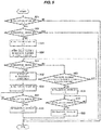
Fig. 4 is a flowchart showing a process flow of an initialization process using the electric valve control device shown inFig. 1 ; -
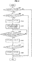
Fig. 5 is a flowchart showing a process flow of an initialization process using an electric valve control device according to a second embodiment of the invention; and -
Fig. 6 is a flowchart showing a process flow of an initialization process using an electric valve control device according to a third embodiment of the invention. - Hereinafter, embodiments of the invention will be described with reference to the drawings.
-
Fig. 1 is a system block diagram showing an electric valve control device according to a first embodiment of the invention and an electric valve device including the same. Further, in the following description, an exemplary case in which the electric valve control device according to the invention is applied to an expansion valve of a refrigeration cycle system used in a car air conditioner will be described. - An
electric valve device 12 of the embodiment shown in the drawings has a configuration in which anelectric valve 9 and an electricvalve control device 11 are connected to each other by a lead wire or the like and are integrated with each other while not being separated from each other. Here, theelectric valve 9 includes anexpansion valve 5 which includes a valve body (not shown) controlling a flow rate of a fluid (a refrigerant) and astepping motor 8 which drives a valve body of theexpansion valve 5 and a valve opening degree of the expansion valve 5 (the electric valve 9) is adjusted by the rotation of thestepping motor 8. In addition, theexpansion valve 5 may be a shut valve which opens or closes a refrigerant passage so that the flow of the refrigerant is allowed or interrupted, a three-way valve (a passage switching valve) which switches a refrigerant flow direction, or the like. - Although not shown in the drawings, for example, in a refrigeration cycle system used in a car air conditioner, a compressor, a condenser, (the
expansion valve 5 of) theelectric valve 9, and an evaporator are sequentially connected to one another through a pipe and a flow rate of a refrigerant flowing through the pipe is controlled by the adjustment of the valve opening degree (theexpansion valve 5 of) theelectric valve 9. - A battery power (+Vb, GND) of the vehicle is connected to the electric
valve control device 11 and, for example, a LIN bus (or a CAN bus) 14 which is an in-vehicle LAN used for a communication inside the vehicle is connected thereto. The electricvalve control device 11 serves as a slave node, receives an instruction of an initialization operation or the number of pulses of a steppingmotor 8 by a LIN communication signal transmitted from anair conditioner ECU 16 of a master node which is a control device of a system connected to the same LIN bus 14 (in the case of a CAN bus, a CAN communication signal), and controls an opening degree (a valve opening degree) of the electric valve 9 (the expansion valve 5). - Additionally, as a communication method between the
air conditioner ECU 16 and the electricvalve control device 11, an input/output (LIN communication, CAN communication, etc.) to a serial interface, an input/output to an I/O port by a digital signal (an ON-OFF signal, etc.), an input/output using a wireless connection (Wi-Fi (Registered Trademark), Bluetooth (Registered Trademark), etc), and the like may be exemplified. Here, any method may be adopted and the invention is not limited to the LIN communication or the CAN communication described above. - The electric
valve control device 11 mainly includes aregulator 11 a which generates a power +Vc (for example, +5 Vdc) used in a circuit inside the electricvalve control device 11 from the battery power +Vb (for example, +12 Vdc), amicrocomputer 11 b which includes a ROM storing a program controlling the rotation of thestepping motor 8 on the basis of a LIN communication signal transmitted from theair conditioner ECU 16 via theLIN bus 14, a CPU which executes the program stored in the ROM or performs a calculation process, a RAM which temporarily stores data necessary for executing a program of communication data or a situation of an initialization operation, an I/O circuit which performs an input/output with respect to a peripheral circuit, a timer which counts a time of an interrupting process, and an A/D converter converting an analog signal into a digital signal value, aLIN transceiver 11 c which is a communication unit connected to theLIN bus 14 and converting a voltage level of theLIN bus 14 into a voltage level of a circuit inside the electricvalve control device 11 so as to enable a LIN communication with themicrocomputer 11b, astepping motor driver 11d which controls the rotation of thestepping motor 8 of theelectric valve 9 on the basis of a driving signal from themicrocomputer 11b, and an EEPROM 11e which is connected to themicrocomputer 11 b and is a nonvolatile memory serving a storage unit storing data to be stored even in the event of the disconnection of the battery power among the RAM data of themicrocomputer 11 b. Here, these components are mounted on a circuit board (not shown). By themicrocomputer 11b and thestepping motor driver 11 d, both the valve opening degree control unit and the initialization control unit are obtained. In addition, an IC obtained by integrating two or more of theregulator 11a,LIN transceiver 11c, thestepping motor driver 11d, the EEPROM 11e, and themicrocomputer 11 b may be used. In that case, a further decrease in device can be realized. - In addition, a detailed configuration of the electric
valve control device 11 is not limited to the above-described configuration, and any configuration may be adopted as long as the invention can be carried out (that is, when the control of the valve opening degree of theelectric valve 9 and the initialization control can be performed). - Since there is a need to determine, for example, a 0 pulse as the initial position of the
electric valve 9 when the battery power is input to the electricvalve control device 11, theair conditioner ECU 16 transmits an instruction of executing an initialization operation (a first initialization operation) of rotating the steppingmotor 8 in the valve closing direction, for example, by the maximum number of pulses or more to the electricvalve control device 11 by a LIN communication signal via theLIN bus 14. - Since the current position (the number of pulses) of the stepping
motor 8 is not given when the battery power is input, the electricvalve control device 11 receiving the LIN communication signal performs an initialization process (an initialization operation for the electric valve 9) (initial positioning of 0 pulse) of rotating the steppingmotor 8 in the valve closing direction by the number of pulses (for example, 700 pulses or more) obtained by adding the number of pulses enough for a rotor to collide with a stopper (a rotation stopper) to the maximum number of pulses (for example, 500 pulses) which can be controlled by theelectric valve 9. In addition, an initialization process of rotating the steppingmotor 8 in the valve opening direction may be performed instead of an initialization process of rotating the stepping motor in the valve closing direction. - In addition, in this example, in order to perform the initialization process, the electric
valve control device 11 is provided with a transmitting buffer register (for two bits) for writing an initialization state bit (0 to 3) shown inFig. 2 and a receiving buffer register (for two bits) for writing an initialization signal bit (0 to 3) shown inFig. 3 . Accordingly, the content received from the air conditioner ECU 16 (the instruction content of the air conditioner ECU 16) is written in the receiving buffer register and the content transmitted from the electricvalve control device 11 to the air conditioner ECU 16 (the state of the initialization operation) is written in the transmitting buffer register (which will be described in detail later). - Next, a process flow of an initialization process using (the
microcomputer 11 b of) the electricvalve control device 11 will be described with reference toFig. 4 . This process is performed, for example, every regular time. - First, when the
microcomputer 11 b receives an instruction of the initialization operation of rotating the stepping motor in the valve closing direction so that the initialization signal bit of the receiving buffer register is 1 (the maximum number of pulses or more) from the air conditioner ECU 16 (step S22: Yes) while the initialization state bit of the transmitting buffer register is 0 (the normal operation) (step S21: Yes), the initialization state bit of the transmitting buffer register is set to 1 (the initialization operation of rotating the stepping motor in the valve closing direction by the maximum number of pulses or more) (step S23) so that the steppingmotor 8 is rotated in the valve closing direction by the maximum number of pulses or more (for example, 700 pulses or more) (step S24). - A signal indicating the current initialization operation is output from the electric
valve control device 11 to theair conditioner ECU 16, and theair conditioner ECU 16 stops the opening degree control of theelectric valve 9 while theair conditioner ECU 16 receives the signal indicating the current initialization operation. - The
microcomputer 11 b checks whether the steppingmotor 8 rotates in the valve closing direction at the maximum number of pulses or more (for example, 700 pulses or more) (step S25), and when a state where the steppingmotor 8 rotates in the valve closing direction at the maximum number of pulses or more is checked (that is, when the initialization operation ends), the initialization state bit of the transmitting buffer register is set to 3 (the end of the initialization operation) (step S26). - When the
air conditioner ECU 16 receives the initialization operation end signal output from the electricvalve control device 11, the electricvalve control device 11 transmits an instruction signal of setting the initialization signal bit of the receiving buffer register to 0 (the normal operation) to themicrocomputer 11 b. - Next, when the
microcomputer 11 b receives an operation instruction of setting the initialization signal bit of the receiving buffer register to 0 (the normal operation) from the air conditioner ECU 16 (step S27: Yes), the initialization state bit of the transmitting buffer register is set to 0 (the normal operation) (step S28), theelectric valve 9 enters the normal operation state, and the opening degree control of theelectric valve 9 is started in accordance with the instruction of theair conditioner ECU 16. - In addition, when the initialization state bit of the transmitting buffer register is not 0 (the normal operation) (step S21: No) or the initialization signal (the initialization operation instruction signal) is not received from the air conditioner ECU 16 (step S22: No), the process ends without performing anything.
- When the
microcomputer 11 b receives the transmission request signal from theair conditioner ECU 16 via theLIN bus 14 according to the LIN communication, the content of the transmitting buffer register at that time is transmitted to theair conditioner ECU 16 as the LIN communication signal via theLIN transceiver 11 c corresponding to a communication unit and theLIN bus 14. Accordingly, theair conditioner ECU 16 which is an external master node can check the initialization operation state of the electric valve 9 (the current initialization operation state, the initialization operation end state, the normal operation state capable of controlling the valve opening degree of the electric valve). - In this way, in the electric
valve control device 11 of the embodiment, a signal indicating the end of the initialization operation is output after the end of the initialization operation of theelectric valve 9. For this reason, theair conditioner ECU 16 can check the initialization operation state, that is, the end of the initialization operation. Accordingly, since the valve opening degree control of theelectric valve 9 can be performed after the electricvalve control device 11 returns for the normal operation (for example, immediately after the end of the initialization operation) after the end of the initialization operation, it is possible to prevent a start delay of the control (the opening degree control) of theelectric valve 9 by shortening the waiting period of theair conditioner ECU 16. - Next, a process flow of an initialization process using (the
microcomputer 11 b of) the electric valve control device according to a second embodiment of the invention will be described with reference toFig. 5 . The configurations of the electric valve control device of the second embodiment and the electric valve device including the same are the same as those of the electricvalve control device 11 of the first embodiment and theelectric valve device 12 including the same, but a difference from the first embodiment is that the initialization operation is interrupted during the initialization operation. Thus, only the difference will be described below. Then, the same reference numerals will be given to the same components as those of the first embodiment and the detailed description will be omitted. - That is, the
microcomputer 11 b monitors the initialization signal bit of the receiving buffer register during the initialization operation (after the start of the initialization operation in step S24). Then, when the microcomputer receives an operation instruction of setting the initialization signal bit of the receiving buffer register to 3 (the initialization operation interruption instruction) from the air conditioner ECU 16 (step S31: Yes), the initialization operation is interrupted at that time (step S32). - When the
microcomputer 11 b ends the initialization operation interruption process, the initialization state bit of the transmitting buffer register is set to 3 (the end of the initialization operation) (step S33). - When the
air conditioner ECU 16 receives the initialization operation end signal output from the electricvalve control device 11, an instruction signal of setting the initialization signal bit of the receiving buffer register to 0 (the normal operation) is transmitted to themicrocomputer 11 b. - Next, when the
microcomputer 11 b receives an operation instruction of setting the initialization signal bit of the receiving buffer register to 0 (the normal operation) from the air conditioner ECU 16 (step S34: Yes), the initialization state bit of the transmitting buffer register is set to 0 (the normal operation) (step S35), theelectric valve 9 enters the normal operation state, and the opening degree control of theelectric valve 9 is started in accordance with the instruction of theair conditioner ECU 16. - Here, when the
microcomputer 11 b interrupts the initialization operation during the initialization operation as described above, the valve opening degree of theelectric valve 9 is controlled on the basis of the current number of pulses (corresponding to the current position) of the steppingmotor 8 of theelectric valve 9 stored in theEEPROM 11e (or the RAM). - In addition, when an operation instruction of setting the initialization signal bit of the receiving buffer register to 3 (the initialization operation interruption instruction) is not received from the air conditioner ECU 16 (step S31: No), the processes of step S25 to S28 shown in
Fig. 4 are performed. - In this way, in the electric
valve control device 11 of the embodiment, since a signal indicating the end of the initialization operation is output after the interruption of the initialization operation of theelectric valve 9, theair conditioner ECU 16 can check the initialization operation state, that is, the interruption of the initialization operation. Accordingly, since the opening degree control of theelectric valve 9 can be started after the electricvalve control device 11 returns for the normal operation (for example, immediately after the interruption of the initialization operation) after the interruption of the initialization operation, it is possible to prevent a start delay of the control (the opening degree control) of theelectric valve 9 by shortening the waiting period of theair conditioner ECU 16, for example, even when there is a need to change the opening degree of theelectric valve 9 during the initialization operation. - Further, when the initialization operation is interrupted during the initialization operation, the valve opening degree of the
electric valve 9 is controlled on the basis of the current number of pulses (corresponding to the current position) of the steppingmotor 8 of theelectric valve 9 stored in theEEPROM 11e (or the RAM). For this reason, it is possible to accurately control the valve opening degree of theelectric valve 9 even when the initialization operation is interrupted. - In addition, in the electric
valve control device 11 of the embodiment, a signal indicating the end of the initialization operation is output after the interruption of the initialization operation of theelectric valve 9, but a signal indicating the interruption of the initialization operation may be output instead of the signal indicating the end of the initialization operation. That is, a bit indicating the interruption of the initialization operation may be provided in the transmitting buffer register separately from the initialization operation end bit and may be used separately from the bit indicating the end of the initialization operation of the first embodiment. For example, when the initialization state bit indicating the end of the initialization operation is set to 3 (the end of the initialization operation) and the initialization state bit indicating the interruption of the initialization operation is set to 4 (the interruption of the initialization operation), the initialization state bit of the transmitting buffer register may be set to 3 (the end of the initialization operation) when the initialization operation ends without any interruption and the initialization state bit of the transmitting buffer register may be set to 4 (the interruption of the initialization operation) when the initialization operation is interrupted. - Next, a process flow of an initialization process using (the
microcomputer 11 b of) the electric valve control device according to a third embodiment of the invention will be described with reference toFig. 6 . The configurations of the electric valve control device of the third embodiment and the electric valve device including the same are the same as those of the electricvalve control device 11 of the first embodiment and theelectric valve device 12 including the same, but a difference from the first embodiment is that the electricvalve control device 11 knows the current position (the number of pulses) of the steppingmotor 8 and performs the initialization process (the initialization operation or the second initialization operation) (the initial positioning of 0 pulse) of rotating the steppingmotor 8 in the valve closing direction by the number of pulses obtained by adding the number of pulses enough for the rotor to reliably collide with the stopper at the current position (the number of pulses). Thus, only the difference will be described below. Then, the same reference numerals will be given to the same components as those of the first embodiment and the detailed description will be omitted. - First, when the
microcomputer 11 b receives an instruction of the initialization operation of rotating the stepping motor in the valve closing direction so that the initialization signal bit of the receiving buffer register is 2 (the current number of pulses or more) from the air conditioner ECU 16 (step S42: Yes) while the initialization state bit of the transmitting buffer register is 0 (the normal operation) (step S21: Yes), the initialization state bit of the transmitting buffer register is set to 2 (the initialization operation of rotating the stepping motor in the valve closing direction by the current number of pulses or more) (step S43) so that the steppingmotor 8 is rotated in the valve closing direction by the current number of pulses or more (step S44). - In addition, the number of pulses necessary for the initialization operation in this case (the number of pulses for the initialization operation) can be calculated by adding a predetermined number of pulses to the current number of pulses of the stepping
motor 8 of theelectric valve 9 stored in theEEPROM 11 e (or the RAM) (for example, when the current number of pulses is 100 pulses, 140 pulses are obtained by adding a predetermined number of pulses corresponding to 40 pulses to the current number of pulses) or applying a predetermined coefficient thereto. - Here, a method of deriving the number of pulses for the initialization operation of the embodiment will be described by exemplifying another example. In the
electric valve 9 of which the maximum number of pulses is 500 pulses, when the current number of pulses of the steppingmotor 8 of theelectric valve 9 stored in theEEPROM 11e (or the RAM) is 200 pulses, the number of pulses for the initialization operation rotating the steppingmotor 8 in the valve closing direction is set to 200 pulses or more (for example, 240 pulses obtained by adding a predetermined number of pulses corresponding to 40 pulses to 200 pulses). Further, the number of pulses for the initialization operation of rotating the steppingmotor 8 in the valve opening direction is set to the number of pulses (300 pulses) or more obtained by subtracting the current number of pulses (200 pulses) from the maximum number of pulses (500 pulses) (for example, 340 pulses obtained by adding a predetermined number of pulses corresponding to 40 pulses to 300 pulses). - When a signal indicating the current initialization operation is output from the electric
valve control device 11 to theair conditioner ECU 16, theair conditioner ECU 16 interrupts the opening degree control of theelectric valve 9 while theair conditioner ECU 16 receives a signal indicating the current initialization operation. - The
microcomputer 11 b checks whether the steppingmotor 8 rotates by the current number of pulses or more in the valve closing direction every regular time (step S45). Then, when the microcomputer checks that the steppingmotor 8 rotates by the current number of pulses or more in the valve closing direction (that is, when the initialization operation ends), the initialization state bit of the transmitting buffer register is set to 3 (the end of the initialization operation) (step S46). - When the
air conditioner ECU 16 receives the initialization operation end signal output from the electricvalve control device 11, the electricvalve control device 11 transmits an instruction signal of setting the initialization signal bit of the receiving buffer register to 0 (the normal operation) to themicrocomputer 11 b. - Next, when the
microcomputer 11 b receives an instruction operation of setting the initialization signal bit of the receiving buffer register to 0 (the normal operation) from the air conditioner ECU 16 (step S47: Yes), the initialization state bit of the transmitting buffer register is set to 0 (the normal operation) (step S48), theelectric valve 9 enters the normal operation state, and the opening degree control of theelectric valve 9 is started in accordance with the instruction of theair conditioner ECU 16. - In this way, in the electric
valve control device 11 of the embodiment, since the same operation and effect as those of the first embodiment can be obtained and the initialization operation of theelectric valve 9 is performed by using the number of pulses derived from the current number of pulses (corresponding to the current position) of the steppingmotor 8 of theelectric valve 9 stored in theEEPROM 11e (or the RAM), it is possible to shorten a time necessary for the initialization operation. - In addition, in the first to third embodiments, a case has been exemplified in which the electric
valve control device 11 and theelectric valve device 12 are applied to the expansion valve 5 (the electric valve 9) used in the refrigeration cycle system of the car air conditioner, but the invention is not limited to theexpansion valve 5. In the case of the electric valve including a fluid inlet, a fluid outlet, a valve body controlling a flow rate of a fluid flowing out of the outlet, and a motor driving the valve body, the electricvalve control device 11 and theelectric valve device 12 according to the invention can be, of course, employed. Further, for example, a motored shut valve which allows or interrupts a flow of a refrigerant by opening or closing a refrigerant passage or a passage switching valve such as a three-way valve or a four-way valve switching a refrigerant flow direction may be, of course, employed. -
- 5
- expansion valve
- 8
- stepping motor
- 9
- electric valve
- 11
- electric valve control device
- 11 a
- regulator
- 11 b
- microcomputer
- 11c
- LIN transceiver
- 11 d
- stepping motor driver
- 11 e
- EEPROM (storage unit)
- 12
- electric valve device
- 14
- LIN bus
- 16
- air conditioner ECU
Claims (14)
- An electric valve control device controlling a valve opening degree of an electric valve including a valve body and a motor driving the valve body,
wherein a signal indicating an end or an interruption of an electric valve initialization operation is output after the electric valve initialization operation ends or is interrupted. - The electric valve control device according to claim 1,
wherein when a transmission request signal is received from the outside after the electric valve initialization operation ends or is interrupted, a signal indicating the end or the interruption of the initialization operation is output. - The electric valve control device according to claim 1 or 2,
wherein a signal indicating the current electric valve initialization operation is output during the electric valve initialization operation. - The electric valve control device according to claim 3,
wherein when the transmission request signal is received from the outside during the electric valve initialization operation, a signal indicating the current initialization operation is output. - The electric valve control device according to any one of claims 1 to 4,
wherein following operations are performed sequentially such that the electric valve initialization operation is started when an initialization operation instruction signal is received from the outside, a signal indicating the current initialization operation is output during the initialization operation, an initialization operation end signal is output when the electric valve initialization operation ends, and the electric valve enters a normal operation state when a normal operation instruction signal is received from the outside. - The electric valve control device according to any one of claims 1 to 4,
wherein following operations are performed sequentially such that the electric valve initialization operation is started when an initialization operation instruction signal is received from the outside, a signal indicating the current the initialization operation is output during the initialization operation, the initialization operation is interrupted when an initialization operation interruption instruction signal is received from the outside during the electric valve initialization operation, an initialization operation interruption signal is output, and the electric valve enters a normal operation state when a normal operation instruction signal is received from the outside. - The electric valve control device according to any one of claims 1 to 6,
wherein the electric valve initialization operation includes a first initialization operation of allowing a rotation in a valve closing direction or a valve opening direction by a predetermined number of pulses equal to or larger than a maximum number of pulses which can be controlled by the electric valve regardless of the current number of pulses of the electric valve and a second initialization operation of allowing a rotation in the valve closing direction or the valve opening direction by the number of pulses derived on the basis of the current number of pulses of the electric valve. - The electric valve control device according to claim 7,
wherein the initialization operation instruction signal received from the outside includes a first initialization operation instruction signal and a second initialization operation instruction signal. - The electric valve control device according to claim 2,
wherein an initialization operation end state is written to a transmitting buffer register when the initialization operation ends or is interrupted and the content written in the transmitting buffer register is output to the outside when the transmission request signal is received from the outside. - The electric valve control device according to claim 4,
wherein a current initialization operation state is written to a transmitting buffer register during the initialization operation and the content written in the transmitting buffer register is output to the outside when the transmission request signal is received from the outside. - The electric valve control device according to any one of claims 1 to 10, further comprising:a storage unit storing a current position of the electric valve,wherein when the initialization operation is interrupted during the initialization operation, the valve opening degree of the electric valve is controlled on the basis of the current position stored in the storage unit.
- The electric valve control device according to any one of claims 1 to 10, further comprising:a storage unit storing a current position of the electric valve,wherein the second initialization operation of allowing the rotation in the valve closing direction by the number of pulses equal to or larger than the current number of pulses of the electric valve or allowing the rotation in the valve opening direction by the number of pulses obtained by subtracting the current number of pulses from the maximum number of pulses on the basis of the number of pulses derived from the current position stored in the storage unit is performed.
- The electric valve control device according to any one of claims 1 to 12,
wherein the electric valve control device is connected to the outside by a LIN communication or a CAN communication. - An electric valve device obtained by integrating the electric valve and the electric valve control device according to any one of claims 1 to 13.
Applications Claiming Priority (1)
| Application Number | Priority Date | Filing Date | Title |
|---|---|---|---|
| JP2016186486A JP6600608B2 (en) | 2016-09-26 | 2016-09-26 | Electric valve control device and electric valve device provided with the same |
Publications (2)
| Publication Number | Publication Date |
|---|---|
| EP3299748A1 true EP3299748A1 (en) | 2018-03-28 |
| EP3299748B1 EP3299748B1 (en) | 2020-09-30 |
Family
ID=60021882
Family Applications (1)
| Application Number | Title | Priority Date | Filing Date |
|---|---|---|---|
| EP17192271.9A Active EP3299748B1 (en) | 2016-09-26 | 2017-09-21 | Electric valve control device and electric valve device including the same |
Country Status (4)
| Country | Link |
|---|---|
| US (1) | US10774942B2 (en) |
| EP (1) | EP3299748B1 (en) |
| JP (1) | JP6600608B2 (en) |
| CN (1) | CN107883045B (en) |
Families Citing this family (4)
| Publication number | Priority date | Publication date | Assignee | Title |
|---|---|---|---|---|
| JP6764316B2 (en) * | 2016-10-31 | 2020-09-30 | 株式会社不二工機 | Solenoid valve control device and motorized valve device equipped with it |
| WO2019130928A1 (en) * | 2017-12-26 | 2019-07-04 | 株式会社不二工機 | Electrically operated valve control device, and electrically operated valve device provided with same |
| JP2020133927A (en) | 2019-02-13 | 2020-08-31 | サンデン・オートモーティブクライメイトシステム株式会社 | Vehicle air conditioner |
| CN119099284B (en) * | 2024-09-29 | 2025-12-02 | 中国重汽集团济南动力有限公司 | A vehicle thermal management integrated control method and device |
Citations (4)
| Publication number | Priority date | Publication date | Assignee | Title |
|---|---|---|---|---|
| JP4032993B2 (en) | 2003-02-21 | 2008-01-16 | 松下電器産業株式会社 | Air conditioner |
| US20150362236A1 (en) * | 2013-02-04 | 2015-12-17 | Hangzhou Sanhua Research Institute Co., Ltd. | Electronic expansion valve and control method thereof |
| EP3051218A1 (en) * | 2013-09-28 | 2016-08-03 | Hangzhou Sanhua Research Institute Co., Ltd. | Air conditioning system and method for controlling same |
| US20160221416A1 (en) * | 2013-09-28 | 2016-08-04 | Hangzhou Sanhua Research Institute Co., Ltd | Refrigerant Circulation System |
Family Cites Families (16)
| Publication number | Priority date | Publication date | Assignee | Title |
|---|---|---|---|---|
| JPS63135677A (en) * | 1986-11-28 | 1988-06-08 | Nippon Sangyo Denshi Kk | Valve control device |
| JP2001263830A (en) * | 2000-03-22 | 2001-09-26 | Mitsubishi Electric Corp | Blocking unit and refrigeration cycle device using blocking unit |
| JP4151236B2 (en) * | 2001-06-07 | 2008-09-17 | 三菱電機株式会社 | Flow control device and air conditioner |
| JP3753314B2 (en) * | 2002-02-14 | 2006-03-08 | 三菱電機株式会社 | Control device for motor for controlling internal combustion engine |
| JP4028291B2 (en) * | 2002-05-16 | 2007-12-26 | 株式会社鷺宮製作所 | Motorized valve drive device and refrigeration cycle device |
| JP4379053B2 (en) * | 2002-12-16 | 2009-12-09 | 株式会社デンソー | Electric actuator system |
| JP2005201280A (en) * | 2005-02-02 | 2005-07-28 | Mitsubishi Electric Corp | Flow valve control apparatus and flow valve manufacturing method |
| JP2010179697A (en) * | 2009-02-03 | 2010-08-19 | Sanden Corp | On-vehicle equipment control system |
| JP5404487B2 (en) * | 2010-03-23 | 2014-01-29 | 三菱電機株式会社 | Multi-room air conditioner |
| JP5542884B2 (en) * | 2012-08-30 | 2014-07-09 | 三菱電機株式会社 | In-vehicle engine controller |
| CN103968132B (en) * | 2013-02-04 | 2018-11-02 | 浙江三花汽车零部件有限公司 | A kind of control method and control device of electric expansion valve |
| CN104515252A (en) * | 2013-09-28 | 2015-04-15 | 杭州三花研究院有限公司 | Control method of electronic expansion valve |
| CN103743063B (en) * | 2014-01-17 | 2016-06-22 | 苏州海特温控技术有限公司 | The control method of electric expansion valve during a kind of air conditioner refrigerating |
| JP6492812B2 (en) * | 2015-03-13 | 2019-04-03 | 株式会社デンソー | Actuator control system |
| CN105222445B (en) * | 2015-10-30 | 2017-11-17 | Tcl空调器(中山)有限公司 | Control method and device of electronic expansion valve, air conditioning unit and control method thereof |
| CN105352239B (en) * | 2015-11-02 | 2018-07-31 | 青岛海尔空调器有限总公司 | The control method of air conditioner electronic expansion valve |
-
2016
- 2016-09-26 JP JP2016186486A patent/JP6600608B2/en active Active
-
2017
- 2017-09-11 CN CN201710812445.3A patent/CN107883045B/en active Active
- 2017-09-21 EP EP17192271.9A patent/EP3299748B1/en active Active
- 2017-09-21 US US15/710,906 patent/US10774942B2/en active Active
Patent Citations (4)
| Publication number | Priority date | Publication date | Assignee | Title |
|---|---|---|---|---|
| JP4032993B2 (en) | 2003-02-21 | 2008-01-16 | 松下電器産業株式会社 | Air conditioner |
| US20150362236A1 (en) * | 2013-02-04 | 2015-12-17 | Hangzhou Sanhua Research Institute Co., Ltd. | Electronic expansion valve and control method thereof |
| EP3051218A1 (en) * | 2013-09-28 | 2016-08-03 | Hangzhou Sanhua Research Institute Co., Ltd. | Air conditioning system and method for controlling same |
| US20160221416A1 (en) * | 2013-09-28 | 2016-08-04 | Hangzhou Sanhua Research Institute Co., Ltd | Refrigerant Circulation System |
Also Published As
| Publication number | Publication date |
|---|---|
| JP6600608B2 (en) | 2019-10-30 |
| EP3299748B1 (en) | 2020-09-30 |
| JP2018053908A (en) | 2018-04-05 |
| CN107883045B (en) | 2021-04-09 |
| CN107883045A (en) | 2018-04-06 |
| US20180087687A1 (en) | 2018-03-29 |
| US10774942B2 (en) | 2020-09-15 |
Similar Documents
| Publication | Publication Date | Title |
|---|---|---|
| JP6667925B2 (en) | Electric valve control device and electric valve device provided with the same | |
| EP2679935B1 (en) | Control device for controlling an electrically operated valve | |
| US10571875B2 (en) | Electric valve control device and electric valve device including the same | |
| US10774942B2 (en) | Electric valve control device and electric valve device including the same | |
| JP7503866B2 (en) | Motor-operated valve control device and motor-operated valve device equipped with the same | |
| EP3051234B1 (en) | Refrigerant circulation system | |
| WO2015043416A1 (en) | Air conditioning system and method for controlling same | |
| JP6664730B2 (en) | Electric valve control device and electric valve device provided with the same | |
| US20210019139A1 (en) | Blocking and unblocking mechanism for software updates for a controller | |
| JP6757088B2 (en) | Solenoid valve control device and motorized valve device equipped with it | |
| EP3954951B1 (en) | Air-conditioning device | |
| JP2008089266A (en) | Air conditioner controller | |
| HK1222706B (en) | Refrigerant circulation system |
Legal Events
| Date | Code | Title | Description |
|---|---|---|---|
| PUAI | Public reference made under article 153(3) epc to a published international application that has entered the european phase |
Free format text: ORIGINAL CODE: 0009012 |
|
| STAA | Information on the status of an ep patent application or granted ep patent |
Free format text: STATUS: THE APPLICATION HAS BEEN PUBLISHED |
|
| AK | Designated contracting states |
Kind code of ref document: A1 Designated state(s): AL AT BE BG CH CY CZ DE DK EE ES FI FR GB GR HR HU IE IS IT LI LT LU LV MC MK MT NL NO PL PT RO RS SE SI SK SM TR |
|
| AX | Request for extension of the european patent |
Extension state: BA ME |
|
| STAA | Information on the status of an ep patent application or granted ep patent |
Free format text: STATUS: REQUEST FOR EXAMINATION WAS MADE |
|
| 17P | Request for examination filed |
Effective date: 20180926 |
|
| RBV | Designated contracting states (corrected) |
Designated state(s): AL AT BE BG CH CY CZ DE DK EE ES FI FR GB GR HR HU IE IS IT LI LT LU LV MC MK MT NL NO PL PT RO RS SE SI SK SM TR |
|
| STAA | Information on the status of an ep patent application or granted ep patent |
Free format text: STATUS: EXAMINATION IS IN PROGRESS |
|
| 17Q | First examination report despatched |
Effective date: 20181121 |
|
| REG | Reference to a national code |
Ref country code: DE Ref legal event code: R079 Ref document number: 602017024499 Country of ref document: DE Free format text: PREVIOUS MAIN CLASS: F25B0041060000 Ipc: G05F0001460000 |
|
| GRAP | Despatch of communication of intention to grant a patent |
Free format text: ORIGINAL CODE: EPIDOSNIGR1 |
|
| STAA | Information on the status of an ep patent application or granted ep patent |
Free format text: STATUS: GRANT OF PATENT IS INTENDED |
|
| RIC1 | Information provided on ipc code assigned before grant |
Ipc: G05D 23/19 20060101ALI20200428BHEP Ipc: F25B 49/02 20060101ALI20200428BHEP Ipc: F25B 41/06 20060101ALI20200428BHEP Ipc: G05F 1/46 20060101AFI20200428BHEP |
|
| RAP1 | Party data changed (applicant data changed or rights of an application transferred) |
Owner name: FUJIKOKI CORPORATION |
|
| RIN1 | Information on inventor provided before grant (corrected) |
Inventor name: SATOU, KIYOHARU Inventor name: OGAWA, YOSHIO Inventor name: HAYASHI, AKIHIRO |
|
| INTG | Intention to grant announced |
Effective date: 20200518 |
|
| GRAS | Grant fee paid |
Free format text: ORIGINAL CODE: EPIDOSNIGR3 |
|
| GRAA | (expected) grant |
Free format text: ORIGINAL CODE: 0009210 |
|
| STAA | Information on the status of an ep patent application or granted ep patent |
Free format text: STATUS: THE PATENT HAS BEEN GRANTED |
|
| AK | Designated contracting states |
Kind code of ref document: B1 Designated state(s): AL AT BE BG CH CY CZ DE DK EE ES FI FR GB GR HR HU IE IS IT LI LT LU LV MC MK MT NL NO PL PT RO RS SE SI SK SM TR |
|
| REG | Reference to a national code |
Ref country code: CH Ref legal event code: EP Ref country code: GB Ref legal event code: FG4D |
|
| REG | Reference to a national code |
Ref country code: AT Ref legal event code: REF Ref document number: 1319466 Country of ref document: AT Kind code of ref document: T Effective date: 20201015 |
|
| REG | Reference to a national code |
Ref country code: DE Ref legal event code: R096 Ref document number: 602017024499 Country of ref document: DE |
|
| REG | Reference to a national code |
Ref country code: IE Ref legal event code: FG4D |
|
| PG25 | Lapsed in a contracting state [announced via postgrant information from national office to epo] |
Ref country code: FI Free format text: LAPSE BECAUSE OF FAILURE TO SUBMIT A TRANSLATION OF THE DESCRIPTION OR TO PAY THE FEE WITHIN THE PRESCRIBED TIME-LIMIT Effective date: 20200930 Ref country code: NO Free format text: LAPSE BECAUSE OF FAILURE TO SUBMIT A TRANSLATION OF THE DESCRIPTION OR TO PAY THE FEE WITHIN THE PRESCRIBED TIME-LIMIT Effective date: 20201230 Ref country code: GR Free format text: LAPSE BECAUSE OF FAILURE TO SUBMIT A TRANSLATION OF THE DESCRIPTION OR TO PAY THE FEE WITHIN THE PRESCRIBED TIME-LIMIT Effective date: 20201231 Ref country code: HR Free format text: LAPSE BECAUSE OF FAILURE TO SUBMIT A TRANSLATION OF THE DESCRIPTION OR TO PAY THE FEE WITHIN THE PRESCRIBED TIME-LIMIT Effective date: 20200930 Ref country code: SE Free format text: LAPSE BECAUSE OF FAILURE TO SUBMIT A TRANSLATION OF THE DESCRIPTION OR TO PAY THE FEE WITHIN THE PRESCRIBED TIME-LIMIT Effective date: 20200930 Ref country code: BG Free format text: LAPSE BECAUSE OF FAILURE TO SUBMIT A TRANSLATION OF THE DESCRIPTION OR TO PAY THE FEE WITHIN THE PRESCRIBED TIME-LIMIT Effective date: 20201230 |
|
| REG | Reference to a national code |
Ref country code: AT Ref legal event code: MK05 Ref document number: 1319466 Country of ref document: AT Kind code of ref document: T Effective date: 20200930 |
|
| PG25 | Lapsed in a contracting state [announced via postgrant information from national office to epo] |
Ref country code: LV Free format text: LAPSE BECAUSE OF FAILURE TO SUBMIT A TRANSLATION OF THE DESCRIPTION OR TO PAY THE FEE WITHIN THE PRESCRIBED TIME-LIMIT Effective date: 20200930 Ref country code: RS Free format text: LAPSE BECAUSE OF FAILURE TO SUBMIT A TRANSLATION OF THE DESCRIPTION OR TO PAY THE FEE WITHIN THE PRESCRIBED TIME-LIMIT Effective date: 20200930 |
|
| REG | Reference to a national code |
Ref country code: NL Ref legal event code: MP Effective date: 20200930 |
|
| REG | Reference to a national code |
Ref country code: LT Ref legal event code: MG4D |
|
| PG25 | Lapsed in a contracting state [announced via postgrant information from national office to epo] |
Ref country code: RO Free format text: LAPSE BECAUSE OF FAILURE TO SUBMIT A TRANSLATION OF THE DESCRIPTION OR TO PAY THE FEE WITHIN THE PRESCRIBED TIME-LIMIT Effective date: 20200930 Ref country code: PT Free format text: LAPSE BECAUSE OF FAILURE TO SUBMIT A TRANSLATION OF THE DESCRIPTION OR TO PAY THE FEE WITHIN THE PRESCRIBED TIME-LIMIT Effective date: 20210201 Ref country code: CZ Free format text: LAPSE BECAUSE OF FAILURE TO SUBMIT A TRANSLATION OF THE DESCRIPTION OR TO PAY THE FEE WITHIN THE PRESCRIBED TIME-LIMIT Effective date: 20200930 Ref country code: LT Free format text: LAPSE BECAUSE OF FAILURE TO SUBMIT A TRANSLATION OF THE DESCRIPTION OR TO PAY THE FEE WITHIN THE PRESCRIBED TIME-LIMIT Effective date: 20200930 Ref country code: NL Free format text: LAPSE BECAUSE OF FAILURE TO SUBMIT A TRANSLATION OF THE DESCRIPTION OR TO PAY THE FEE WITHIN THE PRESCRIBED TIME-LIMIT Effective date: 20200930 Ref country code: EE Free format text: LAPSE BECAUSE OF FAILURE TO SUBMIT A TRANSLATION OF THE DESCRIPTION OR TO PAY THE FEE WITHIN THE PRESCRIBED TIME-LIMIT Effective date: 20200930 Ref country code: SM Free format text: LAPSE BECAUSE OF FAILURE TO SUBMIT A TRANSLATION OF THE DESCRIPTION OR TO PAY THE FEE WITHIN THE PRESCRIBED TIME-LIMIT Effective date: 20200930 |
|
| PG25 | Lapsed in a contracting state [announced via postgrant information from national office to epo] |
Ref country code: ES Free format text: LAPSE BECAUSE OF FAILURE TO SUBMIT A TRANSLATION OF THE DESCRIPTION OR TO PAY THE FEE WITHIN THE PRESCRIBED TIME-LIMIT Effective date: 20200930 Ref country code: AL Free format text: LAPSE BECAUSE OF FAILURE TO SUBMIT A TRANSLATION OF THE DESCRIPTION OR TO PAY THE FEE WITHIN THE PRESCRIBED TIME-LIMIT Effective date: 20200930 Ref country code: AT Free format text: LAPSE BECAUSE OF FAILURE TO SUBMIT A TRANSLATION OF THE DESCRIPTION OR TO PAY THE FEE WITHIN THE PRESCRIBED TIME-LIMIT Effective date: 20200930 Ref country code: PL Free format text: LAPSE BECAUSE OF FAILURE TO SUBMIT A TRANSLATION OF THE DESCRIPTION OR TO PAY THE FEE WITHIN THE PRESCRIBED TIME-LIMIT Effective date: 20200930 Ref country code: IS Free format text: LAPSE BECAUSE OF FAILURE TO SUBMIT A TRANSLATION OF THE DESCRIPTION OR TO PAY THE FEE WITHIN THE PRESCRIBED TIME-LIMIT Effective date: 20210130 |
|
| PG25 | Lapsed in a contracting state [announced via postgrant information from national office to epo] |
Ref country code: SK Free format text: LAPSE BECAUSE OF FAILURE TO SUBMIT A TRANSLATION OF THE DESCRIPTION OR TO PAY THE FEE WITHIN THE PRESCRIBED TIME-LIMIT Effective date: 20200930 |
|
| REG | Reference to a national code |
Ref country code: DE Ref legal event code: R097 Ref document number: 602017024499 Country of ref document: DE |
|
| PLBE | No opposition filed within time limit |
Free format text: ORIGINAL CODE: 0009261 |
|
| STAA | Information on the status of an ep patent application or granted ep patent |
Free format text: STATUS: NO OPPOSITION FILED WITHIN TIME LIMIT |
|
| PG25 | Lapsed in a contracting state [announced via postgrant information from national office to epo] |
Ref country code: DK Free format text: LAPSE BECAUSE OF FAILURE TO SUBMIT A TRANSLATION OF THE DESCRIPTION OR TO PAY THE FEE WITHIN THE PRESCRIBED TIME-LIMIT Effective date: 20200930 |
|
| 26N | No opposition filed |
Effective date: 20210701 |
|
| PG25 | Lapsed in a contracting state [announced via postgrant information from national office to epo] |
Ref country code: IT Free format text: LAPSE BECAUSE OF FAILURE TO SUBMIT A TRANSLATION OF THE DESCRIPTION OR TO PAY THE FEE WITHIN THE PRESCRIBED TIME-LIMIT Effective date: 20200930 |
|
| PG25 | Lapsed in a contracting state [announced via postgrant information from national office to epo] |
Ref country code: SI Free format text: LAPSE BECAUSE OF FAILURE TO SUBMIT A TRANSLATION OF THE DESCRIPTION OR TO PAY THE FEE WITHIN THE PRESCRIBED TIME-LIMIT Effective date: 20200930 |
|
| REG | Reference to a national code |
Ref country code: CH Ref legal event code: PL |
|
| REG | Reference to a national code |
Ref country code: BE Ref legal event code: MM Effective date: 20210930 |
|
| GBPC | Gb: european patent ceased through non-payment of renewal fee |
Effective date: 20210921 |
|
| PG25 | Lapsed in a contracting state [announced via postgrant information from national office to epo] |
Ref country code: IS Free format text: LAPSE BECAUSE OF FAILURE TO SUBMIT A TRANSLATION OF THE DESCRIPTION OR TO PAY THE FEE WITHIN THE PRESCRIBED TIME-LIMIT Effective date: 20210130 Ref country code: MC Free format text: LAPSE BECAUSE OF FAILURE TO SUBMIT A TRANSLATION OF THE DESCRIPTION OR TO PAY THE FEE WITHIN THE PRESCRIBED TIME-LIMIT Effective date: 20200930 |
|
| PG25 | Lapsed in a contracting state [announced via postgrant information from national office to epo] |
Ref country code: LU Free format text: LAPSE BECAUSE OF NON-PAYMENT OF DUE FEES Effective date: 20210921 Ref country code: IE Free format text: LAPSE BECAUSE OF NON-PAYMENT OF DUE FEES Effective date: 20210921 Ref country code: GB Free format text: LAPSE BECAUSE OF NON-PAYMENT OF DUE FEES Effective date: 20210921 Ref country code: BE Free format text: LAPSE BECAUSE OF NON-PAYMENT OF DUE FEES Effective date: 20210930 |
|
| PG25 | Lapsed in a contracting state [announced via postgrant information from national office to epo] |
Ref country code: LI Free format text: LAPSE BECAUSE OF NON-PAYMENT OF DUE FEES Effective date: 20210930 Ref country code: CH Free format text: LAPSE BECAUSE OF NON-PAYMENT OF DUE FEES Effective date: 20210930 |
|
| REG | Reference to a national code |
Ref country code: DE Ref legal event code: R082 Ref document number: 602017024499 Country of ref document: DE Representative=s name: SCHWEIGER, MARTIN, DIPL.-ING. UNIV., DE Ref country code: DE Ref legal event code: R082 Ref document number: 602017024499 Country of ref document: DE Representative=s name: WUNDERLICH & HEIM PATENTANWAELTE PARTNERSCHAFT, DE |
|
| PG25 | Lapsed in a contracting state [announced via postgrant information from national office to epo] |
Ref country code: HU Free format text: LAPSE BECAUSE OF FAILURE TO SUBMIT A TRANSLATION OF THE DESCRIPTION OR TO PAY THE FEE WITHIN THE PRESCRIBED TIME-LIMIT; INVALID AB INITIO Effective date: 20170921 |
|
| PG25 | Lapsed in a contracting state [announced via postgrant information from national office to epo] |
Ref country code: CY Free format text: LAPSE BECAUSE OF FAILURE TO SUBMIT A TRANSLATION OF THE DESCRIPTION OR TO PAY THE FEE WITHIN THE PRESCRIBED TIME-LIMIT Effective date: 20200930 |
|
| PG25 | Lapsed in a contracting state [announced via postgrant information from national office to epo] |
Ref country code: MK Free format text: LAPSE BECAUSE OF FAILURE TO SUBMIT A TRANSLATION OF THE DESCRIPTION OR TO PAY THE FEE WITHIN THE PRESCRIBED TIME-LIMIT Effective date: 20200930 |
|
| PG25 | Lapsed in a contracting state [announced via postgrant information from national office to epo] |
Ref country code: TR Free format text: LAPSE BECAUSE OF FAILURE TO SUBMIT A TRANSLATION OF THE DESCRIPTION OR TO PAY THE FEE WITHIN THE PRESCRIBED TIME-LIMIT Effective date: 20200930 |
|
| REG | Reference to a national code |
Ref country code: DE Ref legal event code: R082 Ref document number: 602017024499 Country of ref document: DE Representative=s name: WUNDERLICH & HEIM PATENTANWAELTE PARTNERSCHAFT, DE |
|
| PG25 | Lapsed in a contracting state [announced via postgrant information from national office to epo] |
Ref country code: MT Free format text: LAPSE BECAUSE OF FAILURE TO SUBMIT A TRANSLATION OF THE DESCRIPTION OR TO PAY THE FEE WITHIN THE PRESCRIBED TIME-LIMIT Effective date: 20200930 |
|
| PGFP | Annual fee paid to national office [announced via postgrant information from national office to epo] |
Ref country code: DE Payment date: 20250730 Year of fee payment: 9 |
|
| PGFP | Annual fee paid to national office [announced via postgrant information from national office to epo] |
Ref country code: FR Payment date: 20250808 Year of fee payment: 9 |