EP3299747B1 - Switchable two-stage cascade energy-saving ultralow-temperature refrigeration system for ships - Google Patents
Switchable two-stage cascade energy-saving ultralow-temperature refrigeration system for ships Download PDFInfo
- Publication number
- EP3299747B1 EP3299747B1 EP15881416.0A EP15881416A EP3299747B1 EP 3299747 B1 EP3299747 B1 EP 3299747B1 EP 15881416 A EP15881416 A EP 15881416A EP 3299747 B1 EP3299747 B1 EP 3299747B1
- Authority
- EP
- European Patent Office
- Prior art keywords
- temperature level
- refrigeration system
- temperature
- low
- solenoid valve
- Prior art date
- Legal status (The legal status is an assumption and is not a legal conclusion. Google has not performed a legal analysis and makes no representation as to the accuracy of the status listed.)
- Active
Links
Images
Classifications
-
- F—MECHANICAL ENGINEERING; LIGHTING; HEATING; WEAPONS; BLASTING
- F25—REFRIGERATION OR COOLING; COMBINED HEATING AND REFRIGERATION SYSTEMS; HEAT PUMP SYSTEMS; MANUFACTURE OR STORAGE OF ICE; LIQUEFACTION SOLIDIFICATION OF GASES
- F25B—REFRIGERATION MACHINES, PLANTS OR SYSTEMS; COMBINED HEATING AND REFRIGERATION SYSTEMS; HEAT PUMP SYSTEMS
- F25B7/00—Compression machines, plants or systems, with cascade operation, i.e. with two or more circuits, the heat from the condenser of one circuit being absorbed by the evaporator of the next circuit
-
- B—PERFORMING OPERATIONS; TRANSPORTING
- B63—SHIPS OR OTHER WATERBORNE VESSELS; RELATED EQUIPMENT
- B63J—AUXILIARIES ON VESSELS
- B63J2/00—Arrangements of ventilation, heating, cooling, or air-conditioning
- B63J2/12—Heating; Cooling
-
- F—MECHANICAL ENGINEERING; LIGHTING; HEATING; WEAPONS; BLASTING
- F25—REFRIGERATION OR COOLING; COMBINED HEATING AND REFRIGERATION SYSTEMS; HEAT PUMP SYSTEMS; MANUFACTURE OR STORAGE OF ICE; LIQUEFACTION SOLIDIFICATION OF GASES
- F25B—REFRIGERATION MACHINES, PLANTS OR SYSTEMS; COMBINED HEATING AND REFRIGERATION SYSTEMS; HEAT PUMP SYSTEMS
- F25B1/00—Compression machines, plants or systems with non-reversible cycle
- F25B1/10—Compression machines, plants or systems with non-reversible cycle with multi-stage compression
-
- F—MECHANICAL ENGINEERING; LIGHTING; HEATING; WEAPONS; BLASTING
- F25—REFRIGERATION OR COOLING; COMBINED HEATING AND REFRIGERATION SYSTEMS; HEAT PUMP SYSTEMS; MANUFACTURE OR STORAGE OF ICE; LIQUEFACTION SOLIDIFICATION OF GASES
- F25B—REFRIGERATION MACHINES, PLANTS OR SYSTEMS; COMBINED HEATING AND REFRIGERATION SYSTEMS; HEAT PUMP SYSTEMS
- F25B41/00—Fluid-circulation arrangements
-
- F—MECHANICAL ENGINEERING; LIGHTING; HEATING; WEAPONS; BLASTING
- F25—REFRIGERATION OR COOLING; COMBINED HEATING AND REFRIGERATION SYSTEMS; HEAT PUMP SYSTEMS; MANUFACTURE OR STORAGE OF ICE; LIQUEFACTION SOLIDIFICATION OF GASES
- F25B—REFRIGERATION MACHINES, PLANTS OR SYSTEMS; COMBINED HEATING AND REFRIGERATION SYSTEMS; HEAT PUMP SYSTEMS
- F25B41/00—Fluid-circulation arrangements
- F25B41/20—Disposition of valves, e.g. of on-off valves or flow control valves
-
- F—MECHANICAL ENGINEERING; LIGHTING; HEATING; WEAPONS; BLASTING
- F25—REFRIGERATION OR COOLING; COMBINED HEATING AND REFRIGERATION SYSTEMS; HEAT PUMP SYSTEMS; MANUFACTURE OR STORAGE OF ICE; LIQUEFACTION SOLIDIFICATION OF GASES
- F25B—REFRIGERATION MACHINES, PLANTS OR SYSTEMS; COMBINED HEATING AND REFRIGERATION SYSTEMS; HEAT PUMP SYSTEMS
- F25B41/00—Fluid-circulation arrangements
- F25B41/30—Expansion means; Dispositions thereof
- F25B41/385—Dispositions with two or more expansion means arranged in parallel on a refrigerant line leading to the same evaporator
-
- F—MECHANICAL ENGINEERING; LIGHTING; HEATING; WEAPONS; BLASTING
- F25—REFRIGERATION OR COOLING; COMBINED HEATING AND REFRIGERATION SYSTEMS; HEAT PUMP SYSTEMS; MANUFACTURE OR STORAGE OF ICE; LIQUEFACTION SOLIDIFICATION OF GASES
- F25B—REFRIGERATION MACHINES, PLANTS OR SYSTEMS; COMBINED HEATING AND REFRIGERATION SYSTEMS; HEAT PUMP SYSTEMS
- F25B41/00—Fluid-circulation arrangements
- F25B41/30—Expansion means; Dispositions thereof
- F25B41/39—Dispositions with two or more expansion means arranged in series, i.e. multi-stage expansion, on a refrigerant line leading to the same evaporator
-
- F—MECHANICAL ENGINEERING; LIGHTING; HEATING; WEAPONS; BLASTING
- F25—REFRIGERATION OR COOLING; COMBINED HEATING AND REFRIGERATION SYSTEMS; HEAT PUMP SYSTEMS; MANUFACTURE OR STORAGE OF ICE; LIQUEFACTION SOLIDIFICATION OF GASES
- F25B—REFRIGERATION MACHINES, PLANTS OR SYSTEMS; COMBINED HEATING AND REFRIGERATION SYSTEMS; HEAT PUMP SYSTEMS
- F25B43/00—Arrangements for separating or purifying gases or liquids; Arrangements for vaporising the residuum of liquid refrigerant, e.g. by heat
- F25B43/003—Filters
-
- F—MECHANICAL ENGINEERING; LIGHTING; HEATING; WEAPONS; BLASTING
- F25—REFRIGERATION OR COOLING; COMBINED HEATING AND REFRIGERATION SYSTEMS; HEAT PUMP SYSTEMS; MANUFACTURE OR STORAGE OF ICE; LIQUEFACTION SOLIDIFICATION OF GASES
- F25B—REFRIGERATION MACHINES, PLANTS OR SYSTEMS; COMBINED HEATING AND REFRIGERATION SYSTEMS; HEAT PUMP SYSTEMS
- F25B43/00—Arrangements for separating or purifying gases or liquids; Arrangements for vaporising the residuum of liquid refrigerant, e.g. by heat
- F25B43/02—Arrangements for separating or purifying gases or liquids; Arrangements for vaporising the residuum of liquid refrigerant, e.g. by heat for separating lubricants from the refrigerant
-
- F—MECHANICAL ENGINEERING; LIGHTING; HEATING; WEAPONS; BLASTING
- F25—REFRIGERATION OR COOLING; COMBINED HEATING AND REFRIGERATION SYSTEMS; HEAT PUMP SYSTEMS; MANUFACTURE OR STORAGE OF ICE; LIQUEFACTION SOLIDIFICATION OF GASES
- F25B—REFRIGERATION MACHINES, PLANTS OR SYSTEMS; COMBINED HEATING AND REFRIGERATION SYSTEMS; HEAT PUMP SYSTEMS
- F25B47/00—Arrangements for preventing or removing deposits or corrosion, not provided for in another subclass
- F25B47/02—Defrosting cycles
-
- F—MECHANICAL ENGINEERING; LIGHTING; HEATING; WEAPONS; BLASTING
- F25—REFRIGERATION OR COOLING; COMBINED HEATING AND REFRIGERATION SYSTEMS; HEAT PUMP SYSTEMS; MANUFACTURE OR STORAGE OF ICE; LIQUEFACTION SOLIDIFICATION OF GASES
- F25B—REFRIGERATION MACHINES, PLANTS OR SYSTEMS; COMBINED HEATING AND REFRIGERATION SYSTEMS; HEAT PUMP SYSTEMS
- F25B47/00—Arrangements for preventing or removing deposits or corrosion, not provided for in another subclass
- F25B47/02—Defrosting cycles
- F25B47/022—Defrosting cycles hot gas defrosting
-
- F—MECHANICAL ENGINEERING; LIGHTING; HEATING; WEAPONS; BLASTING
- F25—REFRIGERATION OR COOLING; COMBINED HEATING AND REFRIGERATION SYSTEMS; HEAT PUMP SYSTEMS; MANUFACTURE OR STORAGE OF ICE; LIQUEFACTION SOLIDIFICATION OF GASES
- F25B—REFRIGERATION MACHINES, PLANTS OR SYSTEMS; COMBINED HEATING AND REFRIGERATION SYSTEMS; HEAT PUMP SYSTEMS
- F25B49/00—Arrangement or mounting of control or safety devices
- F25B49/02—Arrangement or mounting of control or safety devices for compression type machines, plants or systems
-
- F—MECHANICAL ENGINEERING; LIGHTING; HEATING; WEAPONS; BLASTING
- F25—REFRIGERATION OR COOLING; COMBINED HEATING AND REFRIGERATION SYSTEMS; HEAT PUMP SYSTEMS; MANUFACTURE OR STORAGE OF ICE; LIQUEFACTION SOLIDIFICATION OF GASES
- F25B—REFRIGERATION MACHINES, PLANTS OR SYSTEMS; COMBINED HEATING AND REFRIGERATION SYSTEMS; HEAT PUMP SYSTEMS
- F25B5/00—Compression machines, plants or systems, with several evaporator circuits, e.g. for varying refrigerating capacity
- F25B5/02—Compression machines, plants or systems, with several evaporator circuits, e.g. for varying refrigerating capacity arranged in parallel
-
- F—MECHANICAL ENGINEERING; LIGHTING; HEATING; WEAPONS; BLASTING
- F25—REFRIGERATION OR COOLING; COMBINED HEATING AND REFRIGERATION SYSTEMS; HEAT PUMP SYSTEMS; MANUFACTURE OR STORAGE OF ICE; LIQUEFACTION SOLIDIFICATION OF GASES
- F25B—REFRIGERATION MACHINES, PLANTS OR SYSTEMS; COMBINED HEATING AND REFRIGERATION SYSTEMS; HEAT PUMP SYSTEMS
- F25B2339/00—Details of evaporators; Details of condensers
- F25B2339/04—Details of condensers
- F25B2339/047—Water-cooled condensers
-
- F—MECHANICAL ENGINEERING; LIGHTING; HEATING; WEAPONS; BLASTING
- F25—REFRIGERATION OR COOLING; COMBINED HEATING AND REFRIGERATION SYSTEMS; HEAT PUMP SYSTEMS; MANUFACTURE OR STORAGE OF ICE; LIQUEFACTION SOLIDIFICATION OF GASES
- F25B—REFRIGERATION MACHINES, PLANTS OR SYSTEMS; COMBINED HEATING AND REFRIGERATION SYSTEMS; HEAT PUMP SYSTEMS
- F25B2347/00—Details for preventing or removing deposits or corrosion
- F25B2347/02—Details of defrosting cycles
-
- F—MECHANICAL ENGINEERING; LIGHTING; HEATING; WEAPONS; BLASTING
- F25—REFRIGERATION OR COOLING; COMBINED HEATING AND REFRIGERATION SYSTEMS; HEAT PUMP SYSTEMS; MANUFACTURE OR STORAGE OF ICE; LIQUEFACTION SOLIDIFICATION OF GASES
- F25B—REFRIGERATION MACHINES, PLANTS OR SYSTEMS; COMBINED HEATING AND REFRIGERATION SYSTEMS; HEAT PUMP SYSTEMS
- F25B2400/00—Component parts or details not otherwise provided for in this subclass
- F25B2400/05—Compression system with heat exchange between particular parts of the system
- F25B2400/054—Compression system with heat exchange between particular parts of the system between the suction tube of the compressor and another part of the cycle
-
- F—MECHANICAL ENGINEERING; LIGHTING; HEATING; WEAPONS; BLASTING
- F25—REFRIGERATION OR COOLING; COMBINED HEATING AND REFRIGERATION SYSTEMS; HEAT PUMP SYSTEMS; MANUFACTURE OR STORAGE OF ICE; LIQUEFACTION SOLIDIFICATION OF GASES
- F25B—REFRIGERATION MACHINES, PLANTS OR SYSTEMS; COMBINED HEATING AND REFRIGERATION SYSTEMS; HEAT PUMP SYSTEMS
- F25B2400/00—Component parts or details not otherwise provided for in this subclass
- F25B2400/13—Economisers
Definitions
- the present invention belongs to the technical field of refrigeration and low temperature, and relates to a switchable two-stage and cascade marine energy-saving ultralow-temperature refrigeration system.
- a two-stage compression refrigeration system conducts a compression process in two stages, i.e., increasing intermediate pressure between condensing pressure and evaporating pressure; and low-voltage refrigerant vapor from an evaporator is firstly compressed from evaporating pressure at a low-pressure stage of the compressor into appropriate intermediate pressure, then enters a high-pressure stage after being intercooled, and is compressed again from the intermediate pressure into the condensing pressure, thereby forming two-stage compression.
- a cascade refrigeration system consists of two refrigeration systems, respectively known as a high-temperature portion and a low-temperature portion. The high-temperature portion uses an intermediate pressure refrigerant and the low-temperature portion uses a low-temperature and high-pressure refrigerant.
- An overlapped device of the high-temperature portion and the low-temperature portion is a condensation evaporator which is an evaporator of the high-temperature portion as well as a condenser of the low-temperature portion.
- a condensation evaporator which is an evaporator of the high-temperature portion as well as a condenser of the low-temperature portion.
- an intermediate temperate refrigerant of the high-temperature portion performs vaporization and heat absorption for condensation of the refrigerant of the low-temperature portion.
- the evaporating temperature of the two-stage compression refrigeration system is generally regulated as -30°C to -60°C
- the evaporating temperature of the cascade refrigeration system is generally regulated as -50°C to -80°C.
- An outlet of a high-temperature level compressor is communicated with a liquid storage tank through a high-temperature condenser; an outlet of the liquid storage tank is divided into two paths through a drying filter; an outlet of the low-temperature level compressor is divided into two paths; one path of an outlet of an expansion vessel is communicated with an inlet of the low-temperature level compressor; the other path is communicated with a low-temperature evaporator through a tubular exchanger; and an outlet of the low-temperature evaporator is communicated with an inlet of the low-temperature level compressor through an oil separator.
- the system during operation respectively realizes temperature control of high-temperature level refrigeration (room temperature to -40°C) and low-temperature level refrigeration (-40°C to -80°C) by switching solenoid valves, so as to realize temperature control from room temperature to -80°C, thereby obtaining large scope of refrigeration section, increasing the operating efficiency of the compressor and reducing operating cost.
- the high-temperature level of the above refrigeration system adopts the single-stage compression refrigeration system, as mentioned previously, in the refrigeration engineering, when the evaporating temperature is below -25°C, corresponding evaporating pressure is also low and the pressure ratio p k /p o is too large, often leading to greater deviation of an actual compression process of the compressor from an isentropic degree, thereby increasing actual power consumption of the compressor and decreasing the efficiency; overlarge pressure ratio may also result in an increase in exhaust gas temperature of the compressor, while overhigh exhaust gas temperature will result in thinning and even carbonization of lubricating oil. Therefore, the single-stage compression refrigeration system is not adopted.
- a conventional defrosting mode of an air cooler is to adopt traditional electrical heating for defrosting.
- Defrosting time is controlled by a defrosting controller, and an electrical heating wire generates radiant heat for melting a frost layer.
- Such a method has the disadvantages: a defrosting system consumes large power; moreover, an electrical heating system has many elements; defrosting is inadequate so that the safety of a product is reduced. In practical situations, large fluctuation of storehouse temperature is often caused, and the storage quality of the food is affected.
- the present invention provides a switchable two-stage and cascade marine energy-saving ultralow-temperature refrigeration system according to claim 1 and comprises: a high-temperature level refrigeration system, a low-temperature level refrigeration system, wherein the high-temperature level refrigeration system is also a stand-alone two-stage refrigeration system; the high-temperature level refrigeration system and the low-temperature level refrigeration system are thermally coupled via a condensation evaporator; the high-temperature level refrigeration system comprises a high-temperature level compressor with a low pressure stage and a high pressure stage, the low pressure stage and the high pressure stage being connected as two sequential compression steps, a first oil separator, a second solenoid valve, a water-cooling condenser, a liquid receiver, a high-temperature level drying filter, a first electronic expansion valve, an intercooler, a first heat regenerator, a fourth solenoid valve, a second electronic expansion valve, a second check valve, a high-temperature level air cooler, a tenth solenoid valve,
- the low-temperature level refrigeration system comprises a low-temperature level compressor, a precooler, a second oil separator, a ninth solenoid valve, a low-temperature level drying filter, a second heat regenerator, a liquid lens, a fourth electronic expansion valve, a fourth check valve, a low-temperature level air cooler, a seventh solenoid valve and an expansion vessel which are connected on a pipeline; an outlet of the low-temperature level compressor is connected with an inlet of the second oil separator through the precooler; the outlet of the second oil separator is divided into two paths; the first path is connected with a high-temperature passage of the condensation evaporator through the ninth solenoid valve; the high-temperature passage of the condensation evaporator is connected with the low-temperature level drying filter; the outlet of the low-temperature level drying filter is connected with one inlet of the second heat regenerator; and one outlet of the second heat regenerator is connected with the low-temperature level compressor through the liquid lens, the fourth electronic expansion valve, the fourth
- the high-temperature level compressor and the low-temperature level compressor are variable frequency screw compressors and can realize continuative energy regulation so that the system has high efficiency and energy saving.
- the high-temperature level refrigeration system is a stand-alone two-stage refrigeration system and can be used as an independent refrigeration system.
- the fifth solenoid valve is started and the fourth solenoid valve is closed for realizing switching from the two-stage compression refrigeration system to the cascade compression refrigeration system.
- An embodiment according to the current invention of the switchable two-stage and cascade marine energy-saving ultralow-temperature refrigeration system is that the condensation evaporator is a plate type heat exchanger.
- An embodiment according to the current invention of the switchable two-stage and cascade marine energy-saving ultralow-temperature refrigeration system is that a refrigerant R404A is applied to the high-temperature level refrigeration system and a refrigerant R23 is applied to the low-temperature level refrigeration system.
- the switchable two-stage and cascade marine energy-saving ultralow-temperature refrigeration system of the present invention realizes switching from the two-stage compression refrigeration system to the cascade refrigeration system by starting/stopping the corresponding solenoid valve so as to effectively expand a section of refrigeration temperature of the cascade refrigeration system, achieve continuous regulation within a section of evaporating temperature of -30°C to -80°C and enhance the performance of the system.
- the present invention has the advantages of stable operation and obvious energy saving effect.
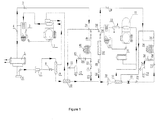
- Figure 1 is a structural diagram of a switchable two-stage and cascade marine energy-saving ultralow-temperature refrigeration system of the present invention as well as a specific embodiment of the present invention.
- sixth solenoid valve 29. low-temperature level air cooler; 30. seventh solenoid valve; 31. expansion vessel; 32. low-temperature level compressor; 33. precooler; 34. eighth solenoid valve; 35. second oil separator; 36. ninth solenoid valve; 37. condensation evaporator; 38. fifth check valve; 39. sixth check valve; 40. tenth solenoid valve; and 41. high-temperature level air cooler.
- the depicted embodiment of the switchable two-stage and cascade marine energy-saving ultralow-temperature refrigeration system of the present invention comprises a high-temperature level refrigeration system, a low-temperature level refrigeration system, a hot fluorine defrosting system of a high-temperature level air cooler and a hot fluorine defrosting system of a low-temperature level air cooler whereby the high-temperature level refrigeration system is also a stand-alone two-stage refrigeration system;
- the high-temperature level refrigeration system comprises a high-temperature level compressor 1, a first oil separator 2, a second solenoid valve 4, a water-cooling condenser 5, a liquid receiver 6, a high-temperature level drying filter 7, a first electronic expansion valve 8, an intercooler 9, a first heat regenerator 10, a fourth solenoid valve 17, a second electronic expansion valve 16, a second check valve 15, a high-temperature level air cooler 41, a tenth solenoid valve 40, a sixth check valve 39, a fifth sole
- the low-temperature level refrigeration system comprises a low-temperature level compressor 32, a precooler 33, a second oil separator 35, a ninth solenoid valve 36, a condensation evaporator 37, a low-temperature level drying filter 20, a second heat regenerator 21, a liquid lens 22, a fourth electronic expansion valve 23, a fourth check valve 27, a low-temperature level air cooler 29, a seventh solenoid valve 30 and an expansion vessel 31 which are connected on a pipeline; an outlet of the low-temperature level compressor 32 is connected with an inlet of the second oil separator 35 through the precooler 33; the outlet of the second oil separator 35 is divided into two paths; the first path is connected with a high-temperature passage of the condensation evaporator 37 through the ninth solenoid valve 36; the high-temperature passage of the condensation evaporator 37 is connected with the low-temperature level drying filter 20; the outlet of the low-temperature level drying filter 20 is connected with one inlet of the second heat regenerator 21; and one outlet of the second heat
- the hot fluorine defrosting system of the high-temperature level air cooler comprises a high-temperature level compressor 1, a first oil separator 2, a first solenoid valve 3, a high-temperature level air cooler 41, a third solenoid valve 14, a first pressure relief valve 13, a first gas-liquid separator 12, a first check valve 11 and a first heat regenerator 10 which are connected on a pipeline;
- the outlet of the high-temperature level compressor 1 is connected with the inlet of the first oil separator 2;
- the outlet of the first oil separator 2 is divided into two paths;
- the second path is connected with the first gas-liquid separator 12 through the first solenoid valve 3, the high-temperature level air cooler 41, the third solenoid valve 14 and the first pressure relief valve 13;
- the outlet of the first gas-liquid separator 12 is connected with the high-temperature level compressor through the first check valve 11 and the first heat regenerator 10.
- the hot fluorine defrosting system of the low-temperature level air cooler comprises a low-temperature level compressor 32, a precooler 33, a second oil separator 35, an eighth solenoid valve 34, a low-temperature level air cooler 29, a sixth solenoid valve 28, a second pressure relief valve 26, a second gas-liquid separator 25, a third check valve 24, a second heat regenerator 21 and an expansion vessel 31 which are connected on a pipeline;
- the outlet of the low-temperature level compressor 32 is connected with the inlet of the second oil separator 35 through the precooler 33;
- the outlet of the second oil separator 35 is divided into two paths;
- the second path is connected with the second gas-liquid separator 25 through the eighth solenoid valve 34, the low-temperature level air cooler 29, the sixth solenoid valve 28 and the second pressure relief valve 26; and the outlet of the second gas-liquid separator 25 is connected with the low-temperature level compressor 32 through the third check valve 24 and the second heat regenerator 21.
- the working process of the high-temperature level refrigeration system is as follows: closing the first solenoid valve 3; opening the second solenoid valve 4; starting the high-temperature level compressor 1; discharging R404A vapor from the high-temperature level compressor 1 to form high-temperature and high-pressure vapor which enters the first oil separator 2; separating lubricating oil from the refrigerant; entering, by the refrigerant vapor, the water-cooling condenser 5; condensing the refrigerant vapor in the water-cooling condenser 5 into a liquid refrigerant; and then, dividing into two paths through the liquid receiver 6 and the high-temperature level drying filter 7, wherein one path is communicated with the intercooler 9 through the first electronic expansion valve 8 and the other path is directly communicated with the intercooler 9; the intercooler 9 has a liquid refrigerant outlet and a gaseous refrigerant outlet; the gaseous refrigerant enters a high-pressure cylinder after mixed with
- switching from the two-stage compression refrigeration system to the cascade refrigeration system can be realized by starting/stopping the corresponding solenoid valve, and the switching process is as follows: on the premise of normal operation of the high-temperature level refrigeration system, opening the fifth solenoid valve 19, closing the fourth solenoid valve 17, starting the low-temperature level refrigeration system, finishing evaporation by the R404A liquid refrigerant in the condensation evaporator 37 and providing cooling amount for R23 condensation.
- the working process of the low-temperature level refrigeration system is as follows: closing the eighth solenoid valve 34; opening the ninth solenoid valve 36; starting the high-temperature level compressor 32; discharging R23 vapor from the low-temperature level compressor 32 to form high-temperature and high-pressure vapor which enters the precooler 33 for precooling and releasing heat; then entering the second oil separator 35; separating lubricating oil from the refrigerant, wherein the refrigerant vapor enters the high-temperature passage of the condensation evaporator 37 and is condensed by the R404A liquid refrigerant in the low-temperature passage, and then enters the second heat regenerator 21 through the low-temperature level drying filter 20 and is supercooled and released with heat; and the supercooled R23 liquid refrigerant enters the low-temperature level air cooler 29 for evaporation and heat absorption through the liquid lens 22, the fourth electronic expansion valve 23 and the fourth check valve 27 for realizing refrigeration of the low-temperature level air cooler 29, thereby
- the hot fluorine defrosting loop of the air cooler enables the high-temperature and high-pressure gas discharged from the compressor to directly pass through a heat exchanger of the air cooler for melting a frost layer coagulated thereon so as to realize the purpose of defrosting. Because the high-temperature and high-pressure gas is heated in the heat exchanger of the air cooler, the defrosting system has short defrosting time, low power consumption, safety and reliability.
- the high-temperature level refrigeration system performs defrosting as follows: starting the first solenoid valve 3; closing the second solenoid valve 4; closing the tenth solenoid valve 40; starting the third solenoid valve 14; closing a motor of the high-temperature level air cooler 41; and starting the high-temperature level variable frequency screw compressor 1, wherein R404A vapor enters the high-temperature level variable frequency screw compressor 1 to form high-temperature and high-pressure vapor and enters the oil separator 2; separating lubricating oil from the refrigerant, wherein the refrigerant vapor enters the high-temperature level air cooler 41 through the first solenoid valve 3 for liquidizing, absorbing heat and beginning to defrost, and the R404A liquid refrigerant enters the high-temperature level variable frequency screw compressor 1 in a gaseous form after passing through the third solenoid valve 14, the first pressure relief valve 13, the first gas-liquid separator 12 and the first pressure relief valve 11.
- the low-temperature level refrigeration system performs defrosting as follows: starting the eighth solenoid valve 34; closing the ninth solenoid valve 36; closing the seventh solenoid valve 30; starting the sixth solenoid valve 28; starting the low-temperature level variable frequency screw compressor 32; and closing a motor of the low-temperature level air cooler 29, wherein R23 vapor enters the low-temperature level variable frequency screw compressor 32 to form high-temperature and high-pressure vapor, and enters the oil separator 35 through the precooler 33; and separating lubricating oil from the refrigerant, wherein the refrigerant vapor enters the low-temperature level air cooler 29 through the eighth solenoid valve 34 for liquidizing, absorbing heat and beginning to defrost, and the R23 liquid refrigerant enters the low-temperature level variable frequency screw compressor 32 in a gaseous form after passing through the sixth solenoid valve 28, the second pressure relief valve 26, the first gas-liquid separator 25 and the third pressure relief valve 24.
- the present invention has the operation features: in a refrigeration process, different refrigeration systems can be switched according to different needs of evaporating temperature; the refrigerating effect is good; temperature control is precise. Meanwhile, the present invention also conforms to the starting feature of a conventional cascade refrigeration system. That is, a high-temperature portion is first started; when the evaporating temperature of the high-temperature portion is decreased enough to ensure that the condensing pressure of a low-temperature portion does not exceed an allowable maximum safely pressure value, the low-temperature portion is started; and in a defrosting process, to ensure safe operation of the system, a loop contrary to the refrigeration loop is adopted for operation.
- the high-temperature and high-pressure refrigerant vapor enters from the outlet of the refrigerant vapor of the air cooler, and the liquid refrigerant leaves from the liquid refrigerant inlet of the air cooler after absorbing heat and liquidizing and enters the air suction port of the compressor through the pressure relief valve and the gas-liquid separator, thereby avoiding generating an air hammer phenomenon.
- a switchable two-stage and cascade marine energy-saving ultralow-temperature refrigeration system of the present invention has the obvious advantages of energy saving and high efficiency in the aspects of improving the problem of narrow section of refrigeration temperature of the cascade refrigeration system.
Landscapes
- Engineering & Computer Science (AREA)
- Mechanical Engineering (AREA)
- Thermal Sciences (AREA)
- Physics & Mathematics (AREA)
- General Engineering & Computer Science (AREA)
- Chemical & Material Sciences (AREA)
- Analytical Chemistry (AREA)
- Power Engineering (AREA)
- Combustion & Propulsion (AREA)
- Ocean & Marine Engineering (AREA)
- Devices That Are Associated With Refrigeration Equipment (AREA)
- Heat-Exchange Devices With Radiators And Conduit Assemblies (AREA)
- Defrosting Systems (AREA)
Description
- The present invention belongs to the technical field of refrigeration and low temperature, and relates to a switchable two-stage and cascade marine energy-saving ultralow-temperature refrigeration system.
- A two-stage compression refrigeration system conducts a compression process in two stages, i.e., increasing intermediate pressure between condensing pressure and evaporating pressure; and low-voltage refrigerant vapor from an evaporator is firstly compressed from evaporating pressure at a low-pressure stage of the compressor into appropriate intermediate pressure, then enters a high-pressure stage after being intercooled, and is compressed again from the intermediate pressure into the condensing pressure, thereby forming two-stage compression. A cascade refrigeration system consists of two refrigeration systems, respectively known as a high-temperature portion and a low-temperature portion. The high-temperature portion uses an intermediate pressure refrigerant and the low-temperature portion uses a low-temperature and high-pressure refrigerant. An overlapped device of the high-temperature portion and the low-temperature portion is a condensation evaporator which is an evaporator of the high-temperature portion as well as a condenser of the low-temperature portion. In the condensation evaporator, an intermediate temperate refrigerant of the high-temperature portion performs vaporization and heat absorption for condensation of the refrigerant of the low-temperature portion.
- In refrigeration engineering, when evaporating temperature reaches a temperature below -25°C, only a small refrigeration device still adopts a single-stage compression refrigeration system in order to simplify the system, but the minimum temperature can only reach -40°C. In a large system for, e.g., freezing processing of food, when the evaporating temperature of -30°C to -60°C is prepared, a two-stage compression refrigeration system is generally used; and when the evaporating temperature of - 60°C to -80°C is required to be prepared, the two-stage compression refrigeration system often cannot satisfy the requirement due to the limitation of such factors as refrigerant solidifying point, system pressure ratio, evaporating pressure, operational economics, etc. At this moment, a cascade refrigeration system is required to be adopted. That is: the evaporating temperature of the two-stage compression refrigeration system is generally regulated as -30°C to -60°C, and the evaporating temperature of the cascade refrigeration system is generally regulated as -50°C to -80°C.
- To extend a section of refrigeration temperature of the cascade refrigeration system, a patent documentation with the publication No. of
CN202973641U discloses a -80°C series-parallel automatic switching cascade refrigeration system which comprises a high-temperature level refrigeration system and a low-temperature level refrigeration system. An outlet of a high-temperature level compressor is communicated with a liquid storage tank through a high-temperature condenser; an outlet of the liquid storage tank is divided into two paths through a drying filter; an outlet of the low-temperature level compressor is divided into two paths; one path of an outlet of an expansion vessel is communicated with an inlet of the low-temperature level compressor; the other path is communicated with a low-temperature evaporator through a tubular exchanger; and an outlet of the low-temperature evaporator is communicated with an inlet of the low-temperature level compressor through an oil separator. The system during operation respectively realizes temperature control of high-temperature level refrigeration (room temperature to -40°C) and low-temperature level refrigeration (-40°C to -80°C) by switching solenoid valves, so as to realize temperature control from room temperature to -80°C, thereby obtaining large scope of refrigeration section, increasing the operating efficiency of the compressor and reducing operating cost. However, because the high-temperature level of the above refrigeration system adopts the single-stage compression refrigeration system, as mentioned previously, in the refrigeration engineering, when the evaporating temperature is below -25°C, corresponding evaporating pressure is also low and the pressure ratio pk/po is too large, often leading to greater deviation of an actual compression process of the compressor from an isentropic degree, thereby increasing actual power consumption of the compressor and decreasing the efficiency; overlarge pressure ratio may also result in an increase in exhaust gas temperature of the compressor, while overhigh exhaust gas temperature will result in thinning and even carbonization of lubricating oil. Therefore, the single-stage compression refrigeration system is not adopted. - At present, a conventional defrosting mode of an air cooler is to adopt traditional electrical heating for defrosting. Defrosting time is controlled by a defrosting controller, and an electrical heating wire generates radiant heat for melting a frost layer. Such a method has the disadvantages: a defrosting system consumes large power; moreover, an electrical heating system has many elements; defrosting is inadequate so that the safety of a product is reduced. In practical situations, large fluctuation of storehouse temperature is often caused, and the storage quality of the food is affected.
- The present invention provides a switchable two-stage and cascade marine energy-saving ultralow-temperature refrigeration system according to claim 1 and comprises: a high-temperature level refrigeration system, a low-temperature level refrigeration system, wherein the high-temperature level refrigeration system is also a stand-alone two-stage refrigeration system; the high-temperature level refrigeration system and the low-temperature level refrigeration system are thermally coupled via a condensation evaporator; the high-temperature level refrigeration system comprises a high-temperature level compressor with a low pressure stage and a high pressure stage, the low pressure stage and the high pressure stage being connected as two sequential compression steps, a first oil separator, a second solenoid valve, a water-cooling condenser, a liquid receiver, a high-temperature level drying filter, a first electronic expansion valve, an intercooler, a first heat regenerator, a fourth solenoid valve, a second electronic expansion valve, a second check valve, a high-temperature level air cooler, a tenth solenoid valve, a sixth check valve, a fifth solenoid valve, a third electronic expansion valve, and a fifth check valve which are connected on a pipeline; an outlet of the high pressure stage of the high-temperature level compressor is connected with an inlet of the first oil separator; the outlet of the first oil separator is divided into two paths; the first path is connected with an inlet of the water-cooling condenser through the second solenoid valve; an outlet of the water-cooling condenser is connected with the liquid receiver; an outlet of the liquid receiver is connected with an inlet of the high-temperature level drying filter; an outlet of the high-temperature level drying filter is divided into two paths; the first path is communicated with the inlet of the high pressure stage of the high-temperature level compressor through the first electronic expansion valve and the intercooler; the second path is connected with one inlet of the first heat regenerator through the intercooler; one outlet of the first heat regenerator is divided into two paths; the first path is connected with the high-temperature level air cooler through the fourth solenoid valve, the second electronic expansion valve and the second check valve; the high-temperature level air cooler is connected with the inlet of the high pressure stage of the high-temperature level compressor through the tenth solenoid valve, the sixth check valve and the first heat regenerator; the second path is connected with a low-temperature passage of the condensation evaporator through the fifth solenoid valve and the third electronic expansion valve; and an outlet of the low-temperature passage of the condensation evaporator is connected with the inlet of the high pressure stage of the high-temperature level compressor through the fifth check valve and the first heat regenerator.
- The low-temperature level refrigeration system comprises a low-temperature level compressor, a precooler, a second oil separator, a ninth solenoid valve, a low-temperature level drying filter, a second heat regenerator, a liquid lens, a fourth electronic expansion valve, a fourth check valve, a low-temperature level air cooler, a seventh solenoid valve and an expansion vessel which are connected on a pipeline; an outlet of the low-temperature level compressor is connected with an inlet of the second oil separator through the precooler; the outlet of the second oil separator is divided into two paths; the first path is connected with a high-temperature passage of the condensation evaporator through the ninth solenoid valve; the high-temperature passage of the condensation evaporator is connected with the low-temperature level drying filter; the outlet of the low-temperature level drying filter is connected with one inlet of the second heat regenerator; and one outlet of the second heat regenerator is connected with the low-temperature level compressor through the liquid lens, the fourth electronic expansion valve, the fourth check valve, the low-temperature level air cooler and the seventh solenoid valve.
- The high-temperature level compressor and the low-temperature level compressor are variable frequency screw compressors and can realize continuative energy regulation so that the system has high efficiency and energy saving.
- The high-temperature level refrigeration system is a stand-alone two-stage refrigeration system and can be used as an independent refrigeration system.
- In the high-temperature level refrigeration system, the fifth solenoid valve is started and the fourth solenoid valve is closed for realizing switching from the two-stage compression refrigeration system to the cascade compression refrigeration system.
- An embodiment according to the current invention of the switchable two-stage and cascade marine energy-saving ultralow-temperature refrigeration system is that the condensation evaporator is a plate type heat exchanger.
- An embodiment according to the current invention of the switchable two-stage and cascade marine energy-saving ultralow-temperature refrigeration system is that a refrigerant R404A is applied to the high-temperature level refrigeration system and a refrigerant R23 is applied to the low-temperature level refrigeration system.
- In combination with the above features, the switchable two-stage and cascade marine energy-saving ultralow-temperature refrigeration system of the present invention realizes switching from the two-stage compression refrigeration system to the cascade refrigeration system by starting/stopping the corresponding solenoid valve so as to effectively expand a section of refrigeration temperature of the cascade refrigeration system, achieve continuous regulation within a section of evaporating temperature of -30°C to -80°C and enhance the performance of the system. The present invention has the advantages of stable operation and obvious energy saving effect.
-
Figure 1 is a structural diagram of a switchable two-stage and cascade marine energy-saving ultralow-temperature refrigeration system of the present invention as well as a specific embodiment of the present invention. - In the drawings: 1. high-temperature level compressor; 2. first oil separator; 3. first solenoid valve; 4. second solenoid valve; 5. water-cooling condenser; 6. liquid receiver; 7. high-temperature level drying filter; 8. first electronic expansion valve; 9. intercooler; 10. first heat regenerator; 11. first check valve; 12. first gas-liquid separator; 13. first pressure relief valve; 14. third solenoid valve; 15. second check valve; 16. second electronic expansion valve; 17. fourth solenoid valve; 18. third electronic expansion valve; 19. fifth solenoid valve; 20. low-temperature level drying filter; 21. second heat regenerator; 22. liquid lens; 23. fourth electronic expansion valve; 24. third check valve; 25. second gas-liquid separator; 26. second pressure relief valve; 27. fourth check valve; 28. sixth solenoid valve; 29. low-temperature level air cooler; 30. seventh solenoid valve; 31. expansion vessel; 32. low-temperature level compressor; 33. precooler; 34. eighth solenoid valve; 35. second oil separator; 36. ninth solenoid valve; 37. condensation evaporator; 38. fifth check valve; 39. sixth check valve; 40. tenth solenoid valve; and 41. high-temperature level air cooler.
- To easily understand the operation flow and the creative feature realized by the present invention, the present invention is further elaborated below in combination with specific embodiments.
- As shown in
Figure 1 , the depicted embodiment of the switchable two-stage and cascade marine energy-saving ultralow-temperature refrigeration system of the present invention comprises a high-temperature level refrigeration system, a low-temperature level refrigeration system, a hot fluorine defrosting system of a high-temperature level air cooler and a hot fluorine defrosting system of a low-temperature level air cooler whereby the high-temperature level refrigeration system is also a stand-alone two-stage refrigeration system; the high-temperature level refrigeration system comprises a high-temperature level compressor 1, a first oil separator 2, a second solenoid valve 4, a water-cooling condenser 5, a liquid receiver 6, a high-temperature level drying filter 7, a first electronic expansion valve 8, an intercooler 9, a first heat regenerator 10, a fourth solenoid valve 17, a second electronic expansion valve 16, a second check valve 15, a high-temperature level air cooler 41, a tenth solenoid valve 40, a sixth check valve 39, a fifth solenoid valve 19, a third electronic expansion valve 18, a condensation evaporator 37 and a fifth check valve 38 which are connected on a pipeline; an outlet of the high-temperature level compressor 1 is connected with an inlet of the first oil separator 2; the outlet of the first oil separator 2 is divided into two paths; the first path is connected with an inlet of the water-cooling condenser 5 through the second solenoid valve 4; an outlet of the water-cooling condenser 5 is connected with the liquid receiver 6; an outlet of the liquid receiver 6 is connected with an inlet of the high-temperature level drying filter 7; an outlet of the high-temperature level drying filter 7 is divided into two paths; the first path is communicated with the high-temperature level compressor 1 through the first electronic expansion valve 8 and the intercooler 9; the second path is connected with one inlet of the first heat regenerator 10 through the intercooler 9; one outlet of the first heat regenerator 10 is divided into two paths; the first path is connected with the high-temperature level air cooler 41 through the fourth solenoid valve 17, the second electronic expansion valve 16 and the second check valve 15; the high-temperature level air cooler 41 is connected with the high-temperature level compressor 1 through the tenth solenoid valve 40, the sixth check valve 39 and the first heat regenerator 10; the second path is connected with a low-temperature passage of the condensation evaporator 37 through the fifth solenoid valve 19 and the third electronic expansion valve 18; and an outlet of the low-temperature passage of the condensation evaporator 37 is connected with the high-temperature level compressor 1 through the fifth check valve 38 and the first heat regenerator 10. - The low-temperature level refrigeration system comprises a low-temperature level compressor 32, a precooler 33, a second oil separator 35, a ninth solenoid valve 36, a condensation evaporator 37, a low-temperature level drying filter 20, a second heat regenerator 21, a liquid lens 22, a fourth electronic expansion valve 23, a fourth check valve 27, a low-temperature level air cooler 29, a seventh solenoid valve 30 and an expansion vessel 31 which are connected on a pipeline; an outlet of the low-temperature level compressor 32 is connected with an inlet of the second oil separator 35 through the precooler 33; the outlet of the second oil separator 35 is divided into two paths; the first path is connected with a high-temperature passage of the condensation evaporator 37 through the ninth solenoid valve 36; the high-temperature passage of the condensation evaporator 37 is connected with the low-temperature level drying filter 20; the outlet of the low-temperature level drying filter 20 is connected with one inlet of the second heat regenerator 21; and one outlet of the second heat regenerator 21 is connected with the low-temperature level compressor 32 through the liquid lens 22, the fourth electronic expansion valve 23, the fourth check valve 27, the low-temperature level air cooler 29 and the seventh solenoid valve 30.
- The hot fluorine defrosting system of the high-temperature level air cooler comprises a high-temperature level compressor 1, a first oil separator 2, a
first solenoid valve 3, a high-temperaturelevel air cooler 41, athird solenoid valve 14, a firstpressure relief valve 13, a first gas-liquid separator 12, a first check valve 11 and afirst heat regenerator 10 which are connected on a pipeline; the outlet of the high-temperature level compressor 1 is connected with the inlet of the first oil separator 2; the outlet of the first oil separator 2 is divided into two paths; the second path is connected with the first gas-liquid separator 12 through thefirst solenoid valve 3, the high-temperaturelevel air cooler 41, thethird solenoid valve 14 and the firstpressure relief valve 13; and the outlet of the first gas-liquid separator 12 is connected with the high-temperature level compressor through the first check valve 11 and thefirst heat regenerator 10. - The hot fluorine defrosting system of the low-temperature level air cooler comprises a low-
temperature level compressor 32, aprecooler 33, asecond oil separator 35, aneighth solenoid valve 34, a low-temperaturelevel air cooler 29, asixth solenoid valve 28, a secondpressure relief valve 26, a second gas-liquid separator 25, a third check valve 24, asecond heat regenerator 21 and anexpansion vessel 31 which are connected on a pipeline; the outlet of the low-temperature level compressor 32 is connected with the inlet of thesecond oil separator 35 through theprecooler 33; the outlet of thesecond oil separator 35 is divided into two paths; the second path is connected with the second gas-liquid separator 25 through theeighth solenoid valve 34, the low-temperaturelevel air cooler 29, thesixth solenoid valve 28 and the secondpressure relief valve 26; and the outlet of the second gas-liquid separator 25 is connected with the low-temperature level compressor 32 through the third check valve 24 and thesecond heat regenerator 21. - The working process of the high-temperature level refrigeration system is as follows: closing the first solenoid valve 3; opening the second solenoid valve 4; starting the high-temperature level compressor 1; discharging R404A vapor from the high-temperature level compressor 1 to form high-temperature and high-pressure vapor which enters the first oil separator 2; separating lubricating oil from the refrigerant; entering, by the refrigerant vapor, the water-cooling condenser 5; condensing the refrigerant vapor in the water-cooling condenser 5 into a liquid refrigerant; and then, dividing into two paths through the liquid receiver 6 and the high-temperature level drying filter 7, wherein one path is communicated with the intercooler 9 through the first electronic expansion valve 8 and the other path is directly communicated with the intercooler 9; the intercooler 9 has a liquid refrigerant outlet and a gaseous refrigerant outlet; the gaseous refrigerant enters a high-pressure cylinder after mixed with the refrigerant discharged from a low-pressure cylinder of the high-temperature level compressor 1; the liquid refrigerant enters the first heat regenerator 10 and is supercooled by the R404A vapor from the high-temperature level air cooler; and the supercooled liquid refrigerant enters the high-temperature level air cooler 41 through the fourth solenoid valve 17, the second electronic expansion valve 16 and the second check valve 15 for realizing refrigeration of the high-temperature level air cooler.
- According to a difference in setting of refrigeration temperature, switching from the two-stage compression refrigeration system to the cascade refrigeration system can be realized by starting/stopping the corresponding solenoid valve, and the switching process is as follows: on the premise of normal operation of the high-temperature level refrigeration system, opening the
fifth solenoid valve 19, closing thefourth solenoid valve 17, starting the low-temperature level refrigeration system, finishing evaporation by the R404A liquid refrigerant in thecondensation evaporator 37 and providing cooling amount for R23 condensation. - The working process of the low-temperature level refrigeration system is as follows: closing the
eighth solenoid valve 34; opening the ninth solenoid valve 36; starting the high-temperature level compressor 32; discharging R23 vapor from the low-temperature level compressor 32 to form high-temperature and high-pressure vapor which enters theprecooler 33 for precooling and releasing heat; then entering thesecond oil separator 35; separating lubricating oil from the refrigerant, wherein the refrigerant vapor enters the high-temperature passage of thecondensation evaporator 37 and is condensed by the R404A liquid refrigerant in the low-temperature passage, and then enters thesecond heat regenerator 21 through the low-temperaturelevel drying filter 20 and is supercooled and released with heat; and the supercooled R23 liquid refrigerant enters the low-temperaturelevel air cooler 29 for evaporation and heat absorption through the liquid lens 22, the fourth electronic expansion valve 23 and thefourth check valve 27 for realizing refrigeration of the low-temperaturelevel air cooler 29, thereby achieving continuous regulation of evaporating temperature of the switchable two-stage and cascade marine energy-saving ultralow-temperature refrigeration system at -30°C to -80°C. - The hot fluorine defrosting loop of the air cooler enables the high-temperature and high-pressure gas discharged from the compressor to directly pass through a heat exchanger of the air cooler for melting a frost layer coagulated thereon so as to realize the purpose of defrosting. Because the high-temperature and high-pressure gas is heated in the heat exchanger of the air cooler, the defrosting system has short defrosting time, low power consumption, safety and reliability.
- The high-temperature level refrigeration system performs defrosting as follows: starting the
first solenoid valve 3; closing the second solenoid valve 4; closing thetenth solenoid valve 40; starting thethird solenoid valve 14; closing a motor of the high-temperaturelevel air cooler 41; and starting the high-temperature level variable frequency screw compressor 1, wherein R404A vapor enters the high-temperature level variable frequency screw compressor 1 to form high-temperature and high-pressure vapor and enters the oil separator 2; separating lubricating oil from the refrigerant, wherein the refrigerant vapor enters the high-temperaturelevel air cooler 41 through thefirst solenoid valve 3 for liquidizing, absorbing heat and beginning to defrost, and the R404A liquid refrigerant enters the high-temperature level variable frequency screw compressor 1 in a gaseous form after passing through thethird solenoid valve 14, the firstpressure relief valve 13, the first gas-liquid separator 12 and the first pressure relief valve 11. - The low-temperature level refrigeration system performs defrosting as follows: starting the
eighth solenoid valve 34; closing the ninth solenoid valve 36; closing theseventh solenoid valve 30; starting thesixth solenoid valve 28; starting the low-temperature level variablefrequency screw compressor 32; and closing a motor of the low-temperaturelevel air cooler 29, wherein R23 vapor enters the low-temperature level variablefrequency screw compressor 32 to form high-temperature and high-pressure vapor, and enters theoil separator 35 through theprecooler 33; and separating lubricating oil from the refrigerant, wherein the refrigerant vapor enters the low-temperaturelevel air cooler 29 through theeighth solenoid valve 34 for liquidizing, absorbing heat and beginning to defrost, and the R23 liquid refrigerant enters the low-temperature level variablefrequency screw compressor 32 in a gaseous form after passing through thesixth solenoid valve 28, the secondpressure relief valve 26, the first gas-liquid separator 25 and the third pressure relief valve 24. - The present invention has the operation features: in a refrigeration process, different refrigeration systems can be switched according to different needs of evaporating temperature; the refrigerating effect is good; temperature control is precise. Meanwhile, the present invention also conforms to the starting feature of a conventional cascade refrigeration system. That is, a high-temperature portion is first started; when the evaporating temperature of the high-temperature portion is decreased enough to ensure that the condensing pressure of a low-temperature portion does not exceed an allowable maximum safely pressure value, the low-temperature portion is started; and in a defrosting process, to ensure safe operation of the system, a loop contrary to the refrigeration loop is adopted for operation. That is, the high-temperature and high-pressure refrigerant vapor enters from the outlet of the refrigerant vapor of the air cooler, and the liquid refrigerant leaves from the liquid refrigerant inlet of the air cooler after absorbing heat and liquidizing and enters the air suction port of the compressor through the pressure relief valve and the gas-liquid separator, thereby avoiding generating an air hammer phenomenon.
- Known from the above analysis, a switchable two-stage and cascade marine energy-saving ultralow-temperature refrigeration system of the present invention has the obvious advantages of energy saving and high efficiency in the aspects of improving the problem of narrow section of refrigeration temperature of the cascade refrigeration system.
Claims (6)
- A switchable two-stage and cascade marine energy-saving ultralow-temperature refrigeration system, comprising a high-temperature level refrigeration system, a low-temperature level refrigeration system, wherein:(1) the high-temperature level refrigeration system is a stand-alone two-stage refrigeration system;(2) the high-temperature level refrigeration system and the low-temperature level refrigeration system are thermally coupled via a condensation evaporator (37);(3) the high-temperature level refrigeration system comprises a high-temperature level compressor (1) with a low pressure stage and a high pressure stage, the low pressure stage and the high pressure stage being connected as two sequential compression steps, a first oil separator (2), a second solenoid valve (4), a water-cooling condenser (5), a liquid receiver (6), a high-temperature level drying filter (7), a first electronic expansion valve (8), an intercooler (9), a first heat regenerator (10), a fourth solenoid valve (17), a second electronic expansion valve (16), a second check valve (15), a high-temperature level air cooler (41), a tenth solenoid valve (40), a sixth check valve (39), a fifth solenoid valve (19), a third electronic expansion valve (18), and a fifth check valve (38) which are connected on a pipeline;(4) an outlet of the high pressure stage of the high-temperature level compressor (1) is connected with an inlet of the first oil separator (2); the outlet of the first oil separator (2) is divided into two paths; the first path is connected with an inlet of the water-cooling condenser (5) through the second solenoid valve (4); an outlet of the water-cooling condenser (5) is connected with the liquid receiver (6); an outlet of the liquid receiver (6) is connected with an inlet of the high-temperature level drying filter (7); an outlet of the high-temperature level drying filter (7) is divided into two paths; the first path is communicated with the inlet of the high pressure stage of the high-temperature level compressor (1) through the first electronic expansion valve (8) and the intercooler (9); the second path is connected with one inlet of the first heat regenerator (10) through the intercooler (9); one outlet of the first heat regenerator (10) is divided into two paths; the first path is connected with the high-temperature level air cooler (41) through the fourth solenoid valve (17), the second electronic expansion valve (16) and the second check valve (15); the high-temperature level air cooler (41) is connected with the inlet of the low pressure stage of the high-temperature level compressor (1) through the tenth solenoid valve (40), the sixth check valve (39) and the first heat regenerator (10); the second path is connected with a low-temperature passage of the condensation evaporator (37) through the fifth solenoid valve (19) and the third electronic expansion valve (18); and an outlet of the low-temperature passage of the condensation evaporator (37) is connected with the inlet of the low pressure stage of the high-temperature level compressor (1) through the fifth check valve (38) and the first heat regenerator (10);(5) the low-temperature level refrigeration system comprises a low-temperature level compressor (32), a precooler (33), a second oil separator (35), a ninth solenoid valve (36), a low-temperature level drying filter (20), a second heat regenerator (21), a liquid lens (22), a fourth electronic expansion valve (23), a fourth check valve (27), a low-temperature level air cooler (29), a seventh solenoid valve (30) and an expansion vessel (31) which are connected on a pipeline;(6) an outlet of the low-temperature level compressor (32) is connected with an inlet of the second oil separator (35) through the precooler (33); the outlet of the second oil separator (35) is divided into two paths; the first path is connected with a high-temperature passage of the condensation evaporator (37) through the ninth solenoid valve (36); the high-temperature passage of the condensation evaporator (37) is connected with the low-temperature level drying filter (20); the outlet of the low-temperature level drying filter (20) is connected with one inlet of the second heat regenerator (21); and one outlet of the second heat regenerator (21) is connected with the low-temperature level compressor (32) through the liquid lens (22), the fourth electronic expansion valve (23), the fourth check valve (27), the low-temperature level air cooler (29) and the seventh solenoid valve (30);
- The switchable two-stage and cascade marine energy-saving ultralow-temperature refrigeration system according to claim 1, wherein the high-temperature level compressor (1) and the low-temperature level compressor (32) are variable frequency screw compressors.
- The switchable two-stage and cascade marine energy-saving ultralow-temperature refrigeration system according to claim 1, wherein the high-temperature level refrigeration system is the stand-alone two-stage refrigeration system and can be used as an independent refrigeration system.
- The switchable two-stage and cascade marine energy-saving ultralow-temperature refrigeration system according to claim 1, wherein the high-temperature level refrigeration system, the fifth solenoid valve (19) is started and the fourth solenoid valve (17) is closed for realizing switching from the two-stage compression refrigeration system to the cascade compression refrigeration system.
- The switchable two-stage and cascade marine energy-saving ultralow-temperature refrigeration system according to claim 1, wherein the condensation evaporator (37) is a plate type heat exchanger.
- The switchable two-stage and cascade marine energy-saving ultralow-temperature refrigeration system according to claim 1, wherein a refrigerant R404A is applied to the high-temperature level refrigeration system and a refrigerant R23 is applied to the low-temperature level refrigeration system.
Applications Claiming Priority (2)
| Application Number | Priority Date | Filing Date | Title |
|---|---|---|---|
| CN201510236044.9A CN104807231A (en) | 2015-05-12 | 2015-05-12 | Switchable two-stage cascade energy-saving ultralow-temperature refrigeration system for ship |
| PCT/CN2015/097554 WO2016180021A1 (en) | 2015-05-12 | 2015-12-16 | Switchable two-stage cascade energy-saving ultralow-temperature refrigeration system for ship |
Publications (3)
| Publication Number | Publication Date |
|---|---|
| EP3299747A1 EP3299747A1 (en) | 2018-03-28 |
| EP3299747A4 EP3299747A4 (en) | 2019-01-23 |
| EP3299747B1 true EP3299747B1 (en) | 2020-02-12 |
Family
ID=53692284
Family Applications (1)
| Application Number | Title | Priority Date | Filing Date |
|---|---|---|---|
| EP15881416.0A Active EP3299747B1 (en) | 2015-05-12 | 2015-12-16 | Switchable two-stage cascade energy-saving ultralow-temperature refrigeration system for ships |
Country Status (5)
| Country | Link |
|---|---|
| US (1) | US10107526B2 (en) |
| EP (1) | EP3299747B1 (en) |
| JP (1) | JP6216077B2 (en) |
| CN (1) | CN104807231A (en) |
| WO (1) | WO2016180021A1 (en) |
Families Citing this family (69)
| Publication number | Priority date | Publication date | Assignee | Title |
|---|---|---|---|---|
| CN208443069U (en) * | 2015-01-09 | 2019-01-29 | 特灵国际有限公司 | heat pump system |
| CN104807231A (en) * | 2015-05-12 | 2015-07-29 | 上海海洋大学 | Switchable two-stage cascade energy-saving ultralow-temperature refrigeration system for ship |
| CN104976831A (en) * | 2015-07-30 | 2015-10-14 | 武汉研润科技发展有限公司 | Evaporative condenser of cascade refrigerating machine |
| US10655895B2 (en) * | 2017-05-04 | 2020-05-19 | Weiss Technik North America, Inc. | Climatic test chamber with stable cascading direct expansion refrigeration system |
| CN108954999A (en) * | 2017-05-17 | 2018-12-07 | 上海通用富士冷机有限公司 | Electric expansion valve hot gas defrosting system Condensing units |
| CN107116992B (en) * | 2017-05-27 | 2023-04-07 | 中原工学院 | High-efficient on-vehicle air conditioning system with quick step cooling |
| CN107388613A (en) * | 2017-08-29 | 2017-11-24 | 东莞市伟煌试验设备有限公司 | Superposition type energy-saving refrigerating system |
| CN107796142B (en) * | 2017-11-02 | 2023-07-21 | 珠海格力电器股份有限公司 | Air source heat pump system and control method thereof |
| CN107726656A (en) * | 2017-11-08 | 2018-02-23 | 郑州云宇新能源技术有限公司 | The refrigerant heat pump system of single twin-stage conversion can be carried out |
| CN108088076B (en) * | 2017-12-19 | 2023-10-31 | 云南仨得科技有限公司 | An efficient and intelligent air energy hot air unit and its control method |
| CN108266915A (en) * | 2018-03-05 | 2018-07-10 | 天津商业大学 | It is a kind of to use single working medium CO2Make the cascade refrigeration system of refrigerant |
| CN108266916B (en) * | 2018-03-21 | 2023-11-07 | 天津商业大学 | Multi-cycle variable flow heat pump system |
| CN108378128B (en) * | 2018-04-20 | 2024-03-19 | 浙江青风环境股份有限公司 | A multi-stage temperature and humidity control cooling system |
| CN108716785B (en) * | 2018-07-20 | 2023-09-26 | 天津商业大学 | Refrigeration system with primary throttling, intermediate complete cooling with medium temperature evaporator |
| CN109210816B (en) * | 2018-09-29 | 2024-03-01 | 南京五洲制冷集团有限公司 | Double-heat-source defrosting oil gas recovery unit with refrigerant migration prevention function |
| CN109481000B (en) * | 2018-12-26 | 2023-11-21 | 上海导向医疗系统有限公司 | Pressure-adjustable refrigeration devices and cryotherapy systems for cryotherapy |
| CN110001913B (en) * | 2019-04-19 | 2024-01-12 | 合肥天鹅制冷科技有限公司 | Full-automatic ship refrigerating device based on PLC control system |
| CN110260560B (en) * | 2019-07-19 | 2024-06-11 | 北京金茂绿建科技有限公司 | High-power single-machine two-stage vortex type ultralow-temperature air source heat pump |
| CN110631320A (en) * | 2019-10-31 | 2019-12-31 | 江苏精英冷暖设备工程有限公司 | Hot gas defrosting system |
| CN110701664B (en) * | 2019-11-11 | 2023-05-05 | 江苏天舒电器有限公司 | Wide-ring-temperature multistage water outlet variable-frequency air energy cascade heat engine system and working method thereof |
| CN110749114A (en) * | 2019-11-29 | 2020-02-04 | 大连冰山空调设备有限公司 | A new high-efficiency multi-mode cascade high temperature heat pump unit |
| CN110849009B (en) * | 2019-12-11 | 2023-10-13 | 郑州长城科工贸有限公司 | Cascade refrigeration system and method for reducing starting load thereof |
| CN110920647A (en) * | 2019-12-23 | 2020-03-27 | 甘肃一德新能源设备有限公司 | Sterilization carbon dioxide heat pump locomotive air conditioner cooling unit and use method thereof |
| CN111111251A (en) * | 2020-01-19 | 2020-05-08 | 无锡冠亚恒温制冷技术有限公司 | Gas condensation recovery device |
| CN111735224A (en) * | 2020-01-21 | 2020-10-02 | 天津冷源工程设计院 | Refrigerating system suitable for multiple load working condition |
| US11371756B2 (en) * | 2020-02-27 | 2022-06-28 | Heatcraft Refrigeration Products Llc | Cooling system with oil return to accumulator |
| US11384969B2 (en) * | 2020-02-27 | 2022-07-12 | Heatcraft Refrigeration Products Llc | Cooling system with oil return to oil reservoir |
| CN111375294A (en) * | 2020-04-20 | 2020-07-07 | 中山市凌宇机械有限公司 | Large-scale freezing type drying machine with stepless energy regulation |
| CN111829116B (en) * | 2020-07-27 | 2025-01-14 | 合肥天鹅制冷科技有限公司 | One-for-one air conditioning system |
| CN112066588A (en) * | 2020-09-29 | 2020-12-11 | 深圳市奥科德冷冻系统有限公司 | Reverse recovery type hot defrosting refrigeration system |
| CN114593535B (en) * | 2020-12-07 | 2024-08-09 | 浙江盾安冷链系统有限公司 | Multi-temperature-zone refrigerating and heating integrated system and control method thereof |
| CN112556241B (en) * | 2020-12-21 | 2024-02-20 | 珠海格力电器股份有限公司 | Compressor assembly, control method and air conditioner |
| USD1073892S1 (en) | 2021-01-26 | 2025-05-06 | Dometic Sweden Ab | Air conditioning housing |
| EP4281300A1 (en) | 2021-01-26 | 2023-11-29 | Dometic Sweden AB | Air conditioning system for a vehicle |
| CN112984850A (en) * | 2021-03-23 | 2021-06-18 | 上海理工大学 | Energy-saving high-low temperature environment test box refrigerating system |
| CN113638863A (en) * | 2021-07-20 | 2021-11-12 | 新科环保科技有限公司 | Method for rapidly filling cold oil into multi-split air conditioner and refrigerating system |
| CN114030582B (en) * | 2021-10-19 | 2024-01-26 | 中国舰船研究设计中心 | An integrated engine room seawater cooling system |
| CN113883600B (en) * | 2021-11-01 | 2023-02-10 | 湖北璞瑞斯节能技术服务有限公司 | Air conditioner double-compressor refrigerating system and air conditioner |
| CN114111074B (en) * | 2021-12-01 | 2024-07-16 | 苏州奥德高端装备股份有限公司 | Precise oil-gas dehumidifying device |
| CN114183951B (en) * | 2021-12-16 | 2022-12-09 | 珠海格力电器股份有限公司 | Refrigerant purification recovery device and refrigerant purification system |
| CN114484936B (en) * | 2022-01-05 | 2023-07-21 | 浙江态能动力技术有限公司 | Energy storage operation control system based on ultra-high temperature heat pump |
| CN114353380B (en) * | 2022-01-05 | 2023-02-07 | 浙江态能动力技术有限公司 | Ultrahigh-temperature heat pump energy storage system based on recompression circulation |
| CN114608212A (en) * | 2022-02-25 | 2022-06-10 | 南通亚泰工程技术有限公司 | Cascade refrigerating plant |
| CN114699789B (en) * | 2022-03-16 | 2023-05-09 | 南京都乐制冷设备有限公司 | Oil-gas recovery device for oil tanker wharf |
| CN115031421A (en) * | 2022-04-14 | 2022-09-09 | 江阴市索创工业精密制冷设备有限公司 | Low-temperature skid-mounted refrigerating unit of hydrogenation machine |
| CN114659309B (en) * | 2022-04-20 | 2024-06-28 | 合肥亦威科技有限公司 | Ultralow-temperature high-precision temperature control system |
| CN114777355A (en) * | 2022-04-28 | 2022-07-22 | 浙江中广电器集团股份有限公司 | A new type of ultra-high temperature energy-saving heat pump using EVI technology |
| CN114811551B (en) * | 2022-05-05 | 2025-04-29 | 中际(江苏)智能暖通设备有限公司 | A low pressure steam generator |
| CN115031430B (en) * | 2022-05-31 | 2025-08-05 | 重庆海尔制冷电器有限公司 | Cascade refrigeration system control method, storage medium, system, refrigerator and cold storage |
| CN115164440A (en) * | 2022-06-16 | 2022-10-11 | 青岛海尔电冰箱有限公司 | Refrigerating system and refrigerating equipment |
| CN115096020A (en) * | 2022-06-29 | 2022-09-23 | 上海秀熵能源技术有限公司 | Ultra-high temperature water source heat pump |
| CN115993012B (en) * | 2022-07-15 | 2025-10-17 | 苏州贝茵科技股份有限公司 | Ultralow temperature preservation box based on variable frequency cascade refrigeration system |
| CN115500049A (en) * | 2022-08-03 | 2022-12-20 | 北京无线电测量研究所 | Environment control equipment, environment control system and environment control method |
| CN117553481B (en) * | 2022-08-04 | 2025-11-11 | 青岛海尔特种电冰柜有限公司 | Composite refrigeration system, refrigeration device and control method |
| CN115289709A (en) * | 2022-08-11 | 2022-11-04 | 舟山英诺远投冷链科技有限公司 | Marine carbon dioxide quick-freezing system |
| CN116202238A (en) * | 2022-09-08 | 2023-06-02 | 青岛澳柯玛生物医疗有限公司 | A low-temperature refrigeration system and its control method for preventing oil plugging |
| CN116222013A (en) * | 2023-02-22 | 2023-06-06 | 广东宏阔试验设备有限公司 | Ultralow temperature refrigeration system |
| CN116202256B (en) * | 2023-03-03 | 2025-05-06 | 北京工业大学 | Monitoring and control method of adjustable single screw compressor regenerative cascade low temperature refrigeration system |
| CN116123744B (en) * | 2023-03-24 | 2024-09-20 | 哈尔滨工业大学 | An ultra-low temperature single-stage and double-stage hybrid air source heat pump unit |
| CN116379641A (en) * | 2023-04-03 | 2023-07-04 | 天津商业大学 | A solar and air energy dual heat source cascade heat pump device |
| CN116123747A (en) * | 2023-04-14 | 2023-05-16 | 云南道精制冷科技有限责任公司 | Overlapping type cold and hot source unit |
| CN116951827B (en) * | 2023-06-16 | 2025-09-16 | 约克(无锡)空调冷冻设备有限公司 | Flooded heat exchanger and marine lithium bromide refrigerating unit comprising same |
| CN116678130B (en) * | 2023-07-05 | 2025-05-27 | 合肥天鹅制冷科技有限公司 | Wide-temperature-range refrigerating system with double evaporators and double condensers |
| CN116907130A (en) * | 2023-07-12 | 2023-10-20 | 深圳市弗澜柯制冷设备有限公司 | Ice machine refrigerating system with good refrigerating effect and capable of avoiding oil shortage of compressor |
| CN117847824B (en) * | 2024-01-18 | 2025-07-22 | 中车大连机车研究所有限公司 | Low-temperature-resistant railway vehicle quasi-double-stage compression variable-frequency carbon dioxide heat pump air conditioner |
| CN118532856B (en) * | 2024-06-05 | 2026-01-27 | 西安交通大学 | Spray liquid cooling control method and system for screw compressor motor of two-stage heat pump system |
| CN118328573B (en) * | 2024-06-12 | 2024-10-15 | 无锡冠亚恒温制冷技术有限公司 | Ultralow temperature refrigeration system and control method thereof |
| CN120521322B (en) * | 2025-07-23 | 2025-11-11 | 珠海凌达压缩机有限公司 | A control method and air conditioning system |
| CN120793129B (en) * | 2025-09-03 | 2025-12-09 | 江苏兆胜空调有限公司 | Marine double-cold-source heat energy-saving management and control air conditioning unit |
Family Cites Families (29)
| Publication number | Priority date | Publication date | Assignee | Title |
|---|---|---|---|---|
| US3590595A (en) * | 1969-06-03 | 1971-07-06 | Thermotron Corp | Cascade refrigeration system with refrigerant bypass |
| JPS5474546A (en) * | 1977-11-26 | 1979-06-14 | Sanden Corp | Refrigeration system |
| JPS6142045Y2 (en) * | 1979-09-28 | 1986-11-29 | ||
| US4402189A (en) * | 1981-02-18 | 1983-09-06 | Frick Company | Refrigeration system condenser heat recovery at higher temperature than normal condensing temperature |
| US4550574A (en) * | 1983-06-02 | 1985-11-05 | Sexton-Espec, Inc. | Refrigeration system with liquid bypass line |
| DE3565718D1 (en) * | 1984-09-19 | 1988-11-24 | Toshiba Kk | Heat pump system |
| US5477697A (en) * | 1994-09-02 | 1995-12-26 | Forma Scientific, Inc. | Apparatus for limiting compressor discharge temperatures |
| US6843065B2 (en) * | 2000-05-30 | 2005-01-18 | Icc-Polycold System Inc. | Very low temperature refrigeration system with controlled cool down and warm up rates and long term heating capabilities |
| AU6662501A (en) * | 2000-05-30 | 2001-12-11 | Igc Polycold Systems, Inc. | A low temperature refrigeration system |
| US7478540B2 (en) * | 2001-10-26 | 2009-01-20 | Brooks Automation, Inc. | Methods of freezeout prevention and temperature control for very low temperature mixed refrigerant systems |
| US7490483B2 (en) * | 2004-10-07 | 2009-02-17 | Brooks Automation, Inc. | Efficient heat exchanger for refrigeration process |
| CN101688695B (en) * | 2007-04-23 | 2014-07-23 | 开利公司 | CO2 refrigerant system with booster circuit |
| US20100147006A1 (en) * | 2007-06-04 | 2010-06-17 | Taras Michael F | Refrigerant system with cascaded circuits and performance enhancement features |
| CN201062909Y (en) * | 2007-07-13 | 2008-05-21 | 广西壮族自治区农业科学院种质库 | Device for heating fluorine and opposing frost for germplasm repository |
| US9989280B2 (en) * | 2008-05-02 | 2018-06-05 | Heatcraft Refrigeration Products Llc | Cascade cooling system with intercycle cooling or additional vapor condensation cycle |
| KR20110056061A (en) * | 2009-11-20 | 2011-05-26 | 엘지전자 주식회사 | Heat pump type hot water supply device |
| MX359679B (en) * | 2011-11-21 | 2018-10-05 | Hill Phoenix Inc | C02 refrigeration system with hot gas defrost. |
| KR101873595B1 (en) * | 2012-01-10 | 2018-07-02 | 엘지전자 주식회사 | A cascade heat pump and a driving method for the same |
| KR101350611B1 (en) * | 2012-02-14 | 2014-01-24 | 이정석 | Heat pump system that use duality compression type |
| WO2014050103A1 (en) * | 2012-09-28 | 2014-04-03 | パナソニックヘルスケア株式会社 | Binary refrigeration device |
| CN202973641U (en) * | 2012-11-16 | 2013-06-05 | 郑州长城科工贸有限公司 | -80 DEG C series-parallel automatic switchable cascade refrigeration system |
| FR3016206B1 (en) * | 2014-01-08 | 2016-02-05 | Alstom Transport Sa | DEVICE FOR AIR CONDITIONING A COMPARTMENT, IN PARTICULAR FOR A RAILWAY VEHICLE |
| CN103884130B (en) * | 2014-04-09 | 2017-02-15 | 浙江海洋学院 | Ship refrigerator system capable of absorbing waste heat to assist in refrigeration |
| CN104132473A (en) * | 2014-07-31 | 2014-11-05 | 上海理工大学 | Two-stage compression uninterruptible heating device and two-stage compression uninterruptible heating defrosting method |
| CN208443069U (en) * | 2015-01-09 | 2019-01-29 | 特灵国际有限公司 | heat pump system |
| CN104807231A (en) * | 2015-05-12 | 2015-07-29 | 上海海洋大学 | Switchable two-stage cascade energy-saving ultralow-temperature refrigeration system for ship |
| CN204730506U (en) * | 2015-05-12 | 2015-10-28 | 上海海洋大学 | The peculiar to vessel energy-conservation ultra-low temperature refrigerating device of a kind of changeable twin-stage and overlapping |
| KR102480701B1 (en) * | 2015-07-28 | 2022-12-23 | 엘지전자 주식회사 | Refrigerator |
| US9845973B2 (en) * | 2015-12-15 | 2017-12-19 | WinWay Tech. Co., Ltd. | Cascade refrigeration system |
-
2015
- 2015-05-12 CN CN201510236044.9A patent/CN104807231A/en active Pending
- 2015-12-16 JP JP2016548035A patent/JP6216077B2/en active Active
- 2015-12-16 WO PCT/CN2015/097554 patent/WO2016180021A1/en not_active Ceased
- 2015-12-16 EP EP15881416.0A patent/EP3299747B1/en active Active
-
2016
- 2016-06-17 US US15/185,025 patent/US10107526B2/en active Active
Non-Patent Citations (1)
| Title |
|---|
| None * |
Also Published As
| Publication number | Publication date |
|---|---|
| EP3299747A1 (en) | 2018-03-28 |
| EP3299747A4 (en) | 2019-01-23 |
| US20160334143A1 (en) | 2016-11-17 |
| WO2016180021A1 (en) | 2016-11-17 |
| US10107526B2 (en) | 2018-10-23 |
| JP6216077B2 (en) | 2017-10-18 |
| CN104807231A (en) | 2015-07-29 |
| JP2017519171A (en) | 2017-07-13 |
Similar Documents
| Publication | Publication Date | Title |
|---|---|---|
| US10107526B2 (en) | Switchable two-stage and cascade marine energy-saving ultralow-temperature refrigeration system | |
| CN108679867B (en) | A self-cascading refrigeration system and its control method | |
| CN101576327A (en) | Duel-temperature refrigeration cycle system | |
| WO2018121425A1 (en) | Refrigeration system utilizing parallel and serial-connected dual evaporators, and control method thereof | |
| CN109737624A (en) | A kind of dual temperature refrigeration system and its control method | |
| CN105004088A (en) | Cascaded water chilling unit for dual purposes of intermediate temperature and low temperature | |
| CN204730506U (en) | The peculiar to vessel energy-conservation ultra-low temperature refrigerating device of a kind of changeable twin-stage and overlapping | |
| CN209197195U (en) | A small refrigerating unit with two-stage supercooling and gas pulse defrosting | |
| CN201407856Y (en) | A dual-temperature refrigeration cycle system | |
| CN205448389U (en) | Ultra -low temperature is from overlapping formula refrigerating plant | |
| CN102901259A (en) | Double-machine double-stage compression refrigeration unit | |
| CN110207412A (en) | A kind of adjustable twin-stage evaporation injection refrigeration system of capacity | |
| CN110411047B (en) | Refrigerating system | |
| CN109520163B (en) | Wide-temperature-zone small-sized refrigerating and refrigerating unit with rapid pulse defrosting function | |
| CN105605819A (en) | Ultralow-temperature auto-cascade type refrigerating device and refrigerating method | |
| CN108692520A (en) | A kind of interior overlapping refrigerator system and control method using air supply compressor | |
| CN210425610U (en) | Refrigeration system | |
| CN211120091U (en) | Cascade refrigeration system with supercooling and injection depressurization | |
| CN105650922B (en) | A kind of overlapping refrigerating cycle system coupled with injector | |
| CN104132473A (en) | Two-stage compression uninterruptible heating device and two-stage compression uninterruptible heating defrosting method | |
| CN217929282U (en) | Semi-closed piston type air-cooled compression condensing unit with defrosting function for low-temperature refrigeration house | |
| CN207600009U (en) | A kind of folding type cooling system of freezer with hot gas defrosting | |
| CN206593361U (en) | A kind of vehicle-mounted energy-saving refrigerator | |
| CN117109192A (en) | A control system and control method applied to separation and efficiency self-cascading refrigeration cycles | |
| CN203163324U (en) | A water-cooled chiller |
Legal Events
| Date | Code | Title | Description |
|---|---|---|---|
| STAA | Information on the status of an ep patent application or granted ep patent |
Free format text: STATUS: THE INTERNATIONAL PUBLICATION HAS BEEN MADE |
|
| PUAI | Public reference made under article 153(3) epc to a published international application that has entered the european phase |
Free format text: ORIGINAL CODE: 0009012 |
|
| STAA | Information on the status of an ep patent application or granted ep patent |
Free format text: STATUS: REQUEST FOR EXAMINATION WAS MADE |
|
| 17P | Request for examination filed |
Effective date: 20160817 |
|
| AK | Designated contracting states |
Kind code of ref document: A1 Designated state(s): AL AT BE BG CH CY CZ DE DK EE ES FI FR GB GR HR HU IE IS IT LI LT LU LV MC MK MT NL NO PL PT RO RS SE SI SK SM TR |
|
| AX | Request for extension of the european patent |
Extension state: BA ME |
|
| DAV | Request for validation of the european patent (deleted) | ||
| DAX | Request for extension of the european patent (deleted) | ||
| A4 | Supplementary search report drawn up and despatched |
Effective date: 20181221 |
|
| RIC1 | Information provided on ipc code assigned before grant |
Ipc: F25B 49/02 20060101ALI20181217BHEP Ipc: F25B 5/02 20060101ALI20181217BHEP Ipc: F25B 1/10 20060101ALI20181217BHEP Ipc: F25B 41/00 20060101ALI20181217BHEP Ipc: F25B 7/00 20060101AFI20181217BHEP |
|
| GRAP | Despatch of communication of intention to grant a patent |
Free format text: ORIGINAL CODE: EPIDOSNIGR1 |
|
| STAA | Information on the status of an ep patent application or granted ep patent |
Free format text: STATUS: GRANT OF PATENT IS INTENDED |
|
| INTG | Intention to grant announced |
Effective date: 20191205 |
|
| GRAS | Grant fee paid |
Free format text: ORIGINAL CODE: EPIDOSNIGR3 |
|
| GRAA | (expected) grant |
Free format text: ORIGINAL CODE: 0009210 |
|
| STAA | Information on the status of an ep patent application or granted ep patent |
Free format text: STATUS: THE PATENT HAS BEEN GRANTED |
|
| AK | Designated contracting states |
Kind code of ref document: B1 Designated state(s): AL AT BE BG CH CY CZ DE DK EE ES FI FR GB GR HR HU IE IS IT LI LT LU LV MC MK MT NL NO PL PT RO RS SE SI SK SM TR |
|
| REG | Reference to a national code |
Ref country code: GB Ref legal event code: FG4D |
|
| REG | Reference to a national code |
Ref country code: CH Ref legal event code: EP |
|
| REG | Reference to a national code |
Ref country code: AT Ref legal event code: REF Ref document number: 1232646 Country of ref document: AT Kind code of ref document: T Effective date: 20200215 |
|
| REG | Reference to a national code |
Ref country code: IE Ref legal event code: FG4D |
|
| REG | Reference to a national code |
Ref country code: DE Ref legal event code: R096 Ref document number: 602015047097 Country of ref document: DE |
|
| PG25 | Lapsed in a contracting state [announced via postgrant information from national office to epo] |
Ref country code: NO Free format text: LAPSE BECAUSE OF FAILURE TO SUBMIT A TRANSLATION OF THE DESCRIPTION OR TO PAY THE FEE WITHIN THE PRESCRIBED TIME-LIMIT Effective date: 20200512 Ref country code: FI Free format text: LAPSE BECAUSE OF FAILURE TO SUBMIT A TRANSLATION OF THE DESCRIPTION OR TO PAY THE FEE WITHIN THE PRESCRIBED TIME-LIMIT Effective date: 20200212 Ref country code: RS Free format text: LAPSE BECAUSE OF FAILURE TO SUBMIT A TRANSLATION OF THE DESCRIPTION OR TO PAY THE FEE WITHIN THE PRESCRIBED TIME-LIMIT Effective date: 20200212 |
|
| REG | Reference to a national code |
Ref country code: LT Ref legal event code: MG4D |
|
| REG | Reference to a national code |
Ref country code: NL Ref legal event code: MP Effective date: 20200212 |
|
| PG25 | Lapsed in a contracting state [announced via postgrant information from national office to epo] |
Ref country code: HR Free format text: LAPSE BECAUSE OF FAILURE TO SUBMIT A TRANSLATION OF THE DESCRIPTION OR TO PAY THE FEE WITHIN THE PRESCRIBED TIME-LIMIT Effective date: 20200212 Ref country code: LV Free format text: LAPSE BECAUSE OF FAILURE TO SUBMIT A TRANSLATION OF THE DESCRIPTION OR TO PAY THE FEE WITHIN THE PRESCRIBED TIME-LIMIT Effective date: 20200212 Ref country code: IS Free format text: LAPSE BECAUSE OF FAILURE TO SUBMIT A TRANSLATION OF THE DESCRIPTION OR TO PAY THE FEE WITHIN THE PRESCRIBED TIME-LIMIT Effective date: 20200612 Ref country code: SE Free format text: LAPSE BECAUSE OF FAILURE TO SUBMIT A TRANSLATION OF THE DESCRIPTION OR TO PAY THE FEE WITHIN THE PRESCRIBED TIME-LIMIT Effective date: 20200212 Ref country code: GR Free format text: LAPSE BECAUSE OF FAILURE TO SUBMIT A TRANSLATION OF THE DESCRIPTION OR TO PAY THE FEE WITHIN THE PRESCRIBED TIME-LIMIT Effective date: 20200513 Ref country code: BG Free format text: LAPSE BECAUSE OF FAILURE TO SUBMIT A TRANSLATION OF THE DESCRIPTION OR TO PAY THE FEE WITHIN THE PRESCRIBED TIME-LIMIT Effective date: 20200512 |
|
| PG25 | Lapsed in a contracting state [announced via postgrant information from national office to epo] |
Ref country code: NL Free format text: LAPSE BECAUSE OF FAILURE TO SUBMIT A TRANSLATION OF THE DESCRIPTION OR TO PAY THE FEE WITHIN THE PRESCRIBED TIME-LIMIT Effective date: 20200212 |
|
| PG25 | Lapsed in a contracting state [announced via postgrant information from national office to epo] |
Ref country code: RO Free format text: LAPSE BECAUSE OF FAILURE TO SUBMIT A TRANSLATION OF THE DESCRIPTION OR TO PAY THE FEE WITHIN THE PRESCRIBED TIME-LIMIT Effective date: 20200212 Ref country code: CZ Free format text: LAPSE BECAUSE OF FAILURE TO SUBMIT A TRANSLATION OF THE DESCRIPTION OR TO PAY THE FEE WITHIN THE PRESCRIBED TIME-LIMIT Effective date: 20200212 Ref country code: PT Free format text: LAPSE BECAUSE OF FAILURE TO SUBMIT A TRANSLATION OF THE DESCRIPTION OR TO PAY THE FEE WITHIN THE PRESCRIBED TIME-LIMIT Effective date: 20200705 Ref country code: ES Free format text: LAPSE BECAUSE OF FAILURE TO SUBMIT A TRANSLATION OF THE DESCRIPTION OR TO PAY THE FEE WITHIN THE PRESCRIBED TIME-LIMIT Effective date: 20200212 Ref country code: SK Free format text: LAPSE BECAUSE OF FAILURE TO SUBMIT A TRANSLATION OF THE DESCRIPTION OR TO PAY THE FEE WITHIN THE PRESCRIBED TIME-LIMIT Effective date: 20200212 Ref country code: SM Free format text: LAPSE BECAUSE OF FAILURE TO SUBMIT A TRANSLATION OF THE DESCRIPTION OR TO PAY THE FEE WITHIN THE PRESCRIBED TIME-LIMIT Effective date: 20200212 Ref country code: DK Free format text: LAPSE BECAUSE OF FAILURE TO SUBMIT A TRANSLATION OF THE DESCRIPTION OR TO PAY THE FEE WITHIN THE PRESCRIBED TIME-LIMIT Effective date: 20200212 Ref country code: LT Free format text: LAPSE BECAUSE OF FAILURE TO SUBMIT A TRANSLATION OF THE DESCRIPTION OR TO PAY THE FEE WITHIN THE PRESCRIBED TIME-LIMIT Effective date: 20200212 Ref country code: EE Free format text: LAPSE BECAUSE OF FAILURE TO SUBMIT A TRANSLATION OF THE DESCRIPTION OR TO PAY THE FEE WITHIN THE PRESCRIBED TIME-LIMIT Effective date: 20200212 |
|
| REG | Reference to a national code |
Ref country code: DE Ref legal event code: R097 Ref document number: 602015047097 Country of ref document: DE |
|
| REG | Reference to a national code |
Ref country code: AT Ref legal event code: MK05 Ref document number: 1232646 Country of ref document: AT Kind code of ref document: T Effective date: 20200212 |
|
| PLBE | No opposition filed within time limit |
Free format text: ORIGINAL CODE: 0009261 |
|
| STAA | Information on the status of an ep patent application or granted ep patent |
Free format text: STATUS: NO OPPOSITION FILED WITHIN TIME LIMIT |
|
| 26N | No opposition filed |
Effective date: 20201113 |
|
| PG25 | Lapsed in a contracting state [announced via postgrant information from national office to epo] |
Ref country code: AT Free format text: LAPSE BECAUSE OF FAILURE TO SUBMIT A TRANSLATION OF THE DESCRIPTION OR TO PAY THE FEE WITHIN THE PRESCRIBED TIME-LIMIT Effective date: 20200212 Ref country code: IT Free format text: LAPSE BECAUSE OF FAILURE TO SUBMIT A TRANSLATION OF THE DESCRIPTION OR TO PAY THE FEE WITHIN THE PRESCRIBED TIME-LIMIT Effective date: 20200212 |
|
| PG25 | Lapsed in a contracting state [announced via postgrant information from national office to epo] |
Ref country code: PL Free format text: LAPSE BECAUSE OF FAILURE TO SUBMIT A TRANSLATION OF THE DESCRIPTION OR TO PAY THE FEE WITHIN THE PRESCRIBED TIME-LIMIT Effective date: 20200212 Ref country code: SI Free format text: LAPSE BECAUSE OF FAILURE TO SUBMIT A TRANSLATION OF THE DESCRIPTION OR TO PAY THE FEE WITHIN THE PRESCRIBED TIME-LIMIT Effective date: 20200212 |
|
| REG | Reference to a national code |
Ref country code: CH Ref legal event code: PL |
|
| GBPC | Gb: european patent ceased through non-payment of renewal fee |
Effective date: 20201216 |
|
| PG25 | Lapsed in a contracting state [announced via postgrant information from national office to epo] |
Ref country code: MC Free format text: LAPSE BECAUSE OF FAILURE TO SUBMIT A TRANSLATION OF THE DESCRIPTION OR TO PAY THE FEE WITHIN THE PRESCRIBED TIME-LIMIT Effective date: 20200212 |
|
| REG | Reference to a national code |
Ref country code: BE Ref legal event code: MM Effective date: 20201231 |
|
| PG25 | Lapsed in a contracting state [announced via postgrant information from national office to epo] |
Ref country code: FR Free format text: LAPSE BECAUSE OF NON-PAYMENT OF DUE FEES Effective date: 20201231 Ref country code: LU Free format text: LAPSE BECAUSE OF NON-PAYMENT OF DUE FEES Effective date: 20201216 Ref country code: IE Free format text: LAPSE BECAUSE OF NON-PAYMENT OF DUE FEES Effective date: 20201216 |
|
| PG25 | Lapsed in a contracting state [announced via postgrant information from national office to epo] |
Ref country code: GB Free format text: LAPSE BECAUSE OF NON-PAYMENT OF DUE FEES Effective date: 20201216 Ref country code: LI Free format text: LAPSE BECAUSE OF NON-PAYMENT OF DUE FEES Effective date: 20201231 Ref country code: CH Free format text: LAPSE BECAUSE OF NON-PAYMENT OF DUE FEES Effective date: 20201231 |
|
| PGFP | Annual fee paid to national office [announced via postgrant information from national office to epo] |
Ref country code: DE Payment date: 20211221 Year of fee payment: 7 |
|
| PG25 | Lapsed in a contracting state [announced via postgrant information from national office to epo] |
Ref country code: TR Free format text: LAPSE BECAUSE OF FAILURE TO SUBMIT A TRANSLATION OF THE DESCRIPTION OR TO PAY THE FEE WITHIN THE PRESCRIBED TIME-LIMIT Effective date: 20200212 Ref country code: MT Free format text: LAPSE BECAUSE OF FAILURE TO SUBMIT A TRANSLATION OF THE DESCRIPTION OR TO PAY THE FEE WITHIN THE PRESCRIBED TIME-LIMIT Effective date: 20200212 Ref country code: CY Free format text: LAPSE BECAUSE OF FAILURE TO SUBMIT A TRANSLATION OF THE DESCRIPTION OR TO PAY THE FEE WITHIN THE PRESCRIBED TIME-LIMIT Effective date: 20200212 |
|
| PG25 | Lapsed in a contracting state [announced via postgrant information from national office to epo] |
Ref country code: MK Free format text: LAPSE BECAUSE OF FAILURE TO SUBMIT A TRANSLATION OF THE DESCRIPTION OR TO PAY THE FEE WITHIN THE PRESCRIBED TIME-LIMIT Effective date: 20200212 Ref country code: AL Free format text: LAPSE BECAUSE OF FAILURE TO SUBMIT A TRANSLATION OF THE DESCRIPTION OR TO PAY THE FEE WITHIN THE PRESCRIBED TIME-LIMIT Effective date: 20200212 |
|
| PG25 | Lapsed in a contracting state [announced via postgrant information from national office to epo] |
Ref country code: BE Free format text: LAPSE BECAUSE OF NON-PAYMENT OF DUE FEES Effective date: 20201231 |
|
| REG | Reference to a national code |
Ref country code: DE Ref legal event code: R119 Ref document number: 602015047097 Country of ref document: DE |
|
| PG25 | Lapsed in a contracting state [announced via postgrant information from national office to epo] |
Ref country code: DE Free format text: LAPSE BECAUSE OF NON-PAYMENT OF DUE FEES Effective date: 20230701 |