EP3299745B1 - Dispositif de chauffage par fermentation de biomasse - Google Patents
Dispositif de chauffage par fermentation de biomasse Download PDFInfo
- Publication number
- EP3299745B1 EP3299745B1 EP17186551.2A EP17186551A EP3299745B1 EP 3299745 B1 EP3299745 B1 EP 3299745B1 EP 17186551 A EP17186551 A EP 17186551A EP 3299745 B1 EP3299745 B1 EP 3299745B1
- Authority
- EP
- European Patent Office
- Prior art keywords
- tank
- vessel
- biomass
- pipe
- pipes
- Prior art date
- Legal status (The legal status is an assumption and is not a legal conclusion. Google has not performed a legal analysis and makes no representation as to the accuracy of the status listed.)
- Not-in-force
Links
Images

Classifications
-
- F—MECHANICAL ENGINEERING; LIGHTING; HEATING; WEAPONS; BLASTING
- F24—HEATING; RANGES; VENTILATING
- F24V—COLLECTION, PRODUCTION OR USE OF HEAT NOT OTHERWISE PROVIDED FOR
- F24V99/00—Subject matter not provided for in other main groups of this subclass
Definitions
- the conversion of biomass of the organic waste type allows the production of fuel for cars or the production of heat for heating a passenger compartment or even the production of fertilizers for agriculture.
- the document DE 3905158 A1 discloses a device for heating by fermentation of biomass.
- An object of the invention is to provide a device for heating by fermentation of biomass which is of simplified construction.
- a device for heating by fermentation of biomass comprising a tank and a pipe in which a fluid to be heated is intended to flow, the pipe being arranged so to circulate at least in part in the tank in order, in service, to be surrounded by a biomass arranged in the tank, the device comprising elements for supporting the pipe which pass through the tank and protrude from the tank.
- the invention therefore proves to be simple to construct and to start up.
- the support elements it is possible to cause vibrations in the biomass (by moving the support elements relative to the tank from the outside) which advantageously allows the biomass to fall to the bottom of the tank. in order to properly surround the biomass pipe.
- the inventor was thus able to develop a device making it possible to heat water to 75 degrees Celsius circulating in the pipe under the simple action of the fermentation of the biomass. This device also makes it possible to change the biomass only approximately every two months.
- the support elements thus have a dual role of supporting the pipe and of helping to distribute the biomass correctly in the tank.
- top should be understood according to the position in service of the device, that is to say when the tank rests on. floor.
- the tank extends horizontally.
- the tank is generally parallelepiped in shape.
- the tank has ventilation holes.
- At least part of the tank is made of bricks.
- the bricks are Compressed Earth Bricks.
- the tank has feet.
- At least part of a bottom of the tank is movable relative to the rest of the tank.
- the support elements comprise rods.
- the rods are made of a metallic material.
- the device for heating by fermentation of biomass comprises a tank 2.
- the tank 2 is here arranged so as to extend horizontally relative to the ground on which bin 2 rests. Tray 2 thus extends along an X axis.
- the tank 2 is here generally of parallelepipedal shape (so that here its length extends along the X axis).
- Tray 2 comprises a bottom 3 and four walls extending from the bottom towards the sky, including two longitudinal walls 5, 6 parallel to each other (which therefore extend along the X axis) and two side walls 7, 8 mutually parallel and perpendicular to the longitudinal walls (the side walls 7, 8 therefore extending along a Y axis orthogonal to the X axis).
- the different walls each have ventilation holes 9 (only a part of which is referenced here) which promote ventilation inside the tank 2.
- Ventilations holes 9 are made at regular intervals on the various walls.
- the various ventilation holes 9 are here made in the walls so as to form lines parallel to each other on the same wall and at the same level on the four walls. For the longitudinal walls 5, 6, the different lines therefore extend along the X axis and for the side walls 7, 8, the different lines extend along the Y axis.
- the walls of the tank 2 are built on the basis of bricks that are deliberately space during the construction of the tank 2 to naturally form said ventilation holes 9.
- the bricks are for example Compressed Earth Bricks (again called BTC).
- the device 1 here comprises a cover (not shown here), independent of the tank 2, and shaped to be able to come to rest on the four walls of the tank 2 in order to close said tank 2.
- the tray 2 comprises in a particular way feet 10 to be able to rest on the ground at the level of its feet 10.
- At least part of the bottom of the tank 2 is movable relative to the walls.
- part of the bottom of the tank 2 is slidably mounted on the rest of the tank 2 according to a translational movement of axis X.
- the device 1 further comprises here pipes 12 arranged in the tank 2 so that an inlet and an outlet of each pipe 12 extend here outside the tank 2. Apart from its inlet and its outlet, each pipe 12 extends entirely inside the tank 2. Each pipe 12 is here arranged so that its inlet and outlet extend in the extension of the tank 2 along the axis X. Each pipe 12 also extends here in the tank 2 so that an inlet of the pipe 12 enters the tank 2 lower than the outlet of said pipe 12.
- the device 1 comprises for example three pipelines 12.
- each pipe 12 is identical.
- Each pipe 12 is here shaped as a coil in order to promote the exchange of a fluid circulating in the pipe 12 with the outside.
- each pipe 12 is flat but arranged transversely in the tank 2 so that the inlet and the outlet of the pipe 12 are not found at the same level (in terms of height along a Z axis orthogonal to the axes X and Y).
- the coil itself is shaped so that the inlet and the outlet of the pipe 12 are not at the same level (for example the coil forms a staircase between the inlet and the outlet of the pipe 12).
- the three inlets of the pipes are connected upstream of the tank 2 to a common inlet channel 13.
- the three outlets of the pipes 12 are here also connected downstream of the tank to a common outlet channel 14.
- the device 1 comprises support elements for the various pipes 12.
- the support elements pass through the tank 2 and protrude from the tank 2 and the pipes 12 simply come to rest on these support elements. In this way, the assembly of the pipes 12 in the tank 2 proves to be simple and quick.
- the support elements here are rods 15 (only part of which is referenced). These rods 15 are made of a metallic material, for example steel.
- Each rod 15 is arranged so as to extend through the tank 2 and to project at each of its ends outside the tank 2 through the ventilation holes 9 in the walls. In particular, each rod 15 extends between the two longitudinal walls 5, 6.
- each rod 15 extends transversely to the X axis in the tank 2.
- Each rod 15 extends in a plane parallel to the X and Y axes.
- Each rod 15 therefore extends between two lines of ventilation holes 9, lines facing each other on the longitudinal walls 5, 6.
- different rods 15 are arranged to form a support network for the pipes 12.
- the rods 15 are arranged so as to form together a zigzag extending over the entire surface of the tank 2. In this way, two ends of two different rods 15 (forming two consecutive zigzag lines) emerge from the tank 2 by the same ventilation hole 9.
- each rod 15 is arranged between two ventilation holes 9 without however being fixed to the tank 2. In this way, each rod 15 can easily move relative to the ventilation holes 9 between which it extends. It also proves possible to easily remove each rod 15, which is practical in order to be able to remove and / or arrange the pipes 12 resting on said rods 15.
- the device 1 also comprises a reservoir 16 for storing the fluid.
- the tank 16 is arranged near the tank 2.
- the tank 16 is here shaped as a cylinder resting on the ground.
- the reservoir 16 is here a water tank and the fluid circulating in the device 1 is therefore water to be heated.
- the inlet channel 13 opens into the reservoir 16 at the level of the lower part of the reservoir 16.
- the outlet channel 14 opens into the reservoir 16 at the level of the upper part of the reservoir 16.
- the reservoir 16 further comprises at the level of its lower part, means 17 for emptying the tank 16 to extract the water hot of said tank 16.
- the device 1 furthermore comprises a pipe 18 intended to be connected to a cold water inlet.
- Said pipe 18 is here connected to the inlet channel 13 for example by means of a non-return valve 19 in order to prevent the water flowing in the inlet channel 13 from entering said pipe 18.
- the device 1 further comprises a pump 20 associated with the inlet channel 13 to ensure the circulation of water in the device 1.
- the device 1 comprises means for controlling the device 1.
- Said means here comprise a controller (not illustrated here) controlling the pump 20 using temperature probes of said means, for example using a first probe 21 measuring the temperature in the tank 16 and using a second probe 22 measuring the temperature at the outlet channel 14.
- control means are arranged so as to ensure that the water in the tank 16 is at the same temperature as the water circulating in the pipes 12.
- biomass is deposited in the bottom of the tank 2.
- said biomass is manure, but any other material that develops heat during its fermentation can be chosen, such as compost or other organic waste.
- the different rods 15 can be agitated around the corresponding ventilation holes 9 to ensure that the biomass falls well. to the bottom of the device 1 in order to properly surround all the pipes 12. This also makes it possible to compact the biomass and to further improve the covering of the pipes 12. The role of both support and aid to the organization of the biomass in tray 2 of the support elements.
- the lower layer of biomass is for example about 20 centimeters.
- Tray 2 thus contains a succession of layers of biomass and pipes.
- the tank 2 contains in particular a lower layer of biomass covering the straw so that the pipes 12 do not touch the straw and an upper layer of biomass entirely covering the pipes 12 which are thus not in contact with the free air.
- the pipes 12 are therefore buried in the biomass.
- the top of the biomass is then covered with another layer of organic material such as, for example, straw.
- another layer of organic material such as, for example, straw.
- tray 2 we close tray 2 with the cover.
- a row of ventilation holes 9 of each wall is located at this space.
- control means then open a water inlet valve which then circulates in the pipes 12, the outlet channel 14 before arriving in the tank 16.
- the heat exchanges within the tank 2 between the water and the biomass make it possible to recover hot water at the outlet channel 14 to fill the tank 16.
- control means close the water inlet valve and allow the water to circulate in the device 1 in a loop (tank 16, inlet channel 13, pipes 12 , outlet channel 14, tank 16) until the water in tank 16 reaches the target temperature.
- the control means then stop the pump 20 until it is again necessary to heat the water present in the tank 16 and therefore to cause the water to circulate in the device 1.
- the device 1 thus makes it possible to heat water quickly and efficiently even though the device 1 is of very simple structure. It is thus possible to heat water up to 60 or 70 degrees Celsius or even up to 75 degrees Celsius.
- the support elements once again make it possible to facilitate the evacuation of the biomass by vibration of said support elements.
- the evacuated biomass can also be used for other applications such as for example being used as a fertilizer for the field of agriculture.
- the device 1 can also be used for many applications. It is thus possible to use the fluid heated by the device 1 in fields as diverse as domestic (housing, office, public place, etc.), agricultural or industrial (for the purpose of preheating, for example).
- the fluid heated by the device 1 can thus be used for the needs of everyday life (shower, heating, coil, radiator, hot air, etc.).
- the fluid heated by the device 1 can thus be used, for example, to heat agricultural greenhouses with a view to optimum or early production of certain fruits and vegetables. It is also possible to heat the floors of agricultural installations in order to counter strong variations in temperature between night and day.
- the heated fluid can make it possible to make significant energy savings.
- the applications are diverse and target hot water based uses in food processing processes, sequential production, cleaning tanks, preheating make-up water for boilers, storage areas, stores, industrial buildings, etc.
- the container of the device is arranged horizontally, said container can be arranged vertically.
- the tank may have a shape other than that described and for example a cylindrical shape.
- each pipe may be shaped differently and arranged differently in the tank.
- the pipes extend into the tank so that the inlets and outlets of said pipes extend in the extension of the tank, the pipe or pipes may extend differently with respect to the direction of the tank.
- the pipe or pipes can be arranged so that an inlet and an outlet of the same pipe is at the same height of the tank.
- the device may not have a cover.
- the container itself may include a cover, for example mounted to pivot or slide on the rest of the container to give access to the interior of the container.
- the support elements may be different from what has been described and include, for example, bars, the two ends of which are extended by handles arranged outside the tank to facilitate handling of the handles.
Landscapes
- Engineering & Computer Science (AREA)
- Physics & Mathematics (AREA)
- Thermal Sciences (AREA)
- Chemical & Material Sciences (AREA)
- Combustion & Propulsion (AREA)
- Mechanical Engineering (AREA)
- General Engineering & Computer Science (AREA)
- Processing Of Solid Wastes (AREA)
- Fertilizers (AREA)
- Treatment Of Sludge (AREA)
- Apparatus Associated With Microorganisms And Enzymes (AREA)
Description
- L'intérêt pour les biomasses s'est intensifié ces dernières années de par les multiples possibilités économiques et écologiques qu'elles offrent.
- Par exemple la reconversion de biomasse de type déchets organiques permet la production de carburant pour les voitures ou encore la production de chaleur pour le chauffage d'un habitacle ou encore la production d'engrais pour l'agriculture.
- Le document
DE 3905158 A1 divulgue un dispositif de chauffage par fermentation de biomasse. - Un but de l'invention est de proposer un dispositif de chauffage par fermentation de biomasse qui soit de construction simplifié.
- A cet effet, on prévoit, selon l'invention, un dispositif de chauffage par fermentation de biomasse, le dispositif comprenant un bac ainsi qu'une canalisation dans laquelle un fluide à chauffer est destiné à s'écouler, la canalisation étant agencée de sorte à circuler au moins en partie dans le bac pour, en service, être entourée par une biomasse agencée dans le bac, le dispositif comprenant des éléments de soutien de la canalisation qui traversent le bac et dépassent du bac.
- De la sorte, il suffit simplement d'agencer la canalisation dans le bac pour qu'elle s'appuie sur les éléments de soutien puis de remplir le bac pour recouvrir la canalisation de biomasse.
- L'invention s'avère donc simple de construction et de mise en route.
- En outre, en utilisant les éléments de soutien, on peut provoquer des vibrations dans la biomasse (en faisant bouger les éléments de soutien relativement au bac depuis l'extérieur) ce qui permet avantageusement de bien faire tomber la biomasse jusque dans le fond du bac afin de bien entourer la canalisation de biomasse.
- De la sorte, on assure un chauffage efficace du fluide circulant dans la canalisation.
- L'inventeur a ainsi pu mettre au point un dispositif permettant de chauffer de l'eau à 75 degrés Celsius circulant dans la canalisation sous la simple action de la fermentation de la biomasse. Ce dispositif permet en outre de ne changer la biomasse que tous les deux mois environ.
- Dans l'invention, les éléments de soutien ont ainsi un double rôle de soutien de la canalisation et d'aide à la bonne répartition de la biomasse dans le bac.
- Bien entendu dans la présente demande les termes de « haut », « bas », « supérieur », « inférieur » ... doivent s'entendre selon la position en service du dispositif c'est-à-dire lorsque le bac repose sur le sol.
- De façon particulière, le bac s'étend horizontalement.
- De façon particulière, le bac est de forme généralement parallélépipédique.
- De façon particulière, le bac comporte des trous d'aération.
- De façon particulière, au moins une partie du bac est en briques.
- De façon particulière, les briques sont des Briques en Terre Comprimée.
- De façon particulière, le bac comporte des pieds.
- De façon particulière, au moins une partie d'un fond du bac est mobile relativement au reste du bac.
- De façon particulière, les éléments de soutien comportent des tiges.
- De façon particulière, les tiges sont en matériau métallique.
- D'autres caractéristiques et avantages de l'invention ressortiront à la lecture de la description qui suit d'un mode de réalisation particulier non limitatif de l'invention.
- Il sera fait référence aux figures annexées, parmi lesquelles :
- la
figure 1 est une vue de face d'un dispositif selon un mode de réalisation particulier de l'invention, - la
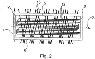
figure 2 est une vue de dessus d'une partie du dispositif illustré à lafigure 1 . - En référence aux différentes figures, le dispositif de chauffage par fermentation de biomasse selon le mode de réalisation particulier de l'invention, généralement désigné en 1, comprend un bac 2. Le bac 2 est ici agencé de sorte à s'étendre horizontalement relativement au sol sur lequel le bac 2 repose. Le bac 2 s'étend ainsi selon un axe X.
- Le bac 2 est ici de forme généralement parallélépipédique (de sorte qu'ici sa longueur s'étende selon l'axe X). Le bac 2 comporte un fond 3 et quatre parois s'étendant à partir du fond en direction du ciel dont deux parois longitudinales 5, 6 parallèles entre elles (qui s'étendent donc selon l'axe X) et deux parois latérales 7, 8 parallèles entre elles et perpendiculaires aux parois longitudinales (les parois latérales 7, 8 s'étendant donc selon un axe Y orthogonal à l'axe X).
- Les différentes parois comportent chacune des trous d'aération 9 (dont une partie seulement est référencée ici) qui favorisent la ventilation à l'intérieur du bac 2.
- Ces trous d'aération 9 sont ménagés à intervalles réguliers sur les différentes parois. Les différents trous d'aération 9 sont ici ménagés dans les parois de sorte à former des lignes parallèles les unes aux autres sur une même paroi et à un même niveau sur les quatre parois. Pour les parois longitudinales 5, 6, les différentes lignes s'étendent donc selon l'axe X et pour les parois latérales 7, 8, les différentes lignes s'étendent selon l'axe Y.
- De façon particulière, les parois du bac 2 sont construites à base de briques que l'on espace volontairement lors de la construction du bac 2 pour former naturellement lesdits trous d'aération 9. Les briques sont par exemple des Briques en Terre Comprimée (encore appelée BTC).
- Le dispositif 1 comporte ici un couvercle (non représenté ici), indépendant du bac 2, et conformé pour pouvoir venir reposer sur les quatre parois du bac 2 afin de fermer ledit bac 2.
- Le bac 2 comporte de façon particulière des pieds 10 pour pouvoir reposer sur le sol au niveau de ses pieds 10.
- De préférence, au moins une partie du fond du bac 2 est mobile relativement aux parois. Par exemple, une partie du fond du bac 2 est montée coulissante sur le reste du bac 2 selon un mouvement de translation d'axe X.
- Ceci permet de vider facilement le bac 2 par le bas.
- Le dispositif 1 comporte en outre ici des canalisations 12 agencées dans le bac 2 de sorte qu'une entrée et une sortie de chaque canalisation 12 s'étendent ici hors du bac 2. Mis à part par son entrée et sa sortie, chaque canalisation 12 s'étend entièrement à l'intérieur du bac 2. Chaque canalisation 12 est ici agencée de sorte que ses entrée et sortie s'étendent dans le prolongement du bac 2 selon l'axe X. Chaque canalisation 12 s'étend en outre ici dans le bac 2 de sorte qu'une entrée de la canalisation 12 pénètre dans le bac 2 plus bas que ne ressort la sortie de ladite canalisation 12.
- Le dispositif 1 comporte par exemple trois canalisations 12.
- Selon un mode de réalisation particulier, chaque canalisation 12 est identique. Chaque canalisation 12 est ici conformée en serpentin afin de favoriser les échanges d'un fluide circulant dans la canalisation 12 avec l'extérieur.
- De façon particulière, chaque canalisation 12 est plane mais agencée transversalement dans le bac 2 de sorte que l'entrée et la sortie de la canalisation 12 ne se retrouvent pas au même niveau (en terme de hauteur selon un axe Z orthogonal aux axes X et Y). En variante, le serpentin lui-même est conformé de sorte que l'entrée et la sortie de la canalisation 12 ne soient pas au même niveau (par exemple le serpentin forme un escalier entre l'entrée et la sortie de la canalisation 12).
- Les trois entrées des canalisations sont reliées en amont du bac 2 à un canal d'entrée 13 commun. Les trois sorties des canalisations 12 sont ici également reliées en aval du bac à un canal de sortie 14 commun.
- Par ailleurs, le dispositif 1 comporte des éléments de soutien des différentes canalisations 12. Les éléments de soutien traversent le bac 2 et dépassent du bac 2 et les canalisations 12 viennent simplement reposer sur ces éléments de soutien. De la sorte, le montage des canalisations 12 dans le bac 2 s'avère simple et rapide.
- Les éléments de soutien sont ici des tiges 15 (dont une partie seulement est référencée). Ces tiges 15 sont en matériau métallique par exemple en acier.
- Chaque tige 15 est agencée de sorte à s'étendre à travers le bac 2 et à dépasser à chacune de ses extrémités hors du bac 2 à travers des trous d'aération 9 des parois. De façon particulière, chaque tige 15 s'étend entre les deux parois longitudinales 5, 6.
- De préférence, chaque tige 15 s'étend transversalement à l'axe X dans le bac 2. Chaque tige 15 s'étend cependant ici dans un plan parallèle aux axes X et Y. Chaque tige 15 s'étend donc entre deux lignes de trous d'aération 9, lignes en regard l'une de l'autre sur les parois longitudinales 5, 6.
- De façon particulière, à chaque plan défini par deux lignes de trous d'aération 9 se faisant face sur les parois longitudinales 5, 6, différents tiges 15 sont agencées pour former un réseau de soutien des canalisations 12. De préférence, sur un même niveau, les tiges 15 sont agencées de sorte à former ensemble un zigzag s'étendant sur toute la surface du bac 2. De la sorte, deux extrémités de deux tiges 15 différentes (formant deux traits consécutifs du zigzag) ressortent du bac 2 par un même trou d'aération 9.
- De préférence, chaque tige 15 est agencée entre deux trous d'aération 9 sans toutefois être fixée au bac 2. De la sorte, chaque tige 15 peut aisément bouger relativement aux trous d'aération 9 entre lesquelles elle s'étend. Il s'avère en outre possible de retirer aisément chaque tige 15 ce qui est pratique pour pouvoir retirer et/ou agencer les canalisations 12 reposant sur lesdites tiges 15.
- De façon particulière, le dispositif 1 comporte également un réservoir 16 de stockage du fluide. Le réservoir 16 est agencé à proximité du bac 2. Le réservoir 16 est ici conformé en un cylindre reposant sur le sol. Le réservoir 16 est ici un ballon d'eau et le fluide circulant dans le dispositif 1 est donc de l'eau à chauffer.
- Le canal d'entrée 13 débouche dans le réservoir 16 au niveau de la partie basse du réservoir 16. Quant au canal de sortie 14, il débouche dans le réservoir 16 au niveau de la partie haute du réservoir 16. Le réservoir 16 comporte en outre au niveau de sa partie basse des moyens de vidange 17 du réservoir 16 pour extraire l'eau chaude dudit réservoir 16.
- Le dispositif 1 comporte par ailleurs une conduite 18 destinée à être reliée à une arrivée d'eau froide. Ladite conduite 18 est ici raccordée au canal d'entrée 13 par exemple à l'aide d'une vanne anti-retour 19 afin d'empêcher l'eau circulant dans le canal d'entrée 13 de pénétrer dans ladite conduite 18.
- Le dispositif 1 comporte en outre une pompe 20 associé au canal d'entrée 13 pour assurer la circulation de l'eau dans le dispositif 1.
- De préférence, le dispositif 1 comporte des moyens de contrôle du dispositif 1. Lesdits moyens comportent ici un contrôleur (non illustré ici) contrôlant la pompe 20 à l'aide de sondes de températures desdits moyens par exemple à l'aide d'une première sonde 21 mesurant la température dans le réservoir 16 et à l'aide d'une deuxième sonde 22 mesurant la température au niveau du canal de sortie 14.
- De préférence, les moyens de contrôle sont agencés de sorte à assurer que l'eau dans le réservoir 16 soit à la même température que l'eau circulant dans les canalisations 12.
- Une mise en place du dispositif 1 va être à présent décrite.
- Tout d'abord on retire le couvercle.
- On agence une couche de matière organique, comme par exemple de la paille, dans le fond du bac 2.
- Puis on vient déposer une couche de biomasse dans le fond du bac 2. De préférence, ladite biomasse est du fumier mais on pourra choisir toute autre matière développant de la chaleur lors de sa fermentation comme du compost ou d'autres déchets organiques.
- De façon avantageuse, les différentes tiges 15 peuvent être agitées autour des trous d'aérations 9 correspondants pour assurer que la biomasse tombe bien jusqu'au fond du dispositif 1 afin de bien entourer toutes les canalisations 12. Ceci permet également de tasser la biomasse et d'améliorer encore le recouvrement des canalisations 12. On note donc le rôle à la fois de soutien et d'aide à l'organisation de la biomasse dans le bac 2 des éléments de soutien.
- La couche inférieure de biomasse est par exemple d'environ 20 centimètres.
- Puis on vient agencer les canalisations 12 et achever de remplir le bac 2 de biomasse. Le bac 2 contient ainsi une succession de couches de biomasse et de canalisations. Le bac 2 contient en particulier une couche inférieure de biomasse recouvrant la paille de sorte que les canalisations 12 ne touchent pas la paille et une couche supérieure de biomasse recouvrant entièrement les canalisations 12 qui ne sont ainsi pas au contact de l'air libre.
- Les canalisations 12 sont donc enfouies dans la biomasse.
- De préférence, on vient ensuite recouvrir le haut de la biomasse d'une autre couche de matière organique comme par exemple de la paille. Ceci permet de bien isoler l'ensemble formé par la biomasse et les canalisations 12 de l'air extérieur.
- Puis on ferme le bac 2 avec le couvercle. De façon particulière, il demeure un espacement entre la couche de paille et le couvercle pour permettre une ventilation dans le bac 2. De préférence, une rangée de trous d'aération 9 de chaque paroi se trouve au niveau de cet espacement.
- Le dispositif 1 est alors prêt à fonctionner.
- Les moyens de contrôle ouvrent alors une vanne d'arrivée d'eau qui vient alors circuler dans les canalisations 12, le canal de sortie 14 avant d'arriver dans le réservoir 16. Les échanges thermiques au sein du bac 2 entre l'eau et la biomasse permettent de récupérer au niveau du canal de sortie 14 de l'eau chaude pour remplir le réservoir 16.
- Une fois le réservoir 16 rempli d'eau chaude les moyens de contrôle ferment la vanne d'arrivée d'eau et autorisent la circulation de l'eau dans le dispositif 1 selon une boucle (réservoir 16, canal d'entrée 13, canalisations 12, canal de sortie 14, réservoir 16) jusqu'à ce que l'eau dans le réservoir 16 atteigne la température visée. Les moyens de contrôle arrêtent alors la pompe 20 jusqu'à ce qu'il soit de nouveau nécessaire de réchauffer l'eau présente dans le réservoir 16 et donc de provoquer la circulation de l'eau dans le dispositif 1.
- Le dispositif 1 permet ainsi de chauffer rapidement et efficacement de l'eau alors même que le dispositif 1 est de structure très simple. Il est ainsi possible de chauffer de l'eau jusqu'à 60 ou 70 degrés Celsius voire même jusqu'à 75 degrés Celsius.
- Lorsqu'il s'avère nécessaire de changer la biomasse dans le bac 2 du fait que la fermentation n'est plus suffisante pour le chauffage visé, il suffit simplement de faire coulisser le fond du bac pour évacuer la biomasse par le bas du bac 2. De façon avantageuse, les éléments de soutien permettent encore une fois de faciliter l'évacuation de la biomasse par vibration desdits éléments de soutien.
- Il ne reste alors plus qu'à remettre le fond puis à remplir de nouveau le bac 2 comme décrit précédemment à l'aide de biomasse plus fraîche.
- De façon avantageuse, la biomasse évacuée peut encore être utilisée pour d'autres applications comme par exemple être utilisée comme fertilisant pour le domaine de l'agriculture.
- Le dispositif 1 ainsi décrit présente donc de nombreux avantages entre autres :
- le dispositif 1 permet de chauffer un fluide à l'aide d'une énergie propre,
- le chauffage du fluide peut se faire à proximité de l'endroit où le fluide est destiné à être utilisé,
- la biomasse utilisée est valorisée, de plus, dans le cas de fumier et/ou de compost, il est encore possible de valoriser ensuite le fumier et/ou le compost en l'utilisant comme engrais pour l'agriculture,
- le dispositif 1 est aisé à mettre en œuvre,
- le dispositif 1 est accessible à tous,
- le dispositif 1 est peu coûteux,
- le dispositif 1 n'émet pas ou peu de CO2 ce qui confirme son intérêt écologique.
- Le dispositif 1 peut en outre être utilisé pour de nombreuses applications. On peut ainsi utiliser le fluide chauffé par le dispositif 1 dans des domaines aussi diversifiés que les domaines domestique (habitat, bureau, lieu public ...), agricole ou industriel (aux fins de préchauffage par exemple).
- En ce qui concerne le domaine domestique, le fluide chauffé par le dispositif 1 peut être ainsi utilisé pour les besoins de la vie courante (douche, chauffage, serpentin, radiateur, air chaud ...). Dans le domaine agricole, le fluide chauffé par le dispositif 1 peut être ainsi utilisé par exemple pour chauffer des serres agricoles en vue d'une production optimale ou précoce de certains fruits et légumes. Il est aussi possible de chauffer les planchers des installations agricoles afin de contrer de fortes variations de températures entre la nuit et le jour. Dans le domaine industriel, le fluide chauffé peut permettre de faire des économies d'énergie notables. Les applications sont diverses et visent les utilisations à base d'eau chaude dans les processus de transformation alimentaire, la production séquentielle, le nettoyage de réservoirs, le préchauffage de l'eau d'appoint des chaudières, les aires de stockage, les magasins, les bâtiments industriels ...
- Bien entendu, l'invention n'est pas limitée au mode de réalisation décrit mais englobe toute variante entrant dans le cadre de l'invention telle que définie par les revendications.
- Par exemple, bien qu'ici le bac du dispositif soit agencé horizontalement, ledit bac pourra être agencé verticalement. Le bac pourra avoir une autre forme que celle décrite et par exemple une forme cylindrique.
- Le nombre de canalisations pourra être différent de ce qui a été indiqué. En outre, chaque canalisation pourra être conformée différemment et agencée différemment dans le bac. Ainsi bien qu'ici les canalisations s'étendent dans le bac de sorte que les entrées et sorties desdites canalisations s'étendent dans le prolongement du bac, la ou les canalisations pourront s'étendre différemment par rapport à la direction du bac. La ou les canalisations pourront être agencées de sorte qu'une entrée et une sortie d'une même canalisation se trouve à une même hauteur du bac.
- Le dispositif pourra ne pas comporter de couvercle. En variante, le bac lui-même pourra comporter un couvercle par exemple monté pivotant ou coulissant sur le reste du bac pour donner accès à l'intérieur du bac.
Les éléments de soutien pourront être différents de ce qui a été décrit et comporter par exemple des barres dont les deux extrémités sont prolongées par des poignées agencées hors du bac pour faciliter la manipulation des poignées.
Claims (10)
- Dispositif de chauffage par fermentation de biomasse, le dispositif comprenant un bac (2) ainsi qu'une canalisation (12) dans laquelle un fluide à chauffer est destiné à s'écouler, la canalisation étant agencée de sorte à circuler au moins en partie dans le bac pour, en service, être entourée par une biomasse agencée dans le bac, le dispositif comprenant des éléments de soutien (15) de la canalisation , caractérisé en ce que les éléments de soutien (15) de la canalisation traversent le bac et dépassent du bac.
- Dispositif selon la revendication 1, dans lequel le bac (2) s'étend horizontalement.
- Dispositif selon l'une des revendications précédentes, dans lequel le bac (2) est de forme généralement parallélépipédique.
- Dispositif selon l'une des revendications précédentes, dans lequel le bac (2) comporte des trous d'aération (9).
- Dispositif selon l'une des revendications précédentes, dans lequel au moins une partie du bac (2) est en briques.
- Dispositif selon la revendication 5, dans lequel les briques sont des Briques en Terre Comprimée.
- Dispositif selon l'une des revendications précédentes, dans lequel le bac (2) comporte des pieds (10) .
- Dispositif selon l'une des revendications précédentes, dans lequel au moins une partie d'un fond du bac (2) est mobile relativement au reste du bac.
- Dispositif selon l'une des revendications précédentes, dans lequel les éléments de soutien comportent des tiges (15).
- Dispositif selon la revendication 9, dans lequel les tiges (15) sont en matériau métallique.
Applications Claiming Priority (1)
| Application Number | Priority Date | Filing Date | Title |
|---|---|---|---|
| FR1659117A FR3056711B1 (fr) | 2016-09-27 | 2016-09-27 | Dispositif de chauffage par fermentation de biomasse |
Publications (2)
| Publication Number | Publication Date |
|---|---|
| EP3299745A1 EP3299745A1 (fr) | 2018-03-28 |
| EP3299745B1 true EP3299745B1 (fr) | 2020-10-07 |
Family
ID=57485723
Family Applications (1)
| Application Number | Title | Priority Date | Filing Date |
|---|---|---|---|
| EP17186551.2A Not-in-force EP3299745B1 (fr) | 2016-09-27 | 2017-08-17 | Dispositif de chauffage par fermentation de biomasse |
Country Status (3)
| Country | Link |
|---|---|
| EP (1) | EP3299745B1 (fr) |
| FR (1) | FR3056711B1 (fr) |
| MA (1) | MA41707B1 (fr) |
Family Cites Families (8)
| Publication number | Priority date | Publication date | Assignee | Title |
|---|---|---|---|---|
| AT338839B (de) * | 1974-05-20 | 1977-09-12 | Posostron Ag | Komposter fur hausmull und gartenabfalle |
| DE8215688U1 (de) * | 1982-05-28 | 1982-08-12 | Handlbauer, Engelbert, 4240 Freistadt | Vorrichtung zur gewinnung von waermeenergie aus festmist |
| DE3905158A1 (de) * | 1989-02-20 | 1990-08-30 | Wilkens Bremer Silberwaren Ag | Baukastensystem fuer bioreaktoren |
| US6508409B1 (en) * | 2001-09-24 | 2003-01-21 | Robert Grantz | Heat producing system for a building |
| DE202006001119U1 (de) * | 2005-08-25 | 2006-06-29 | Wolff, Rando, Dipl.-Betriebsw. | Containertrockenanlage für Bio-Materialien |
| WO2012045166A1 (fr) * | 2010-10-07 | 2012-04-12 | Alfi Cardinale | Chauffage de piscines à l'aide d'échangeurs de chaleur par réalisation de cycle d'eau de piscine à travers un élément chauffant du type à compost |
| DE202013000887U1 (de) * | 2013-01-29 | 2013-02-28 | Dirk Wasse | Eine Vorrichtung zur Wiederbefüllung von Substraten aller Arten und zur Steuerung des Verrottungsprozesses zur Erzeugung von Biowärme durch Verrottung |
| WO2016061701A1 (fr) * | 2014-10-24 | 2016-04-28 | Média K-Plus Inc./K-Plus Media Inc. | Chauffe-eau à compostage et procédé de chauffage d'eau par du compost |
-
2016
- 2016-09-27 FR FR1659117A patent/FR3056711B1/fr not_active Expired - Fee Related
-
2017
- 2017-08-17 EP EP17186551.2A patent/EP3299745B1/fr not_active Not-in-force
- 2017-08-17 MA MA41707A patent/MA41707B1/fr unknown
Non-Patent Citations (1)
| Title |
|---|
| None * |
Also Published As
| Publication number | Publication date |
|---|---|
| FR3056711A1 (fr) | 2018-03-30 |
| MA41707A (fr) | 2018-03-28 |
| MA41707B1 (fr) | 2021-01-29 |
| EP3299745A1 (fr) | 2018-03-28 |
| FR3056711B1 (fr) | 2018-10-26 |
Similar Documents
| Publication | Publication Date | Title |
|---|---|---|
| CA2659554C (fr) | Bac de retention d'eau | |
| EP2847535A1 (fr) | Réservoir de stockage de chaleur a stratification thermique améliorée | |
| EP3194670B1 (fr) | Dispositif de toilettes | |
| EP2775245B1 (fr) | Dispositif de stockage d'énergie thermique | |
| EP3024333B1 (fr) | Dispositif de distribution de levure en boulangerie et système de distribution de levure en boulangerie | |
| FR2947560A1 (fr) | Reacteur pour la methanisation de la biomasse | |
| EP3299745A1 (fr) | Dispositif de chauffage par fermentation de biomasse | |
| EP2117995B1 (fr) | Installation souterraine de stockage d'huile alimentaire | |
| EP2684848B1 (fr) | Installation de lavage et de recyclage d'eau chargee de gravats | |
| FR2912875A1 (fr) | "dispositif de desherbage thermique" | |
| FR2923812A1 (fr) | Dispositif transportable de stockage et de distribution d'hydrocarbures. | |
| EP3423772B1 (fr) | Reservoir de stockage de chaleur a fonctionnement optimise | |
| FR3071045A1 (fr) | Systeme souterrain de stockage de chaleur pour installation de production de chauffage et/ou d'eau chaude sanitaire | |
| EP3426763B1 (fr) | Cuvier et bâtiment comprenant un tel cuvier | |
| FR3016823A1 (fr) | Centrale de fabrication d'un materiau de construction | |
| EP2117996B1 (fr) | Dispositif de chauffage d'un conteneur de stockage de recuperation d'huile alimentaire | |
| FR3162776A1 (fr) | Terrasse mobile pour bassin, équipée pour contrôler des caractéristiques de l’eau du bassin | |
| EP4481138A1 (fr) | Ensemble comprenant un bassin et permettant un stockage hydrique | |
| FR2786853A1 (fr) | Dispositif de production d'eau chaude sanitaire | |
| WO2015092331A1 (fr) | Procédé d'injection de fluides dans une installation sous-marine | |
| EP2474674A1 (fr) | Dispositif de siphon à amorçage automatique | |
| FR2969260A1 (fr) | Systeme de production d'eau chaude sanitaire a l'aide de capteurs solaires thermiques a eau, dans lequel un meme circuit met en relation un ballon d'eau chaude et les capteurs. | |
| FR2488907A1 (fr) | Procede et dispositif pour la production en continu de gaz utiles a partir de matieres organiques | |
| FR2630783A1 (fr) | Systeme hydraulique de refoulement de liquide en hauteur par utilisation de la poussee hydrostatique, dit exhausseur | |
| FR3091968A1 (fr) | Dispositif de stockage pour produits destinés à être immergés, son utilisation et ensemble de stockage correspondant |
Legal Events
| Date | Code | Title | Description |
|---|---|---|---|
| PUAI | Public reference made under article 153(3) epc to a published international application that has entered the european phase |
Free format text: ORIGINAL CODE: 0009012 |
|
| STAA | Information on the status of an ep patent application or granted ep patent |
Free format text: STATUS: THE APPLICATION HAS BEEN PUBLISHED |
|
| AK | Designated contracting states |
Kind code of ref document: A1 Designated state(s): AL AT BE BG CH CY CZ DE DK EE ES FI FR GB GR HR HU IE IS IT LI LT LU LV MC MK MT NL NO PL PT RO RS SE SI SK SM TR |
|
| AX | Request for extension of the european patent |
Extension state: BA ME |
|
| STAA | Information on the status of an ep patent application or granted ep patent |
Free format text: STATUS: REQUEST FOR EXAMINATION WAS MADE |
|
| 17P | Request for examination filed |
Effective date: 20180926 |
|
| RAV | Requested validation state of the european patent: fee paid |
Extension state: MD Effective date: 20180926 Extension state: MA Effective date: 20170817 |
|
| RBV | Designated contracting states (corrected) |
Designated state(s): AL AT BE BG CH CY CZ DE DK EE ES FI FR GB GR HR HU IE IS IT LI LT LU LV MC MK MT NL NO PL PT RO RS SE SI SK SM TR |
|
| RIC1 | Information provided on ipc code assigned before grant |
Ipc: F24V 99/00 20180101AFI20200302BHEP |
|
| GRAP | Despatch of communication of intention to grant a patent |
Free format text: ORIGINAL CODE: EPIDOSNIGR1 |
|
| STAA | Information on the status of an ep patent application or granted ep patent |
Free format text: STATUS: GRANT OF PATENT IS INTENDED |
|
| INTG | Intention to grant announced |
Effective date: 20200504 |
|
| GRAS | Grant fee paid |
Free format text: ORIGINAL CODE: EPIDOSNIGR3 |
|
| GRAA | (expected) grant |
Free format text: ORIGINAL CODE: 0009210 |
|
| STAA | Information on the status of an ep patent application or granted ep patent |
Free format text: STATUS: THE PATENT HAS BEEN GRANTED |
|
| AK | Designated contracting states |
Kind code of ref document: B1 Designated state(s): AL AT BE BG CH CY CZ DE DK EE ES FI FR GB GR HR HU IE IS IT LI LT LU LV MC MK MT NL NO PL PT RO RS SE SI SK SM TR |
|
| REG | Reference to a national code |
Ref country code: GB Ref legal event code: FG4D Free format text: NOT ENGLISH |
|
| REG | Reference to a national code |
Ref country code: CH Ref legal event code: EP Ref country code: AT Ref legal event code: REF Ref document number: 1321564 Country of ref document: AT Kind code of ref document: T Effective date: 20201015 |
|
| REG | Reference to a national code |
Ref country code: IE Ref legal event code: FG4D Free format text: LANGUAGE OF EP DOCUMENT: FRENCH |
|
| REG | Reference to a national code |
Ref country code: DE Ref legal event code: R096 Ref document number: 602017024909 Country of ref document: DE |
|
| REG | Reference to a national code |
Ref country code: MA Ref legal event code: VAGR Ref document number: 41707 Country of ref document: MA Kind code of ref document: B1 |
|
| REG | Reference to a national code |
Ref country code: NL Ref legal event code: MP Effective date: 20201007 |
|
| REG | Reference to a national code |
Ref country code: AT Ref legal event code: MK05 Ref document number: 1321564 Country of ref document: AT Kind code of ref document: T Effective date: 20201007 |
|
| PG25 | Lapsed in a contracting state [announced via postgrant information from national office to epo] |
Ref country code: RS Free format text: LAPSE BECAUSE OF FAILURE TO SUBMIT A TRANSLATION OF THE DESCRIPTION OR TO PAY THE FEE WITHIN THE PRESCRIBED TIME-LIMIT Effective date: 20201007 Ref country code: PT Free format text: LAPSE BECAUSE OF FAILURE TO SUBMIT A TRANSLATION OF THE DESCRIPTION OR TO PAY THE FEE WITHIN THE PRESCRIBED TIME-LIMIT Effective date: 20210208 Ref country code: NL Free format text: LAPSE BECAUSE OF FAILURE TO SUBMIT A TRANSLATION OF THE DESCRIPTION OR TO PAY THE FEE WITHIN THE PRESCRIBED TIME-LIMIT Effective date: 20201007 Ref country code: NO Free format text: LAPSE BECAUSE OF FAILURE TO SUBMIT A TRANSLATION OF THE DESCRIPTION OR TO PAY THE FEE WITHIN THE PRESCRIBED TIME-LIMIT Effective date: 20210107 Ref country code: FI Free format text: LAPSE BECAUSE OF FAILURE TO SUBMIT A TRANSLATION OF THE DESCRIPTION OR TO PAY THE FEE WITHIN THE PRESCRIBED TIME-LIMIT Effective date: 20201007 Ref country code: GR Free format text: LAPSE BECAUSE OF FAILURE TO SUBMIT A TRANSLATION OF THE DESCRIPTION OR TO PAY THE FEE WITHIN THE PRESCRIBED TIME-LIMIT Effective date: 20210108 |
|
| REG | Reference to a national code |
Ref country code: LT Ref legal event code: MG4D |
|
| PG25 | Lapsed in a contracting state [announced via postgrant information from national office to epo] |
Ref country code: ES Free format text: LAPSE BECAUSE OF FAILURE TO SUBMIT A TRANSLATION OF THE DESCRIPTION OR TO PAY THE FEE WITHIN THE PRESCRIBED TIME-LIMIT Effective date: 20201007 Ref country code: AT Free format text: LAPSE BECAUSE OF FAILURE TO SUBMIT A TRANSLATION OF THE DESCRIPTION OR TO PAY THE FEE WITHIN THE PRESCRIBED TIME-LIMIT Effective date: 20201007 Ref country code: BG Free format text: LAPSE BECAUSE OF FAILURE TO SUBMIT A TRANSLATION OF THE DESCRIPTION OR TO PAY THE FEE WITHIN THE PRESCRIBED TIME-LIMIT Effective date: 20210107 Ref country code: IS Free format text: LAPSE BECAUSE OF FAILURE TO SUBMIT A TRANSLATION OF THE DESCRIPTION OR TO PAY THE FEE WITHIN THE PRESCRIBED TIME-LIMIT Effective date: 20210207 Ref country code: LV Free format text: LAPSE BECAUSE OF FAILURE TO SUBMIT A TRANSLATION OF THE DESCRIPTION OR TO PAY THE FEE WITHIN THE PRESCRIBED TIME-LIMIT Effective date: 20201007 Ref country code: PL Free format text: LAPSE BECAUSE OF FAILURE TO SUBMIT A TRANSLATION OF THE DESCRIPTION OR TO PAY THE FEE WITHIN THE PRESCRIBED TIME-LIMIT Effective date: 20201007 Ref country code: SE Free format text: LAPSE BECAUSE OF FAILURE TO SUBMIT A TRANSLATION OF THE DESCRIPTION OR TO PAY THE FEE WITHIN THE PRESCRIBED TIME-LIMIT Effective date: 20201007 |
|
| PG25 | Lapsed in a contracting state [announced via postgrant information from national office to epo] |
Ref country code: HR Free format text: LAPSE BECAUSE OF FAILURE TO SUBMIT A TRANSLATION OF THE DESCRIPTION OR TO PAY THE FEE WITHIN THE PRESCRIBED TIME-LIMIT Effective date: 20201007 |
|
| REG | Reference to a national code |
Ref country code: DE Ref legal event code: R097 Ref document number: 602017024909 Country of ref document: DE |
|
| PG25 | Lapsed in a contracting state [announced via postgrant information from national office to epo] |
Ref country code: LT Free format text: LAPSE BECAUSE OF FAILURE TO SUBMIT A TRANSLATION OF THE DESCRIPTION OR TO PAY THE FEE WITHIN THE PRESCRIBED TIME-LIMIT Effective date: 20201007 Ref country code: SM Free format text: LAPSE BECAUSE OF FAILURE TO SUBMIT A TRANSLATION OF THE DESCRIPTION OR TO PAY THE FEE WITHIN THE PRESCRIBED TIME-LIMIT Effective date: 20201007 Ref country code: CZ Free format text: LAPSE BECAUSE OF FAILURE TO SUBMIT A TRANSLATION OF THE DESCRIPTION OR TO PAY THE FEE WITHIN THE PRESCRIBED TIME-LIMIT Effective date: 20201007 Ref country code: EE Free format text: LAPSE BECAUSE OF FAILURE TO SUBMIT A TRANSLATION OF THE DESCRIPTION OR TO PAY THE FEE WITHIN THE PRESCRIBED TIME-LIMIT Effective date: 20201007 Ref country code: SK Free format text: LAPSE BECAUSE OF FAILURE TO SUBMIT A TRANSLATION OF THE DESCRIPTION OR TO PAY THE FEE WITHIN THE PRESCRIBED TIME-LIMIT Effective date: 20201007 Ref country code: RO Free format text: LAPSE BECAUSE OF FAILURE TO SUBMIT A TRANSLATION OF THE DESCRIPTION OR TO PAY THE FEE WITHIN THE PRESCRIBED TIME-LIMIT Effective date: 20201007 |
|
| PLBE | No opposition filed within time limit |
Free format text: ORIGINAL CODE: 0009261 |
|
| STAA | Information on the status of an ep patent application or granted ep patent |
Free format text: STATUS: NO OPPOSITION FILED WITHIN TIME LIMIT |
|
| PG25 | Lapsed in a contracting state [announced via postgrant information from national office to epo] |
Ref country code: DK Free format text: LAPSE BECAUSE OF FAILURE TO SUBMIT A TRANSLATION OF THE DESCRIPTION OR TO PAY THE FEE WITHIN THE PRESCRIBED TIME-LIMIT Effective date: 20201007 |
|
| VS25 | Lapsed in a validation state [announced via postgrant information from nat. office to epo] |
Ref country code: MD Free format text: LAPSE BECAUSE OF FAILURE TO SUBMIT A TRANSLATION OF THE DESCRIPTION OR TO PAY THE FEE WITHIN THE PRESCRIBED TIME-LIMIT Effective date: 20201007 |
|
| 26N | No opposition filed |
Effective date: 20210708 |
|
| PG25 | Lapsed in a contracting state [announced via postgrant information from national office to epo] |
Ref country code: AL Free format text: LAPSE BECAUSE OF FAILURE TO SUBMIT A TRANSLATION OF THE DESCRIPTION OR TO PAY THE FEE WITHIN THE PRESCRIBED TIME-LIMIT Effective date: 20201007 Ref country code: IT Free format text: LAPSE BECAUSE OF FAILURE TO SUBMIT A TRANSLATION OF THE DESCRIPTION OR TO PAY THE FEE WITHIN THE PRESCRIBED TIME-LIMIT Effective date: 20201007 |
|
| PG25 | Lapsed in a contracting state [announced via postgrant information from national office to epo] |
Ref country code: SI Free format text: LAPSE BECAUSE OF FAILURE TO SUBMIT A TRANSLATION OF THE DESCRIPTION OR TO PAY THE FEE WITHIN THE PRESCRIBED TIME-LIMIT Effective date: 20201007 |
|
| REG | Reference to a national code |
Ref country code: DE Ref legal event code: R119 Ref document number: 602017024909 Country of ref document: DE |
|
| REG | Reference to a national code |
Ref country code: CH Ref legal event code: PL |
|
| PG25 | Lapsed in a contracting state [announced via postgrant information from national office to epo] |
Ref country code: MC Free format text: LAPSE BECAUSE OF FAILURE TO SUBMIT A TRANSLATION OF THE DESCRIPTION OR TO PAY THE FEE WITHIN THE PRESCRIBED TIME-LIMIT Effective date: 20201007 |
|
| REG | Reference to a national code |
Ref country code: BE Ref legal event code: MM Effective date: 20210831 |
|
| GBPC | Gb: european patent ceased through non-payment of renewal fee |
Effective date: 20210817 |
|
| PG25 | Lapsed in a contracting state [announced via postgrant information from national office to epo] |
Ref country code: LI Free format text: LAPSE BECAUSE OF NON-PAYMENT OF DUE FEES Effective date: 20210831 Ref country code: CH Free format text: LAPSE BECAUSE OF NON-PAYMENT OF DUE FEES Effective date: 20210831 |
|
| PG25 | Lapsed in a contracting state [announced via postgrant information from national office to epo] |
Ref country code: IS Free format text: LAPSE BECAUSE OF FAILURE TO SUBMIT A TRANSLATION OF THE DESCRIPTION OR TO PAY THE FEE WITHIN THE PRESCRIBED TIME-LIMIT Effective date: 20210207 Ref country code: LU Free format text: LAPSE BECAUSE OF NON-PAYMENT OF DUE FEES Effective date: 20210817 |
|
| PG25 | Lapsed in a contracting state [announced via postgrant information from national office to epo] |
Ref country code: IE Free format text: LAPSE BECAUSE OF NON-PAYMENT OF DUE FEES Effective date: 20210817 Ref country code: GB Free format text: LAPSE BECAUSE OF NON-PAYMENT OF DUE FEES Effective date: 20210817 Ref country code: DE Free format text: LAPSE BECAUSE OF NON-PAYMENT OF DUE FEES Effective date: 20220301 Ref country code: BE Free format text: LAPSE BECAUSE OF NON-PAYMENT OF DUE FEES Effective date: 20210831 |
|
| PG25 | Lapsed in a contracting state [announced via postgrant information from national office to epo] |
Ref country code: HU Free format text: LAPSE BECAUSE OF FAILURE TO SUBMIT A TRANSLATION OF THE DESCRIPTION OR TO PAY THE FEE WITHIN THE PRESCRIBED TIME-LIMIT; INVALID AB INITIO Effective date: 20170817 |
|
| PG25 | Lapsed in a contracting state [announced via postgrant information from national office to epo] |
Ref country code: CY Free format text: LAPSE BECAUSE OF FAILURE TO SUBMIT A TRANSLATION OF THE DESCRIPTION OR TO PAY THE FEE WITHIN THE PRESCRIBED TIME-LIMIT Effective date: 20201007 |
|
| PG25 | Lapsed in a contracting state [announced via postgrant information from national office to epo] |
Ref country code: MK Free format text: LAPSE BECAUSE OF FAILURE TO SUBMIT A TRANSLATION OF THE DESCRIPTION OR TO PAY THE FEE WITHIN THE PRESCRIBED TIME-LIMIT Effective date: 20201007 |
|
| PG25 | Lapsed in a contracting state [announced via postgrant information from national office to epo] |
Ref country code: MT Free format text: LAPSE BECAUSE OF FAILURE TO SUBMIT A TRANSLATION OF THE DESCRIPTION OR TO PAY THE FEE WITHIN THE PRESCRIBED TIME-LIMIT Effective date: 20201007 |
|
| PGFP | Annual fee paid to national office [announced via postgrant information from national office to epo] |
Ref country code: FR Payment date: 20240829 Year of fee payment: 8 |
|
| VSFP | Annual fee paid to validation state [announced via postgrant information from national office to epo] |
Ref country code: MA Payment date: 20230810 Year of fee payment: 7 |
|
| VSFP | Annual fee paid to validation state [announced via postgrant information from national office to epo] |
Ref country code: MA Payment date: 20220804 Year of fee payment: 6 Ref country code: MA Payment date: 20210806 Year of fee payment: 5 |
|
| VSFP | Annual fee paid to validation state [announced via postgrant information from national office to epo] |
Ref country code: MA Payment date: 20240830 Year of fee payment: 8 |
|
| PG25 | Lapsed in a contracting state [announced via postgrant information from national office to epo] |
Ref country code: TR Free format text: LAPSE BECAUSE OF FAILURE TO SUBMIT A TRANSLATION OF THE DESCRIPTION OR TO PAY THE FEE WITHIN THE PRESCRIBED TIME-LIMIT Effective date: 20201007 |
|
| VS25 | Lapsed in a validation state [announced via postgrant information from nat. office to epo] |
Ref country code: MA Free format text: LAPSE BECAUSE OF NON-PAYMENT OF DUE FEES Effective date: 20250818 |
|
| PG25 | Lapsed in a contracting state [announced via postgrant information from national office to epo] |
Ref country code: FR Free format text: LAPSE BECAUSE OF NON-PAYMENT OF DUE FEES Effective date: 20250831 |