EP3299252A1 - Steering wheel decorative member - Google Patents
Steering wheel decorative member Download PDFInfo
- Publication number
- EP3299252A1 EP3299252A1 EP17192825.2A EP17192825A EP3299252A1 EP 3299252 A1 EP3299252 A1 EP 3299252A1 EP 17192825 A EP17192825 A EP 17192825A EP 3299252 A1 EP3299252 A1 EP 3299252A1
- Authority
- EP
- European Patent Office
- Prior art keywords
- decorative member
- steering wheel
- adhesion region
- stress
- decorative
- Prior art date
- Legal status (The legal status is an assumption and is not a legal conclusion. Google has not performed a legal analysis and makes no representation as to the accuracy of the status listed.)
- Granted
Links
Images



Classifications
-
- B—PERFORMING OPERATIONS; TRANSPORTING
- B62—LAND VEHICLES FOR TRAVELLING OTHERWISE THAN ON RAILS
- B62D—MOTOR VEHICLES; TRAILERS
- B62D1/00—Steering controls, i.e. means for initiating a change of direction of the vehicle
- B62D1/02—Steering controls, i.e. means for initiating a change of direction of the vehicle vehicle-mounted
- B62D1/04—Hand wheels
- B62D1/06—Rims, e.g. with heating means; Rim covers
Definitions
- a fixing member for sliced veneer is fixed to a metal core with screws and the sliced veneer is attached to the front surface of the fixing member for sliced veneer with an adhesive.
- a decorative member according to the invention configured to be mounted on a resin member covering a periphery of a ring core of a steering wheel is provided.
- an adhesion region in which the decorative member is adhered to the resin member is provided so that a width of the adhesion region is reduced from a central portion on a back surface facing the resin member toward circumferential end portions.
- the strength of the decorative member 20 depends on the material and/or thickness of the decorative member 20. On the other hand, it is effective that an adhesion region (area) of the adhesive 11 is properly determined in order to make a stress exerted on the portion adhered with the adhesive 11 less likely to concentrate on one site of the decorative member 20 when a load acts on the steering wheel 1.
- a fixing part such as an elastic clip (not illustrated) for fixing the decorative member 20 to the ring portion 6 and/or a backing material (not illustrated) can be provided in the non-adhesion region 13, for example.
- the wood members of Comparative Examples 1 to 3 include a wood member having a back surface entirely applied with an adhesive, a wood member having various external shapes and adhesion regions, or a wood member having a non-adhered portion formed linearly in the circumferential direction.
- the wood members of Comparative Examples 4 to 7 include a wood member, some portion of which is formed thinner.
- the wood members of Comparative Examples 8 to 11 include a wood member, some portion of which extending in the circumferential direction is formed thinner regardless of an adhered portion with the cover portion 9.
- the wood member of Comparative Example 12 is a backed wood member.
- FIG. 3 clearly shows that an increase rate of the stress that acts on each of the wood members constituting the decorative members of Comparative Examples 1 to 12 is increased along with an increase in the ovalization-amount compared with increase rates of Examples 1, 2.
- an area (maximum stress area) P on which the maximum stress acts in the cross-sectional direction of the decorative member 20 extends in the circumferential direction of the decorative member 20.
- a decorative member 20 having the adhesion region 12 that is gradually reduced in width from the central portion 21 on the back surface facing the cover portion 9 toward the circumferential end portions 22, can be used.
- Such a decorative member 20 has an impact resistance that does not practically cause a trouble.
- the adhesion region 12 is provided so that a stress that acts on the portion adhered with the adhesive 11 is less likely to concentrate on one site of the decorative member 20, which causes the stress that acts on the decorative member 20 to be dispersed and reduced even when the stress has acted on the portion adhered with the adhesive 11. Accordingly, a separation at an interface between the decorative member 20 and the cover portion 9 can be less likely to occur.
Landscapes
- Engineering & Computer Science (AREA)
- Chemical & Material Sciences (AREA)
- Combustion & Propulsion (AREA)
- Transportation (AREA)
- Mechanical Engineering (AREA)
- Steering Controls (AREA)
Abstract
Description
- The present invention relates to a steering wheel decorative member that enhances the aesthetics of the front surface of a steering wheel, and particularly relates to a steering wheel decorative member that attaches to a ring portion of a steering wheel.
- As an example of a steering wheel having an enhanced outward appearance, a steering wheel in which a sliced veneer is attached to a ring portion is disclosed (refer to
JP 2000-142424A - In the steering wheel described in the above-described
JP 2000-142424A - According to the above-described
JP 2000-142424A - As described above, the steering wheel disclosed in the above-described
JP 2000-142424A - Accordingly, an object of the invention is to provide a steering wheel decorative member capable of dispersing and reducing the stress concentratedly exerted on the steering wheel decorative member when a load acts on the steering wheel.
- To achieve the above-described object, a decorative member according to the invention, configured to be mounted on a resin member covering a periphery of a ring core of a steering wheel is provided. In such a decorative member, an adhesion region in which the decorative member is adhered to the resin member is provided so that a width of the adhesion region is reduced from a central portion on a back surface facing the resin member toward circumferential end portions.
- In the steering wheel decorative member according to the invention, it is preferable that the adhesion region be provided on an upper end side on an occupant-facing surface of the decorative member.
- Furthermore, in the steering wheel decorative member according to the invention, the decorative member may be formed of a wood material.
- According to the invention, when a load acts on the steering wheel, a stress concentratedly exerted on the decorative member can be dispersed and reduced.
-
-
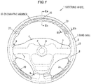
FIG. 1 is a schematic plan view illustrating an example of a steering wheel provided with a decorative member according to a preferred embodiment of the invention. -
FIG. 2A is a schematic view of the back surface of the decorative member, illustrating an example of an adhesion region of the decorative member according to the embodiment. -
FIG. 2B is an enlarged view of a cross-section of a main part taken along line IIa-IIa inFIG. 1 , illustrating an example of the adhesion region of the decorative member according to the embodiment. -
FIG. 2C is an enlarged view of a cross-section of a main part taken along lines IIb-IIb inFIG. 1 , illustrating an example of the adhesion region of the decorative member according to the embodiment. -
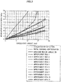
FIG. 3 is a diagram showing the relation between an ovalization-amount of a wood member constituting the decorative member and a stress. -
FIG. 4A is a partial schematic perspective view of the decorative member according to the embodiment, illustrating an example of a stress distribution in the decorative member. -
FIG. 4B is a partial schematic front view of the decorative member according to the embodiment, illustrating an example of the stress distribution in the decorative member. -
FIG. 4C is a partial schematic side view of the decorative member according to the embodiment, illustrating an example of the stress distribution in the decorative member. -
FIG. 4D is a partial schematic rear view of the decorative member according to the embodiment, illustrating an example of the stress distribution in the decorative member. -
FIG. 5 is a partial schematic perspective view corresponding toFIG. 4A , illustrating an example of an adhesion region of a decorative member according to a modified example. -
FIG. 6A is a partial schematic front view of a decorative member according a comparative example, illustrating an example of a stress distribution in the decorative member. -
FIG. 6B is a partial schematic side view of the decorative member according to the comparative example, illustrating an example of the stress distribution in the decorative member. - Preferred embodiments of the invention will be described in detail hereinafter with reference to the appended drawings.
- In
FIG. 1 , areference sign 1 indicating an overall configuration schematically indicates an automotive steering wheel provided with a typicaldecorative member 20 according to the present embodiment. Note that, in the description below, a front surface of thesteering wheel 1 will also be referred to as a front portion, a back surface of thesteering wheel 1 will also be referred to as a rear portion, and directions as viewed from the front surface of thesteering wheel 1 are referred to as up, down, left, and right. - The
steering wheel 1 according to an example illustrated in the drawings includes acylindrical boss portion 3 fitted and fixed to the leading end of asteering shaft 2, apad portion 4 attached to an upper portion of theboss portion 3, aring portion 6 that covers aring core 5, and spokeportions 8 that partially cover threespoke cores 7 that connect thering core 5 of thering portion 6 with theboss portion 3. - As illustrated in
FIGS. 1 ,2B, and 2C , acover portion 9 made from a resin member such as polyurethane covers an outer circumferential portion of thering portion 6 and an outer circumferential portion of thespoke portion 8. Attached to the surface of thecover portion 9 are askin portion 10 made of leather, and thedecorative member 20 having a design surface intended to improve an outward appearance design of thesteering wheel 1. - The
decorative member 20 illustrated in the drawings is composed of three members including adecorative member 20 provided on the top side, adecorative member 20 provided on the lower left side, and adecorative member 20 provided on the lower right side of thering portion 6 that is a grip part to be gripped by a driver. - Next, a description is given of the
decorative member 20. Note that thedecorative members 20 provided on the lower left side and lower right side of thering portion 6 have the same shape and structure as thedecorative member 20 provided on top side of thering portion 6. Accordingly, detailed descriptions of thedecorative members 20 provided on the lower left side and lower right side are omitted. - As illustrated in
FIG. 1 ,FIG. 2A, FIG. 2B, and FIG. 2C , thedecorative member 20 constituting a design portion is formed of a wood material and a cross section of thedecorative member 20 is a substantially semi-oval shape. Thedecorative member 20 is bent along the circumferential direction of thering portion 6 and covers a substantially quadrant portion on the occupant-facing surface of thering portion 6. The back surface of thedecorative member 20 is fixed to thecover portion 9 with an adhesive 11. - Examples of the wood material include a walnut material, a maple material, a bamboo material, and the like. A material of the
decorative member 20 is not limited to the wood material, and, for example, various types of resin materials can be used. From the perspective of enhancing the outward appearance design, the front surface of a resin material is preferably decorated with a wood grain pattern or the like. An epoxy-based adhesive or the like can be used as theadhesive 11, for example. - The
decorative member 20 is bonded to thecover portion 9, formed of the resin member such as polyurethane, along the circumferential direction of thecover portion 9 with theadhesive 11. Thus, when a load acts on thesteering wheel 1 thus configured, a stress is exerted on a portion of thedecorative member 20 adhered withadhesive 11 in response to a deformation of thering core 5 covered by thecover portion 9. When the stress concentratedly acts on one site of thedecorative member 20, fractures, cracks, or the like can possibly develop in thedecorative member 20. - The strength of the
decorative member 20 depends on the material and/or thickness of thedecorative member 20. On the other hand, it is effective that an adhesion region (area) of the adhesive 11 is properly determined in order to make a stress exerted on the portion adhered with the adhesive 11 less likely to concentrate on one site of thedecorative member 20 when a load acts on thesteering wheel 1. - It is preferable that an
adhesion region 12, in which the back surface of thedecorative member 20 is adhered and fixed to thecover portion 9, be provided so that the width of theadhesion region 12 is gradually reduced from acentral portion 21 on the back surface, facing thecover portion 9, of thedecorative member 20 toward bothcircumferential end portions 22 on the left and right sides in the circumferential direction. - In the illustrated example, the
adhesion region 12 is provided so that the width thereof is gradually reduced from thecentral portion 21 on the back surface of thedecorative member 20 toward both thecircumferential end portions 22 on the left and right sides in the circumferential direction, which makes an adhesion width W2 at thecircumferential end portions 22 narrower than an adhesion width W1 at thecentral portion 21. It is more preferable that theadhesion region 12 be provided on anupper end portion 23 side on an occupant-facing surface of thedecorative member 20, which enables the stress that acts on thedecorative member 20 to be reduced and the maximum stress to be dispersed. - A
non-adhesion region 13, in which the back surface of thedecorative member 20 is not adhered and fixed to thecover portion 9, is provided at an area other than theadhesion region 12 provided on the back surface of thedecorative member 20. It is preferable that thenon-adhesion region 13 be provided so that the width thereof is gradually increased from thecentral portion 21 on the back surface of thedecorative member 20 toward both thecircumferential end portions 22 on the left and right sides in the circumferential direction. A fixing part such as an elastic clip (not illustrated) for fixing thedecorative member 20 to thering portion 6 and/or a backing material (not illustrated) can be provided in thenon-adhesion region 13, for example. - Description of further detailed examples of the invention will be given below together with comparative examples.
-
FIG. 3 shows the relation between ovalization-amounts (mm) of wood members and a wood-developed-stress (MPa) which develops in the wood members. The wood members are formed in accordance withimprovement proposals 10, 11 (hereinafter, referred to as Examples 1, 2 in this order), an evaluation specification, an initial designed configuration, an adhesion region variation, andimprovement proposals 1 to 9 (hereinafter, referred to as Comparative Examples 1 to 12 in this order). The wood members of Examples 1, 2 and Comparative Examples 1 to 12 have various shapes and adhesion regions and are each adhered and fixed to thecover portion 9 of thesteering wheel 1. - In
FIG. 3 , the horizontal axis corresponds to the history of an ellipse-amount (ovalization-amount), which indicates the degree of ovalization of a wood member while the vertical axis corresponds to the history of a stress that acts on a wood member relative to a variation in the ovalization-amount. The ovalization-amount indicates a difference (mm) between a major axis and a minor axis of an oval cross-section of a wood member. - The respective wood members of Examples 1, 2 are provided with two different adhesion areas, to which an adhesive is applied. As illustrated in
FIG. 4A andFIG. 5 , such adhesion areas are gradually reduced in the circumferential direction from the central portion of an upper half of the wood member in a direction along the major axis of the ellipse. - On the other hand, the wood members of Comparative Examples 1 to 3 include a wood member having a back surface entirely applied with an adhesive, a wood member having various external shapes and adhesion regions, or a wood member having a non-adhered portion formed linearly in the circumferential direction.
- The wood members of Comparative Examples 4 to 7 include a wood member, some portion of which is formed thinner. The wood members of Comparative Examples 8 to 11 include a wood member, some portion of which extending in the circumferential direction is formed thinner regardless of an adhered portion with the
cover portion 9. The wood member of Comparative Example 12 is a backed wood member. -
FIG. 3 clearly shows that an increase rate of the stress that acts on each of the wood members constituting the decorative members of Comparative Examples 1 to 12 is increased along with an increase in the ovalization-amount compared with increase rates of Examples 1, 2. - In contrast, a stress on the wood members constituting the decorative members of Examples 1, 2 gradually increases along with the increase in the ovalization-amount, but is smaller than the stress on the wood members constituting the decorative members of Comparative Examples 1 to 12. In other words, the stress that acts on the decorative members of Examples 1, 2 can be kept low regardless of an ellipse-amount.
-
FIG. 4A to 4D ,FIG. 5 and FIG. 6A, 6B illustrate respective examples of stress distributions in thedecorative members decorative members 20 of Examples 1, 2 and a stress that acts on thedecorative members 100 of Comparative Example. Note that these diagrams illustrate half portions of thedecorative members central portion 21 to thecircumferential end portions 22. -
FIG. 4A illustrates an example of theadhesion region 12 of thedecorative member 20 of Example 1, whileFIG. 4B, FIG. 4C and FIG. 4D illustrate an example of a distribution of a stress that acts on thedecorative member 20.FIG. 5 illustrates an example of theadhesion region 12 of thedecorative member 20 of Example 2.FIG. 6A and FIG. 6B illustrate an example of a distribution of a stress that acts on thedecorative member 100 as Comparative Example. - As evident from these diagrams, the
decorative member 20 of Example 1 illustrated inFIG. 4A is configured so that theadhesion region 12, in which the back surface of thedecorative member 20 is adhered and fixed to thecover portion 9, is provided on theupper end portion 23 side on the occupant-facing surface of thedecorative member 20 and that the width of theadhesion region 12 is gradually reduced from thecentral portion 21 on the back surface facing thecover portion 9 of thedecorative member 20 toward thecircumferential end portions 22. - As illustrated in
FIG. 4B, FIG. 4C and FIG. 4D , in thedecorative member 20 having such anadhesion region 12, an area (maximum stress area) P on which the maximum stress acts in the cross-sectional direction of thedecorative member 20 extends in the circumferential direction of thedecorative member 20. Compared with thedecorative member 100 of Comparative Example illustrated inFIG. 6A, 6B , it can be seen that the maximum stress that acts on thedecorative member 20 is dispersed and reduced. - In the
decorative member 20 illustrated inFIG. 5 of Example 2 also, theadhesion region 12, in which the back surface of thedecorative member 20 is adhered and fixed to thecover portion 9, is provided on theupper end portion 23 side on the occupant-facing surface of thedecorative member 20. - The width of the adhesion region 12is gradually reduced from the
central portion 21 on the back surface of thedecorative member 20 toward thecircumferential end portions 22, while the width of thenon-adhesion region 13 is gradually increased from thecentral portion 21 on the back surface of thedecorative member 20 toward thecircumferential end portions 22. As with Example 1, the maximum stress that acts on thedecorative member 20 can be dispersed and reduced. - It can be assumed that the above-described effect results from the fact that the adhesion width W2 of the
circumferential end portions 22 of thedecorative member 20 is narrower than the adhesion width W1 of thecentral portion 21, making thecircumferential end portions 22 of thedecorative member 20 less likely to follow a deformation of thering core 5 and thus making thedecorative member 20 less likely to deform depending on the extent that thedecorative member 20 becomes less likely to follow the deformation of thering core 5, which allows a stress that acts on thedecorative member 20 to be decreased. - In contrast, in the
decorative member 100 of Comparative Example illustrated inFIG. 6A and FIG. 6B , a stress that acts on thedecorative member 100 tends to be great compared with a stress that acts on thedecorative member 20 illustrated inFIG. 4B, FIG. 4C and FIG. 4D . Further, it is seen that the maximum stress area P, which acts on thedecorative member 100 concentratedly acts on one site of thedecorative member 100. The maximum stress concentratedly acts on one site of thedecorative member 100, which makes thedecorative member 100 susceptible to a buffer load. Thus, such a configuration is not suitable for a practical use. - It can be understood from the above that in order to obtain the
decorative member 20, of which a stress is less likely to concentrate on one site, adecorative member 20 having theadhesion region 12 that is gradually reduced in width from thecentral portion 21 on the back surface facing thecover portion 9 toward thecircumferential end portions 22, can be used. Such adecorative member 20 has an impact resistance that does not practically cause a trouble. - With the steering wheel
decorative member 20 having the above-described configuration, the following effects can be obtained in addition to the above-described effects. - The
adhesion region 12 of the adhesive 11 for adhering and fixing the back surface of thedecorative member 20 to thecover portion 9 is adjusted, so that an impact resistance of thedecorative member 20 can be enhanced. - When the
steering wheel 1 deforms, a deformation of thedecorative member 20 following the deformation of thering core 5 can be regulated. Thus, a generation of distortion in a twisting direction can be suppressed. - The
adhesion region 12 is provided so that a stress that acts on the portion adhered with the adhesive 11 is less likely to concentrate on one site of thedecorative member 20, which causes the stress that acts on thedecorative member 20 to be dispersed and reduced even when the stress has acted on the portion adhered with the adhesive 11. Accordingly, a separation at an interface between thedecorative member 20 and thecover portion 9 can be less likely to occur. - In the representative examples of the steering wheel
decorative member 20 according to the invention, a configuration where the decorative member is applied to an automobile has been described. However, the invention is not limited to such a configuration and can of course be effectively applied to various types of work vehicles such as construction machinery, and agricultural machinery. - As apparent from the above, the invention according to the scope of the claims is not limited by the representative embodiments, modified examples, and illustrated examples of the invention described above. As such, it should be understood that all combinations of the features described in the embodiments, modified examples, and illustrated examples are not required parts of the means to solve the problems of the invention.
Claims (7)
- A steering wheel decorative member configured to be mounted on a resin member covering a periphery of a ring core of a steering wheel,wherein an adhesion region in which the decorative member is adhered to the resin member is provided so that a width of the adhesion region is reduced from a central portion on a back surface facing the resin member toward a circumferential end portion.
- The steering wheel decorative member according to claim 1, wherein the adhesion region is provided on an upper end side on an occupant-facing surface of the decorative member.
- The steering wheel decorative member according to claim 1, wherein the decorative member comprises a wood material.
- The steering wheel decorative member according to claim 2, wherein the decorative member comprises a wood material.
- The steering wheel decorative member according to claim 1, wherein the back surface of the decorative member comprises a non-adhesion region in which the decorative member is not adhered to the resin member, andwherein a width of the non-adhesion region increases from the central portion toward the circumferential end portion.
- The steering wheel decorative member according to claim 1, wherein the adhesion region is formed such that the width thereof decreases from one to an other of both circumferential end portions.
- The steering wheel decorative member according to claim 6, wherein the back surface of the decorative member comprises a non-adhesion region in which the decorative member is not adhered to the resin member, andwherein a width of the non-adhesion region increases from the one to the other of the both circumferential end portions.
Applications Claiming Priority (1)
| Application Number | Priority Date | Filing Date | Title |
|---|---|---|---|
| JP2016187936A JP6741534B2 (en) | 2016-09-27 | 2016-09-27 | Decorative member for steering wheel |
Publications (2)
| Publication Number | Publication Date |
|---|---|
| EP3299252A1 true EP3299252A1 (en) | 2018-03-28 |
| EP3299252B1 EP3299252B1 (en) | 2019-05-15 |
Family
ID=59966613
Family Applications (1)
| Application Number | Title | Priority Date | Filing Date |
|---|---|---|---|
| EP17192825.2A Not-in-force EP3299252B1 (en) | 2016-09-27 | 2017-09-25 | Steering wheel decorative member |
Country Status (4)
| Country | Link |
|---|---|
| US (1) | US10179600B2 (en) |
| EP (1) | EP3299252B1 (en) |
| JP (1) | JP6741534B2 (en) |
| CN (1) | CN107867314B (en) |
Families Citing this family (3)
| Publication number | Priority date | Publication date | Assignee | Title |
|---|---|---|---|---|
| JP7060494B2 (en) * | 2018-11-21 | 2022-04-26 | 豊田合成株式会社 | Steering wheel |
| JP7554050B2 (en) * | 2020-01-14 | 2024-09-19 | 株式会社東海理化電機製作所 | Decorative body |
| USD968283S1 (en) * | 2022-03-29 | 2022-11-01 | Weize Hong | Car steering wheel decorative cover |
Citations (4)
| Publication number | Priority date | Publication date | Assignee | Title |
|---|---|---|---|---|
| JP2000142424A (en) | 1998-11-17 | 2000-05-23 | Izumi Jidosha Kk | Steering wheel with sliced veneer stuck thereto |
| US20060118538A1 (en) * | 2004-12-08 | 2006-06-08 | W.E.T. Automotive Group Ag | Bezel for heated handle |
| US20060257617A1 (en) * | 2005-04-20 | 2006-11-16 | Worrell Barry C | Method and apparatus for providing a steering wheel with decorative trim |
| JP2016011090A (en) * | 2014-06-30 | 2016-01-21 | 日本プラスト株式会社 | Steering wheel |
Family Cites Families (9)
| Publication number | Priority date | Publication date | Assignee | Title |
|---|---|---|---|---|
| JP2000159124A (en) * | 1998-11-26 | 2000-06-13 | Tokai Rika Co Ltd | Steering wheel |
| ITVR20010088A1 (en) * | 2001-08-09 | 2003-02-09 | Dalpa S N C | PROCEDURE FOR THE MANUFACTURE OF A MOTOR VEHICLE STEERING WHEEL, AND STEERING WHEEL MANUFACTURED THROUGH SUCH PROCEDURE. |
| JP2005312728A (en) * | 2004-04-30 | 2005-11-10 | Midori Anzen Co Ltd | Leather, shift knob and steering wheel |
| KR20050123414A (en) * | 2004-06-25 | 2005-12-29 | 주식회사화이브스타 | Manufacturing method of steering wheel for vehicle and object therein |
| JP5415125B2 (en) * | 2009-04-02 | 2014-02-12 | タカタ株式会社 | Steering wheel, steering device |
| JP2012253062A (en) * | 2011-05-31 | 2012-12-20 | Sanyo Electric Co Ltd | Solar cell module and manufacturing method of the same |
| CN204801864U (en) * | 2015-07-14 | 2015-11-25 | 宁海尤师傅汽车用品有限公司 | Steering wheel cover with massage ventilation function |
| US20180009462A1 (en) * | 2016-07-08 | 2018-01-11 | Kabushiki Kaisha Tokai Rika Denki Seisakusho | Decorative member for steering wheel |
| JP2018008640A (en) * | 2016-07-15 | 2018-01-18 | 株式会社東海理化電機製作所 | Decoration member for steering wheel |
-
2016
- 2016-09-27 JP JP2016187936A patent/JP6741534B2/en not_active Expired - Fee Related
-
2017
- 2017-09-13 CN CN201710821507.7A patent/CN107867314B/en not_active Expired - Fee Related
- 2017-09-22 US US15/712,706 patent/US10179600B2/en active Active
- 2017-09-25 EP EP17192825.2A patent/EP3299252B1/en not_active Not-in-force
Patent Citations (4)
| Publication number | Priority date | Publication date | Assignee | Title |
|---|---|---|---|---|
| JP2000142424A (en) | 1998-11-17 | 2000-05-23 | Izumi Jidosha Kk | Steering wheel with sliced veneer stuck thereto |
| US20060118538A1 (en) * | 2004-12-08 | 2006-06-08 | W.E.T. Automotive Group Ag | Bezel for heated handle |
| US20060257617A1 (en) * | 2005-04-20 | 2006-11-16 | Worrell Barry C | Method and apparatus for providing a steering wheel with decorative trim |
| JP2016011090A (en) * | 2014-06-30 | 2016-01-21 | 日本プラスト株式会社 | Steering wheel |
Also Published As
| Publication number | Publication date |
|---|---|
| US20180086361A1 (en) | 2018-03-29 |
| CN107867314A (en) | 2018-04-03 |
| JP2018052187A (en) | 2018-04-05 |
| EP3299252B1 (en) | 2019-05-15 |
| CN107867314B (en) | 2021-04-13 |
| US10179600B2 (en) | 2019-01-15 |
| JP6741534B2 (en) | 2020-08-19 |
Similar Documents
| Publication | Publication Date | Title |
|---|---|---|
| US10173713B2 (en) | Steering wheel decorative member | |
| US10179600B2 (en) | Steering wheel decorative member | |
| EP2003050A1 (en) | Handlebar with elastic hinges | |
| US20170080772A1 (en) | Stabilizer bushing and bushing-equipped stabilizer bar using the same | |
| CN205706859U (en) | Chassis assembly | |
| CN104786750A (en) | Adhesive-type wheel balance weight for vehicle and manufacturing method thereof | |
| EP2489581B1 (en) | Screen attachment structure for saddle riding type vehicle | |
| US10118646B2 (en) | Chassis-subframe arrangement for improving crash protection | |
| JP2018052214A (en) | Reinforcing structure and manufacturing method of suspension arm | |
| CN110167792B (en) | Structure of vehicle seat frame | |
| CN110341376A (en) | Wheel for vehicle hub | |
| US20180104791A1 (en) | Phase alignment device | |
| US20130285344A1 (en) | Vehicle Suspension Transverse Link | |
| CN203996393U (en) | Mounting bracket under electric steering column | |
| CN107850182B (en) | Autoadhesion counterweight for wheel of vehicle | |
| US11535053B2 (en) | Non-pneumatic tire | |
| JP2011214650A (en) | Fixing structure of member | |
| US11518188B2 (en) | Non-pneumatic tire | |
| EP3078566B1 (en) | Steering wheel | |
| US4246804A (en) | Steering wheel with splayed leaves | |
| JP5623353B2 (en) | Steering wheel structure | |
| EP4339081B1 (en) | Bicycle saddle cover | |
| JP5306804B2 (en) | Headrest | |
| JP6765207B2 (en) | Caliper mounting structure and bicycle | |
| JP2025025290A (en) | Airless tires |
Legal Events
| Date | Code | Title | Description |
|---|---|---|---|
| PUAI | Public reference made under article 153(3) epc to a published international application that has entered the european phase |
Free format text: ORIGINAL CODE: 0009012 |
|
| STAA | Information on the status of an ep patent application or granted ep patent |
Free format text: STATUS: THE APPLICATION HAS BEEN PUBLISHED |
|
| AK | Designated contracting states |
Kind code of ref document: A1 Designated state(s): AL AT BE BG CH CY CZ DE DK EE ES FI FR GB GR HR HU IE IS IT LI LT LU LV MC MK MT NL NO PL PT RO RS SE SI SK SM TR |
|
| AX | Request for extension of the european patent |
Extension state: BA ME |
|
| STAA | Information on the status of an ep patent application or granted ep patent |
Free format text: STATUS: REQUEST FOR EXAMINATION WAS MADE |
|
| 17P | Request for examination filed |
Effective date: 20180928 |
|
| RBV | Designated contracting states (corrected) |
Designated state(s): AL AT BE BG CH CY CZ DE DK EE ES FI FR GB GR HR HU IE IS IT LI LT LU LV MC MK MT NL NO PL PT RO RS SE SI SK SM TR |
|
| GRAP | Despatch of communication of intention to grant a patent |
Free format text: ORIGINAL CODE: EPIDOSNIGR1 |
|
| STAA | Information on the status of an ep patent application or granted ep patent |
Free format text: STATUS: GRANT OF PATENT IS INTENDED |
|
| INTG | Intention to grant announced |
Effective date: 20181122 |
|
| GRAS | Grant fee paid |
Free format text: ORIGINAL CODE: EPIDOSNIGR3 |
|
| GRAA | (expected) grant |
Free format text: ORIGINAL CODE: 0009210 |
|
| STAA | Information on the status of an ep patent application or granted ep patent |
Free format text: STATUS: THE PATENT HAS BEEN GRANTED |
|
| AK | Designated contracting states |
Kind code of ref document: B1 Designated state(s): AL AT BE BG CH CY CZ DE DK EE ES FI FR GB GR HR HU IE IS IT LI LT LU LV MC MK MT NL NO PL PT RO RS SE SI SK SM TR |
|
| REG | Reference to a national code |
Ref country code: CH Ref legal event code: EP |
|
| REG | Reference to a national code |
Ref country code: DE Ref legal event code: R096 Ref document number: 602017003917 Country of ref document: DE |
|
| REG | Reference to a national code |
Ref country code: IE Ref legal event code: FG4D |
|
| REG | Reference to a national code |
Ref country code: NL Ref legal event code: MP Effective date: 20190515 |
|
| REG | Reference to a national code |
Ref country code: LT Ref legal event code: MG4D |
|
| PG25 | Lapsed in a contracting state [announced via postgrant information from national office to epo] |
Ref country code: PT Free format text: LAPSE BECAUSE OF FAILURE TO SUBMIT A TRANSLATION OF THE DESCRIPTION OR TO PAY THE FEE WITHIN THE PRESCRIBED TIME-LIMIT Effective date: 20190915 Ref country code: AL Free format text: LAPSE BECAUSE OF FAILURE TO SUBMIT A TRANSLATION OF THE DESCRIPTION OR TO PAY THE FEE WITHIN THE PRESCRIBED TIME-LIMIT Effective date: 20190515 Ref country code: FI Free format text: LAPSE BECAUSE OF FAILURE TO SUBMIT A TRANSLATION OF THE DESCRIPTION OR TO PAY THE FEE WITHIN THE PRESCRIBED TIME-LIMIT Effective date: 20190515 Ref country code: LT Free format text: LAPSE BECAUSE OF FAILURE TO SUBMIT A TRANSLATION OF THE DESCRIPTION OR TO PAY THE FEE WITHIN THE PRESCRIBED TIME-LIMIT Effective date: 20190515 Ref country code: NL Free format text: LAPSE BECAUSE OF FAILURE TO SUBMIT A TRANSLATION OF THE DESCRIPTION OR TO PAY THE FEE WITHIN THE PRESCRIBED TIME-LIMIT Effective date: 20190515 Ref country code: NO Free format text: LAPSE BECAUSE OF FAILURE TO SUBMIT A TRANSLATION OF THE DESCRIPTION OR TO PAY THE FEE WITHIN THE PRESCRIBED TIME-LIMIT Effective date: 20190815 Ref country code: SE Free format text: LAPSE BECAUSE OF FAILURE TO SUBMIT A TRANSLATION OF THE DESCRIPTION OR TO PAY THE FEE WITHIN THE PRESCRIBED TIME-LIMIT Effective date: 20190515 Ref country code: ES Free format text: LAPSE BECAUSE OF FAILURE TO SUBMIT A TRANSLATION OF THE DESCRIPTION OR TO PAY THE FEE WITHIN THE PRESCRIBED TIME-LIMIT Effective date: 20190515 Ref country code: HR Free format text: LAPSE BECAUSE OF FAILURE TO SUBMIT A TRANSLATION OF THE DESCRIPTION OR TO PAY THE FEE WITHIN THE PRESCRIBED TIME-LIMIT Effective date: 20190515 |
|
| PG25 | Lapsed in a contracting state [announced via postgrant information from national office to epo] |
Ref country code: LV Free format text: LAPSE BECAUSE OF FAILURE TO SUBMIT A TRANSLATION OF THE DESCRIPTION OR TO PAY THE FEE WITHIN THE PRESCRIBED TIME-LIMIT Effective date: 20190515 Ref country code: RS Free format text: LAPSE BECAUSE OF FAILURE TO SUBMIT A TRANSLATION OF THE DESCRIPTION OR TO PAY THE FEE WITHIN THE PRESCRIBED TIME-LIMIT Effective date: 20190515 Ref country code: BG Free format text: LAPSE BECAUSE OF FAILURE TO SUBMIT A TRANSLATION OF THE DESCRIPTION OR TO PAY THE FEE WITHIN THE PRESCRIBED TIME-LIMIT Effective date: 20190815 Ref country code: GR Free format text: LAPSE BECAUSE OF FAILURE TO SUBMIT A TRANSLATION OF THE DESCRIPTION OR TO PAY THE FEE WITHIN THE PRESCRIBED TIME-LIMIT Effective date: 20190816 |
|
| REG | Reference to a national code |
Ref country code: AT Ref legal event code: MK05 Ref document number: 1133088 Country of ref document: AT Kind code of ref document: T Effective date: 20190515 |
|
| PG25 | Lapsed in a contracting state [announced via postgrant information from national office to epo] |
Ref country code: AT Free format text: LAPSE BECAUSE OF FAILURE TO SUBMIT A TRANSLATION OF THE DESCRIPTION OR TO PAY THE FEE WITHIN THE PRESCRIBED TIME-LIMIT Effective date: 20190515 Ref country code: CZ Free format text: LAPSE BECAUSE OF FAILURE TO SUBMIT A TRANSLATION OF THE DESCRIPTION OR TO PAY THE FEE WITHIN THE PRESCRIBED TIME-LIMIT Effective date: 20190515 Ref country code: EE Free format text: LAPSE BECAUSE OF FAILURE TO SUBMIT A TRANSLATION OF THE DESCRIPTION OR TO PAY THE FEE WITHIN THE PRESCRIBED TIME-LIMIT Effective date: 20190515 Ref country code: DK Free format text: LAPSE BECAUSE OF FAILURE TO SUBMIT A TRANSLATION OF THE DESCRIPTION OR TO PAY THE FEE WITHIN THE PRESCRIBED TIME-LIMIT Effective date: 20190515 Ref country code: SK Free format text: LAPSE BECAUSE OF FAILURE TO SUBMIT A TRANSLATION OF THE DESCRIPTION OR TO PAY THE FEE WITHIN THE PRESCRIBED TIME-LIMIT Effective date: 20190515 |
|
| REG | Reference to a national code |
Ref country code: DE Ref legal event code: R097 Ref document number: 602017003917 Country of ref document: DE |
|
| PG25 | Lapsed in a contracting state [announced via postgrant information from national office to epo] |
Ref country code: IT Free format text: LAPSE BECAUSE OF FAILURE TO SUBMIT A TRANSLATION OF THE DESCRIPTION OR TO PAY THE FEE WITHIN THE PRESCRIBED TIME-LIMIT Effective date: 20190515 Ref country code: SM Free format text: LAPSE BECAUSE OF FAILURE TO SUBMIT A TRANSLATION OF THE DESCRIPTION OR TO PAY THE FEE WITHIN THE PRESCRIBED TIME-LIMIT Effective date: 20190515 |
|
| PLBE | No opposition filed within time limit |
Free format text: ORIGINAL CODE: 0009261 |
|
| STAA | Information on the status of an ep patent application or granted ep patent |
Free format text: STATUS: NO OPPOSITION FILED WITHIN TIME LIMIT |
|
| PG25 | Lapsed in a contracting state [announced via postgrant information from national office to epo] |
Ref country code: TR Free format text: LAPSE BECAUSE OF FAILURE TO SUBMIT A TRANSLATION OF THE DESCRIPTION OR TO PAY THE FEE WITHIN THE PRESCRIBED TIME-LIMIT Effective date: 20190515 |
|
| 26N | No opposition filed |
Effective date: 20200218 |
|
| PG25 | Lapsed in a contracting state [announced via postgrant information from national office to epo] |
Ref country code: PL Free format text: LAPSE BECAUSE OF FAILURE TO SUBMIT A TRANSLATION OF THE DESCRIPTION OR TO PAY THE FEE WITHIN THE PRESCRIBED TIME-LIMIT Effective date: 20190515 |
|
| PG25 | Lapsed in a contracting state [announced via postgrant information from national office to epo] |
Ref country code: MC Free format text: LAPSE BECAUSE OF FAILURE TO SUBMIT A TRANSLATION OF THE DESCRIPTION OR TO PAY THE FEE WITHIN THE PRESCRIBED TIME-LIMIT Effective date: 20190515 Ref country code: SI Free format text: LAPSE BECAUSE OF FAILURE TO SUBMIT A TRANSLATION OF THE DESCRIPTION OR TO PAY THE FEE WITHIN THE PRESCRIBED TIME-LIMIT Effective date: 20190515 |
|
| PG25 | Lapsed in a contracting state [announced via postgrant information from national office to epo] |
Ref country code: IE Free format text: LAPSE BECAUSE OF NON-PAYMENT OF DUE FEES Effective date: 20190925 Ref country code: LU Free format text: LAPSE BECAUSE OF NON-PAYMENT OF DUE FEES Effective date: 20190925 |
|
| REG | Reference to a national code |
Ref country code: BE Ref legal event code: MM Effective date: 20190930 |
|
| PG25 | Lapsed in a contracting state [announced via postgrant information from national office to epo] |
Ref country code: BE Free format text: LAPSE BECAUSE OF NON-PAYMENT OF DUE FEES Effective date: 20190930 |
|
| PG25 | Lapsed in a contracting state [announced via postgrant information from national office to epo] |
Ref country code: FR Free format text: LAPSE BECAUSE OF NON-PAYMENT OF DUE FEES Effective date: 20190930 |
|
| PG25 | Lapsed in a contracting state [announced via postgrant information from national office to epo] |
Ref country code: RO Free format text: LAPSE BECAUSE OF FAILURE TO SUBMIT A TRANSLATION OF THE DESCRIPTION OR TO PAY THE FEE WITHIN THE PRESCRIBED TIME-LIMIT Effective date: 20190515 |
|
| REG | Reference to a national code |
Ref country code: CH Ref legal event code: PL |
|
| PG25 | Lapsed in a contracting state [announced via postgrant information from national office to epo] |
Ref country code: CY Free format text: LAPSE BECAUSE OF FAILURE TO SUBMIT A TRANSLATION OF THE DESCRIPTION OR TO PAY THE FEE WITHIN THE PRESCRIBED TIME-LIMIT Effective date: 20190515 |
|
| PG25 | Lapsed in a contracting state [announced via postgrant information from national office to epo] |
Ref country code: IS Free format text: LAPSE BECAUSE OF FAILURE TO SUBMIT A TRANSLATION OF THE DESCRIPTION OR TO PAY THE FEE WITHIN THE PRESCRIBED TIME-LIMIT Effective date: 20190915 |
|
| PG25 | Lapsed in a contracting state [announced via postgrant information from national office to epo] |
Ref country code: HU Free format text: LAPSE BECAUSE OF FAILURE TO SUBMIT A TRANSLATION OF THE DESCRIPTION OR TO PAY THE FEE WITHIN THE PRESCRIBED TIME-LIMIT; INVALID AB INITIO Effective date: 20170925 Ref country code: MT Free format text: LAPSE BECAUSE OF FAILURE TO SUBMIT A TRANSLATION OF THE DESCRIPTION OR TO PAY THE FEE WITHIN THE PRESCRIBED TIME-LIMIT Effective date: 20190515 |
|
| PG25 | Lapsed in a contracting state [announced via postgrant information from national office to epo] |
Ref country code: CH Free format text: LAPSE BECAUSE OF NON-PAYMENT OF DUE FEES Effective date: 20200930 Ref country code: LI Free format text: LAPSE BECAUSE OF NON-PAYMENT OF DUE FEES Effective date: 20200930 |
|
| GBPC | Gb: european patent ceased through non-payment of renewal fee |
Effective date: 20210925 |
|
| PG25 | Lapsed in a contracting state [announced via postgrant information from national office to epo] |
Ref country code: MK Free format text: LAPSE BECAUSE OF FAILURE TO SUBMIT A TRANSLATION OF THE DESCRIPTION OR TO PAY THE FEE WITHIN THE PRESCRIBED TIME-LIMIT Effective date: 20190515 |
|
| PG25 | Lapsed in a contracting state [announced via postgrant information from national office to epo] |
Ref country code: GB Free format text: LAPSE BECAUSE OF NON-PAYMENT OF DUE FEES Effective date: 20210925 |
|
| PGFP | Annual fee paid to national office [announced via postgrant information from national office to epo] |
Ref country code: DE Payment date: 20230802 Year of fee payment: 7 |
|
| REG | Reference to a national code |
Ref country code: DE Ref legal event code: R119 Ref document number: 602017003917 Country of ref document: DE |
|
| PG25 | Lapsed in a contracting state [announced via postgrant information from national office to epo] |
Ref country code: DE Free format text: LAPSE BECAUSE OF NON-PAYMENT OF DUE FEES Effective date: 20250401 |