EP3299243B2 - Passenger cable transportation system - Google Patents
Passenger cable transportation system Download PDFInfo
- Publication number
- EP3299243B2 EP3299243B2 EP17192487.1A EP17192487A EP3299243B2 EP 3299243 B2 EP3299243 B2 EP 3299243B2 EP 17192487 A EP17192487 A EP 17192487A EP 3299243 B2 EP3299243 B2 EP 3299243B2
- Authority
- EP
- European Patent Office
- Prior art keywords
- cabin
- pusher
- pushing head
- station
- slide
- Prior art date
- Legal status (The legal status is an assumption and is not a legal conclusion. Google has not performed a legal analysis and makes no representation as to the accuracy of the status listed.)
- Active
Links
Images

Classifications
-
- B—PERFORMING OPERATIONS; TRANSPORTING
- B61—RAILWAYS
- B61B—RAILWAY SYSTEMS; EQUIPMENT THEREFOR NOT OTHERWISE PROVIDED FOR
- B61B12/00—Component parts, details or accessories not provided for in groups B61B7/00 - B61B11/00
- B61B12/02—Suspension of the load; Guiding means, e.g. wheels; Attaching traction cables
- B61B12/022—Vehicle receiving and dispatching devices
- B61B12/024—Docking devices
-
- B—PERFORMING OPERATIONS; TRANSPORTING
- B61—RAILWAYS
- B61B—RAILWAY SYSTEMS; EQUIPMENT THEREFOR NOT OTHERWISE PROVIDED FOR
- B61B7/00—Rope railway systems with suspended flexible tracks
- B61B7/06—Rope railway systems with suspended flexible tracks with self-propelled vehicles
-
- B—PERFORMING OPERATIONS; TRANSPORTING
- B61—RAILWAYS
- B61B—RAILWAY SYSTEMS; EQUIPMENT THEREFOR NOT OTHERWISE PROVIDED FOR
- B61B1/00—General arrangement of stations, platforms, or sidings; Railway networks; Rail vehicle marshalling systems
- B61B1/02—General arrangement of stations and platforms including protection devices for the passengers
-
- B—PERFORMING OPERATIONS; TRANSPORTING
- B61—RAILWAYS
- B61B—RAILWAY SYSTEMS; EQUIPMENT THEREFOR NOT OTHERWISE PROVIDED FOR
- B61B1/00—General arrangement of stations, platforms, or sidings; Railway networks; Rail vehicle marshalling systems
-
- B—PERFORMING OPERATIONS; TRANSPORTING
- B61—RAILWAYS
- B61B—RAILWAY SYSTEMS; EQUIPMENT THEREFOR NOT OTHERWISE PROVIDED FOR
- B61B12/00—Component parts, details or accessories not provided for in groups B61B7/00 - B61B11/00
-
- B—PERFORMING OPERATIONS; TRANSPORTING
- B61—RAILWAYS
- B61B—RAILWAY SYSTEMS; EQUIPMENT THEREFOR NOT OTHERWISE PROVIDED FOR
- B61B12/00—Component parts, details or accessories not provided for in groups B61B7/00 - B61B11/00
- B61B12/12—Cable grippers; Haulage clips
-
- B—PERFORMING OPERATIONS; TRANSPORTING
- B61—RAILWAYS
- B61B—RAILWAY SYSTEMS; EQUIPMENT THEREFOR NOT OTHERWISE PROVIDED FOR
- B61B7/00—Rope railway systems with suspended flexible tracks
-
- B—PERFORMING OPERATIONS; TRANSPORTING
- B61—RAILWAYS
- B61D—BODY DETAILS OR KINDS OF RAILWAY VEHICLES
- B61D23/00—Construction of steps for railway vehicles
-
- B—PERFORMING OPERATIONS; TRANSPORTING
- B61—RAILWAYS
- B61H—BRAKES OR OTHER RETARDING DEVICES SPECIALLY ADAPTED FOR RAIL VEHICLES; ARRANGEMENT OR DISPOSITION THEREOF IN RAIL VEHICLES
- B61H9/00—Brakes characterised by, or modified for, their application to special railway systems or purposes
- B61H9/02—Brakes characterised by, or modified for, their application to special railway systems or purposes for aerial, e.g. rope, railways
Definitions
- the present invention relates to a cabin passenger cable transportation system.
- Passenger cable transportation systems known as cable cars comprise cabins, which advance along a path hauled by a hauling cable wound around relative pulleys.
- the cabins are suspended along the path of the system to a supporting cable and/or to a hauling and supporting cable.
- the path of the system is defined by a series of supporting towers and extends between one upstream station and one downstream station.
- passengers can board and land from the cabins by means of specific platforms.
- the system comprises two lateral guides configured for containing and guiding the base of the cabin during the advancing of the cabin into the station.
- oscillations are caused in the cabin by the passengers boarding and landing, particularly rolling oscillations, which make the cabin hit against the lateral guides.
- the cabin is temporarily decoupled from the hauling cable, also in said part of the path, the cabin is always suspended from the ground, for example by means of a rail along which a roller supporting the clamp runs. Therefore, also in this case the above oscillating phenomenon occurs.
- said oscillating movement consequently makes the cabin hit against the lateral guides generating an irritating noise and creating a sensation of instability and insecurity among the transiting passengers, especially those who do not travel frequently in cable cars.
- FR2752803 discloses a cable transportation system comprising a plurality of cabins according to the preamble of claim 1. According to FR2752803 inside the station the flow of cabins is divided into two branches and the cabins run alternately on the first and the second branch before re-joining in a single outgoing flow.
- the present invention relates to a passenger cable transportation system according to claim 1.
- cabin we mean a space that is at least partially isolated from the surrounding area, which is driven by a hauling cable and suspended above the ground.
- the suspension of the cabin can be achieved by means of a supporting cable, or directly by means of the hauling cable, to which a clamp is coupled projecting from the roof of the cabin.
- the cabin can be temporarily released from the supporting cable.
- the cabin is suspended from the ground by means of a constraint positioned above the roof of the cabin, for example a rail where a roller supporting the clamp runs.
- passengers land or board the cabins through specific side doors, which are usually automatic sliding doors.
- a footboard is commonly envisaged at said doors, outside the cabin, to assist boarding and landing, as well as spaces for putting skis, rackets and/or other objects usually carried by passengers.
- passenger cabin boarding and landing station we mean a fixed installation equipped with a plurality of structures configured for allowing passengers to reach the boarding point easily, for example by means of steps or ramps, and staying there safely, for example by means of platforms or waiting rooms.
- the lateral guides are preferably made in form of substantially vertical metal banks, suitable for working with the lower portion of the cabins to guide and contain its movement inside the stations along an advancing direction.
- Said guides are usually U-shaped at the stations downstream and upstream in return systems, while they can present straight progressions in intermediate stations. However, in general, these lateral guides can have the desired progression depending on the path to be imposed on the cabin.
- the passenger boarding and landing platform is preferably an integral part of the upper edge of a lateral guide.
- a clearance, or distance transversal to the advancing direction is provided between the lateral guides and the cabin to prevent the cabin from becoming stuck in the lateral guides when advancing into the station.
- the system comprises a blocking device configured for blocking the cabin with respect to the lateral guides at least along a direction transversal to the advancing direction at at least one portion of the station, preferably at the passenger boarding and landing portion.
- blocking the cabin is not understood to mean the simple interruption of the advancing of the cabin, but a constraint to prevent lateral rolling oscillations, or oscillations transversal to the advancing, of the cabin.
- the blocking device keeps the cabin still in relation to the lateral guides along the direction orthogonal to the advancing direction, consequently preventing oscillations from the beginning, particularly rolling oscillations when passengers are boarding and landing.
- the blocking device is made in the form of a pusher configured for selectively pushing the cabin in abutment against at least one lateral guide.
- the station comprises a passenger cabin boarding and landing platform and the pusher device is integrated into the platform or into the lateral guide positioned immediately below said platform.
- the blocking device is made in the form of a pusher integrated into a portion of the platform or of the lateral guide connected to it.
- the pusher is able to selectively push the cabin against the opposite guide, moving from a retracted position, wherein it does not hinder the advancing of the cabin and it does not limit the clearance present between the lateral guides, to an extended position, which forces the cabin against the lateral guide opposite.
- the pusher can be integrated into the lateral guide opposite in relation to the one where boarding and landing is carried out.
- the blocking device in the form of a pusher integrated into a guide, it is not necessary to make any modifications to the cabins present in the system.
- the pusher device comprises a rigid pusher, mobile from a projecting position, wherein it pushes the cabin in abutment against at least one lateral guide, and a retracting position, wherein the cabin is free to advance between the guides.
- Said rigid pusher is preferably of a translating type and comprises a pushing head, shaped in a complementary manner to the corresponding surface on which it acts. As stated previously, said rigid pusher is integrated into the station inside the platform or a lateral guide.
- the pushing force is evenly distributed along the whole contact area avoiding excessive local loading points, which could damage the structure of the cabin or the lateral guide.
- the cabin preferably comprises a footboard to assist passengers boarding and landing and the pusher device integrated in the platform and/or relative lateral guide is arranged in flush with the footboard.
- the pusher creates a mobile platform, which, when extracted, creates a continuous floor for passengers in the absence of lights between the footboard and the mobile platform.
- the pushing head and the corresponding surface on which it acts comprise shapes respectively concave and convex.
- the pushing head is integrated inside the platform or a lateral guide and the surface on which it acts is a portion of the cabin, preferably the footboard.
- the pushing head of the pusher device is mounted mobile translating in a sprung manner, on a slide orthogonally translating in relation to the progression of the lateral guide.
- the pushing head and the slide are housed in the platform or in the lateral guide and are configured so that they are integral with each other until contact with the cabin. After contact, the slide is made to advance further in relation to the pushing head to generate a pushing force against the cabin, which derives from the partial compression of a spring present between the pushing head and the slide.
- both the contact and pushing phase do not occur abruptly, but in a sprung manner without transmitting lateral impulses to the cabin.
- the pushing head can also be rotatable in relation to the slide, around an axis orthogonal to the platform in such a manner that also when the cabin is not centred in relation to the pushing head, the advancing movement of the slide after the initial contact with the cabin generates a rotation of the pushing head so that it adheres perfectly to the cabin.
- the present invention also envisages the option of the continuous advancing of the cabin in the station also during operation of the pusher device.
- the pusher device and the lateral guides can, in fact, be configured for allowing the continuous movement of the cabin in the station also in the part in the cabin that is pressed against the lateral guide.
- the contact surface between the cabin and the lateral guides and the surface between the cabin and the pusher device can comprise a band or a mobile belt or they can comprise rolling rollers.
- the cabin is not necessarily stopped and, at the same time, the development of oscillations is prevented.
- the system can comprise a couple of pusher devices acting on both sides of the cabin.
- the cabin is centred in the guides and the floor inside the cabin is kept horizontal.
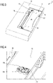
- Figure 1 shows a perspective schematic view of a passenger boarding and landing station 3 of a cabin 2 passenger cable transportation system 1.
- the station 3 comprises a couple of lateral guides 4 configured for containing and guiding the cabin along the advancing direction D in the station 3.
- the path, in plan view, of the guides is U-shaped and the station 3 can be a upstream or downstream station, where the cabin 2 inverts the direction of travel in a U.
- Figure 1 also shows a platform 6, arranged along a part of the outer guide 4 where passengers board and land.
- Figure 2 is a view of the cabin 2 along the advancing direction D and shows the arrangement of the cabin 2 in detail in relation to the lateral guides 4 at the passenger boarding and landing platform 6.
- the cabin 2 When advancing, as we know, the cabin 2 is suspended from the ground by means of an upper clamp 12 constrained to a cable, not shown, positioned above the roof 13 of the cabin 2. If the clamp 12 were to be released from the cable in the station 3, the cabin 2 is nonetheless suspended thanks to a roller 14 carrying the clamp 12 that rolls on a rail, not shown, positioned above the roof 13 of the cabin 2.
- the cabin 2 shown in figure 2 also comprises a footboard 10 for assisting passengers with boarding and landing, arranged outside the cabin entrance and exit door, not shown. Said footboard 10 is substantially in flush with the platform 6 or with the upper edge of the lateral guide 4. As we know, the cabin 2 is also equipped with an outside space 15 where passengers can put skis, rackets or other accessories.
- the lateral guides 4 at least level with the passenger boarding and landing part, have a distance between them that is slightly greater than the width of the cabin 2 in order to contain it and guide it, without blocking it.
- Said transversal clearance is represented in figure 2 by reference number 16 and is schematised as the distance present between the footboard 10 of the cabin 2 and the lateral guide 4 supporting the platform 6.
- Figure 2 shows a blocking device not part of the present invention configured for blocking the cabin 2 in relation to the lateral guides 4 at least along a direction T transversal to the advancing direction D level with at least one part of the station 3.
- a blocking device in the form of a lower clamp 23 (only outlined), which acts against a fin portion 24, projecting at the bottom outside the cabin 2 below the floor 25.
- the lower clamp 23 is shown fixed and planted in the ground.
- the clamp can be fixed to a lateral guide 4 and/or it can be housed on a slide or a guide parallel to the advancing direction D so as not to stop the advancing of the cabin 2.
- the lower clamp 23 can move, in a known manner, from an initial configuration of free insertion of the fin portion 24 in the mouth of the clamp 23 to a second configuration, wherein the mouth of the clamp 23 is clamped to hold the fin portion 24. In said last configuration, even though the clearance 16 is still present, the movement along the transversal T direction or rolling rotations of the cabin 2 are prevented from the start.
- the lower clamp 23 is substantially aligned with the upper clamp 12. However, the position of the clamp 23 can be different to the position shown as long as it prevents movement along the transversal T direction or rolling rotations of the cabin 2.
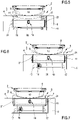
- Figures 3-10 show an embodiment of the blocking device of the present invention.
- figures 3-10 show a blocking device in the form of a pusher configured for selectively pushing the cabin 2 in abutment against at least one lateral guide 4.
- Figure 3 shows a broken view of an embodiment of the invention, which envisages a pusher 5 integrated into the platform 6, in the form of a rigid pusher 7.
- the pusher device 5 could be of a different type, for example not rigid but inflatable, or it could be integrated into the cabin 2, for example in the footboard 10 or in the lateral guide 4 opposite the platform 6.
- the rigid pusher 7 in figure 3 comprises a pushing head 8 facing the footboard 10 and a slide 11 onto which the pushing head 8 is mounted sprung and mobile, both in translation and in rotation.
- the pusher 5 is completely integrated with the platform 6 so that during the resting phases, it is hidden beneath the platform 6, not projecting from the lateral guide 4.
- the slide 11 is mounted onto tracks 17 (only partially visible) that are orthogonal to the lateral guide 4 and it is driven by a special motor 18.
- Figure 4 shows how the pushing head 8 is connected to the slide 11 according to said embodiment.
- a sliding block coupling 19 is put between the slide 11 and the pushing head 8, fitted with a preloaded spring 20.
- Said coupling is consequently configured so that until the first contact of the pushing head 8 with the footboard 10, the spring 20 keeps the pushing head 8 integral with the slide 11.
- the slide 11 advances even further while the pushing head 8 stays still against the footboard 10.
- This further advancing of the slide 11 results in the compression of the spring 20, which generates a corresponding pushing force on the cabin 2 that is then blocked against the lateral guide opposite 4.
- the pushing head 8 is connected to the sliding block 19 by means of a rotating plate 21, which allows the pushing plate 8 to rotate in relation to the slide 11 around an axis orthogonal to the platform 6.
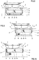
- Figures 5-10 show operating phases of the pusher 5 in figure 3 in two different conditions.
- the pushing head 8 is represented by a dotted pattern for clarity in these figures, also to highlight the movements of the slide 11 positioned below the pushing head 8.
- figures 5-7 show the state, wherein the cabin 2 is centred in relation to the pushing head 8 of the pusher device 5.
- Figure 5 outlines an initial phase wherein, after crossing part of the station 3, the cabin 2 comes level with the passenger boarding and landing platform 6.
- the advancing of the cabin 2 to the platform 6 is guaranteed by the presence of the clearance 16 present between the footboard 10 and the lateral guide 4.
- the cabin 2 is stopped level with the centre of the pushing head 8 and then the pusher device 5, hidden in the platform 6, is activated.
- FIG 6 shows an intermediate phase, wherein the pushing head 8 comes into contact with the footboard 10 of the cabin.
- the pushing head 8 moves integrally with the slide 11, which is driven, in turn, by the motor 18 along the guides 17.
- the cabin 2 comes into contact with the lateral guide 4 positioned on the opposite side in relation to the footboard 10, preventing the pushing head 8 from advancing.
- the motor 18 is configured and controlled so as to enforce a further advancing on the slide 11, which then translates in relation to the pushing head 8 thanks to the sprung sliding block 19. Said further advancing results in the compressing of the spring 20 that reacts by transferring the load to the pushing head 8, which transmits it, in turn, to the cabin 2 through the footboard 10.
- Figure 7 outlines this last phase wherein the spring 20 is compressed.
- the relative movement of the slide 11 in relation to the pushing head 8 is further guided by a couple of telescopic arms 21 having ends connected to the pushing head 8 and the slide 11 respectively.
- Figures 8-10 show operating phases of the pusher 5 in figure 3 , wherein the cabin 2 is nonetheless stopped with the footboard 10 not centred in relation to the pushing head 8 of the pusher device 5.
- Figure 8 outlines an initial phase, wherein, after crossing part of the station 3, the cabin 2 comes level with the passenger boarding and landing platform 6. The advancing of the cabin 2 towards the platform 6, as described previously, is guaranteed by the clearance 16 present between the footboard 10 and the lateral guide 4.
- Figure 9 shows an intermediate phase, wherein the pushing head 8 comes into contact with the footboard 10 of the cabin.
- the footboard 10 isn't centred in relation to the pushing head 8
- said initial contact doesn't take place level with the whole surface of the pushing head 8, but only along a short part of it, or only in a lateral point.
- the pushing head 8 moves integrally with the slide 11 driven, in turn, by the motor 18 along the guides 17.
- the subsequent advancing of the slide 11 makes the pushing head 8 rotate around the rotating plate 22, coupling the whole front surface of the footboard 10 with the pushing head 8.
- the telescopic rods 21 are hinged to the pushing head 8 and slide 11 so as to guide said rotation of the pushing head 8 in relation to the slide 11.
- Figure 10 outlines said last phase, wherein the pushing head 8 is inclined to couple along the whole development of the footboard 10 with the spring 20 is compressed.
Landscapes
- Engineering & Computer Science (AREA)
- Mechanical Engineering (AREA)
- Transportation (AREA)
- Platform Screen Doors And Railroad Systems (AREA)
- Seats For Vehicles (AREA)
- Ropes Or Cables (AREA)
Description
- The present invention relates to a cabin passenger cable transportation system.
- Passenger cable transportation systems known as cable cars comprise cabins, which advance along a path hauled by a hauling cable wound around relative pulleys. The cabins are suspended along the path of the system to a supporting cable and/or to a hauling and supporting cable. The path of the system is defined by a series of supporting towers and extends between one upstream station and one downstream station.
- At the upstream and downstream stations, as well as in other intermediate stations that may be planned along the path, passengers can board and land from the cabins by means of specific platforms.
- At each platform, the system comprises two lateral guides configured for containing and guiding the base of the cabin during the advancing of the cabin into the station. However, it is necessary to have a clearance between the cabin and the guides to keep the cabin at a sufficient distance to prevent the cabin from becoming stuck in the guides when advancing, particularly when the path defined by the guides is a curved path.
- In said conditions, i.e. with the cabin suspended from the ground by means of a constraint positioned above it and with a clearance present between the lateral guides and the cabin, oscillations are caused in the cabin by the passengers boarding and landing, particularly rolling oscillations, which make the cabin hit against the lateral guides.
- Although in some cases along the stations the cabin is temporarily decoupled from the hauling cable, also in said part of the path, the cabin is always suspended from the ground, for example by means of a rail along which a roller supporting the clamp runs. Therefore, also in this case the above oscillating phenomenon occurs.
- As stated previously, said oscillating movement consequently makes the cabin hit against the lateral guides generating an irritating noise and creating a sensation of instability and insecurity among the transiting passengers, especially those who do not travel frequently in cable cars.
- Also providing that boarding and landing occurs without the cabin advancing, often in cable systems boarding and landing occurs with the cabin advancing, the clearance present between the cabin and the lateral guides remains and so also in this case the foregoing oscillating movement is created in the cabin.
-
FR2752803 claim 1. According toFR2752803 - Consequently, it is an object of the present invention to realize a passenger cable transportation system, which allows to overcome the previously highlighted drawbacks of the prior art in a simple and cheap manner, both from a functional and constructional point of view.
- According to said objects, the present invention relates to a passenger cable transportation system according to
claim 1. - Detailing the elements listed above, by cabin we mean a space that is at least partially isolated from the surrounding area, which is driven by a hauling cable and suspended above the ground. The suspension of the cabin can be achieved by means of a supporting cable, or directly by means of the hauling cable, to which a clamp is coupled projecting from the roof of the cabin.
- As stated previously, at the stations, the cabin can be temporarily released from the supporting cable. However, also in this part of the path the cabin is suspended from the ground by means of a constraint positioned above the roof of the cabin, for example a rail where a roller supporting the clamp runs.
- In a cable car, passengers land or board the cabins through specific side doors, which are usually automatic sliding doors. A footboard is commonly envisaged at said doors, outside the cabin, to assist boarding and landing, as well as spaces for putting skis, rackets and/or other objects usually carried by passengers.
- Although seats may be foreseen inside the cabin, the unit of transport of the present invention must not be confused with a chairlift where no transport space is foreseen and wherein boarding occurs directly by sitting on the relative seat positioning oneself transversally on advancing.
- By passenger cabin boarding and landing station we mean a fixed installation equipped with a plurality of structures configured for allowing passengers to reach the boarding point easily, for example by means of steps or ramps, and staying there safely, for example by means of platforms or waiting rooms.
- The lateral guides are preferably made in form of substantially vertical metal banks, suitable for working with the lower portion of the cabins to guide and contain its movement inside the stations along an advancing direction. Said guides are usually U-shaped at the stations downstream and upstream in return systems, while they can present straight progressions in intermediate stations. However, in general, these lateral guides can have the desired progression depending on the path to be imposed on the cabin. The passenger boarding and landing platform is preferably an integral part of the upper edge of a lateral guide. A clearance, or distance transversal to the advancing direction is provided between the lateral guides and the cabin to prevent the cabin from becoming stuck in the lateral guides when advancing into the station.
- According to the invention, the system comprises a blocking device configured for blocking the cabin with respect to the lateral guides at least along a direction transversal to the advancing direction at at least one portion of the station, preferably at the passenger boarding and landing portion.
- The expression blocking the cabin is not understood to mean the simple interruption of the advancing of the cabin, but a constraint to prevent lateral rolling oscillations, or oscillations transversal to the advancing, of the cabin.
- Advantageously, in this way, passengers can board and land in a stable manner. In fact, the blocking device keeps the cabin still in relation to the lateral guides along the direction orthogonal to the advancing direction, consequently preventing oscillations from the beginning, particularly rolling oscillations when passengers are boarding and landing.
- The blocking device is made in the form of a pusher configured for selectively pushing the cabin in abutment against at least one lateral guide.
- In particular, according to the invention the station comprises a passenger cabin boarding and landing platform and the pusher device is integrated into the platform or into the lateral guide positioned immediately below said platform. The blocking device is made in the form of a pusher integrated into a portion of the platform or of the lateral guide connected to it. The pusher is able to selectively push the cabin against the opposite guide, moving from a retracted position, wherein it does not hinder the advancing of the cabin and it does not limit the clearance present between the lateral guides, to an extended position, which forces the cabin against the lateral guide opposite. Alternatively, the pusher can be integrated into the lateral guide opposite in relation to the one where boarding and landing is carried out.
- Advantageously, according to the invention, with the blocking device in the form of a pusher integrated into a guide, it is not necessary to make any modifications to the cabins present in the system.
- The pusher device comprises a rigid pusher, mobile from a projecting position, wherein it pushes the cabin in abutment against at least one lateral guide, and a retracting position, wherein the cabin is free to advance between the guides. Said rigid pusher is preferably of a translating type and comprises a pushing head, shaped in a complementary manner to the corresponding surface on which it acts. As stated previously, said rigid pusher is integrated into the station inside the platform or a lateral guide.
- Advantageously, thanks to a rigid pusher shaped in a complementary manner to the corresponding surface on which it acts the pushing force is evenly distributed along the whole contact area avoiding excessive local loading points, which could damage the structure of the cabin or the lateral guide.
- The cabin preferably comprises a footboard to assist passengers boarding and landing and the pusher device integrated in the platform and/or relative lateral guide is arranged in flush with the footboard.
- Advantageously, in this case, the pusher creates a mobile platform, which, when extracted, creates a continuous floor for passengers in the absence of lights between the footboard and the mobile platform.
- The pushing head and the corresponding surface on which it acts comprise shapes respectively concave and convex. The pushing head is integrated inside the platform or a lateral guide and the surface on which it acts is a portion of the cabin, preferably the footboard.
- Advantageously, thanks to the geometric coupling between corresponding concave and convex surfaces, spontaneous centering of the cabin occurs in relation to the pusher.
- The pushing head of the pusher device is mounted mobile translating in a sprung manner, on a slide orthogonally translating in relation to the progression of the lateral guide. The pushing head and the slide are housed in the platform or in the lateral guide and are configured so that they are integral with each other until contact with the cabin. After contact, the slide is made to advance further in relation to the pushing head to generate a pushing force against the cabin, which derives from the partial compression of a spring present between the pushing head and the slide.
- Advantageously, in this way, both the contact and pushing phase do not occur abruptly, but in a sprung manner without transmitting lateral impulses to the cabin.
- In particular, in the embodiment just described, the pushing head can also be rotatable in relation to the slide, around an axis orthogonal to the platform in such a manner that also when the cabin is not centred in relation to the pushing head, the advancing movement of the slide after the initial contact with the cabin generates a rotation of the pushing head so that it adheres perfectly to the cabin.
- All of the embodiments described thus far, which include a pusher, can of course be used envisaging the temporary stopping of the cabin in the station during operation of the pusher device.
- However, the present invention also envisages the option of the continuous advancing of the cabin in the station also during operation of the pusher device.
- In particular, the pusher device and the lateral guides can, in fact, be configured for allowing the continuous movement of the cabin in the station also in the part in the cabin that is pressed against the lateral guide. For example, the contact surface between the cabin and the lateral guides and the surface between the cabin and the pusher device can comprise a band or a mobile belt or they can comprise rolling rollers.
- Advantageously, according to said embodiment, the cabin is not necessarily stopped and, at the same time, the development of oscillations is prevented.
- In particular, according to one embodiment of the invention, the system can comprise a couple of pusher devices acting on both sides of the cabin.
- Advantageously, according to said embodiment of the invention, the cabin is centred in the guides and the floor inside the cabin is kept horizontal.
- Further characteristics and advantages of the present invention will become clear from the following description of an example of an embodiment, which is not limiting, with reference to the figures in the accompanying drawings, wherein:
-
figure 1 is a perspective schematic view of a passenger boarding and landing station of a passenger cable transportation system; -
figure 2 is an enlarged schematic view of the cabin infigure 1 along the advancing direction, wherein an embodiment of a blocking device not part of the invention is visible in the form of a lower clamp; -
figures 3 and 4 show schematic views of an embodiment of a blocking device according to the present invention in the form of a pusher; -
figures 5-10 schematically show operating phases of the passenger cable transportation system, wherein the boarding and landing platform is equipped with the pusher according tofigure 3 . -
Figure 1 shows a perspective schematic view of a passenger boarding andlanding station 3 of acabin 2 passengercable transportation system 1. Thestation 3 comprises a couple oflateral guides 4 configured for containing and guiding the cabin along the advancing direction D in thestation 3. Infigure 1 , the path, in plan view, of the guides is U-shaped and thestation 3 can be a upstream or downstream station, where thecabin 2 inverts the direction of travel in a U.Figure 1 also shows aplatform 6, arranged along a part of theouter guide 4 where passengers board and land. -
Figure 2 is a view of thecabin 2 along the advancing direction D and shows the arrangement of thecabin 2 in detail in relation to the lateral guides 4 at the passenger boarding andlanding platform 6. - When advancing, as we know, the
cabin 2 is suspended from the ground by means of anupper clamp 12 constrained to a cable, not shown, positioned above theroof 13 of thecabin 2. If theclamp 12 were to be released from the cable in thestation 3, thecabin 2 is nonetheless suspended thanks to aroller 14 carrying theclamp 12 that rolls on a rail, not shown, positioned above theroof 13 of thecabin 2. Thecabin 2 shown infigure 2 also comprises afootboard 10 for assisting passengers with boarding and landing, arranged outside the cabin entrance and exit door, not shown. Saidfootboard 10 is substantially in flush with theplatform 6 or with the upper edge of thelateral guide 4. As we know, thecabin 2 is also equipped with anoutside space 15 where passengers can put skis, rackets or other accessories. - As we can see in
figure 2 , the lateral guides 4, at least level with the passenger boarding and landing part, have a distance between them that is slightly greater than the width of thecabin 2 in order to contain it and guide it, without blocking it. Said transversal clearance is represented infigure 2 byreference number 16 and is schematised as the distance present between thefootboard 10 of thecabin 2 and thelateral guide 4 supporting theplatform 6. -
Figure 2 shows a blocking device not part of the present invention configured for blocking thecabin 2 in relation to the lateral guides 4 at least along a direction T transversal to the advancing direction D level with at least one part of thestation 3. In particular,figure 2 shows a blocking device in the form of a lower clamp 23 (only outlined), which acts against afin portion 24, projecting at the bottom outside thecabin 2 below thefloor 25. In said figure, thelower clamp 23 is shown fixed and planted in the ground. However, the clamp can be fixed to alateral guide 4 and/or it can be housed on a slide or a guide parallel to the advancing direction D so as not to stop the advancing of thecabin 2. Thelower clamp 23 can move, in a known manner, from an initial configuration of free insertion of thefin portion 24 in the mouth of theclamp 23 to a second configuration, wherein the mouth of theclamp 23 is clamped to hold thefin portion 24. In said last configuration, even though theclearance 16 is still present, the movement along the transversal T direction or rolling rotations of thecabin 2 are prevented from the start. Infigure 2 , thelower clamp 23 is substantially aligned with theupper clamp 12. However, the position of theclamp 23 can be different to the position shown as long as it prevents movement along the transversal T direction or rolling rotations of thecabin 2. -
Figures 3-10 show an embodiment of the blocking device of the present invention. In particular,figures 3-10 show a blocking device in the form of a pusher configured for selectively pushing thecabin 2 in abutment against at least onelateral guide 4. -
Figure 3 shows a broken view of an embodiment of the invention, which envisages apusher 5 integrated into theplatform 6, in the form of arigid pusher 7. Of course,figure 3 is only a non-limiting example of the invention, according to which, for example, thepusher device 5 could be of a different type, for example not rigid but inflatable, or it could be integrated into thecabin 2, for example in thefootboard 10 or in thelateral guide 4 opposite theplatform 6. - The
rigid pusher 7 infigure 3 comprises a pushinghead 8 facing thefootboard 10 and aslide 11 onto which the pushinghead 8 is mounted sprung and mobile, both in translation and in rotation. In said example, thepusher 5 is completely integrated with theplatform 6 so that during the resting phases, it is hidden beneath theplatform 6, not projecting from thelateral guide 4. Theslide 11 is mounted onto tracks 17 (only partially visible) that are orthogonal to thelateral guide 4 and it is driven by aspecial motor 18. -
Figure 4 shows how the pushinghead 8 is connected to theslide 11 according to said embodiment. In particular, a slidingblock coupling 19 is put between theslide 11 and the pushinghead 8, fitted with apreloaded spring 20. Said coupling is consequently configured so that until the first contact of the pushinghead 8 with thefootboard 10, thespring 20 keeps the pushinghead 8 integral with theslide 11. After the first contact, and during the initial pushing phase of thecabin 2, theslide 11 advances even further while the pushinghead 8 stays still against thefootboard 10. This further advancing of theslide 11 results in the compression of thespring 20, which generates a corresponding pushing force on thecabin 2 that is then blocked against the lateral guide opposite 4. Again, infigure 4 we can see how the pushinghead 8 is connected to the slidingblock 19 by means of arotating plate 21, which allows the pushingplate 8 to rotate in relation to theslide 11 around an axis orthogonal to theplatform 6. -
Figures 5-10 show operating phases of thepusher 5 infigure 3 in two different conditions. The pushinghead 8 is represented by a dotted pattern for clarity in these figures, also to highlight the movements of theslide 11 positioned below the pushinghead 8. In particular,figures 5-7 show the state, wherein thecabin 2 is centred in relation to the pushinghead 8 of thepusher device 5. -
Figure 5 outlines an initial phase wherein, after crossing part of thestation 3, thecabin 2 comes level with the passenger boarding andlanding platform 6. The advancing of thecabin 2 to theplatform 6 is guaranteed by the presence of theclearance 16 present between thefootboard 10 and thelateral guide 4. According to this example, thecabin 2 is stopped level with the centre of the pushinghead 8 and then thepusher device 5, hidden in theplatform 6, is activated. -
Figure 6 shows an intermediate phase, wherein the pushinghead 8 comes into contact with thefootboard 10 of the cabin. In particular, during the approaching movement the pushinghead 8 moves integrally with theslide 11, which is driven, in turn, by themotor 18 along theguides 17. - After contact between the pushing
head 8 and thefootboard 10, thecabin 2 comes into contact with thelateral guide 4 positioned on the opposite side in relation to thefootboard 10, preventing the pushinghead 8 from advancing. In this state, themotor 18 is configured and controlled so as to enforce a further advancing on theslide 11, which then translates in relation to the pushinghead 8 thanks to the sprung slidingblock 19. Said further advancing results in the compressing of thespring 20 that reacts by transferring the load to the pushinghead 8, which transmits it, in turn, to thecabin 2 through thefootboard 10. -
Figure 7 outlines this last phase wherein thespring 20 is compressed. The relative movement of theslide 11 in relation to the pushinghead 8 is further guided by a couple oftelescopic arms 21 having ends connected to the pushinghead 8 and theslide 11 respectively. -
Figures 8-10 show operating phases of thepusher 5 infigure 3 , wherein thecabin 2 is nonetheless stopped with thefootboard 10 not centred in relation to the pushinghead 8 of thepusher device 5. -
Figure 8 outlines an initial phase, wherein, after crossing part of thestation 3, thecabin 2 comes level with the passenger boarding andlanding platform 6. The advancing of thecabin 2 towards theplatform 6, as described previously, is guaranteed by theclearance 16 present between thefootboard 10 and thelateral guide 4. -
Figure 9 shows an intermediate phase, wherein the pushinghead 8 comes into contact with thefootboard 10 of the cabin. As thefootboard 10 isn't centred in relation to the pushinghead 8, said initial contact doesn't take place level with the whole surface of the pushinghead 8, but only along a short part of it, or only in a lateral point. As with the previous example, during the approaching movement, the pushinghead 8 moves integrally with theslide 11 driven, in turn, by themotor 18 along theguides 17. - The subsequent advancing of the
slide 11 makes the pushinghead 8 rotate around the rotatingplate 22, coupling the whole front surface of thefootboard 10 with the pushinghead 8. Thetelescopic rods 21 are hinged to the pushinghead 8 and slide 11 so as to guide said rotation of the pushinghead 8 in relation to theslide 11. - Said rotation, and the subsequent advancing of the
slide 11, result in the compression of thespring 20, which, as in the previous case, reacts by transferring the load to the pushinghead 8, transmitting it, in turn, to thecabin 2 through thefootboard 10. -
Figure 10 outlines said last phase, wherein the pushinghead 8 is inclined to couple along the whole development of thefootboard 10 with thespring 20 is compressed. - Finally, it is clear that modifications and variations can be made to the passenger cable transportation system described here without going beyond the scope of the accompanying claims.
Claims (5)
- A passenger cable transportation system, the cable system (1) comprising:- at least one cabin (2) for transporting passengers;- at least one station (3) for passengers boarding and landing from the cabin (2);- a hauling cable driving the cabin (2);- two lateral guides (4) facing each other and configured for guiding the cabin (2) into the station (3) along an advancing direction (D), wherein the cabin (2) is suspended from the ground and a clearance (16) transversal to the advancing direction (D) is present between the lateral guides (4) and the cabin (2) so that the cabin (2) is prevented from becoming stuck in the lateral guides (4) when advancing into the station (3);the system (1) moreover comprises:- at least one blocking device configured for blocking the cabin (2) in relation to the lateral guides (4) at least along a direction transversal (T) to the advancing direction (D) level with at least one part of the station (3);wherein the blocking device comprises a pusher configured for selectively pushing the cabin (2) in abutment against at least one lateral guide (4);wherein the station (3) comprises a platform (6) for passengers boarding and landing from the cabin (2) level with at least one portion of a lateral guide (4), the pusher (5) being integrated in the platform (6) and/or in the relative lateral guide (4);wherein the pusher comprises a rigid pusher (7) mobile from a projecting position, wherein it pushes the cabin (2) in abutment against at least one lateral guide (4), and a retracting position, wherein the cabin (2) is free to advance between the guides (4);wherein the rigid pusher (7) comprises a pushing head (8) having an outer profile shaped in a complementary manner to the corresponding outer profile of the surface (9) on which it acts;wherein the pushing head (8) and the corresponding surface on which it acts (9) comprise shapes respectively concave and convex;wherein the pushing head (8) is sprung and mounted mobile on a slide (11) translating orthogonally in relation to the development of the lateral guide (4), the pushing head (8) and the slide (11) being configured in such a manner that they are integral with each other until contact with the cabin (2) and after contact, the slide (11) advances in relation to the pushing head (8) to generate a pushing force against the cabin.
- A system as claimed in claim 1, wherein the pushing head (8) is also rotatable in relation to the slide (11) in such a manner that also when the cabin (2) is not centred in relation to the pushing head (8), the advancing movement of the slide (11) after the initial contact with the cabin (2) generates a rotation of the pushing head (8) so that it adheres to the cabin (2).
- A system as claimed in any one of the foregoing claims from 1 to 2, wherein the cabin (2) comprises a footboard (10) for passengers boarding and landing, the pusher (5) being arranged flush with the footboard (10).
- A system as claimed in any one of the foregoing claims from 1 to 3, wherein the pusher (5) and the lateral guides (4) are configured for allowing the continuous advancing of the cabin (2) into the station (3).
- A system as claimed in any one of the foregoing claims from 1 to 4, wherein the system (1) comprises at least one couple of pushers (5) configured for selectively pushing the cabin (2) in abutment against both of the lateral guides (4) .
Applications Claiming Priority (1)
| Application Number | Priority Date | Filing Date | Title |
|---|---|---|---|
| IT102016000094933A IT201600094933A1 (en) | 2016-09-21 | 2016-09-21 | ROPE SYSTEM FOR PASSENGER TRANSPORTATION |
Publications (3)
| Publication Number | Publication Date |
|---|---|
| EP3299243A1 EP3299243A1 (en) | 2018-03-28 |
| EP3299243B1 EP3299243B1 (en) | 2019-05-29 |
| EP3299243B2 true EP3299243B2 (en) | 2022-04-27 |
Family
ID=57909926
Family Applications (1)
| Application Number | Title | Priority Date | Filing Date |
|---|---|---|---|
| EP17192487.1A Active EP3299243B2 (en) | 2016-09-21 | 2017-09-21 | Passenger cable transportation system |
Country Status (4)
| Country | Link |
|---|---|
| US (1) | US10814888B2 (en) |
| EP (1) | EP3299243B2 (en) |
| CN (1) | CN107856678B (en) |
| IT (1) | IT201600094933A1 (en) |
Families Citing this family (5)
| Publication number | Priority date | Publication date | Assignee | Title |
|---|---|---|---|---|
| AT523619B1 (en) | 2020-02-26 | 2024-06-15 | Innova Patent Gmbh | Cable car with cabin stabilization |
| FR3075741B1 (en) * | 2017-12-21 | 2019-12-20 | Creissels Technologies | STATION OF A CONVEYOR OF AIR VEHICLES ON CABLE |
| US12485934B2 (en) * | 2019-06-05 | 2025-12-02 | Leitner S.P.A. | Hybrid cable/rail transportation system |
| ES3038641T3 (en) * | 2022-02-15 | 2025-10-14 | Innova Patent Gmbh | Cableway with fall protection |
| EP4275984A1 (en) | 2022-05-10 | 2023-11-15 | Bartholet Maschinenbau AG | Transportation operating equipment for fastening to a cable of a cableway installation, cableway comprising transportation operating equipment, method for damping the deflection of transportation operating equipment by means of a cableway and use of a transportation operating equipment |
Citations (3)
| Publication number | Priority date | Publication date | Assignee | Title |
|---|---|---|---|---|
| JPS49149448U (en) † | 1973-04-26 | 1974-12-24 | ||
| FR2546836A1 (en) † | 1983-06-03 | 1984-12-07 | Pomagalski Sa | Cableway station |
| JPH0287669U (en) † | 1988-12-27 | 1990-07-11 |
Family Cites Families (32)
| Publication number | Priority date | Publication date | Assignee | Title |
|---|---|---|---|---|
| US270508A (en) * | 1883-01-09 | Traction rope railway | ||
| DE473571C (en) | 1927-05-14 | 1929-03-22 | Franz Kruckenberg Dipl Ing | Device for guiding high-speed railways in vertical hanging positions, especially on stations |
| AT243851B (en) | 1963-09-05 | 1965-12-10 | Allgemeiner Zentralver Zur Foe | Envelope cabin, in particular for chair lifts |
| US3964118A (en) * | 1975-04-28 | 1976-06-22 | Marriott Corporation | Cargo transfer vehicle with double angle catwalk adjustment |
| DE2712927A1 (en) * | 1977-03-24 | 1978-09-28 | Messerschmitt Boelkow Blohm | Station for underground rail system using light vehicles - has hoist including pressure medium activated arm and platform extending to edge of vehicle floor |
| DE2712921C2 (en) * | 1977-03-24 | 1986-02-13 | Wesero Maschinenbau GmbH, 4322 Sprockhövel | Device for brushing plate-shaped workpieces |
| DE2844624C2 (en) | 1978-10-13 | 1982-10-21 | Duewag AG, 4150 Krefeld | Device for positioning an overhead conveyor cabin |
| DE2844623C2 (en) * | 1978-10-13 | 1983-11-10 | Duewag AG, 4150 Krefeld | Overhead conveyor with devices for positioning a car transversely to the direction of travel in relation to a station |
| JPS5842060B2 (en) | 1979-02-05 | 1983-09-16 | 日産自動車株式会社 | Rolling stabilization device for suspended vehicles |
| US4369714A (en) | 1979-11-27 | 1983-01-25 | Nissan Motor Co., Ltd. | Cable car docking sway arrester mechanism |
| FR2496047A1 (en) | 1980-12-15 | 1982-06-18 | Sovam | ACCORDIATION SYSTEM FOR PASSENGER TRANSPORT VEHICLES BETWEEN AEROGARE AND AN AIRCRAFT |
| US4741086A (en) | 1985-08-29 | 1988-05-03 | The B. F. Goodrich Company | Pneumatic lift jack |
| JPS6294463A (en) * | 1985-10-18 | 1987-04-30 | ポマガルスキ−、ソシエテ、アノニム | Ropeway station |
| JPH0287669A (en) | 1988-09-26 | 1990-03-28 | Mitsubishi Electric Corp | Semiconductor device |
| US5651569A (en) * | 1995-10-18 | 1997-07-29 | Molnar; Steve | Inflatable bumper system |
| FR2752803B1 (en) * | 1996-08-28 | 2003-06-06 | Pomagalski Sa | METHOD FOR INCREASING THE HOURLY RATE OF PERSONS BORROWING VEHICLES CARRIED BY CABLE AND INSTALLATION FOR IMPLEMENTING IT |
| ES2179608T3 (en) * | 1999-03-10 | 2003-01-16 | Holzl Constr Funivie S R L | DEPARTURE AND ARRIVAL STATION FOR AN IDA AND RETURN AIR FUNCTION AS WELL AS ALSO A CABIN TO TRANSPORT PASSENGERS UP OR DOWN IN SUCH STATION. |
| US6513418B1 (en) | 2000-08-07 | 2003-02-04 | Bfs Diversified Products, Lls | Air actuator |
| US6360393B1 (en) | 2000-09-14 | 2002-03-26 | Kelley Company, Inc. | Method for converting a dock leveler to a dock leveler operated with an inflatable member and a dock leveler produced by the same |
| JP4511073B2 (en) * | 2001-03-30 | 2010-07-28 | 日本ケーブル株式会社 | Swivel moving platform |
| JP2003072538A (en) | 2001-09-04 | 2003-03-12 | Anzen Sakudo Kk | Carrier fixing device at stop |
| JP2003127854A (en) * | 2001-10-24 | 2003-05-08 | Anzen Sakudo Kk | Equipment fixing device for station |
| ATE355212T1 (en) | 2004-09-23 | 2006-03-15 | Innova Patent Gmbh | DEVICE FOR FASTENING A MOVING EQUIPMENT OF A CABLEWAY SYSTEM TO A HANGING ROD |
| US7503089B2 (en) | 2005-04-05 | 2009-03-17 | Rite-Hite Holding Corporation | Inflatable actuator for a dock leveler deck |
| US20070034105A1 (en) | 2005-08-09 | 2007-02-15 | Jean-Francois Mugnier | Aerial ropeway transport methods |
| AT502753A3 (en) | 2005-09-27 | 2009-01-15 | Innova Patent Gmbh | ROPE RAILWAY SYSTEM WITH ROTATABLE DRIVING MEANS |
| JP5398578B2 (en) * | 2010-02-23 | 2014-01-29 | 日本ケーブル株式会社 | Mobile steps on cableway platform |
| JP5825669B2 (en) | 2011-10-28 | 2015-12-02 | 日本ケーブル株式会社 | Suspension control device for suspension type passenger car |
| KR20130125541A (en) * | 2012-05-09 | 2013-11-19 | 김종찬 | Safety foot hold type cable car platform structure |
| KR20130125540A (en) * | 2012-05-09 | 2013-11-19 | 김종찬 | Safety foot hold type cable car structure |
| US9802625B2 (en) * | 2014-04-10 | 2017-10-31 | National Railroad Passenger Corp. | Method and system for drive for setback platform system |
| FR3027272B1 (en) * | 2014-10-15 | 2018-04-13 | Poma | CABIN ATTACHMENT DEVICE FOR CABLE TRACING, VEHICLE EQUIPPED WITH SUCH A DEVICE, AND CABLE TRANSPORTATION SYSTEM COMPRISING SUCH A VEHICLE |
-
2016
- 2016-09-21 IT IT102016000094933A patent/IT201600094933A1/en unknown
-
2017
- 2017-09-20 US US15/710,155 patent/US10814888B2/en active Active
- 2017-09-20 CN CN201710858307.9A patent/CN107856678B/en active Active
- 2017-09-21 EP EP17192487.1A patent/EP3299243B2/en active Active
Patent Citations (3)
| Publication number | Priority date | Publication date | Assignee | Title |
|---|---|---|---|---|
| JPS49149448U (en) † | 1973-04-26 | 1974-12-24 | ||
| FR2546836A1 (en) † | 1983-06-03 | 1984-12-07 | Pomagalski Sa | Cableway station |
| JPH0287669U (en) † | 1988-12-27 | 1990-07-11 |
Also Published As
| Publication number | Publication date |
|---|---|
| US10814888B2 (en) | 2020-10-27 |
| US20180079431A1 (en) | 2018-03-22 |
| EP3299243A1 (en) | 2018-03-28 |
| EP3299243B1 (en) | 2019-05-29 |
| CN107856678A (en) | 2018-03-30 |
| IT201600094933A1 (en) | 2018-03-21 |
| CN107856678B (en) | 2021-02-09 |
Similar Documents
| Publication | Publication Date | Title |
|---|---|---|
| EP3299243B2 (en) | Passenger cable transportation system | |
| EP3747722B1 (en) | Hybrid cable/rail transportation system | |
| US6360669B1 (en) | Installation for moving persons from a mountain station into a valley station | |
| AU2013206586B2 (en) | Station for a cable railway system | |
| RU2653653C1 (en) | Cable way for passenger transportation | |
| CN110588671B (en) | Trolley for supporting a transport unit suspended on a guide of a transport system and transport system comprising such a trolley | |
| CN104442835A (en) | Cable car system for conveying persons | |
| US5827123A (en) | Carousel for carnivals and amusement parks | |
| US11148597B2 (en) | Rail vehicle, method for producing a rail vehicle, and use of a scissor mechanism in a boarding arrangement | |
| US8960096B2 (en) | Chair-lift station having a high flow and small dimensions | |
| EP3860735B1 (en) | Ride evacuation systems and methods | |
| CN105523048B (en) | Device for attaching a compartment, cable car and installation equipped with such a device | |
| JPS6118470B2 (en) | ||
| US4397242A (en) | Cable driven shuttle system having guideways of different lengths and method for its use | |
| KR200443680Y1 (en) | Aircraft emergency landing guidance device | |
| JP3157232B2 (en) | Cableway mobile platform | |
| WO2022034325A1 (en) | Ramp system | |
| JP2026512755A (en) | Guide track, amusement machine equipped with such guide track, and method for operating such amusement machine. | |
| JPH0431162A (en) | Elevator type platform for deep underground railway station | |
| HK40128944A (en) | Guideway, ride with a guideway of this type and method for operating a ride of this type | |
| HK40060722A (en) | Conveying system of an escalator | |
| GB2539624A (en) | An access ramp | |
| JPH06206537A (en) | Movable circular arc platform device for ropeway | |
| FR2731973A1 (en) | Storage installation for overhead cable cars |
Legal Events
| Date | Code | Title | Description |
|---|---|---|---|
| PUAI | Public reference made under article 153(3) epc to a published international application that has entered the european phase |
Free format text: ORIGINAL CODE: 0009012 |
|
| STAA | Information on the status of an ep patent application or granted ep patent |
Free format text: STATUS: THE APPLICATION HAS BEEN PUBLISHED |
|
| AK | Designated contracting states |
Kind code of ref document: A1 Designated state(s): AL AT BE BG CH CY CZ DE DK EE ES FI FR GB GR HR HU IE IS IT LI LT LU LV MC MK MT NL NO PL PT RO RS SE SI SK SM TR |
|
| AX | Request for extension of the european patent |
Extension state: BA ME |
|
| STAA | Information on the status of an ep patent application or granted ep patent |
Free format text: STATUS: REQUEST FOR EXAMINATION WAS MADE |
|
| 17P | Request for examination filed |
Effective date: 20180926 |
|
| RBV | Designated contracting states (corrected) |
Designated state(s): AL AT BE BG CH CY CZ DE DK EE ES FI FR GB GR HR HU IE IS IT LI LT LU LV MC MK MT NL NO PL PT RO RS SE SI SK SM TR |
|
| RIC1 | Information provided on ipc code assigned before grant |
Ipc: B61B 1/02 20060101ALI20181012BHEP Ipc: B61K 1/00 20060101ALI20181012BHEP Ipc: B61B 12/00 20060101ALI20181012BHEP Ipc: B61B 12/04 20060101AFI20181012BHEP |
|
| GRAP | Despatch of communication of intention to grant a patent |
Free format text: ORIGINAL CODE: EPIDOSNIGR1 |
|
| STAA | Information on the status of an ep patent application or granted ep patent |
Free format text: STATUS: GRANT OF PATENT IS INTENDED |
|
| INTG | Intention to grant announced |
Effective date: 20181213 |
|
| GRAS | Grant fee paid |
Free format text: ORIGINAL CODE: EPIDOSNIGR3 |
|
| GRAA | (expected) grant |
Free format text: ORIGINAL CODE: 0009210 |
|
| STAA | Information on the status of an ep patent application or granted ep patent |
Free format text: STATUS: THE PATENT HAS BEEN GRANTED |
|
| AK | Designated contracting states |
Kind code of ref document: B1 Designated state(s): AL AT BE BG CH CY CZ DE DK EE ES FI FR GB GR HR HU IE IS IT LI LT LU LV MC MK MT NL NO PL PT RO RS SE SI SK SM TR |
|
| REG | Reference to a national code |
Ref country code: GB Ref legal event code: FG4D |
|
| REG | Reference to a national code |
Ref country code: CH Ref legal event code: EP |
|
| REG | Reference to a national code |
Ref country code: AT Ref legal event code: REF Ref document number: 1138081 Country of ref document: AT Kind code of ref document: T Effective date: 20190615 |
|
| REG | Reference to a national code |
Ref country code: DE Ref legal event code: R096 Ref document number: 602017004199 Country of ref document: DE |
|
| REG | Reference to a national code |
Ref country code: IE Ref legal event code: FG4D |
|
| REG | Reference to a national code |
Ref country code: CH Ref legal event code: NV Representative=s name: HEPP WENGER RYFFEL AG, CH |
|
| REG | Reference to a national code |
Ref country code: NL Ref legal event code: MP Effective date: 20190529 |
|
| REG | Reference to a national code |
Ref country code: LT Ref legal event code: MG4D |
|
| PG25 | Lapsed in a contracting state [announced via postgrant information from national office to epo] |
Ref country code: FI Free format text: LAPSE BECAUSE OF FAILURE TO SUBMIT A TRANSLATION OF THE DESCRIPTION OR TO PAY THE FEE WITHIN THE PRESCRIBED TIME-LIMIT Effective date: 20190529 Ref country code: NO Free format text: LAPSE BECAUSE OF FAILURE TO SUBMIT A TRANSLATION OF THE DESCRIPTION OR TO PAY THE FEE WITHIN THE PRESCRIBED TIME-LIMIT Effective date: 20190829 Ref country code: HR Free format text: LAPSE BECAUSE OF FAILURE TO SUBMIT A TRANSLATION OF THE DESCRIPTION OR TO PAY THE FEE WITHIN THE PRESCRIBED TIME-LIMIT Effective date: 20190529 Ref country code: SE Free format text: LAPSE BECAUSE OF FAILURE TO SUBMIT A TRANSLATION OF THE DESCRIPTION OR TO PAY THE FEE WITHIN THE PRESCRIBED TIME-LIMIT Effective date: 20190529 Ref country code: AL Free format text: LAPSE BECAUSE OF FAILURE TO SUBMIT A TRANSLATION OF THE DESCRIPTION OR TO PAY THE FEE WITHIN THE PRESCRIBED TIME-LIMIT Effective date: 20190529 Ref country code: ES Free format text: LAPSE BECAUSE OF FAILURE TO SUBMIT A TRANSLATION OF THE DESCRIPTION OR TO PAY THE FEE WITHIN THE PRESCRIBED TIME-LIMIT Effective date: 20190529 Ref country code: PT Free format text: LAPSE BECAUSE OF FAILURE TO SUBMIT A TRANSLATION OF THE DESCRIPTION OR TO PAY THE FEE WITHIN THE PRESCRIBED TIME-LIMIT Effective date: 20190930 Ref country code: LT Free format text: LAPSE BECAUSE OF FAILURE TO SUBMIT A TRANSLATION OF THE DESCRIPTION OR TO PAY THE FEE WITHIN THE PRESCRIBED TIME-LIMIT Effective date: 20190529 |
|
| PG25 | Lapsed in a contracting state [announced via postgrant information from national office to epo] |
Ref country code: BG Free format text: LAPSE BECAUSE OF FAILURE TO SUBMIT A TRANSLATION OF THE DESCRIPTION OR TO PAY THE FEE WITHIN THE PRESCRIBED TIME-LIMIT Effective date: 20190829 Ref country code: GR Free format text: LAPSE BECAUSE OF FAILURE TO SUBMIT A TRANSLATION OF THE DESCRIPTION OR TO PAY THE FEE WITHIN THE PRESCRIBED TIME-LIMIT Effective date: 20190830 Ref country code: RS Free format text: LAPSE BECAUSE OF FAILURE TO SUBMIT A TRANSLATION OF THE DESCRIPTION OR TO PAY THE FEE WITHIN THE PRESCRIBED TIME-LIMIT Effective date: 20190529 Ref country code: LV Free format text: LAPSE BECAUSE OF FAILURE TO SUBMIT A TRANSLATION OF THE DESCRIPTION OR TO PAY THE FEE WITHIN THE PRESCRIBED TIME-LIMIT Effective date: 20190529 |
|
| PG25 | Lapsed in a contracting state [announced via postgrant information from national office to epo] |
Ref country code: CZ Free format text: LAPSE BECAUSE OF FAILURE TO SUBMIT A TRANSLATION OF THE DESCRIPTION OR TO PAY THE FEE WITHIN THE PRESCRIBED TIME-LIMIT Effective date: 20190529 Ref country code: RO Free format text: LAPSE BECAUSE OF FAILURE TO SUBMIT A TRANSLATION OF THE DESCRIPTION OR TO PAY THE FEE WITHIN THE PRESCRIBED TIME-LIMIT Effective date: 20190529 Ref country code: SK Free format text: LAPSE BECAUSE OF FAILURE TO SUBMIT A TRANSLATION OF THE DESCRIPTION OR TO PAY THE FEE WITHIN THE PRESCRIBED TIME-LIMIT Effective date: 20190529 Ref country code: EE Free format text: LAPSE BECAUSE OF FAILURE TO SUBMIT A TRANSLATION OF THE DESCRIPTION OR TO PAY THE FEE WITHIN THE PRESCRIBED TIME-LIMIT Effective date: 20190529 Ref country code: DK Free format text: LAPSE BECAUSE OF FAILURE TO SUBMIT A TRANSLATION OF THE DESCRIPTION OR TO PAY THE FEE WITHIN THE PRESCRIBED TIME-LIMIT Effective date: 20190529 Ref country code: NL Free format text: LAPSE BECAUSE OF FAILURE TO SUBMIT A TRANSLATION OF THE DESCRIPTION OR TO PAY THE FEE WITHIN THE PRESCRIBED TIME-LIMIT Effective date: 20190529 |
|
| REG | Reference to a national code |
Ref country code: DE Ref legal event code: R026 Ref document number: 602017004199 Country of ref document: DE |
|
| PLBI | Opposition filed |
Free format text: ORIGINAL CODE: 0009260 |
|
| PG25 | Lapsed in a contracting state [announced via postgrant information from national office to epo] |
Ref country code: SM Free format text: LAPSE BECAUSE OF FAILURE TO SUBMIT A TRANSLATION OF THE DESCRIPTION OR TO PAY THE FEE WITHIN THE PRESCRIBED TIME-LIMIT Effective date: 20190529 |
|
| PLAX | Notice of opposition and request to file observation + time limit sent |
Free format text: ORIGINAL CODE: EPIDOSNOBS2 |
|
| 26 | Opposition filed |
Opponent name: DOPPELMAYR SEILBAHNEN GMBH Effective date: 20200207 |
|
| PG25 | Lapsed in a contracting state [announced via postgrant information from national office to epo] |
Ref country code: TR Free format text: LAPSE BECAUSE OF FAILURE TO SUBMIT A TRANSLATION OF THE DESCRIPTION OR TO PAY THE FEE WITHIN THE PRESCRIBED TIME-LIMIT Effective date: 20190529 |
|
| PG25 | Lapsed in a contracting state [announced via postgrant information from national office to epo] |
Ref country code: PL Free format text: LAPSE BECAUSE OF FAILURE TO SUBMIT A TRANSLATION OF THE DESCRIPTION OR TO PAY THE FEE WITHIN THE PRESCRIBED TIME-LIMIT Effective date: 20190529 |
|
| PG25 | Lapsed in a contracting state [announced via postgrant information from national office to epo] |
Ref country code: SI Free format text: LAPSE BECAUSE OF FAILURE TO SUBMIT A TRANSLATION OF THE DESCRIPTION OR TO PAY THE FEE WITHIN THE PRESCRIBED TIME-LIMIT Effective date: 20190529 Ref country code: MC Free format text: LAPSE BECAUSE OF FAILURE TO SUBMIT A TRANSLATION OF THE DESCRIPTION OR TO PAY THE FEE WITHIN THE PRESCRIBED TIME-LIMIT Effective date: 20190529 |
|
| PLBB | Reply of patent proprietor to notice(s) of opposition received |
Free format text: ORIGINAL CODE: EPIDOSNOBS3 |
|
| PG25 | Lapsed in a contracting state [announced via postgrant information from national office to epo] |
Ref country code: LU Free format text: LAPSE BECAUSE OF NON-PAYMENT OF DUE FEES Effective date: 20190921 Ref country code: IE Free format text: LAPSE BECAUSE OF NON-PAYMENT OF DUE FEES Effective date: 20190921 |
|
| REG | Reference to a national code |
Ref country code: BE Ref legal event code: MM Effective date: 20190930 |
|
| REG | Reference to a national code |
Ref country code: AT Ref legal event code: UEP Ref document number: 1138081 Country of ref document: AT Kind code of ref document: T Effective date: 20190529 |
|
| PG25 | Lapsed in a contracting state [announced via postgrant information from national office to epo] |
Ref country code: BE Free format text: LAPSE BECAUSE OF NON-PAYMENT OF DUE FEES Effective date: 20190930 |
|
| PG25 | Lapsed in a contracting state [announced via postgrant information from national office to epo] |
Ref country code: CY Free format text: LAPSE BECAUSE OF FAILURE TO SUBMIT A TRANSLATION OF THE DESCRIPTION OR TO PAY THE FEE WITHIN THE PRESCRIBED TIME-LIMIT Effective date: 20190529 |
|
| PLBP | Opposition withdrawn |
Free format text: ORIGINAL CODE: 0009264 |
|
| PG25 | Lapsed in a contracting state [announced via postgrant information from national office to epo] |
Ref country code: IS Free format text: LAPSE BECAUSE OF FAILURE TO SUBMIT A TRANSLATION OF THE DESCRIPTION OR TO PAY THE FEE WITHIN THE PRESCRIBED TIME-LIMIT Effective date: 20190929 |
|
| PG25 | Lapsed in a contracting state [announced via postgrant information from national office to epo] |
Ref country code: HU Free format text: LAPSE BECAUSE OF FAILURE TO SUBMIT A TRANSLATION OF THE DESCRIPTION OR TO PAY THE FEE WITHIN THE PRESCRIBED TIME-LIMIT; INVALID AB INITIO Effective date: 20170921 Ref country code: MT Free format text: LAPSE BECAUSE OF FAILURE TO SUBMIT A TRANSLATION OF THE DESCRIPTION OR TO PAY THE FEE WITHIN THE PRESCRIBED TIME-LIMIT Effective date: 20190529 |
|
| PUAH | Patent maintained in amended form |
Free format text: ORIGINAL CODE: 0009272 |
|
| STAA | Information on the status of an ep patent application or granted ep patent |
Free format text: STATUS: PATENT MAINTAINED AS AMENDED |
|
| 27A | Patent maintained in amended form |
Effective date: 20220427 |
|
| AK | Designated contracting states |
Kind code of ref document: B2 Designated state(s): AL AT BE BG CH CY CZ DE DK EE ES FI FR GB GR HR HU IE IS IT LI LT LU LV MC MK MT NL NO PL PT RO RS SE SI SK SM TR |
|
| REG | Reference to a national code |
Ref country code: DE Ref legal event code: R102 Ref document number: 602017004199 Country of ref document: DE |
|
| GBPC | Gb: european patent ceased through non-payment of renewal fee |
Effective date: 20210921 |
|
| PG25 | Lapsed in a contracting state [announced via postgrant information from national office to epo] |
Ref country code: MK Free format text: LAPSE BECAUSE OF FAILURE TO SUBMIT A TRANSLATION OF THE DESCRIPTION OR TO PAY THE FEE WITHIN THE PRESCRIBED TIME-LIMIT Effective date: 20190529 |
|
| PG25 | Lapsed in a contracting state [announced via postgrant information from national office to epo] |
Ref country code: GB Free format text: LAPSE BECAUSE OF NON-PAYMENT OF DUE FEES Effective date: 20210921 |
|
| P01 | Opt-out of the competence of the unified patent court (upc) registered |
Effective date: 20230524 |
|
| REG | Reference to a national code |
Ref country code: AT Ref legal event code: UEP Ref document number: 1138081 Country of ref document: AT Kind code of ref document: T Effective date: 20220427 |
|
| REG | Reference to a national code |
Ref country code: CH Ref legal event code: U11 Free format text: ST27 STATUS EVENT CODE: U-0-0-U10-U11 (AS PROVIDED BY THE NATIONAL OFFICE) Effective date: 20251001 |
|
| PGFP | Annual fee paid to national office [announced via postgrant information from national office to epo] |
Ref country code: DE Payment date: 20250926 Year of fee payment: 9 |
|
| PGFP | Annual fee paid to national office [announced via postgrant information from national office to epo] |
Ref country code: IT Payment date: 20250903 Year of fee payment: 9 |
|
| PGFP | Annual fee paid to national office [announced via postgrant information from national office to epo] |
Ref country code: AT Payment date: 20250917 Year of fee payment: 9 Ref country code: FR Payment date: 20250925 Year of fee payment: 9 |
|
| PGFP | Annual fee paid to national office [announced via postgrant information from national office to epo] |
Ref country code: CH Payment date: 20251001 Year of fee payment: 9 |